EP1510152A1 - Matratzenrahmen mit daran schwenkbarem Rückenteil und Kopfteil - Google Patents
Matratzenrahmen mit daran schwenkbarem Rückenteil und Kopfteil Download PDFInfo
- Publication number
- EP1510152A1 EP1510152A1 EP04020033A EP04020033A EP1510152A1 EP 1510152 A1 EP1510152 A1 EP 1510152A1 EP 04020033 A EP04020033 A EP 04020033A EP 04020033 A EP04020033 A EP 04020033A EP 1510152 A1 EP1510152 A1 EP 1510152A1
- Authority
- EP
- European Patent Office
- Prior art keywords
- back part
- head
- mattress frame
- pivoting
- joints
- Prior art date
- Legal status (The legal status is an assumption and is not a legal conclusion. Google has not performed a legal analysis and makes no representation as to the accuracy of the status listed.)
- Granted
Links
Images


Classifications
-
- A—HUMAN NECESSITIES
- A47—FURNITURE; DOMESTIC ARTICLES OR APPLIANCES; COFFEE MILLS; SPICE MILLS; SUCTION CLEANERS IN GENERAL
- A47C—CHAIRS; SOFAS; BEDS
- A47C20/00—Head-, foot- or like rests for beds, sofas or the like
- A47C20/04—Head-, foot- or like rests for beds, sofas or the like with adjustable inclination
- A47C20/041—Head-, foot- or like rests for beds, sofas or the like with adjustable inclination by electric motors
Definitions
- the invention relates to a mattress frame with it pivoting back part and a pivotally hinged at the back of the headboard.
- the subtasks 1) to 3) take into account that, for example, burdened with reflux problems Resting in the rest position usually require a slight lifting of the back part.
- Resting in the rest position usually require a slight lifting of the back part.
- asthmatics should in this initial pivoting range to about 12 °, the headboard opposite the back part but not be raised.
- the headboard In a medium swivel range of the Back part between about 12 ° and about 30 °, the headboard, for example, to read the back part but clearly be swiveled by up to 20 ° to support the head to reach in a comfortable position.
- the headboard at the steepest position of the Back at about 64 °, for example, to eat again almost in the pivoting position of the Back to stand in order to keep his head straight.
- the subtasks 4) and 5) take into account the desire that when pivoting Back part and head part, the mattress bending around a median plane not compressed be or should be forced to sit on the swiveling mattress frame sections to shift, even in the upper position, as usual, over the Headboard out to protrude. Even for a recumbent, this stretching push has the Mattress frame sections proved to be pleasant.
- the German utility model G 87 16 122.2 shows a device of the aforementioned Art, in which the back part by a drivable pivot lever, with one on his arranged free end roller to the frame of the back part can be applied, pivoted can be.
- the pivoting of the back part does not take place, as in the invention proposed, by means of a four-bar linkage.
- coupling links between the Swivel lever and the head part provided, which this pivotally and displaceably on Store back part.
- German utility model 200 06 120 U 1 discloses one of the aforementioned very similar device, wherein the head part its full Vorschwenkgna against the Reaches and maintains the back before it starts to pivot. This Swiveling up the back part starts only when a pin sitting on the back part of an on has passed through one of the coupling links arranged backdrop. Again, the head part rushes the back part both in terms of time and Schwenkwinkel ago. A backward panning the head part with increasing pivoting of the back part is also in the in this Publication described device not provided or possible.
- the German utility model 299 05 092.0 has devices to the subject by means of the back of a mattress frame when pivoting in the direction of the head area is moved.
- the pivot pin of the back part of levers arranged by a connected to the pivot lever for the back gear pairing or arrangement of coupling links are necessarily connected.
- the present invention solves the problems posed by the features of the main claim.
- the main claim is of four-bar pairs and relocator pairs the speech, because this pairwise right and left in the mattress frame are arranged.
- the four-joint pairs and displacement device pairs are the same or a mirror image.
- Connected four-links have the advantage of being the mattress sections lead backlash and prevent inadvertent pivoting movements of the same.
- four joints also have low wear and require no maintenance.
- the movement connection between the central four-bar linkage of the invention to Pivoting the back part and the other devices for displacing the back part and for displacing the header has the advantage that a continuous flow and Bump-free transition of all movements is given, since all devices always with each other to be moved. That they are doing due to their different length and the chosen Arrangement of their articulation points different pivoting movements of them connected mattress frame parts, is in the nature of things and is natural intended.
- the devices disclosed in German Utility Model 200 06 120 U1 devices for relocating The back part and the head part are designed as four joints.
- the two four joints are not synchronously connected in the sense mentioned, but rather that occurs Four-joint for moving the back only in function when a pivot point the same performing pen on the back part through a backdrop on the four-bar linkage of the head part Has.
- the headboard is accordingly as already executed the back part in the Pivoting motion in contravention of the invention.
- the strong vorwenkte position the headboard in the upright position of the back part are not swung back. In order to can not solve the subtasks 1) to 3) with this arrangement of four joints become.
- this is also intended to solve the subtask 4 Device pair for moving the back part towards the head end at the Swiveling designed as a four-bar linkage.
- this pair of devices can however also as dragged by handlebars, guided by sliders in scenes rocker arm be educated.
- drag lever here is the back part.
- the subtasks 4) and 5) alternatively be solved by the back part and / or headboard are designed as crank arm pulled, backdrop-guided rocker arms.
- the subtask 3) can also be met by means of this embodiment become.
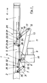
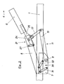
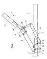
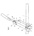
- FIGS. 1 to 5 and 10 to 13 show only the region of a head end
- mattress frame 1 usually from a rectangular frame of two longitudinal beams 2 and two connecting them cross struts 3 exists. It contains several, partly pivotally mounted in him mattress frame parts, of which not shown here are a solid pelvic area, to the foot towards the end connect a pivotable leg part and a pivotable on this footboard. shown are a subsequent to the pelvic part to the head end 4, in the mattress frame 1 pivoted up rear part 5 and a pivotally mounted on this Headboard 6.
- Back part 5 and headboard 6 also consist of frames with longitudinal bars and Crossbars.
- pivot shaft 8 On the mattress frame 1 is in both sides attached to it shields 7 a pivot shaft. 8 stored, preferably by means of a drive device shown only in Figure 1 Engine 9 and gear 10 is rotatable. By means of this pivot shaft 8 are in the following described four-bar pair 11 for pivoting the back part 5, of four-bar pairs or of displacement device pairs for pivoting up and moving the Head part 6 and four-bar pairs or adjusting devices for moving of the back part 5 drivable.
- the first four-bar linkage 11 for pivoting the Rear part 5 arranged.
- Each of these four-bar linkages has four coupling links, the are connected by four joints movable with each other.
- the joints exist preferably from spigot or bolt-shaped shaft / hub connections whose axes perpendicular to the plane of the drawings.
- FIG. 1 to 5 are between the back part 5 and the Head part 6 on both sides two second four-bar linkage 21 is arranged.
- Your virtual base coupling links 22 are located between the rear part 5 arranged joints 16 of the handlebar 17th and further arranged on the back part 5 joints 23.
- the movement initiating Coupling members 24 are formed by extensions of the links 17 to joints 25, sitting on the headboard 6 on both sides bearing shields 26.
- the third coupling links form Handlebar 27, which is arranged between the joints 23 and 26 on the shields Extend joints 28.
- the virtual fourth coupling member 29 finally lie between the joints 25 and 28.
- the coupling members 17 of the first four-bar linkage 11 and the coupling links 24 of the second Viergelenkpases 21 represent arms one-piece, double-armed lever 17/24. So are the two four-bar linkage pairs 11 and 21 are motion-connected.
- the geometric arrangement of the coupling members of the four-bar linkage 11 and 21 and their Pivot points is made so that the high pivoting movement of the head part 6 opposite the back part 5 to a high pivoting angle of the same of about 12 ° pivoting of the back part by no more than 5 °, so not noticeably ahead. Only at one High pivoting angle of the back part of about 30 ° ( Figure 3) reaches the tilt angle of the headboard opposite the back about 20 °. In this case, the head part 6 already shifted substantially in the direction of the head end 4 out.
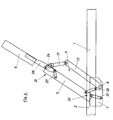
- third four-bar linkage pairs 30 provided. These can be formed by two links 31 and 32, respectively by means of joints 33 and the already introduced joints 14 fixed to the mattress frame. 1 and with joints 35 and 36 at different distances at the lower end of the back part 5 are articulated. Between the joints 14 and 33 here is the dash-dotted lines indicated Base coupling member, while the links 31, 32 and the portion of the back part 5 between the joints 35 and 36 form the other coupling links.
- This displacement of the back part 5 can alternatively also by means of displacement devices be achieved, as disclosed in German Utility Model 299 05 092.0 are referred to. These devices are described below described.
- the pivot shaft 8 is the 8th connected to a gear 38 which in a second, also rotatably mounted in the plate 7
- Gear 39 engages preferably larger numbers of teeth.
- levers 40 are fixed on both sides of the frame of the back part, which are connected via pivot pins 41 with the lower end of the back part 5.
- levers 43 are provided which stored on the one hand in the plate 7, on the other hand with the back part 5 at the lower end are connected via a pivot pin 41.
- handlebar 44 which is offset from the pivot shaft 8 and the Swing levers 13 are articulated.
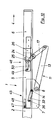
- Displacement device pairs 45 and 46 are used according to Figures 10 to 13, which moved by handlebars or by crank arms, guided at their end in scenes Have drag lever.
- the swiveling up of the back part 5 serves here already It is understood that rocker arm displacement devices according to the figures 10 to 13 with four-joint displacement devices of Figures 1 to 5 or with displacement devices of Figures 6 to 9 can be combined.
- the displacement device pair 45 for moving the back part 5 uses here only the handlebar 32, articulated with their joints 14 and 36 on the plate 7 and the back part 5 are.
- the back part sliders are, for example.
- bolts 47th arranged in the longitudinal direction of the mattress frame 1 parallel scenes 48 stirred are.
- the sliders can also be performed in rails with C-shaped cross-section. Backdrops 48 or rails can also be bent if a certain path of movement of the back part 5 is desired.
- the displacement device pair 46 for moving and pivoting the Headboard 6 here use the previously described extensions 24, which with their terminal joints 25 connected to the head part 6 supporting shields 26 are, as the headboard moving crank arms.
- the shields 26 are also here bolt-like sliders 49 are provided, which are guided in curved scenes 50.
- the scenes 50 are here arcuately down and then led back up and ends in straight, sloping end pieces.
- the scenes 50 can also be different be shaped to achieve other courses of pivoting of the head part.
Landscapes
- Health & Medical Sciences (AREA)
- General Health & Medical Sciences (AREA)
- Nursing (AREA)
- Invalid Beds And Related Equipment (AREA)
Abstract
Description
- Fig. 1 bis 5
- die schematische Seitenansicht einer ersten Ausführungsform der Erfindung durch das dem Kopfende zugewandten Bereich eines Matratzenrahmens mit jeweils zunehmendem Winkel des Anhebens des Rückenteils;
- Fig. 6 und 7
- eine alternative Vorrichtung zum Verschieben des Rückenteils;
- Fig. 8 und 9
- eine weitere Vorrichtung zum Verschieben des Rückenteils;
- Fig. 10 bis 13
- eine zweite Ausführungsform der Erfindung in Darstellung wie in den Fig.1 bis 5.
- 1
- Matratzenrahmen
- 2
- Längsholm
- 3
- Querstrebe
- 4
- Kopfende
- 5
- Rückenteil
- 6
- Kopfteil
- 7
- Schild
- 8
- Schwenkwelle
- 9
- Motor
- 10
- Getriebe
- 11
- Erste Viergelenkpaare
- 12
- Basis-Koppelglied
- 13
- Schwenkhebel
- 14
- Gelenk am Basis-Koppelglied
- 15
- Gelenk am Lenker 17
- 16
- Gelenk am Lenker 17
- 17
- Lenker
- 18
- Lasche für Gelenk 16
- 19 20 21
- Zweite Viergelenkpaare
- 22
- Basis-Koppelglied
- 23
- Gelenk am Rückenteil 5
- 24
- Bewegung einleitendes
Koppelglied - 25
- Gelenk am Schild
- 26
- Das Kopfteil 6 tragendes Schild
- 27
- Lenker
- 28
- Koppelglied
- 29
- Koppelglied
- 30
- Dritte Viergelenkpaare
- 31
- Lenker
- 32
- Lenker
- 33
- Gelenke am Matratzenrahmen
- 34
- Gelenke am Matratzenrahmen
- 35
- Gelenke am Rückenteil 5
- 36
- Gelenke am Rückenteil 5
- 37
- Verlagerungsvorrichtung
Rückenteil - 38
- Zahnrad
- 39
- Zahnrad
- 40
- Stellhebel
- 41
- Schwenkzapfen
- 42
- Verlagerungsvorrichtung
Rückenteil - 43
- Stellhebel
- 44
- Lenker
- 45
- Verlagerungsvorrichtung
Rückenteil - 46
- Verlagerungsvorrichtung
Kopfteil - 47
- Gleitstück
- 48
- Kulisse
- 49
- Gleitstück
- 50
- Gebogene Kulisse
Claims (7)
- Matratzenrahmen ( 1 ) mit einem in ihm verschwenkbar gelagerten und gegen das Kopfende (4) verschiebbaren Rückenteil (5) und einem am Rückenteil verschwenkbar gelagerten und gegen das Kopfende (4) verschiebbaren Kopfteil (6), wobeizumindest das Rückenteil (5) mittels eines Viergelenkpaares (11) hochschwenkbar ist,das Rückenteil (5) mittels einer mit den Viergelenken (11) bewegungsverbundenen Verlagerungsvorrichtungspaares (30, 37, 42, 45) beim Hochschenken in Richtung auf das Kopfende ( 4) des Matratzenrahmens ( 1 ) verschiebbar ist,das Kopfteil (6) mittels eines mit den Viergelenken (11) bewegungsverbundenen Verlagerungsvorrichtungspaares (21, 46) beim Hochschwenken des Rückenteils (5) gegenüber dem Rückenteil vor und zurück schwenkbar und in Richtung auf das Kopfende (4) des Matratzenrahmens ( 1 ) verschiebbar ist.
- Matratzenrahmen (1) nach Anspruch 1, dadurch gekennzeichnet, dass zumindest eines der Verlagerungsvorrichtungspaare (21, 30) aus einem weiteren Viergelenkpaar besteht.
- Matratzenrahmen ( 1 ) nach Anspruch 1, dadurch gekennzeichnet, dass zumindest eines der Verlagerungsvorrichtungspaare (45, 46) durch Lenker (32, 24) gezogene Schlepphebel (5, 26) umfasst, die mittels Gleitstücken (47, 49) in Kulissen (48, 50) geführt sind.
- Matratzenrahmen ( 1 ) nach Anspruch 2, dadurch gekennzeichnet, dass jeweils ein Lenker (17) der das Rückenteil (5) bewegenden Viergelenke (11) eine Verlängerung (24) aufweist, die einen Lenker des das Kopfteil (6) bewegenden Viergelenkpaares (21) bildet.
- Matratzenrahmen ( 1 ) nach Anspruch 2, dadurch gekennzeichnet, dass die Anlenkpunkte (16, 25; 23, 28) der Koppelglieder (24) bzw. der Lenker (27) der als Viergelenke ausgebildeten Verlagerungsvorrichtungspaare (21) derart gewählt sind, dass die Schwenkbögen der am Rückenteil (5) schwenkbar gelagerten und die Bewegung in die Viergelenkpaare (21) einleitenden Koppelglieder (24) und der ebenfalls am Rückenteil schwenkbar gelagerten Lenker (27) einander entgegengesetzt sind.
- Matratzenrahmen (1) nach einem der Ansprüche 2 oder 3, dadurch gekennzeichnet, dass die das Kopfteil (6) vor und zurück verschwenkenden und gegen das Kopfende (4) verschiebenden Verlagerungsvorrichtungspaare (21, 46) derart gestaltet sind, dass das Kopfteil (6) in einem Anfangsbereich der Hochschwenkbewegung des Rückenteils (5) bis etwa 12° Schwenkstellung der Schwenkbewegung desselben nicht oder nicht fühlbar voreilt; in einem Mittelbereich der Hochschwenkbewegung des Rückenteils (5) bis etwa 30° Schwenkstellung der Schwenkbewegung desselben zunehmend um bis zu 30° voreilt und in einem Endbereich der Hochschwenkbewegung des Rückenteils (5) bis etwa 60° Schwenkstellung die erreichte Voreilung bis mindestens nahe der fluchtenden Stellung mit dem Rückenteil (5) abbaut.
- Matratzenrahmen ( 1 ) nach Anspruch 6, dadurch gekennzeichnet, dass die Verlagerungsvorrichtungspaare (21, 46) für das Kopfteil (6) in einer maximalen Hochschwenkstellung des Rückenteils (5) das Kopfteil (6) in eine Rückhangstellung gegenüber dem Rückenteil (5) führen.
Applications Claiming Priority (4)
| Application Number | Priority Date | Filing Date | Title |
|---|---|---|---|
| DE10339554 | 2003-08-26 | ||
| DE10339554 | 2003-08-26 | ||
| DE102004006423 | 2004-02-09 | ||
| DE102004006423 | 2004-02-09 |
Publications (2)
| Publication Number | Publication Date |
|---|---|
| EP1510152A1 true EP1510152A1 (de) | 2005-03-02 |
| EP1510152B1 EP1510152B1 (de) | 2010-03-17 |
Family
ID=33453896
Family Applications (1)
| Application Number | Title | Priority Date | Filing Date |
|---|---|---|---|
| EP20040020033 Expired - Lifetime EP1510152B1 (de) | 2003-08-26 | 2004-08-24 | Matratzenrahmen mit daran schwenkbarem Rückenteil und Kopfteil |
Country Status (2)
| Country | Link |
|---|---|
| EP (1) | EP1510152B1 (de) |
| DE (2) | DE202004013295U1 (de) |
Cited By (1)
| Publication number | Priority date | Publication date | Assignee | Title |
|---|---|---|---|---|
| CN108158280A (zh) * | 2018-01-10 | 2018-06-15 | 绍兴古洛奇寝具股份有限公司 | 一种能五段式调整躺卧角度的人体工学床垫 |
Families Citing this family (1)
| Publication number | Priority date | Publication date | Assignee | Title |
|---|---|---|---|---|
| DE102014102216A1 (de) * | 2014-02-20 | 2015-08-20 | Dewertokin Gmbh | Beschlag für ein Lattenrost mit einem Schwenkelement |
Citations (7)
| Publication number | Priority date | Publication date | Assignee | Title |
|---|---|---|---|---|
| DE8716122U1 (de) | 1987-12-05 | 1988-01-21 | Stanzwerk Wetter Sichelschmidt & Co, 5802 Wetter | Vorrichtung zum Verstellen eines an einem Matratzenrahmen angelenkten Kopfteiles |
| FR2700109A1 (fr) * | 1993-01-07 | 1994-07-08 | Renault Creations Andre | Perfectionnement aux sommiers à dosseret relevable pour literie. |
| EP0761137A1 (de) * | 1995-08-25 | 1997-03-12 | Compagnie Continentale Simmons | Lattenrost mit einem aufstellbaren und ausziehbaren Rückenabschnitt |
| DE29905092U1 (de) | 1999-03-19 | 1999-06-10 | Schwenk, Hans Ulrich, Dipl.-Ing., 72766 Reutlingen | Verschwenklagerung |
| DE20006120U1 (de) | 2000-04-03 | 2000-05-25 | Franke GmbH & Co KG, 72336 Balingen | Lattenrost |
| DE20017758U1 (de) * | 2000-10-17 | 2000-12-14 | Stanzwerk Wetter Sichelschmidt GmbH & Co. KG, 58300 Wetter | Vorrichtung zum Verstellen des Rückenteils und mit Kopfteil eines Liegemöbels |
| FR2798270A1 (fr) * | 1999-09-10 | 2001-03-16 | Creations Andre Renault | Sommier a dossier articule et dispositif de liaison d'elements du dossier |
-
2004
- 2004-08-24 DE DE202004013295U patent/DE202004013295U1/de not_active Expired - Lifetime
- 2004-08-24 DE DE200450010898 patent/DE502004010898D1/de not_active Expired - Lifetime
- 2004-08-24 EP EP20040020033 patent/EP1510152B1/de not_active Expired - Lifetime
Patent Citations (7)
| Publication number | Priority date | Publication date | Assignee | Title |
|---|---|---|---|---|
| DE8716122U1 (de) | 1987-12-05 | 1988-01-21 | Stanzwerk Wetter Sichelschmidt & Co, 5802 Wetter | Vorrichtung zum Verstellen eines an einem Matratzenrahmen angelenkten Kopfteiles |
| FR2700109A1 (fr) * | 1993-01-07 | 1994-07-08 | Renault Creations Andre | Perfectionnement aux sommiers à dosseret relevable pour literie. |
| EP0761137A1 (de) * | 1995-08-25 | 1997-03-12 | Compagnie Continentale Simmons | Lattenrost mit einem aufstellbaren und ausziehbaren Rückenabschnitt |
| DE29905092U1 (de) | 1999-03-19 | 1999-06-10 | Schwenk, Hans Ulrich, Dipl.-Ing., 72766 Reutlingen | Verschwenklagerung |
| FR2798270A1 (fr) * | 1999-09-10 | 2001-03-16 | Creations Andre Renault | Sommier a dossier articule et dispositif de liaison d'elements du dossier |
| DE20006120U1 (de) | 2000-04-03 | 2000-05-25 | Franke GmbH & Co KG, 72336 Balingen | Lattenrost |
| DE20017758U1 (de) * | 2000-10-17 | 2000-12-14 | Stanzwerk Wetter Sichelschmidt GmbH & Co. KG, 58300 Wetter | Vorrichtung zum Verstellen des Rückenteils und mit Kopfteil eines Liegemöbels |
Cited By (2)
| Publication number | Priority date | Publication date | Assignee | Title |
|---|---|---|---|---|
| CN108158280A (zh) * | 2018-01-10 | 2018-06-15 | 绍兴古洛奇寝具股份有限公司 | 一种能五段式调整躺卧角度的人体工学床垫 |
| CN108158280B (zh) * | 2018-01-10 | 2023-09-12 | 绍兴古洛奇寝具股份有限公司 | 一种能五段式调整躺卧角度的人体工学床垫 |
Also Published As
| Publication number | Publication date |
|---|---|
| EP1510152B1 (de) | 2010-03-17 |
| DE202004013295U1 (de) | 2004-11-11 |
| DE502004010898D1 (de) | 2010-04-29 |
Similar Documents
| Publication | Publication Date | Title |
|---|---|---|
| EP0885576B1 (de) | Sitzmöbel, insbesondere Bürodrehstuhl | |
| DE2141022C3 (de) | Zahnärztlicher Patientenstuhl mit neigbarer Rückenlehne und verstellbarem Sitz | |
| DE102006038736B4 (de) | Sessel | |
| DE1404651C3 (de) | Verstellsessel mit ausschwenkbarer Beinstütze | |
| DE102005051236B4 (de) | Sessel | |
| EP3387957A1 (de) | Synchronmechanik für einen bürostuhl | |
| EP1013198B1 (de) | Sitz für einen Schiebewagen, Stuhl oder dergleichen | |
| DE202004016889U1 (de) | Sitzmöbel | |
| DE2525596C3 (de) | ||
| DE102006023981A1 (de) | Stuhl | |
| EP1510152A1 (de) | Matratzenrahmen mit daran schwenkbarem Rückenteil und Kopfteil | |
| BE1019628A3 (de) | Sitzmöbel mit aufstehhilfe. | |
| DE3347255A1 (de) | Zahnaerztlicher patientenstuhl mit kopfstuetze | |
| DE69714910T2 (de) | Verstellvorrichtung | |
| DE102013208178B4 (de) | Stuhl mit Sitzmechanik | |
| DE4310443C2 (de) | Kranken- oder Pflegebett | |
| DE1294616B (de) | Hebelverstellgetriebe fuer Verstellsessel mit ausschwenkbarer Beinstuetze zum Einstellen in eine Sitzstellung, eine Ruecklehnstellung und eine Ruhestellung | |
| DE9408845U1 (de) | Hubbett | |
| DE701339C (de) | Einstellvorrichtung fuer zwei sich kreuzende Gestellteile eines verstellbaren Sitzliegemoebels | |
| DE102005011969B3 (de) | Auflageteil für Liegemöbel | |
| WO2004039653A1 (de) | Kinderwagen mit elektromotorisch verschwenkbarer rückenlehne | |
| DE102016116893A1 (de) | Sitzmöbel mit ausschwenkbarer Fußstütze | |
| DE202021002186U1 (de) | Matratzenunterfederung mit motorischer Kniewinkelverstellung | |
| DE202015006541U1 (de) | Polstermöbel | |
| DE202012003534U1 (de) | Sitz-/Liegemöbel |
Legal Events
| Date | Code | Title | Description |
|---|---|---|---|
| PUAI | Public reference made under article 153(3) epc to a published international application that has entered the european phase |
Free format text: ORIGINAL CODE: 0009012 |
|
| AK | Designated contracting states |
Kind code of ref document: A1 Designated state(s): AT BE BG CH CY CZ DE DK EE ES FI FR GB GR HU IE IT LI LU MC NL PL PT RO SE SI SK TR |
|
| AX | Request for extension of the european patent |
Extension state: AL HR LT LV MK |
|
| 17P | Request for examination filed |
Effective date: 20050829 |
|
| AKX | Designation fees paid |
Designated state(s): BE DE ES FR IT |
|
| RAP1 | Party data changed (applicant data changed or rights of an application transferred) |
Owner name: HETTICH FRANKE GMBH & CO. KG |
|
| RIN1 | Information on inventor provided before grant (corrected) |
Inventor name: SCHWENK, HANS ULRICH |
|
| GRAP | Despatch of communication of intention to grant a patent |
Free format text: ORIGINAL CODE: EPIDOSNIGR1 |
|
| GRAS | Grant fee paid |
Free format text: ORIGINAL CODE: EPIDOSNIGR3 |
|
| GRAA | (expected) grant |
Free format text: ORIGINAL CODE: 0009210 |
|
| AK | Designated contracting states |
Kind code of ref document: B1 Designated state(s): BE DE ES FR IT |
|
| REF | Corresponds to: |
Ref document number: 502004010898 Country of ref document: DE Date of ref document: 20100429 Kind code of ref document: P |
|
| PG25 | Lapsed in a contracting state [announced via postgrant information from national office to epo] |
Ref country code: ES Free format text: LAPSE BECAUSE OF FAILURE TO SUBMIT A TRANSLATION OF THE DESCRIPTION OR TO PAY THE FEE WITHIN THE PRESCRIBED TIME-LIMIT Effective date: 20100628 |
|
| PLBE | No opposition filed within time limit |
Free format text: ORIGINAL CODE: 0009261 |
|
| STAA | Information on the status of an ep patent application or granted ep patent |
Free format text: STATUS: NO OPPOSITION FILED WITHIN TIME LIMIT |
|
| 26N | No opposition filed |
Effective date: 20101220 |
|
| BERE | Be: lapsed |
Owner name: HETTICH FRANKE G.M.B.H. & CO. KG Effective date: 20100831 |
|
| PG25 | Lapsed in a contracting state [announced via postgrant information from national office to epo] |
Ref country code: IT Free format text: LAPSE BECAUSE OF FAILURE TO SUBMIT A TRANSLATION OF THE DESCRIPTION OR TO PAY THE FEE WITHIN THE PRESCRIBED TIME-LIMIT Effective date: 20100317 |
|
| REG | Reference to a national code |
Ref country code: FR Ref legal event code: ST Effective date: 20110502 |
|
| PG25 | Lapsed in a contracting state [announced via postgrant information from national office to epo] |
Ref country code: FR Free format text: LAPSE BECAUSE OF NON-PAYMENT OF DUE FEES Effective date: 20100831 Ref country code: BE Free format text: LAPSE BECAUSE OF NON-PAYMENT OF DUE FEES Effective date: 20100831 |
|
| REG | Reference to a national code |
Ref country code: DE Ref legal event code: R084 Ref document number: 502004010898 Country of ref document: DE |
|
| PGFP | Annual fee paid to national office [announced via postgrant information from national office to epo] |
Ref country code: DE Payment date: 20200824 Year of fee payment: 17 |
|
| REG | Reference to a national code |
Ref country code: DE Ref legal event code: R119 Ref document number: 502004010898 Country of ref document: DE |
|
| PG25 | Lapsed in a contracting state [announced via postgrant information from national office to epo] |
Ref country code: DE Free format text: LAPSE BECAUSE OF NON-PAYMENT OF DUE FEES Effective date: 20220301 |