EP0885576B1 - Sitzmöbel, insbesondere Bürodrehstuhl - Google Patents
Sitzmöbel, insbesondere Bürodrehstuhl Download PDFInfo
- Publication number
- EP0885576B1 EP0885576B1 EP98110537A EP98110537A EP0885576B1 EP 0885576 B1 EP0885576 B1 EP 0885576B1 EP 98110537 A EP98110537 A EP 98110537A EP 98110537 A EP98110537 A EP 98110537A EP 0885576 B1 EP0885576 B1 EP 0885576B1
- Authority
- EP
- European Patent Office
- Prior art keywords
- lever
- seat plate
- hinge point
- seat
- hinge
- Prior art date
- Legal status (The legal status is an assumption and is not a legal conclusion. Google has not performed a legal analysis and makes no representation as to the accuracy of the status listed.)
- Expired - Lifetime
Links
Images

Classifications
-
- A—HUMAN NECESSITIES
- A47—FURNITURE; DOMESTIC ARTICLES OR APPLIANCES; COFFEE MILLS; SPICE MILLS; SUCTION CLEANERS IN GENERAL
- A47C—CHAIRS; SOFAS; BEDS
- A47C1/00—Chairs adapted for special purposes
- A47C1/02—Reclining or easy chairs
- A47C1/031—Reclining or easy chairs having coupled concurrently adjustable supporting parts
- A47C1/032—Reclining or easy chairs having coupled concurrently adjustable supporting parts the parts being movably-coupled seat and back-rest
- A47C1/03205—Reclining or easy chairs having coupled concurrently adjustable supporting parts the parts being movably-coupled seat and back-rest having adjustable and lockable inclination
-
- A—HUMAN NECESSITIES
- A47—FURNITURE; DOMESTIC ARTICLES OR APPLIANCES; COFFEE MILLS; SPICE MILLS; SUCTION CLEANERS IN GENERAL
- A47C—CHAIRS; SOFAS; BEDS
- A47C1/00—Chairs adapted for special purposes
- A47C1/02—Reclining or easy chairs
- A47C1/031—Reclining or easy chairs having coupled concurrently adjustable supporting parts
- A47C1/032—Reclining or easy chairs having coupled concurrently adjustable supporting parts the parts being movably-coupled seat and back-rest
- A47C1/03255—Reclining or easy chairs having coupled concurrently adjustable supporting parts the parts being movably-coupled seat and back-rest with a central column, e.g. rocking office chairs
Definitions
- the present invention relates to seating, in particular Office swivel chair, with one foot, one of which is a central column runs upwards, the center column being variable in length and / or can be sprung with an am upper end of the center column fixed seat support, with a seat plate that is close to its front edge a horizontal axis pivotable with the seat support connected and by a spring arrangement with a is biased above, and with a Backrest on at least one upward Lever is attached, which is under the seat plate in a first articulation point articulated with the seat support and articulated at a distance from it at a second articulation point is connected to the underside of the seat plate, wherein both articulation points parallel to the pivoting axis of the seat plate Have pivot axes.
- Seating of the type mentioned is from the U.S. Patent 4,709,962 known. With such seating serves to support the backrest on the seat support and the lever hinged to the seat plate, a coupled To produce movement of the seat plate and backrest. Specifically, the coupling is that the backrest also when the seat plate is pivoted pivoted, but at a different angle than that Seat plate.
- the ratio of the swivel angles to each other is well known in the relevant market today Seating to a predetermined value in the area between about 1: 1.3 and 1: 2.5.
- DE 44 39 290 A1 describes a synchronous adjustment device known for office chairs, seating and the like, consisting of a seat part, a back part with a attached to or integrated into a back support Backrest and a fixed support frame, on which the seat part is articulated, the back support connected to the seat part and the support frame is and the seat part with an increase in the back inclination performs a pivoting movement.
- the back support immediately both with the seat part and with the support frame is pivotally connected.
- this adjustment device is used in at least one of the Swivel connections a link guide for the axis of rotation to overlay a displacement movement with the rotational movement around the pivot axis is provided.
- a link guide for the axis of rotation to overlay a displacement movement with the rotational movement around the pivot axis is provided.
- the disadvantage of this Synchronizing device viewed that the course the synchronous movements of the seat part and the back part is determined by the shape of the backdrop and no longer influenced by the user of the seating can be.
- Seating described a synchronous adjustment provided in such a way that when the Backrest back the seat plate to your rear End is raised and that vice versa when pivoting the backrest forward the seat plate in the back is lowered. This type of synchronous adjustment is no longer regarded as ergonomically favorable.
- This object is achieved according to the invention by a seating of the type mentioned, characterized in that is that the length of the lever between the first articulation point and the second articulation point by moving the first articulation point and / or the second Articulation point in the direction of the lever is changeable.
- the backrest can either rigidly attached to the upper, free end of the lever or about an axis parallel to the seat plate pivot axis hinged to the upper, free end of the lever his.
- the illustrated embodiment includes a seat 1, here an office swivel chair, one Foot 2, a seat support 3 connected to foot 2, a pivotable on the seat support 3 seat plate 4 and a backrest 5.
- the foot 2 comprises several, generally five arms 20, which each carry a roller 21 at their outer end. To the foot 2 also includes a center column 22, the extends centrally upwards and the length can be changed and / or can be sprung.
- the foot 2 is total of known construction and therefore only in the drawing shown in dotted lines.
- the seat support 3 is at one end 32 with the upper end of the center column 22 firmly connected, a Lift the seat support 3 upwards from the center column 22 is excluded, but rotation of the seat support 3 around the central column 22 remains possible.
- the seat support 3 points obliquely in its course above, with its outer end 34 connecting to the seat plate 4 by means of a pivot axis 43 which is in the horizontal direction parallel to the front edge of the seat plate 4 runs, produces.
- the pivot axis 43 is preferred realized by a corresponding joint; alternative can also pivot axis 43 by using a flexible material can be realized, the corresponding one Pivotal movement of the seat plate 4 relative to his seat support 3 allowed.
- a spring element is provided, that the seat plate 4 with one pointing upwards Force preloaded. When using the flexible material This can also be done with sufficient elasticity even apply the spring force.
- the backrest 5 extends upwards but no direct connection between the seat plate 4 and the backrest 5.
- the backrest 5 is rather via a lever 6 with the rest of the Seating 1 connected.
- the lever 6 is in two articulation points 63 and 64 on the one hand with the seat support and on the other other connected to the seat plate 4.
- the Articulation point 63 as in a guide 36 in the seat support 3 displaceable and lockable articulation element.
- the pivot point 64 is stationary on the underside 42 of the seat plate 4 attached, but one Displacement of the lever 6 in its longitudinal direction by the pivot point 64 remains possible.
- the lever 6 At the pivot point 63 is the front one, left in the drawing End 61 of the lever 6 against movements in the longitudinal direction the lever 6 set. To the right of the second articulation point 64, the lever 6 initially runs below the seat plate 4 backwards, i.e. to the right in the drawing, and then turns upwards. At its upper end 62 the lever 6 is connected to the backrest 5, wherein the backrest in the present exemplary embodiment 5 oscillating about an axis 56 with the lever end 62 connected is.
- the top 41 of the seat plate 4 and the front 51 of the backrest 5 are padded in the usual way as well as with a coating, e.g. made of fabric or Leather, provided.
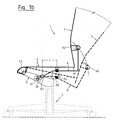
- Figure 1a is a position in solid lines of the seating furniture 1 drawn with the seat plate 4 raised, in which a user of the seat 1 an erect Attitude.
- a user of the seat 1 By shifting his weight can the user of the seating 1 his posture change on the seating 1 and the seat plate 4 against the force of the above-mentioned spring element in a move diagonally backwards and downwards, which is drawn in dashed lines.
- the available swivel range of the seat plate 4 is in the embodiment shown Figure 1a and also in the other figures of the drawing each 12 °.
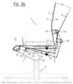
- Figures 2a to 2c show an embodiment of the seating 1, in contrast to the previous example 1a and 1b now the second articulation point 64 is changeable in its position during the first articulation point 63 is stationary on the seat support 3.
- this exemplary embodiment also comprises the seat 1, which is again an office swivel chair, one conventional foot 2, at the upper end of the seat support 3 is attached with its lower end 32.
- the Seat plate 4 is here again about the pivot axis 43 articulated or flexible with the same effect with the seat support 3 connected at its free end 34. Behind the Seat plate 4 extends backrest 5 again up.
- connection of the backrest 5 with the rest of the part of the furniture 1 again takes over a lever 6, the underneath the seat plate 4 on the underside 42 thereof runs and behind the seat plate 4 upwards is bent and there at its free end 62 the Backrest 5 carries. Again, there is a commuting Connection provided with an axis 56.
- a guide 46 is provided, along which the as Articulation element formed second articulation point 64 slidably and can be set in desired positions.
- the lever 6 runs through the second pivot point 64 through, with a relative movement between lever 6 and pivot point 64 in the longitudinal direction of the lever remains possible.
- the front end 61 of the lever 6 is in the first pivot point 61 around a horizontal axis parallel to Swivel axis 43 extends, movably mounted, otherwise but secured against movements in other directions.
- the connection also results the backrest 5 via the lever 6 with the seat plate 4 and the seat support 3 a coupled movement of Seat plate 4 and backrest 5 when the seat plate 4 is lowered by load from a user.
- Essential for the swivel angle ratio between the seat plate 4 and backrest 5 is again the length L of the lever part 60 between the two articulation points 63 and 64.
- the second articulation point 64 or the articulation element forming it in its leadership 46 approximately to the back side Stop moved, making the length L approximately receives its maximum possible value.
- this location of the second pivot point 64 results at a pivot angle the seat plate 4 of 12 ° for the backrest 5 a swivel angle of 16 °.
- the swiveled Position of seat plate 4 and backrest 5 also in the figure 2a and in the other figures in dashed lines Lines shown.
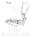
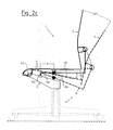
- Figure 2c finally shows the seating 1 from Figure 2a and 2b now with a third position of the second articulation point 64, in which this as far as possible within its guide 46 is moved forward.
- the length L hereby almost reaches its minimum possible value, which leads to the fact that when the seat plate is pivoted 4 by 12 ° the backrest 5 performs a pivoting through 22 °.
- the guide 46 on the underside 42 of the seat plate 4 can be executed relatively easily with a large length there is a correspondingly large range of variation for the length L and therefore correspondingly larger Range of variation for the swivel angle ratio between Seat plate 4 and backrest 5.
- Even larger ranges of variation become possible if the range of variation the length L is additionally increased, either by Extension of guides 36 and / or 46 or by use of two movable articulation points 63 and 64.
Landscapes
- Health & Medical Sciences (AREA)
- Dentistry (AREA)
- General Health & Medical Sciences (AREA)
- Chairs For Special Purposes, Such As Reclining Chairs (AREA)
- Chairs Characterized By Structure (AREA)
- Special Chairs (AREA)
Description
- Figur 1a
- ein Sitzmöbel in einer ersten Ausführung mit einem ersten Schwenkwinkelverhältnis zwischen Sitzplatte und Rückenlehne, in zwei unterschiedlichen Verschwenkungszuständen, in schematischer Seitenansicht,
- Figur 1b
- das Sitzmöbel aus Figur 1a, mit einem geänderten Schwenkwinkelverhältnis, in gleicher Darstellungsweise wie Figur 1a,
- Figur 2a
- das Sitzmöbel in einer zweiten Ausführung, mit einem ersten Schwenkwinkelverhältnis zwischen Sitzplatte und Rückenlehne, ebenfalls in schematischer Seitenansicht,
- Figur 2b
- das Sitzmöbel aus Figur 2a, nun mit einem zweiten Schwenkwinkelverhältnis, und
- Figur 2c
- das Sitzmöbel aus Figur 2a, nun mit einem dritten Schwenkwinkelverhältnis.
Claims (10)
- Sitzmöbel (1), insbesondere Bürodrehstuhl, mit einem Fuß (2), von dem eine Mittelsäule (22) nach oben verläuft, wobei die Mittelsäule (22) längenvariabel und/oder gefedert sein kann, mit einem am oberen Ende der Mittelsäule (22) fest angebrachten Sitzträger (3), mit einer Sitzplatte (4), die nahe ihrer Vorderkante um eine horizontale Achse (43) verschwenkbar mit dem Sitzträger (3) verbunden und durch eine Federanordnung mit einer nach oben weisenden Kraft vorbelastet ist, und mit einer Rückenlehne (5), die an mindestens einem nach oben verlaufenden Hebel (6) angebracht ist, der unter der Sitzplatte (4) in einem ersten Anlenkpunkt (63) gelenkig mit dem Sitzträger (3) und im Abstand davon in einem zweiten Anlenkpunkt (64) gelenkig mit der Unterseite (42) der Sitzplatte (4) verbunden ist, wobei beide Anlenkpunkte (63, 64) zur Sitzplattenschwenkachse (43) parallele Schwenkachsen aufweisen,
dadurch gekennzeichnet, daß die Länge (L) des Hebels (6) zwischen dem ersten Anlenkpunkt (63) und dem zweiten Anlenkpunkt (64) durch Verschieben des ersten Anlenkpunktes (63) und/oder des zweiten Anlenkpunktes (64) in Richtung des Hebels (6) veränderbar ist. - Sitzmöbel nach Anspruch 1, dadurch gekennzeichnet, daß der erste Anlenkpunkt (63) als in einer Führung (36) im Sitzträger (3) stufenlos oder in mehreren Stufen verschiebbares und arretierbares erstes Anlenkelement ausgeführt ist.
- Sitzmöbel nach Anspruch 2, dadurch gekennzeichnet, daß der zweite Anlenkpunkt (64) als ortsfest an der Unterseite (42) der Sitzplatte (4) angebrachtes Schwenklager ausgeführt ist.
- Sitzmöbel nach Anspruch 2 oder 3, dadurch gekennzeichnet, daß der Hebel (6) in dem ersten Anlenkpunkt (63) relativ zu diesem in seiner Längsrichtung verschieblich geführt ist.
- Sitzmöbel nach Anspruch 4, dadurch gekennzeichnet, daß der Hebel (6) in dem ersten Anlenkpunkt (63) gegen Verschiebung in seiner Längsrichtung lösbar arretierbar ist und daß in dem zweiten Anlenkpunkt (64) der Hebel (6) in seiner Längsrichtung verschieblich geführt ist.
- Sitzmöbel nach Anspruch 1, dadurch gekennzeichnet, daß der zweite Anlenkpunkt (64) als in einer Führung (46) an der Unterseite (42) der Sitzplatte (4) stufenlos oder in mehreren Stufen verschiebbares und arretierbares zweites Anlenkelement ausgeführt ist.
- Sitzmöbel nach Anspruch 6, dadurch gekennzeichnet, daß der erste Anlenkpunkt (63) als ortsfest am Sitzträger (3) angebrachtes Schwenklager ausgeführt ist.
- Sitzmöbel nach Anspruch 6 oder 7, dadurch gekennzeichnet, daß der Hebel (6) in dem zweiten Anlenkpunkt (64) relativ zu diesem in seiner Längsrichtung verschieblich geführt ist und daß in dem ersten Anlenkpunkt (63) das Hebelende (61) axial unverschieblich gehaltert ist.
- Sitzmöbel nach einem der Ansprüche 1 bis 8, dadurch gekennzeichnet, daß die Rückenlehne (5) starr am oberen, freien Ende (62) des Hebels (6) angebracht ist.
- Sitzmöbel nach einem der Ansprüche 1 bis 8, dadurch gekennzeichnet, daß die Rückenlehne (5) um eine zur Sitzplattenschwenkachse (43) parallele Achse (56) pendelnd am oberen, freien Ende (62) des Hebels (6) angelenkt ist.
Applications Claiming Priority (2)
| Application Number | Priority Date | Filing Date | Title |
|---|---|---|---|
| DE19726160A DE19726160A1 (de) | 1997-06-20 | 1997-06-20 | Sitzmöbel, insbesondere Bürodrehstuhl |
| DE19726160 | 1997-06-20 |
Publications (3)
| Publication Number | Publication Date |
|---|---|
| EP0885576A2 EP0885576A2 (de) | 1998-12-23 |
| EP0885576A3 EP0885576A3 (de) | 2000-05-10 |
| EP0885576B1 true EP0885576B1 (de) | 2002-10-09 |
Family
ID=7833092
Family Applications (1)
| Application Number | Title | Priority Date | Filing Date |
|---|---|---|---|
| EP98110537A Expired - Lifetime EP0885576B1 (de) | 1997-06-20 | 1998-06-09 | Sitzmöbel, insbesondere Bürodrehstuhl |
Country Status (5)
| Country | Link |
|---|---|
| US (1) | US6000755A (de) |
| EP (1) | EP0885576B1 (de) |
| CA (1) | CA2240248C (de) |
| DE (2) | DE19726160A1 (de) |
| ES (1) | ES2185085T3 (de) |
Families Citing this family (39)
| Publication number | Priority date | Publication date | Assignee | Title |
|---|---|---|---|---|
| EP1265513B1 (de) * | 2000-03-24 | 2005-01-19 | Giroflex-Entwicklungs-AG | Sitz- und rückenlehnenanordnung bei sitzmöbeln, insbesondere bürostühlen |
| DE10026531C2 (de) * | 2000-05-27 | 2002-06-13 | Roeder Peter | Stuhl |
| IT1320421B1 (it) * | 2000-06-09 | 2003-11-26 | Pro Cord Srl | Sedia con sedile e schienale oscillanti in modo sincronizzato. |
| US6820934B2 (en) * | 2000-11-09 | 2004-11-23 | Michigan Tube Swagers & Fabricators, Inc. | Chair having flexible back support |
| US6471293B2 (en) | 2000-11-09 | 2002-10-29 | Michigan Tube Swagers & Fabricators, Inc. | Stackable chair with flexible back support |
| DE10122948C1 (de) * | 2001-05-11 | 2003-03-13 | Armin Sander | Stuhl, insbesondere Bürostuhl |
| DE10122946C1 (de) * | 2001-05-11 | 2003-01-30 | Armin Sander | Stuhl, insbesondere Bürostuhl |
| DE10122945A1 (de) * | 2001-05-11 | 2002-12-12 | Armin Sander | Stuhl, insbesondere Bürostuhl |
| US6805412B2 (en) * | 2001-08-30 | 2004-10-19 | Burgess Furniture Ltd. | Stackable chair with flexible back |
| US20030132653A1 (en) * | 2001-10-18 | 2003-07-17 | Doug Thole | Tension control mechanism for a chair |
| WO2004089162A2 (en) * | 2003-04-02 | 2004-10-21 | Wells Harold G | Articulated seating mechanism |
| DE102005020237B3 (de) * | 2005-04-28 | 2006-08-17 | Bock 1 Gmbh & Co. Kg | Synchronmechanik |
| DE102005020247B3 (de) * | 2005-04-28 | 2006-11-30 | Bock 1 Gmbh & Co. Kg | Sitzmöbel, insbesondere Bürostuhl |
| EP2010025A4 (de) * | 2006-04-24 | 2010-11-17 | Humanscale Corp | Stuhl mit sich automatisch einstellbarem widerstand gegen kippen |
| WO2008041868A2 (en) * | 2006-10-04 | 2008-04-10 | Formway Furniture Limited | A chair |
| CH700928B1 (de) * | 2007-10-12 | 2010-11-15 | Sitag Ag | Personensitz mit einer Wippfeder. |
| SE533354C2 (sv) * | 2009-01-29 | 2010-08-31 | Officeline Ab | Kontorsstol |
| DE102011001811A1 (de) * | 2011-04-05 | 2012-10-11 | Wilkhahn Wilkening + Hahne Gmbh + Co. Kg | Stuhl |
| US9073453B2 (en) | 2011-10-07 | 2015-07-07 | Bombardier Inc. | Aircraft seat |
| US9714095B2 (en) | 2011-10-07 | 2017-07-25 | Bombardier Inc. | Aircraft seat |
| US9714862B2 (en) | 2011-10-07 | 2017-07-25 | Bombardier Inc. | Aircraft seat |
| US9592914B2 (en) | 2011-10-07 | 2017-03-14 | Bombardier Inc. | Aircraft seat |
| US9504326B1 (en) | 2012-04-10 | 2016-11-29 | Humanscale Corporation | Reclining chair |
| DE102012212121A1 (de) * | 2012-07-11 | 2014-01-16 | Eb-Invent Gmbh | Sitzvorrichtung |
| USD697726S1 (en) * | 2012-09-20 | 2014-01-21 | Steelcase Inc. | Chair |
| EP3089910B1 (de) | 2013-12-30 | 2022-02-02 | Bombardier Inc. | Flugzeugsitz |
| EP2896325B1 (de) * | 2014-01-20 | 2018-02-28 | L&P Property Management Company | Kippvorrichtung für ein Sitzmöbel und Sitzmöbel damit |
| CN106455821A (zh) | 2014-04-17 | 2017-02-22 | Hni技术公司 | 椅子和椅子控制组件、系统和方法 |
| US10583926B2 (en) | 2014-09-25 | 2020-03-10 | Bombardier Inc. | Aircraft seat |
| GB2530554A (en) | 2014-09-26 | 2016-03-30 | Bombardier Inc | Aircraft seat |
| GB2530556A (en) | 2014-09-26 | 2016-03-30 | Bombardier Inc | Aircraft seat |
| US11259637B2 (en) | 2015-04-13 | 2022-03-01 | Steelcase Inc. | Seating arrangement |
| US10021984B2 (en) | 2015-04-13 | 2018-07-17 | Steelcase Inc. | Seating arrangement |
| US10194750B2 (en) | 2015-04-13 | 2019-02-05 | Steelcase Inc. | Seating arrangement |
| US10966527B2 (en) | 2017-06-09 | 2021-04-06 | Steelcase Inc. | Seating arrangement and method of construction |
| US10383448B1 (en) | 2018-03-28 | 2019-08-20 | Haworth, Inc. | Forward tilt assembly for chair seat |
| ES3035683T3 (en) | 2019-02-21 | 2025-09-08 | Steelcase Inc | Body support member |
| US11357329B2 (en) | 2019-12-13 | 2022-06-14 | Steelcase Inc. | Body support assembly and methods for the use and assembly thereof |
| US20250344860A1 (en) * | 2024-05-08 | 2025-11-13 | Christopher A. Tramutola | Outdoor Seating Techniques |
Family Cites Families (9)
| Publication number | Priority date | Publication date | Assignee | Title |
|---|---|---|---|---|
| DE2335586A1 (de) * | 1973-01-29 | 1975-01-30 | Fritz Kerstholt | Sitz- und/oder liegemoebel mit bewegbarem rueckenteil |
| DE3537203A1 (de) * | 1984-10-24 | 1986-04-24 | Klöber GmbH & Co, 7770 Überlingen | Arbeitsstuhl mit neigungsmechanik von sitzschale und rueckenlehne |
| DE3622272A1 (de) * | 1986-07-03 | 1988-01-21 | Porsche Ag | Stuhl, insbesondere buerostuhl |
| DE3741472A1 (de) * | 1987-12-08 | 1989-06-22 | Simon Desanta | Stuhl |
| DE3916474A1 (de) * | 1989-05-20 | 1990-11-22 | Roeder Soehne Sitzmoebelfab | Stuhl, insbesondere arbeits- oder buerostuhl |
| IL103477A0 (en) * | 1992-10-20 | 1993-03-15 | Paltechnica Nitzanim | Office and like chairs |
| DE4312113C1 (de) * | 1993-04-14 | 1994-10-27 | Mauser Waldeck Ag | Sitzmöbel |
| DE4439290A1 (de) * | 1994-11-07 | 1996-05-09 | Sdm Hansen Ag | Synchronverstelleinrichtung |
| GB9500022D0 (en) * | 1995-01-04 | 1995-03-01 | Unwalla Jamshed | Integrated seat and back and mechanism for chairs |
-
1997
- 1997-06-20 DE DE19726160A patent/DE19726160A1/de not_active Withdrawn
-
1998
- 1998-06-09 EP EP98110537A patent/EP0885576B1/de not_active Expired - Lifetime
- 1998-06-09 ES ES98110537T patent/ES2185085T3/es not_active Expired - Lifetime
- 1998-06-09 DE DE59805870T patent/DE59805870D1/de not_active Expired - Lifetime
- 1998-06-10 CA CA002240248A patent/CA2240248C/en not_active Expired - Fee Related
- 1998-06-19 US US09/100,909 patent/US6000755A/en not_active Expired - Lifetime
Also Published As
| Publication number | Publication date |
|---|---|
| EP0885576A3 (de) | 2000-05-10 |
| CA2240248A1 (en) | 1998-12-20 |
| EP0885576A2 (de) | 1998-12-23 |
| DE59805870D1 (de) | 2002-11-14 |
| ES2185085T3 (es) | 2003-04-16 |
| CA2240248C (en) | 2007-05-01 |
| US6000755A (en) | 1999-12-14 |
| DE19726160A1 (de) | 1998-12-24 |
Similar Documents
| Publication | Publication Date | Title |
|---|---|---|
| EP0885576B1 (de) | Sitzmöbel, insbesondere Bürodrehstuhl | |
| DE19930922B4 (de) | Stuhl | |
| EP1946676B1 (de) | Stuhl | |
| DE3929436C2 (de) | Fahrzeugsitz | |
| DE3879714T2 (de) | Ergonomischer stuhl mit einem verstellbaren sitz. | |
| DE69110472T2 (de) | Arbeitsstuhl. | |
| EP0394307B1 (de) | Stuhl, insbesondere arbeits- oder bürostuhl | |
| EP3409144B1 (de) | Stuhl, insbesondere konferenz- oder bürostuhl sowie verfahren zur herstellung eines stuhls | |
| EP0248418A2 (de) | Funktions-Sitzmöbel | |
| EP1301106A1 (de) | Stuhl | |
| CH666171A5 (de) | Stuhl mit rueckwaerts neigbarem sitz- und rueckenlehnentraeger. | |
| EP1712410A2 (de) | Fahrzeugsitz mit verformbarer Rückenlehne | |
| EP0418731A1 (de) | Sessel | |
| EP3120732B1 (de) | Mechanik für einen bürostuhl | |
| WO2011141107A1 (de) | Verstellmechanik zur einstellung einer auf eine rückenlehne eines stuhls einwirkende rückstellkraft und bürostuhl mit einer solchen verstellmechanik | |
| DE3322450A1 (de) | Vorrichtung zum verstellen des sitzes und der rueckenlehne von stuehlen | |
| EP3741258B1 (de) | Stuhl mit sitzneigemechanik | |
| DE29910620U1 (de) | Stuhl, insbesondere Bürostuhl | |
| EP2801293A1 (de) | Sitzmöbelstück und Beschlag hierfür | |
| DE1429310B2 (de) | Mit lageverähderbarem Sitz und stufenlos schwenkbarer Bückenlehne versehener Stuhl | |
| DE1404651C3 (de) | Verstellsessel mit ausschwenkbarer Beinstütze | |
| DE202009009612U1 (de) | Stuhl | |
| DE102006023981A1 (de) | Stuhl | |
| DE3834614A1 (de) | Funktionssitzmoebel | |
| EP2907412A1 (de) | Sitzmöbel mit ausschwenkbarer Fußstütze |
Legal Events
| Date | Code | Title | Description |
|---|---|---|---|
| PUAI | Public reference made under article 153(3) epc to a published international application that has entered the european phase |
Free format text: ORIGINAL CODE: 0009012 |
|
| AK | Designated contracting states |
Kind code of ref document: A2 Designated state(s): DE ES FR GB IT NL |
|
| AX | Request for extension of the european patent |
Free format text: AL;LT;LV;MK;RO;SI |
|
| PUAL | Search report despatched |
Free format text: ORIGINAL CODE: 0009013 |
|
| AK | Designated contracting states |
Kind code of ref document: A3 Designated state(s): AT BE CH CY DE DK ES FI FR GB GR IE IT LI LU MC NL PT SE |
|
| AX | Request for extension of the european patent |
Free format text: AL;LT;LV;MK;RO;SI |
|
| 17P | Request for examination filed |
Effective date: 20001017 |
|
| AKX | Designation fees paid |
Free format text: DE ES FR GB IT NL |
|
| GRAG | Despatch of communication of intention to grant |
Free format text: ORIGINAL CODE: EPIDOS AGRA |
|
| 17Q | First examination report despatched |
Effective date: 20020122 |
|
| GRAG | Despatch of communication of intention to grant |
Free format text: ORIGINAL CODE: EPIDOS AGRA |
|
| GRAH | Despatch of communication of intention to grant a patent |
Free format text: ORIGINAL CODE: EPIDOS IGRA |
|
| GRAH | Despatch of communication of intention to grant a patent |
Free format text: ORIGINAL CODE: EPIDOS IGRA |
|
| GRAA | (expected) grant |
Free format text: ORIGINAL CODE: 0009210 |
|
| AK | Designated contracting states |
Kind code of ref document: B1 Designated state(s): DE ES FR GB IT NL |
|
| REG | Reference to a national code |
Ref country code: GB Ref legal event code: FG4D Free format text: NOT ENGLISH |
|
| REF | Corresponds to: |
Ref document number: 59805870 Country of ref document: DE Date of ref document: 20021114 |
|
| GBT | Gb: translation of ep patent filed (gb section 77(6)(a)/1977) |
Effective date: 20030121 |
|
| REG | Reference to a national code |
Ref country code: ES Ref legal event code: FG2A Ref document number: 2185085 Country of ref document: ES Kind code of ref document: T3 |
|
| ET | Fr: translation filed | ||
| PLBE | No opposition filed within time limit |
Free format text: ORIGINAL CODE: 0009261 |
|
| STAA | Information on the status of an ep patent application or granted ep patent |
Free format text: STATUS: NO OPPOSITION FILED WITHIN TIME LIMIT |
|
| 26N | No opposition filed |
Effective date: 20030710 |
|
| PGFP | Annual fee paid to national office [announced via postgrant information from national office to epo] |
Ref country code: IT Payment date: 20080626 Year of fee payment: 11 |
|
| PGFP | Annual fee paid to national office [announced via postgrant information from national office to epo] |
Ref country code: NL Payment date: 20080603 Year of fee payment: 11 Ref country code: ES Payment date: 20080717 Year of fee payment: 11 |
|
| PGFP | Annual fee paid to national office [announced via postgrant information from national office to epo] |
Ref country code: FR Payment date: 20080617 Year of fee payment: 11 |
|
| PGFP | Annual fee paid to national office [announced via postgrant information from national office to epo] |
Ref country code: GB Payment date: 20080611 Year of fee payment: 11 |
|
| GBPC | Gb: european patent ceased through non-payment of renewal fee |
Effective date: 20090609 |
|
| NLV4 | Nl: lapsed or anulled due to non-payment of the annual fee |
Effective date: 20100101 |
|
| REG | Reference to a national code |
Ref country code: FR Ref legal event code: ST Effective date: 20100226 |
|
| PG25 | Lapsed in a contracting state [announced via postgrant information from national office to epo] |
Ref country code: FR Free format text: LAPSE BECAUSE OF NON-PAYMENT OF DUE FEES Effective date: 20090630 |
|
| PG25 | Lapsed in a contracting state [announced via postgrant information from national office to epo] |
Ref country code: GB Free format text: LAPSE BECAUSE OF NON-PAYMENT OF DUE FEES Effective date: 20090609 |
|
| PG25 | Lapsed in a contracting state [announced via postgrant information from national office to epo] |
Ref country code: NL Free format text: LAPSE BECAUSE OF NON-PAYMENT OF DUE FEES Effective date: 20100101 |
|
| REG | Reference to a national code |
Ref country code: ES Ref legal event code: FD2A Effective date: 20090610 |
|
| PG25 | Lapsed in a contracting state [announced via postgrant information from national office to epo] |
Ref country code: ES Free format text: LAPSE BECAUSE OF NON-PAYMENT OF DUE FEES Effective date: 20090610 |
|
| PG25 | Lapsed in a contracting state [announced via postgrant information from national office to epo] |
Ref country code: IT Free format text: LAPSE BECAUSE OF NON-PAYMENT OF DUE FEES Effective date: 20090609 |
|
| PGFP | Annual fee paid to national office [announced via postgrant information from national office to epo] |
Ref country code: DE Payment date: 20140815 Year of fee payment: 17 |
|
| REG | Reference to a national code |
Ref country code: DE Ref legal event code: R119 Ref document number: 59805870 Country of ref document: DE |
|
| PG25 | Lapsed in a contracting state [announced via postgrant information from national office to epo] |
Ref country code: DE Free format text: LAPSE BECAUSE OF NON-PAYMENT OF DUE FEES Effective date: 20160101 |