EP1509409B1 - Aufblassystem mit verteilter ladung - Google Patents
Aufblassystem mit verteilter ladung Download PDFInfo
- Publication number
- EP1509409B1 EP1509409B1 EP03728935A EP03728935A EP1509409B1 EP 1509409 B1 EP1509409 B1 EP 1509409B1 EP 03728935 A EP03728935 A EP 03728935A EP 03728935 A EP03728935 A EP 03728935A EP 1509409 B1 EP1509409 B1 EP 1509409B1
- Authority
- EP
- European Patent Office
- Prior art keywords
- gas
- charge
- chamber
- inflatable
- housing
- Prior art date
- Legal status (The legal status is an assumption and is not a legal conclusion. Google has not performed a legal analysis and makes no representation as to the accuracy of the status listed.)
- Expired - Lifetime
Links
Images



Classifications
-
- B—PERFORMING OPERATIONS; TRANSPORTING
- B60—VEHICLES IN GENERAL
- B60R—VEHICLES, VEHICLE FITTINGS, OR VEHICLE PARTS, NOT OTHERWISE PROVIDED FOR
- B60R21/00—Arrangements or fittings on vehicles for protecting or preventing injuries to occupants or pedestrians in case of accidents or other traffic risks
- B60R21/02—Occupant safety arrangements or fittings, e.g. crash pads
- B60R21/16—Inflatable occupant restraints or confinements designed to inflate upon impact or impending impact, e.g. air bags
- B60R21/26—Inflatable occupant restraints or confinements designed to inflate upon impact or impending impact, e.g. air bags characterised by the inflation fluid source or means to control inflation fluid flow
- B60R21/268—Inflatable occupant restraints or confinements designed to inflate upon impact or impending impact, e.g. air bags characterised by the inflation fluid source or means to control inflation fluid flow using instantaneous release of stored pressurised gas
- B60R21/272—Inflatable occupant restraints or confinements designed to inflate upon impact or impending impact, e.g. air bags characterised by the inflation fluid source or means to control inflation fluid flow using instantaneous release of stored pressurised gas with means for increasing the pressure of the gas just before or during liberation, e.g. hybrid inflators
-
- B—PERFORMING OPERATIONS; TRANSPORTING
- B60—VEHICLES IN GENERAL
- B60R—VEHICLES, VEHICLE FITTINGS, OR VEHICLE PARTS, NOT OTHERWISE PROVIDED FOR
- B60R21/00—Arrangements or fittings on vehicles for protecting or preventing injuries to occupants or pedestrians in case of accidents or other traffic risks
- B60R21/02—Occupant safety arrangements or fittings, e.g. crash pads
- B60R21/16—Inflatable occupant restraints or confinements designed to inflate upon impact or impending impact, e.g. air bags
- B60R21/23—Inflatable members
- B60R21/231—Inflatable members characterised by their shape, construction or spatial configuration
- B60R21/23138—Inflatable members characterised by their shape, construction or spatial configuration specially adapted for side protection
-
- B—PERFORMING OPERATIONS; TRANSPORTING
- B60—VEHICLES IN GENERAL
- B60R—VEHICLES, VEHICLE FITTINGS, OR VEHICLE PARTS, NOT OTHERWISE PROVIDED FOR
- B60R21/00—Arrangements or fittings on vehicles for protecting or preventing injuries to occupants or pedestrians in case of accidents or other traffic risks
- B60R21/02—Occupant safety arrangements or fittings, e.g. crash pads
- B60R21/16—Inflatable occupant restraints or confinements designed to inflate upon impact or impending impact, e.g. air bags
- B60R21/26—Inflatable occupant restraints or confinements designed to inflate upon impact or impending impact, e.g. air bags characterised by the inflation fluid source or means to control inflation fluid flow
-
- B—PERFORMING OPERATIONS; TRANSPORTING
- B60—VEHICLES IN GENERAL
- B60R—VEHICLES, VEHICLE FITTINGS, OR VEHICLE PARTS, NOT OTHERWISE PROVIDED FOR
- B60R21/00—Arrangements or fittings on vehicles for protecting or preventing injuries to occupants or pedestrians in case of accidents or other traffic risks
- B60R21/02—Occupant safety arrangements or fittings, e.g. crash pads
- B60R21/16—Inflatable occupant restraints or confinements designed to inflate upon impact or impending impact, e.g. air bags
- B60R21/26—Inflatable occupant restraints or confinements designed to inflate upon impact or impending impact, e.g. air bags characterised by the inflation fluid source or means to control inflation fluid flow
- B60R21/264—Inflatable occupant restraints or confinements designed to inflate upon impact or impending impact, e.g. air bags characterised by the inflation fluid source or means to control inflation fluid flow using instantaneous generation of gas, e.g. pyrotechnic
- B60R21/2644—Inflatable occupant restraints or confinements designed to inflate upon impact or impending impact, e.g. air bags characterised by the inflation fluid source or means to control inflation fluid flow using instantaneous generation of gas, e.g. pyrotechnic using only solid reacting substances, e.g. pellets, powder
-
- C—CHEMISTRY; METALLURGY
- C06—EXPLOSIVES; MATCHES
- C06D—MEANS FOR GENERATING SMOKE OR MIST; GAS-ATTACK COMPOSITIONS; GENERATION OF GAS FOR BLASTING OR PROPULSION (CHEMICAL PART)
- C06D5/00—Generation of pressure gas, e.g. for blasting cartridges, starting cartridges, rockets
-
- C—CHEMISTRY; METALLURGY
- C06—EXPLOSIVES; MATCHES
- C06D—MEANS FOR GENERATING SMOKE OR MIST; GAS-ATTACK COMPOSITIONS; GENERATION OF GAS FOR BLASTING OR PROPULSION (CHEMICAL PART)
- C06D5/00—Generation of pressure gas, e.g. for blasting cartridges, starting cartridges, rockets
- C06D5/06—Generation of pressure gas, e.g. for blasting cartridges, starting cartridges, rockets by reaction of two or more solids
-
- B—PERFORMING OPERATIONS; TRANSPORTING
- B60—VEHICLES IN GENERAL
- B60R—VEHICLES, VEHICLE FITTINGS, OR VEHICLE PARTS, NOT OTHERWISE PROVIDED FOR
- B60R21/00—Arrangements or fittings on vehicles for protecting or preventing injuries to occupants or pedestrians in case of accidents or other traffic risks
- B60R2021/0002—Type of accident
- B60R2021/0018—Roll-over
-
- B—PERFORMING OPERATIONS; TRANSPORTING
- B60—VEHICLES IN GENERAL
- B60R—VEHICLES, VEHICLE FITTINGS, OR VEHICLE PARTS, NOT OTHERWISE PROVIDED FOR
- B60R21/00—Arrangements or fittings on vehicles for protecting or preventing injuries to occupants or pedestrians in case of accidents or other traffic risks
- B60R21/02—Occupant safety arrangements or fittings, e.g. crash pads
- B60R21/16—Inflatable occupant restraints or confinements designed to inflate upon impact or impending impact, e.g. air bags
- B60R21/26—Inflatable occupant restraints or confinements designed to inflate upon impact or impending impact, e.g. air bags characterised by the inflation fluid source or means to control inflation fluid flow
- B60R21/264—Inflatable occupant restraints or confinements designed to inflate upon impact or impending impact, e.g. air bags characterised by the inflation fluid source or means to control inflation fluid flow using instantaneous generation of gas, e.g. pyrotechnic
- B60R21/2644—Inflatable occupant restraints or confinements designed to inflate upon impact or impending impact, e.g. air bags characterised by the inflation fluid source or means to control inflation fluid flow using instantaneous generation of gas, e.g. pyrotechnic using only solid reacting substances, e.g. pellets, powder
- B60R2021/2648—Inflatable occupant restraints or confinements designed to inflate upon impact or impending impact, e.g. air bags characterised by the inflation fluid source or means to control inflation fluid flow using instantaneous generation of gas, e.g. pyrotechnic using only solid reacting substances, e.g. pellets, powder comprising a plurality of combustion chambers or sub-chambers
-
- B—PERFORMING OPERATIONS; TRANSPORTING
- B60—VEHICLES IN GENERAL
- B60R—VEHICLES, VEHICLE FITTINGS, OR VEHICLE PARTS, NOT OTHERWISE PROVIDED FOR
- B60R21/00—Arrangements or fittings on vehicles for protecting or preventing injuries to occupants or pedestrians in case of accidents or other traffic risks
- B60R21/02—Occupant safety arrangements or fittings, e.g. crash pads
- B60R21/16—Inflatable occupant restraints or confinements designed to inflate upon impact or impending impact, e.g. air bags
- B60R21/23—Inflatable members
- B60R21/231—Inflatable members characterised by their shape, construction or spatial configuration
- B60R21/232—Curtain-type airbags deploying mainly in a vertical direction from their top edge
-
- B—PERFORMING OPERATIONS; TRANSPORTING
- B60—VEHICLES IN GENERAL
- B60R—VEHICLES, VEHICLE FITTINGS, OR VEHICLE PARTS, NOT OTHERWISE PROVIDED FOR
- B60R21/00—Arrangements or fittings on vehicles for protecting or preventing injuries to occupants or pedestrians in case of accidents or other traffic risks
- B60R21/02—Occupant safety arrangements or fittings, e.g. crash pads
- B60R21/16—Inflatable occupant restraints or confinements designed to inflate upon impact or impending impact, e.g. air bags
- B60R21/26—Inflatable occupant restraints or confinements designed to inflate upon impact or impending impact, e.g. air bags characterised by the inflation fluid source or means to control inflation fluid flow
- B60R21/264—Inflatable occupant restraints or confinements designed to inflate upon impact or impending impact, e.g. air bags characterised by the inflation fluid source or means to control inflation fluid flow using instantaneous generation of gas, e.g. pyrotechnic
- B60R21/2644—Inflatable occupant restraints or confinements designed to inflate upon impact or impending impact, e.g. air bags characterised by the inflation fluid source or means to control inflation fluid flow using instantaneous generation of gas, e.g. pyrotechnic using only solid reacting substances, e.g. pellets, powder
- B60R21/2646—Inflatable occupant restraints or confinements designed to inflate upon impact or impending impact, e.g. air bags characterised by the inflation fluid source or means to control inflation fluid flow using instantaneous generation of gas, e.g. pyrotechnic using only solid reacting substances, e.g. pellets, powder the reacting substances being supported by the inflatable member walls, or by a flexible support within it
Definitions
- the present invention relates generally to the field of gas-generating devices for inflatable systems, and particularly to those used in inflatable restraint systems.
- inflators for inflatable systems such as airbags
- a highly pressurized stored gas or a propellant material typically an azide-based gas generating material, that chemically reacts in a combustion reaction to produce gases.
- Hybrid inflators utilize a combination of stored gas and the products of combustion of pyrotechnic material to deploy an inflatable system.
- the gas is stored in a chamber at a relatively high pressure.
- the chamber where the gas is stored is adjacent to a combustion chamber that contains an initiator and a pyrotechnic material for producing hot combustion gases that are delivered to the stored gas.
- the mixture of the hot combustion gases and stored gases are delivered through an outlet to inflate an inflatable component.
- Hybrid inflators are particularly useful in that no azide is required in the inflatable system and that complex filters are not required to cool and clean the gases. Examples of hybrid inflators are disclosed in U.S. Patent No.
- U.S. Patent, No. 5,660,412 a hybrid inflator consisting of a pressure vessel containing a main charge of pyrotechnic material and a secondary charge of pyrotechnic material, wherein the secondary charge produces products of combustion that ignite the main charge
- U.S. Patent No. 5,588,676 a hybrid inflator with a pyrotechnic gas generator and a gas chamber storing pressurized gas
- U.S. Patent No. 5,462,307 a hybrid airbag inflator with a first chamber containing compressed gas and a second chamber containing an igniter and pyrotechnic material
- U.S. Patent No. 5,131,680 an inflator assembly which includes pyrotechnic material and a container of gas under pressure).
- Distributed charge inflators generally include a distributed gas-generating material, that may have a faster burning center core ignition material surrounded by supplemental propellant, or use a homogenous mixture of ignition material and propellant, and also include an initiator (e.g., an electronic squib) used to ignite the gas generating material upon a signal from an initiating device.
- the fast burning gas generating material or "distributed charge” is designed to be installed within and distributed along the interior of the undeployed inflatable component itself. It is not necessary to contain the distributed charge within any type of exterior housing or assembly.
- FIG. 1 shows a distributed charge inflator installed within an inflatable system disclosed in U.S. Patent No. 6,062,143 , which is assigned to the assignee of the present application.
- inflatable system 4 includes a inflatable component 3 and a distributed charge inflator.
- the distributed charge inflator includes a distributed charge 14, a sheath 17 and an initiator 11.
- Distributed charge 14 is distributed within the inflatable component 3.
- Inflatable system 4 receives an electric signal from an activator 1 along a wire 2, when a crash sensor or other activator determines that the inflatable component must be deployed.
- initiator 11 ignites distributed charge 14.
- the combustion of distributed charge 14 generates a gas and inflates an inflatable component 3.
- the distributed charge is distributed, rather than confined to a small enclosed container or chamber as in the prior art systems listed above, it generates gases and releases the generated gases with far less explosive force than in the prior art systems.
- the distributed charge inflator system virtually eliminates the uneven inflations, pressure waves, and inertial effects of gases injected into the inflatable components from externally located gas generators. Also, the distributed charge inflator equipped inflatable restraints deploy less aggressively than existing systems because the energy of the expanding gases is essentially distributed uniformly throughout the inflatable structure during deployment.
- the distributed charge is distributed internally within the inflatable component, there is no necessity to reinforce the inflatable fabric or bladder material against pressure, heat and high velocity particulates at the point at which gases would have been forcefully injected into the inflatable component from the gas generator external to the inflatable component.
- the distributed charge inflator is not limited to simply propagating the rapid ignition of other materials, the burning of which then produces the quantities of gas necessary to inflate a given structure.
- the distributed charge inflator system is a complete, autonomously-operating inflation system.
- Example of inflatable components which the distributed charge inflator can be used to inflate are described in U.S. Patent No. 5,282,648 (body and head restraints); U.S. Patent No. 5,322,322 (side impact head strike protection); U.S. Patent No. 5,480,181 (side impact head strike protection); and U.S. Patent No. 5,464,246 (tubular cushions), as well as automotive airbags and other inflatable products.
- An inflatable system according to the preamble of claim 1 is known from WO 99/12776 .
- the present invention is an improved distributed charge inflator system that can be used in conjunction with a wide variety of inflatable systems such as inflatable restraint systems, inflatable flotation systems, or passive inflatable safety systems.
- the inflator is typically activated by an electronic sensor (for example, by an electronic crash sensor when the inflatable component is an airbag or other safety equipment which must be deployed in the event of a crash).
- the inflator may also be activated, for example, by another type of automatic device, or it may be activated by a mechanical device such as a button or switch or handle which is pushed, switched or pulled, respectively, by a user to deploy the inflatable component.
- deployment of a life raft may be activated automatically by a sensor detecting immersion of the life raft in water, or it may be activated by a user pulling a handle.
- the device that activates the inflation of the system will be referred to herein as the "activator.”
- an inflator in an embodiment of the present invention, includes a distributed charge to be distributed within an inflatable component of an inflatable system and a housing.
- the housing includes a combustion chamber and a gas storage chamber.
- the combustion chamber includes an initiator and a gas propellant.
- the gas storage chamber includes an inert gas, such as argon, nitrogen or helium, at a high pressure.
- the housing also includes a gas nozzle.
- the gas storage chamber is in direct fluid communication with the distributed charge through the gas nozzle.
- the distributed charge may be mechanically joined to the housing by a ferrule.
- the initiator Upon receiving an electrical signal from a crash sensor or other activator, the initiator ignites the gas propellant in the combustion chamber.
- the hot gas and hot particles from the burning gas propellant and the initiator flow into the gas storage chamber and heat the compressed inert gas in the gas storage chamber.
- the heated, compressed gas in the gas storage chamber flows through the gas nozzle and ignites the distributed charge. Combustion of the distributed charge generates a high volume of gas and inflates an inflatable component of an inflatable system.
- an inflatable system in another embodiment, includes an inflatable component with multiple inflatable chambers, a housing and multiple strands of distributed charge.
- Each of the multiple strands of distributed charge is distributed within each of the multiple inflatable chambers.
- the housing includes a combustion chamber and a gas storage chamber.
- the housing also includes a gas nozzle.
- the gas storage chamber is in direct fluid communication with the multiple strands of distributed charge through the gas nozzle.
- the multiple strands of distributed charge may be mechanically joined to the housing by a ferrule. Combustion of the each of the multiple strands of distributed charge generates a high volume of gas and inflates the each of the multiple inflatable chambers, thus forming an inflated component with multiple inflated chambers.
- an inflator in another embodiment, includes a distributed charge and a housing.
- the housing includes a combustion chamber and a gas storage chamber.
- the combustion chamber is in direct fluid communication with the distributed charge through a gas nozzle.
- an initiator ignites a gas propellant in the combustion chamber and the distributed charge. Combustion of the distributed charge and the gas propellant generates a high volume of gas and inflates an inflatable component of an inflatable system. Simultaneously, the ignited gas propellant heats a compressed gas in the gas storage chamber. The heated, compressed gas in the gas storage chamber flows into the combustion chamber. The heated, compressed gas then flows through the gas nozzle and sustains the inflation of the inflatable component.
- an inflatable system in another embodiment, includes multiple strands of distributed charge and an inflatable component including multiple inflatable chambers.
- Each of the multiple strands of distributed charge is distributed within each of the multiple inflatable chambers of the inflatable component.
- the multiple strands of distributed charge are in direct fluid communication with a combustion chamber of a housing.
- the housing also includes a gas storage chamber.
- the initiator Upon receiving an electrical signal from a crash sensor or other activator, the initiator ignites a gas propellant in the combustion chamber and the multiple strands of the distributed charge. Combustion of the each of the multiple strands of distributed charge generates a high volume of gas and inflates the each of the multiple inflatable chambers of the inflatable component.
- the ignited gas propellant in the combustion chamber heats a compressed gas in the gas storage chamber.
- the heated, compressed gas in the gas storage chamber flows into the combustion chamber.
- the heated, compressed gas then flows through the gas nozzle and sustains the inflation of the each of the multiple inflatable chambers of the inflatable component.
- Figure 1 is a schematic diagram of an inflatable system including an distributed charge inflator.
- Figure 2 is a schematic diagram of an inflator according to an embodiment of the present invention.
- Figure 3 is a schematic diagram of an inflatable system according to another embodiment of the present invention.
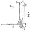
- Figure 4 is a schematic diagram of an inflator according to another embodiment of the present invention.
- Figure 5 is a schematic diagram of an inflatable system according to another embodiment of the present invention.
- Figure 2 shows an inflator according to a preferred embodiment of the present invention.
- inflator 200 includes a distributed charge 202 and a housing 204.
- Distributed charge 202 is designed to be installed within and distributed along the interior of the undeployed inflatable component of an inflatable system.
- Housing 204 includes a combustion chamber 210 and a gas storage chamber 220:
- Combustion chamber 210 includes an initiator 222, connector pins 224 and a gas propellant 226.
- Initiator 222 may be an electronic squib, such as the electronic squib used to initiate deployment of an automotive airbag.
- Connector pins 224 are used to electrically connect inflator 200 to a crash sensor or other activator.
- Gas propellant 226 may be pyrotechnic materials, such as boron potassium nitrate (BKNO 3 ).
- Gas storage chamber 220 includes an inert gas, such as argon, nitrogen or helium, at pressure in the range of about 134 bar to about 268 bar (about 2000 to about 4000 psi).
- Housing 204 also includes a gas nozzle 230.
- Distributed charge 202 is connected to housing 204.
- distributed charge 202 is connected to gas storage chamber 220 of housing 204 so that gas storage chamber 220 is in direct fluid communication with distributed charge 202 through gas nozzle 230.
- Distributed charge 202 may be mechanically joined to housing 204 by ferrule 250. Ferrule 250 also controls flow of the gas from gas storage chamber 220 to distributed charge 202.
- Distributed charge 202 can be a solid monolithic rod of pyrotechnic materials formed into the desired configuration using binders.
- distributed charge 202 can be enclosed in a sheath 203 (or layer or coating) for environmental protection.
- Inflator 200 can also include an end cap seal 216.
- End cap seal 216 for example, can be in the form of an o-ring, a gasket or other appropriate form which serves to seal against moisture and contamination.
- End cap seal 216 can be made of rubber, RTV and/or metals.
- the distributed charge may be a mixture of ammonium, guadinium, and/or triaminoguadinium salts of decahydrodecaboric acid and inorganic oxidizers such as ammonium nitrate and/or potassium nitrate.
- Representative compositions include about 5% to about 30% by weight of the decahydrodecaborate salt and about 70% to about 90% by weight of the nitrate salt.
- the additional materials may be used to coat, wrap, tape, or sheath the base distributed charge prior to installation of the overall distributed charge inflator in an inflatable system.
- the distributed charge may be an ITLX which is a simple, extruded product for linear ignition.
- the distributed charge can include a core of ignition material and a sheath.
- distributed charge may include a gas generating layer or coating.
- Ignition material is a moldable, formable, or extrudable rapidly burning pyrotechnic material, such as hydroborate fuel with various nitrate oxidizers (e.g., Rapid Deflagrating Cord (RDC) manufactured by Teledyne McCormick-Selph, Inc.), or secondary explosives loaded into a metal sheath (e.g., Mild Detonating Fuse (MDF), also known as Low Energy Detonating Cord or LEDC, manufactured by the Ensign Bickford Company of Simsbury, Conn.), as disclosed in the U.S. Patent No. 6,062,143 .
- RDC Rapid Deflagrating Cord
- MDF Mild Detonating Fuse
- LEDC Low Energy Detonating Cord
- Materials for the optional gas-generating layer or coating include alkali metal azides and organic azides with polymer binders, oxidizers, and metals used as the coating sheath or binder.
- alkali metal azides and organic azides with polymer binders, oxidizers, and metals used as the coating sheath or binder.
- one possible composition for a particular application might be a mixture of about 20% to about 50% by weight sodium azide, about 25% to about 35% by weight of potassium nitrate, about 10% to about 15% by weight of a fluoroelastomer binder, and about 15% to about 25% by weight of magnesium.
- energetic propellants and explosives can also be added to the distributed charge composition or to the coating or wrapping.
- BTTN butanetriol trinitrate
- PETN pentaerythritol tetranitrate
- RDX cyclotrimethylene trinitramine
- HMX cycloteramethylene tetranitramine
- MTN metriol trinitrate
- trinitrotoluene nitroglycerine
- inorganic oxidizers hexanitrostilbene (HNS), dipicramid (DIPAM), or inorganic oxidizers such as potassium nitrate, with metals such as magnesium
- HNS hexanitrostilbene
- DIPAM dipicramid
- inorganic oxidizers such as potassium nitrate, with metals such as magnesium
- Polymer binders which may be used to bind the distributed charge include: fluoroelastomers, crosslinked polybutadiene rubber, crosslinked polyacrylic rubber, crosslinked polyurethane elastomers, and polyvinyl alcohol/acetate.
- Energetic or gas-generating polymers which may be employed in the distributed charge assembly include: glycidyl nitrate polymers, glycidyl azide polymer, polytetrazoles, polytriazoles, nitrocellulose, dinitropolystyrene, nitrated polybutadienes, and nitrated polyethers.
- the environmentally-sealed sheath enclosing the distributed charge may be fabricated from ductile, easily extrudable metals such as tin (preferably) or silver, antimony or copper, or plastics such as polyethylene, polyurethane elastomer or fluoroelastomers.
- the sheath is designed to encapsulate and protect the energetic gas-generating materials to allow uniform vaporization or burning.
- the sheath splits open or vaporizes following the ignition of the distributed charge.
- the distributed charge, the gas generating layer, and the sheath can be formed into a wide variety of shapes and sizes to suit the specific application.
- Inflator 200 receives an electric signal when a crash sensor or other activator determines that the inflatable component must be deployed.
- initiator 222 ignites gas propellant 226 in combustion chamber 210.
- gas propellant 226 As pressure in combustion chamber 210 rises and exceeds the pressure of gas storage chamber 220, hot gas and hot particles from the burning gas propellant and the initiator flow into gas storage chamber 220.
- the hot gas and hot particles from combustion chamber 210 heat the compressed inert gas and cause a rapid pressure rise in gas storage chamber 220.
- the heated, compressed gas in gas storage chamber 220 flows through gas nozzle 230 and ignites distributed charge 202. Combustion of distributed charge 202 generates a high volume of gas which inflates an inflatable component of an inflatable system, such as an airbag.
- the distributed charge may be manufactured in various sizes and configurations, depending upon the inflation requirements of the system for which it is intended. These may range from a foil or thin film, or linear or tubular shaped charges to broad flat sheets of distributed charge material which may be cut, trimmed, or otherwise fitted.
- the distributed charge material whether in a linear or sheet form, may, in cross-section, be circular, wedge-shaped, diamond-shaped, "L" shaped, or formed in any number of other configurations. Because of this flexibility and the inherent simplicity of the invention, the distributed charge inflator is easier to install and less expensive to manufacture than gas generator systems currently in use.
- the distributed charge inflator can be designed so that, depending on the pattern of distribution of the distributed charge within a given inflatable system, the rate at which different distributed charge sections are ignited, and the number or location of the electronic squib used to ignite the material, variable inflation rates and effective total gas volumes may be achieved.
- the materials used for the distributed charge should be flexible and pliable, such that they will not fracture or flow under normal operating conditions.
- Figure 3 shows an inflatable system according to another preferred embodiment of the present invention.
- inflatable system 300 includes an inflatable component 340, a housing 304 and multiple strands of distributed charge 302A, 302B and 302C.
- Inflatable component 340 includes multiple inflatable chambers 340A, 340B and 340C. Each of the multiple strands of distributed charge 302A, 302B and 302C is distributed within each of the multiple inflatable chambers 340A, 340B and 340C, respectively.
- Housing 304 includes a combustion chamber 310 and a gas storage chamber 320.
- Combustion chamber 310 includes an initiator 322, connector pins 324 and a gas propellant 326.
- Gas storage chamber 320 includes an inert gas at a high pressure.
- Housing 304 also includes a gas nozzle 330.
- the multiple strands of distributed charge are connected to housing 304.
- multiple strands of distributed charge are connected to gas storage chamber 320 of housing 304 so that gas storage chamber 320 is in direct fluid communication with the multiple strands of distributed charge through gas nozzle 330.
- the multiple strands of distributed charge may be mechanically joined to housing 304 by a ferrule 350.
- initiator 322 Upon receiving an electrical signal from a crash sensor or other activator, initiator 322 ignites gas propellant 326 in combustion chamber 310.
- the hot gas and hot particles from the burning gas propellant and the initiator flow into gas storage chamber 320 and heat the compressed inert gas in gas storage chamber 320.
- the heated, compressed gas in gas storage chamber 320 flows through gas nozzle 330 and ignites multiple strands of distributed charge 302A, 302B and 302C. Combustion of each of the multiple strands of distributed charge 302A, 302B and 302C generates a high volume of gas and inflates each of the multiple inflatable chamber 340C, 340B and 340C, respectively, thus forming an inflated component with multiple inflated chambers.
- Figure 4 shows an inflator according to another preferred embodiment of the present invention.
- inflator 400 includes a housing 404 and a distributed charge 402.
- Housing 404 includes a combustion chamber 410 and a gas storage chamber 420.
- Combustion chamber 410 includes an initiator 422, connector pins 424 and a gas propellant 426.
- Gas storage chamber 420 includes an inert gas at a high pressure.
- Housing 404 also includes a gas nozzle 430.
- Distributed charge 402 is connected to housing 404.
- distributed charge 402 is connected to combustion chamber 410 of housing 404 so that combustion chamber 410 is in direct fluid communication with distributed charge 402 through gas nozzle 430.
- distributed charge 402 may be directly connected to initiator 422 in combustion chamber 410.
- Distributed charge 402 may be mechanically joined to housing 404 by a ferrule 450.
- initiator 422 Upon receiving an electrical signal from a crash sensor or other activator, initiator 422 ignites gas propellant 426 in combustion chamber 410 and distributed charge 402, causing the inflation of an inflatable component, such as an airbag. Simultaneously, the hot gas and hot particles from the burning gas propellant and the initiator flow into gas storage chamber 420. The hot gas and hot particles from combustion chamber 410 heat the compressed inert gas and cause a rapid pressure rise in gas storage chamber 420. The heated, compressed gas in gas storage chamber 420 flows into combustion chamber 410 and through gas nozzle 430. The heated, compressed gas sustains the inflation of the inflatable component.
- Figure 5 shows an inflatable system according to yet another preferred embodiment of the present invention.
- inflatable system 500 includes an inflatable component 540, a housing 504 and multiple strands of distributed charge 502A, 502B and 502C.
- Inflatable component 540 includes multiple inflatable chambers 540A, 540B and 540C. Each of the multiple strands of distributed charge 502A, 502B and 502C is distributed within each of the multiple inflatable chambers 540A, 540B and 540C, respectively.
- Housing 504 includes a combustion chamber 510 and a gas storage chamber 520.
- Combustion chamber 510 includes an initiator 522, connector pins 524 and a gas propellant 526.
- Gas storage chamber 520 includes an inert gas at a high pressure.
- Housing 504 also includes a gas nozzle 530.
- the multiple strands of distributed charge are connected to housing 504.
- the multiple strands of distributed charge are connected to combustion chamber 510 of housing 504 so that combustion chamber 510 is in direct fluid communication with the multiple strands of distributed charge through the gas nozzle.
- the multiple strands of distributed charge may be directly connected to initiator 522 in combustion chamber 510.
- Multiple strands of distributed charge 502A, 502B and 502C are mechanically joined to housing 504 by a ferrule 550.
- initiator 522 ignites gas propellant 526 in combustion chamber 510 and multiple strands of distributed charge 502A, 502B and 502C, thus forming an inflated component with multiple inflated chambers.
- the hot gas and hot particles from the burning gas propellant and the initiator flow into gas storage chamber 520 and heat the compressed inert gas in gas storage chamber 520.
- the heated, compressed gas in gas storage chamber 520 flows into combustion chamber 510 and flows through gas nozzle 530.
- the heated, compressed gas from gas storage chamber 520 sustains the inflation of the multiple inflatable chambers.
- the inflator in the present invention uses a distributed charge with a combination of pyrotechnic and stored gas.
- conventional compressed-gas inflator can be used with a distributed charge.
Landscapes
- Engineering & Computer Science (AREA)
- Chemical & Material Sciences (AREA)
- Mechanical Engineering (AREA)
- Physics & Mathematics (AREA)
- Fluid Mechanics (AREA)
- Chemical Kinetics & Catalysis (AREA)
- Combustion & Propulsion (AREA)
- Organic Chemistry (AREA)
- Air Bags (AREA)
- Feeding, Discharge, Calcimining, Fusing, And Gas-Generation Devices (AREA)
- Catching Or Destruction (AREA)
Claims (23)
- Aufblasbares System mit einer aufblasbaren Komponente, einer innerhalb der aufblasbaren Komponente zum Generieren eines sich ausdehnenden Gases verteilten Ladung (202; 402), einem Gehäuse (204; 304; 404; 504), und einem Zünder (222; 322; 422; 522), dadurch gekennzeichnet, dass das Gehäuse (204; 304; 404; 504) eine erste Kammer (210; 310; 410; 510) und eine zweite Kammer (220; 320; 420; 520) in Kommunikation mit der ersten Kammer aufweist, wobei die erste Kammer (210; 310; 410; 510) den Zünder (222; 422) und ein Gastreibmittel (226; 326; 426; 526) aufweist, und die zweite Kammer (220; 420) ein komprimiertes Gas enthält, und dass die Ladung (202; 402) an dem Gehäuse (204; 404) angeschlossen ist.
- System nach Anspruch 1, dadurch gekennzeichnet, dass die Ladung (402) an der ersten Kammer (410) angeschlossen ist.
- System nach Anspruch 2, dadurch gekennzeichnet, dass die Ladung (402) in direkter Fluidkommunikation mit der ersten Kammer (410) steht.
- System nach Anspruch 1, dadurch gekennzeichnet, dass die Ladung (202) an der zweiten Kammer (220) angeschlossen ist.
- System nach Anspruch 4, dadurch gekennzeichnet, dass die Ladung (202) in direkter Fluidkommunikation mit der zweiten Kammer (220) steht.
- System nach Anspruch 1, dadurch gekennzeichnet, dass die Ladung (402) an dem Zünder (422) angeschlossen ist.
- System nach Anspruch 1, dadurch gekennzeichnet, dass der Zünder (422) das Gastreibmittel (426) und die Ladung (402) zündet.
- System nach Anspruch 1, dadurch gekennzeichnet, dass der Zünder (222; 322; 422; 522) das Gastreibmittel (226; 326; 426; 526) in der ersten Kammer (210; 310; 410; 510) zündet und das gezündete Gastreibmittel (226; 326; 426; 526) das komprimierte Gas in der zweiten Kammer (220; 320; 420; 520) erwärmt.
- System nach Anspruch 8, dadurch gekennzeichnet, dass das erwärmte, komprimierte Gas zu einem Aufblasen der aufblasbaren Komponente führt.
- System nach Anspruch 8, dadurch gekennzeichnet, dass das erwärmte, komprimierte Gas die Ladung zündet.
- System nach Anspruch 5, dadurch gekennzeichnet, dass das Zünden der Ladung und des Gastreibmittels die aufblasbare Komponente aufbläst und das komprimierte Gas erwärmt, und dann das erwärmte, komprimierte Gas zu einem Aufblasen der aufblasbaren Komponente führt.
- System nach Anspruch 1, dadurch gekennzeichnet, dass die Ladung (202) von einem Mantel (203) umschlossen ist.
- System nach Anspruch 1, dadurch gekennzeichnet, dass die Ladung (202) aus einem Stab pyrotechnischen Materials gefertigt ist.
- System nach Anspruch 1, dadurch gekennzeichnet, dass das System eine Mehrzahl an Ladungen (302A, 302B, 302C; 502A, 502B, 502C) aufweist, die innerhalb der aufblasbaren Komponente (340; 540) zum Generieren des entfaltenden Gases verteilt sind.
- System nach Anspruch 14, dadurch gekennzeichnet, dass die Mehrzahl von Ladungen (302A, 302B, 302C; 502A, 502B, 502C) an dem Gehäuse (304; 504) angeschlossen sind.
- System nach Anspruch 14, dadurch gekennzeichnet, dass die Mehrzahl von Ladungen (502A, 502B, 502C) an der ersten Kammer (510) angeschlossen sind.
- System nach Anspruch 14, dadurch gekennzeichnet, dass die Mehrzahl von Ladungen (302A, 302B, 302C) an der zweiten Kammer (320) angeschlossen sind.
- System nach Anspruch 14, dadurch gekennzeichnet, dass die Mehrzahl von Ladungen (502A, 502B, 502C) an dem Zünder (522) angeschlossen sind.
- System nach Anspruch 14, dadurch gekennzeichnet, dass die aufblasbare Komponente (340; 540) eine Mehrzahl an aufblasbaren Kammern (340A, 340B, 340C; 540A, 540B, 540C) aufweist.
- System nach Anspruch 19, dadurch gekennzeichnet, dass jede der mehreren Ladungen (302A, 302B, 302C; 502A, 502B, 502C) innerhalb einer jeweiligen Kammer der mehreren aufblasbaren Kammern (340A, 340B, 340C; 540A, 540B, 540C) verteilt ist.
- System nach Anspruch 20, dadurch gekennzeichnet, dass jede der mehreren Ladungen die jeweilige Kammer der mehreren aufblasbaren Kammern aufbläst.
- System nach Anspruch 21, dadurch gekennzeichnet, dass die Ladung mechanisch an dem Gehäuse mittels einer Pressklemme verbunden ist.
- System nach Anspruch 1, dadurch gekennzeichnet, dass die zweite Kammer (220) ferner eine Gasdüse (230) aufweist, wobei die Ladung an dem Gehäuse durch die Gasdüse angeschlossen ist, wobei auf Erhalt eines elektrischen Signals von einem Aktivator der Zünder das Gastreibmittel in der ersten Kammer zündet, und dann das gezündete Gastreibmittel in die zweite Kammer strömt und das inerte Gas in der zweiten Kammer erwärmt, und dann das erwärmte inerte Gas in der zweiten Kammer durch die Gasdüse strömt und die Ladung zum Aufblasen der aufblasbaren Komponente zündet.
Applications Claiming Priority (5)
| Application Number | Priority Date | Filing Date | Title |
|---|---|---|---|
| US146933 | 2002-05-17 | ||
| US10/146,933 US6886469B2 (en) | 2002-05-17 | 2002-05-17 | Distributed charge inflator system |
| US10/224,435 US7162958B2 (en) | 2002-05-17 | 2002-08-21 | Distributed charge inflator system |
| US224435 | 2002-08-21 | ||
| PCT/US2003/015278 WO2003097382A2 (en) | 2002-05-17 | 2003-05-16 | Distributed charge inflator system |
Publications (3)
| Publication Number | Publication Date |
|---|---|
| EP1509409A2 EP1509409A2 (de) | 2005-03-02 |
| EP1509409A4 EP1509409A4 (de) | 2006-05-24 |
| EP1509409B1 true EP1509409B1 (de) | 2007-07-11 |
Family
ID=29552720
Family Applications (1)
| Application Number | Title | Priority Date | Filing Date |
|---|---|---|---|
| EP03728935A Expired - Lifetime EP1509409B1 (de) | 2002-05-17 | 2003-05-16 | Aufblassystem mit verteilter ladung |
Country Status (9)
| Country | Link |
|---|---|
| US (1) | US7162958B2 (de) |
| EP (1) | EP1509409B1 (de) |
| JP (1) | JP2005525963A (de) |
| KR (1) | KR100665766B1 (de) |
| AT (1) | ATE366673T1 (de) |
| AU (1) | AU2003234593A1 (de) |
| DE (1) | DE60314873T2 (de) |
| ES (1) | ES2290463T3 (de) |
| WO (1) | WO2003097382A2 (de) |
Cited By (1)
| Publication number | Priority date | Publication date | Assignee | Title |
|---|---|---|---|---|
| US10604259B2 (en) | 2016-01-20 | 2020-03-31 | Amsafe, Inc. | Occupant restraint systems having extending restraints, and associated systems and methods |
Families Citing this family (9)
| Publication number | Priority date | Publication date | Assignee | Title |
|---|---|---|---|---|
| US7188567B1 (en) | 1999-11-12 | 2007-03-13 | Zodiac Automotive Us Inc. | Gas generation system |
| US7162958B2 (en) | 2002-05-17 | 2007-01-16 | Zodiac Automotive Us Inc. | Distributed charge inflator system |
| US7137341B2 (en) * | 2002-05-17 | 2006-11-21 | Zodiac Automotive Us Inc. | Distributed charge inflator system |
| US20060157960A1 (en) * | 2004-12-22 | 2006-07-20 | Daicel Chemical Industries, Ltd. | Gas generator for air bag |
| JP4643283B2 (ja) * | 2005-01-28 | 2011-03-02 | ダイセル化学工業株式会社 | エアバッグ用ガス発生器 |
| JP4963917B2 (ja) * | 2005-09-30 | 2012-06-27 | 豊田合成株式会社 | ガス発生器 |
| US7882775B2 (en) * | 2007-08-07 | 2011-02-08 | Engineering Science Analysis Corporation | Non-lethal restraint device with diverse deployability applications |
| US9156558B2 (en) | 2011-04-05 | 2015-10-13 | Amsafe, Inc. | Inflatable personal restraint systems |
| US9440615B2 (en) * | 2014-12-10 | 2016-09-13 | Autoliv Asp, Inc. | Initiator assemblies |
Family Cites Families (114)
| Publication number | Priority date | Publication date | Assignee | Title |
|---|---|---|---|---|
| US3532359A (en) * | 1968-07-22 | 1970-10-06 | Chrysler Corp | Inflatable device |
| US3606377A (en) | 1968-11-04 | 1971-09-20 | Eaton Yale & Towne | Vehicle crash restraint system |
| CA935457A (en) | 1970-02-18 | 1973-10-16 | Kurokawa Isao | Gas-producing device for an inflatable body-protecting bag on a high-speed vehicle |
| DE2029587A1 (de) | 1970-06-16 | 1971-12-23 | Klippan Gmbh, 2000 Hamburg | Luftkissen für Kraftfahrzeuge zur Unfallverhütung bei Zusammenstößen |
| US3698183A (en) * | 1971-06-01 | 1972-10-17 | Us Army | Initiator booster |
| JPS5148714B2 (de) | 1972-05-20 | 1976-12-22 | ||
| JPS49120332A (de) | 1973-03-27 | 1974-11-18 | ||
| US4139404A (en) * | 1975-07-02 | 1979-02-13 | Teledyne Mccormick Selph | Active binder propellants incorporating burning rate catalysts |
| SE7703125L (sv) * | 1976-03-29 | 1977-09-30 | Allied Chem | Pyroteknisk uppblasningsanordning |
| JPS5916980B2 (ja) * | 1976-07-29 | 1984-04-18 | ダイセル化学工業株式会社 | ガスバツグ用ガス発生器 |
| US4164513A (en) * | 1977-11-22 | 1979-08-14 | Teledyne McCormick Selph, an operating div. of Teledyne Ind., Inc. | Amino-substituted guanidine salts of decahydrodecaboric acid |
| US4722551A (en) * | 1987-03-19 | 1988-02-02 | Morton Thiokol, Inc. | Initiator and method for the incorporation thereof in an inflator |
| JPH01151066A (ja) | 1987-12-09 | 1989-06-13 | Matsushita Electric Ind Co Ltd | テープレコーダ |
| US4902036A (en) * | 1988-01-19 | 1990-02-20 | Talley Automotive Products, Inc. | Deflector ring for use with inflators with passive restraint devices |
| JP2612742B2 (ja) * | 1988-04-20 | 1997-05-21 | 本田技研工業株式会社 | 乗員保護用エアバック装置 |
| JPH01273748A (ja) | 1988-04-26 | 1989-11-01 | Asahi Chem Ind Co Ltd | エアバッグ式乗員保護装置 |
| US4923212A (en) * | 1988-08-17 | 1990-05-08 | Talley Automotive Products, Inc. | Lightweight non-welded inflator unit for automobile airbags |
| JPH0281747A (ja) | 1988-09-19 | 1990-03-22 | Asahi Chem Ind Co Ltd | エアクッション |
| US5290060A (en) * | 1992-12-14 | 1994-03-01 | Morton International, Inc. | Hybrid gas generator for air bag inflatable restraint systems |
| US4950458A (en) * | 1989-06-22 | 1990-08-21 | Morton International, Inc. | Passenger automotive restraint generator |
| DE3932576A1 (de) | 1989-09-29 | 1991-04-18 | Dornier Gmbh | Gaserzeuger |
| GB2242010B (en) * | 1990-03-15 | 1993-10-13 | Ici Plc | Low energy fuse |
| US4998751A (en) | 1990-03-26 | 1991-03-12 | Morton International, Inc. | Two-stage automotive gas bag inflator using igniter material to delay second stage ignition |
| US5078422A (en) | 1990-04-30 | 1992-01-07 | Oea, Inc. | Gas inflator apparatus |
| US5219178A (en) * | 1990-10-08 | 1993-06-15 | Nippon Koki Co., Ltd. | Air bag inflation gas generator |
| US5131680A (en) * | 1991-03-19 | 1992-07-21 | Trw Vehicle Safety Systems Inc. | Inflator assembly |
| DE4116879A1 (de) * | 1991-05-23 | 1992-11-26 | Diehl Gmbh & Co | Gaserzeugendes modul fuer einen airbag von kraftfahrzeugen |
| DE4126527A1 (de) * | 1991-08-10 | 1993-02-25 | Diehl Gmbh & Co | Gasgenerator fuer einen airbag |
| DE4126743A1 (de) | 1991-08-13 | 1993-02-18 | Guenter Herrmann | Aufprallschutzsystem |
| US5125684A (en) * | 1991-10-15 | 1992-06-30 | Hercules Incorporated | Extrudable gas generating propellants, method and apparatus |
| DE4134995C1 (en) | 1991-10-23 | 1993-03-18 | Guenter 8152 Feldkirchen-Westerham De Herrmann | Sideways impact protection device - has inflatable cushion which is mounted at side of vehicle with sensor that detects impacts to initiates inflation |
| US5249824A (en) * | 1991-11-19 | 1993-10-05 | Trw Inc. | Air bag structure and method of forming |
| JPH05185899A (ja) | 1992-01-10 | 1993-07-27 | Takata Kk | エアバッグ装置のインフレータ |
| US5358273A (en) * | 1992-03-09 | 1994-10-25 | Toyo Tire & Rubber Co., Ltd. | Inflatable bags for airbag passive restraint systems for driver and method for production thereof |
| DE4211672C2 (de) | 1992-04-07 | 1995-03-23 | Keiper Recaro Gmbh Co | Sicherheitsgurt für Fahrzeugsitze, insbesondere Kraftfahrzeugsitze |
| US5403035A (en) * | 1992-06-01 | 1995-04-04 | Oea, Inc. | Preparing air bag vehicle restraint device having cellulose containing sheet propellant |
| US5282648A (en) * | 1992-06-01 | 1994-02-01 | Simula Inc. | Inflatable body and head restraint system |
| SE9202078D0 (sv) * | 1992-07-06 | 1992-07-06 | Bergslagens Produktutveckling | Taendanordning foer gasgeneratorer |
| GB9216517D0 (en) * | 1992-08-04 | 1992-09-23 | Ici Plc | Pyrotechnic sheet material |
| US5443286A (en) * | 1992-10-09 | 1995-08-22 | Morton International, Inc. | Gas generator for vehicle occupant restraint system |
| WO1994014637A1 (en) * | 1992-12-28 | 1994-07-07 | Atlantic Research Corporation | Inflating crash bags |
| US5346254A (en) * | 1993-02-01 | 1994-09-13 | Trw Inc. | Inflator assembly |
| US5322322A (en) * | 1993-02-19 | 1994-06-21 | Simula Inc. | Side impact head strike protection system |
| US5464246A (en) * | 1993-02-19 | 1995-11-07 | Simula Inc. | Inflatable tubular cushions for crash protection of seated automobile occupants |
| US5480181A (en) * | 1993-02-19 | 1996-01-02 | Simula Inc. | Side impact head strike protection system |
| DE4307774A1 (de) * | 1993-03-12 | 1994-09-15 | Dynamit Nobel Ag | Anzündeinrichtung |
| US5364127A (en) * | 1993-06-11 | 1994-11-15 | Trw Inc. | Inflator assembly |
| US5397543A (en) | 1993-06-21 | 1995-03-14 | Automotive Systems Laboratory, Inc. | Gas generator |
| US5423384A (en) * | 1993-06-24 | 1995-06-13 | Olin Corporation | Apparatus for suppressing a fire |
| US5406889A (en) * | 1993-09-03 | 1995-04-18 | Morton International, Inc. | Direct laser ignition of ignition products |
| US5435594A (en) * | 1993-12-03 | 1995-07-25 | Trw Inc. | Dual air bag system for occupant restraint |
| US5496062A (en) * | 1994-02-16 | 1996-03-05 | Morton International, Inc. | Liquid-fueled device to combine the functions of a low pressure switch (LPS), squib, and gas generator |
| US5630618A (en) * | 1994-03-18 | 1997-05-20 | Oea, Inc. | Hybrid inflator with a valve |
| US5423570A (en) * | 1994-05-09 | 1995-06-13 | Morton International, Inc. | Hybrid inflator with tortuous delivery passage |
| US5483896A (en) * | 1994-07-12 | 1996-01-16 | Morton International, Inc. | Pyrotechnic inflator for an air bag |
| JP3316315B2 (ja) * | 1994-09-06 | 2002-08-19 | タカタ株式会社 | 助手席用エアバッグ装置 |
| US5516147A (en) * | 1994-10-12 | 1996-05-14 | Morton International, Inc. | Stamped metal toroidal hybrid gas generator with sliding piston |
| IL115634A0 (en) | 1994-10-25 | 1996-01-19 | Oea Inc | Hybrid inflator with a valve |
| JPH08156724A (ja) | 1994-12-07 | 1996-06-18 | Nichiyu Giken Kogyo Kk | エアバッグ装着車用の窓ガラス破壊具 |
| JP3779730B2 (ja) * | 1994-12-12 | 2006-05-31 | アトランティック・リサーチ・コーポレーション | 混成インフレータ |
| US5462307A (en) * | 1994-12-27 | 1995-10-31 | General Motors Corporation | Supplemental inflation restraint inflator |
| US5615914A (en) * | 1995-01-17 | 1997-04-01 | Olin Corporation | Inflatable metal bladders for automobile passenger protection |
| FR2730965B1 (fr) * | 1995-02-23 | 1997-04-04 | Livbag Snc | Generateur pyrotechnique de gaz pour coussin gonflable d'un vehicule automobile |
| US5623115A (en) * | 1995-05-30 | 1997-04-22 | Morton International, Inc. | Inflator for a vehicle airbag system and a pyrogen igniter used therein |
| WO1996040541A1 (en) | 1995-06-07 | 1996-12-19 | Takata Moses Lake, Inc. | Airbag inflator system |
| DE19520847B4 (de) | 1995-06-08 | 2005-08-18 | Honda Giken Kogyo K.K. | Vorrichtung zur Gaserzeugung für einen Kraftfahrzeug-Airbag |
| DE19526334A1 (de) | 1995-07-19 | 1997-01-23 | Bosch Gmbh Robert | Sicherheitseinrichtung für Fahrzeuginsassen |
| US5520413A (en) * | 1995-09-11 | 1996-05-28 | Morton International, Inc. | Partitioned multi-cell air bag |
| JP3789527B2 (ja) | 1995-10-06 | 2006-06-28 | 本田技研工業株式会社 | エアバッグ用ガス発生剤 |
| JPH09124389A (ja) | 1995-10-30 | 1997-05-13 | Nippon Oil & Fats Co Ltd | ガス発生剤組成物 |
| WO1997020786A1 (en) | 1995-12-01 | 1997-06-12 | Nippon Kayaku Kabushiki-Kaisha | Gas generating agent and transfer charge for use in airbag gas generator, and gas generator comprising said gas generating agent and transfer charge |
| US5613706A (en) * | 1995-12-13 | 1997-03-25 | Morton International, Inc. | Self-contained inflator pyrotechnic initiator |
| US5868424A (en) | 1996-03-06 | 1999-02-09 | Oea, Inc. | Substantially smoke-free and particulate-free inflator for inflatable safety restraint system |
| US5820162A (en) * | 1996-03-21 | 1998-10-13 | Airbelt Systems, Llc. | Airbag system inflator |
| JP3397041B2 (ja) * | 1996-03-28 | 2003-04-14 | 豊田合成株式会社 | 側突用エアバッグ |
| US5670738A (en) * | 1996-08-08 | 1997-09-23 | Morton International. Inc. | Hybrid inflator with pop-out diffuser |
| JP3760004B2 (ja) * | 1996-10-11 | 2006-03-29 | ダイセル化学工業株式会社 | エアバッグ用ガス発生器 |
| US5918900A (en) * | 1996-11-20 | 1999-07-06 | Breed Automotive Technology, Inc. | Hybrid inflator with bore and burst disk |
| US5890735A (en) * | 1997-01-13 | 1999-04-06 | Morton International Inc. | Hybrid inflator with diffuser end translating initiator boss |
| FR2760710B1 (fr) | 1997-03-14 | 1999-04-23 | Livbag Snc | Generateur pyrotechnique de gaz a debit et volume adaptables pour coussin de protection |
| DE19723260A1 (de) * | 1997-06-03 | 1998-12-10 | Temic Bayern Chem Airbag Gmbh | Gasgenerator |
| US5927748A (en) * | 1997-06-26 | 1999-07-27 | O'driscoll; Peter | Multi-stage inflatable bag for vehicular safety systems |
| EP0888932B1 (de) | 1997-07-04 | 2002-01-02 | Volkswagen Aktiengesellschaft | Verfahren und Einrichtung zur Auslösung des Airbagsystems bei einem Personenkraftwagen |
| US5860292A (en) | 1997-08-26 | 1999-01-19 | Augustine Medical, Inc. | Inflatable thermal blanket for convectively cooling a body |
| US6062143A (en) | 1997-09-08 | 2000-05-16 | Simula, Inc. | Distributed charge inflator system |
| US5967550A (en) | 1997-10-07 | 1999-10-19 | Trw Inc. | Staged pyrotechnic air bag inflator |
| US6066017A (en) | 1998-01-29 | 2000-05-23 | The United States Of America As Represented By The Secretary Of The Navy | Inflatable, noncollapsible, personal flotation device |
| AU2573399A (en) | 1998-02-03 | 1999-08-16 | Talley Defense Systems, Inc. | Very thin inflator and method of making and using same |
| US6032979C1 (en) | 1998-02-18 | 2001-10-16 | Autoliv Asp Inc | Adaptive output inflator |
| US6073961A (en) | 1998-02-20 | 2000-06-13 | Breed Automotive Technology, Inc. | Inflatable side airbag curtain module |
| US6019389A (en) | 1998-03-31 | 2000-02-01 | Trw Vehicle Safety Systems Inc. | Air bag inflator |
| US6106010A (en) | 1998-03-31 | 2000-08-22 | Trw Vehicle Safety Systems Inc. | Vehicle occupant protection system having a dual stage inflator |
| US6095559A (en) | 1998-07-23 | 2000-08-01 | Autoliv Asp, Inc. | Chemical cooling of airbag inflation gases |
| DE19843828B4 (de) * | 1998-09-24 | 2006-01-05 | Volkswagen Ag | Airbagsystem für Kraftfahrzeuge |
| US6017404A (en) * | 1998-12-23 | 2000-01-25 | Atlantic Research Corporation | Nonazide ammonium nitrate based gas generant compositions that burn at ambient pressure |
| US6227562B1 (en) | 1999-02-26 | 2001-05-08 | Trw Inc. | Stored gas inflator assembly |
| DE29907617U1 (de) | 1999-04-29 | 1999-09-16 | TRW Occupant Restraint Systems GmbH & Co. KG, 73553 Alfdorf | Gasgenerator und Vorrichtung zum Aufblasen eines Fahrzeuginsassen-Rückhaltesystems |
| JP2001047960A (ja) | 1999-07-16 | 2001-02-20 | Johnson Controls Technol Co | 膨張可能エアバッグを収容するためのアセンブリ及びその生産方法 |
| US6237950B1 (en) | 1999-07-26 | 2001-05-29 | Trw Vehicle Safety Systems Inc. | Staged air bag inflator |
| DE50004442D1 (de) * | 1999-08-16 | 2003-12-18 | Autoliv Dev | Kraftfahrzeug-gassackanordnung mit schnurgasgenerator |
| FR2799708B1 (fr) * | 1999-09-24 | 2001-12-07 | Livbag Snc | Structure metallique gonflable a chargement pyrotechnique integre |
| JP2003525106A (ja) | 1999-11-12 | 2003-08-26 | ジェネラル ダイナミクス オーティエス(エアロスペース)、 インコーポレイテッド | ガス発生システム |
| DE20013405U1 (de) | 2000-08-03 | 2001-02-15 | Lell, Peter, Dr.-Ing., 85368 Moosburg | Mehrstufiger programmierbarer Gasgenerator, insbesondere für Kfz-Airbagsysteme |
| DE10040681C1 (de) | 2000-08-19 | 2001-09-13 | Autoliv Dev | Kraftfahrzeug mit einer an die Innenausstattung angebundenen Gassackeinrichtung |
| US6612243B1 (en) * | 2001-02-27 | 2003-09-02 | Aerojet - General Corporation | Fire extinguisher |
| FR2831122B1 (fr) | 2001-10-19 | 2004-07-30 | Livbag Snc | Dispositif generateur de gaz hybride pour gonfler un coussin de protection utilise en securite automobile |
| FR2831123B1 (fr) | 2001-10-19 | 2004-07-30 | Livbag Snc | Dispositif generateur de gaz hybride utilise en securite automobile pour gonfler un coussin de protection lateral |
| US6755438B2 (en) * | 2001-10-22 | 2004-06-29 | Autoliv Asp, Inc. | Elongated inflator device and method of gas production |
| US6854764B2 (en) * | 2002-02-20 | 2005-02-15 | Autoliv Asp, Inc. | Flexible airbag inflator |
| US6746046B2 (en) * | 2002-03-19 | 2004-06-08 | Autoliv Asp, Inc. | Dual flow inflator for a vehicular airbag system |
| US6820898B2 (en) * | 2002-03-19 | 2004-11-23 | Autoliv Asp, Inc. | Biaxial dual stage inflator with extended gas delivery for a vehicular airbag system |
| US7137341B2 (en) | 2002-05-17 | 2006-11-21 | Zodiac Automotive Us Inc. | Distributed charge inflator system |
| US6886469B2 (en) * | 2002-05-17 | 2005-05-03 | Zodiac Automotive Us Inc. | Distributed charge inflator system |
| US7162958B2 (en) | 2002-05-17 | 2007-01-16 | Zodiac Automotive Us Inc. | Distributed charge inflator system |
-
2002
- 2002-08-21 US US10/224,435 patent/US7162958B2/en not_active Expired - Fee Related
-
2003
- 2003-05-16 AU AU2003234593A patent/AU2003234593A1/en not_active Abandoned
- 2003-05-16 EP EP03728935A patent/EP1509409B1/de not_active Expired - Lifetime
- 2003-05-16 JP JP2004504745A patent/JP2005525963A/ja active Pending
- 2003-05-16 AT AT03728935T patent/ATE366673T1/de not_active IP Right Cessation
- 2003-05-16 WO PCT/US2003/015278 patent/WO2003097382A2/en not_active Ceased
- 2003-05-16 DE DE60314873T patent/DE60314873T2/de not_active Expired - Lifetime
- 2003-05-16 KR KR1020047018507A patent/KR100665766B1/ko not_active Expired - Fee Related
- 2003-05-16 ES ES03728935T patent/ES2290463T3/es not_active Expired - Lifetime
Non-Patent Citations (1)
| Title |
|---|
| None * |
Cited By (1)
| Publication number | Priority date | Publication date | Assignee | Title |
|---|---|---|---|---|
| US10604259B2 (en) | 2016-01-20 | 2020-03-31 | Amsafe, Inc. | Occupant restraint systems having extending restraints, and associated systems and methods |
Also Published As
| Publication number | Publication date |
|---|---|
| EP1509409A2 (de) | 2005-03-02 |
| AU2003234593A1 (en) | 2003-12-02 |
| WO2003097382A3 (en) | 2004-04-29 |
| ES2290463T3 (es) | 2008-02-16 |
| JP2005525963A (ja) | 2005-09-02 |
| US20030213398A1 (en) | 2003-11-20 |
| ATE366673T1 (de) | 2007-08-15 |
| DE60314873D1 (de) | 2007-08-23 |
| DE60314873T2 (de) | 2008-03-13 |
| EP1509409A4 (de) | 2006-05-24 |
| US7162958B2 (en) | 2007-01-16 |
| WO2003097382A2 (en) | 2003-11-27 |
| KR20050083571A (ko) | 2005-08-26 |
| KR100665766B1 (ko) | 2007-01-09 |
Similar Documents
| Publication | Publication Date | Title |
|---|---|---|
| EP0941180B2 (de) | Aufblasvorrichtung mit verteilter ladung | |
| EP0825074B1 (de) | Airbag-Aufblasvorrichtung | |
| EP1945597B1 (de) | Gaserzeugende zusammensetzung | |
| WO1999008983A1 (en) | Ignition enhancement composition for an airbag inflator | |
| US7162958B2 (en) | Distributed charge inflator system | |
| US6886469B2 (en) | Distributed charge inflator system | |
| WO2000032447A9 (en) | Pyrotechnic inflator for a vehicle | |
| US6368431B2 (en) | Air bag inflator | |
| KR100500808B1 (ko) | 기체 발생기의 자동 점화 | |
| US20030226468A1 (en) | Distributed charge inflator system | |
| US7188567B1 (en) | Gas generation system | |
| WO1999038725A2 (en) | Thin inflator and azide polymer composition thereof | |
| MXPA99004284A (es) | Sistema inflador de carga distribuida |
Legal Events
| Date | Code | Title | Description |
|---|---|---|---|
| PUAI | Public reference made under article 153(3) epc to a published international application that has entered the european phase |
Free format text: ORIGINAL CODE: 0009012 |
|
| 17P | Request for examination filed |
Effective date: 20041208 |
|
| AK | Designated contracting states |
Kind code of ref document: A2 Designated state(s): AT BE BG CH CY CZ DE DK EE ES FI FR GB GR HU IE IT LI LU MC NL PT RO SE SI SK TR |
|
| AX | Request for extension of the european patent |
Extension state: AL LT LV MK |
|
| DAX | Request for extension of the european patent (deleted) | ||
| A4 | Supplementary search report drawn up and despatched |
Effective date: 20060406 |
|
| 17Q | First examination report despatched |
Effective date: 20060907 |
|
| GRAP | Despatch of communication of intention to grant a patent |
Free format text: ORIGINAL CODE: EPIDOSNIGR1 |
|
| GRAS | Grant fee paid |
Free format text: ORIGINAL CODE: EPIDOSNIGR3 |
|
| GRAA | (expected) grant |
Free format text: ORIGINAL CODE: 0009210 |
|
| AK | Designated contracting states |
Kind code of ref document: B1 Designated state(s): AT BE BG CH CY CZ DE DK EE ES FI FR GB GR HU IE IT LI LU MC NL PT RO SE SI SK TR |
|
| REG | Reference to a national code |
Ref country code: GB Ref legal event code: FG4D |
|
| REG | Reference to a national code |
Ref country code: CH Ref legal event code: EP |
|
| REF | Corresponds to: |
Ref document number: 60314873 Country of ref document: DE Date of ref document: 20070823 Kind code of ref document: P |
|
| REG | Reference to a national code |
Ref country code: IE Ref legal event code: FG4D |
|
| REG | Reference to a national code |
Ref country code: SE Ref legal event code: TRGR |
|
| ET | Fr: translation filed | ||
| PG25 | Lapsed in a contracting state [announced via postgrant information from national office to epo] |
Ref country code: PT Free format text: LAPSE BECAUSE OF FAILURE TO SUBMIT A TRANSLATION OF THE DESCRIPTION OR TO PAY THE FEE WITHIN THE PRESCRIBED TIME-LIMIT Effective date: 20071211 Ref country code: FI Free format text: LAPSE BECAUSE OF FAILURE TO SUBMIT A TRANSLATION OF THE DESCRIPTION OR TO PAY THE FEE WITHIN THE PRESCRIBED TIME-LIMIT Effective date: 20070711 Ref country code: BG Free format text: LAPSE BECAUSE OF FAILURE TO SUBMIT A TRANSLATION OF THE DESCRIPTION OR TO PAY THE FEE WITHIN THE PRESCRIBED TIME-LIMIT Effective date: 20071011 Ref country code: NL Free format text: LAPSE BECAUSE OF FAILURE TO SUBMIT A TRANSLATION OF THE DESCRIPTION OR TO PAY THE FEE WITHIN THE PRESCRIBED TIME-LIMIT Effective date: 20070711 |
|
| REG | Reference to a national code |
Ref country code: CH Ref legal event code: PL |
|
| NLV1 | Nl: lapsed or annulled due to failure to fulfill the requirements of art. 29p and 29m of the patents act | ||
| REG | Reference to a national code |
Ref country code: ES Ref legal event code: FG2A Ref document number: 2290463 Country of ref document: ES Kind code of ref document: T3 |
|
| PG25 | Lapsed in a contracting state [announced via postgrant information from national office to epo] |
Ref country code: AT Free format text: LAPSE BECAUSE OF FAILURE TO SUBMIT A TRANSLATION OF THE DESCRIPTION OR TO PAY THE FEE WITHIN THE PRESCRIBED TIME-LIMIT Effective date: 20070711 Ref country code: CH Free format text: LAPSE BECAUSE OF FAILURE TO SUBMIT A TRANSLATION OF THE DESCRIPTION OR TO PAY THE FEE WITHIN THE PRESCRIBED TIME-LIMIT Effective date: 20070711 Ref country code: LI Free format text: LAPSE BECAUSE OF FAILURE TO SUBMIT A TRANSLATION OF THE DESCRIPTION OR TO PAY THE FEE WITHIN THE PRESCRIBED TIME-LIMIT Effective date: 20070711 |
|
| PG25 | Lapsed in a contracting state [announced via postgrant information from national office to epo] |
Ref country code: BE Free format text: LAPSE BECAUSE OF FAILURE TO SUBMIT A TRANSLATION OF THE DESCRIPTION OR TO PAY THE FEE WITHIN THE PRESCRIBED TIME-LIMIT Effective date: 20070711 |
|
| PG25 | Lapsed in a contracting state [announced via postgrant information from national office to epo] |
Ref country code: GR Free format text: LAPSE BECAUSE OF FAILURE TO SUBMIT A TRANSLATION OF THE DESCRIPTION OR TO PAY THE FEE WITHIN THE PRESCRIBED TIME-LIMIT Effective date: 20071012 Ref country code: DK Free format text: LAPSE BECAUSE OF FAILURE TO SUBMIT A TRANSLATION OF THE DESCRIPTION OR TO PAY THE FEE WITHIN THE PRESCRIBED TIME-LIMIT Effective date: 20070711 |
|
| PLBE | No opposition filed within time limit |
Free format text: ORIGINAL CODE: 0009261 |
|
| STAA | Information on the status of an ep patent application or granted ep patent |
Free format text: STATUS: NO OPPOSITION FILED WITHIN TIME LIMIT |
|
| PG25 | Lapsed in a contracting state [announced via postgrant information from national office to epo] |
Ref country code: SK Free format text: LAPSE BECAUSE OF FAILURE TO SUBMIT A TRANSLATION OF THE DESCRIPTION OR TO PAY THE FEE WITHIN THE PRESCRIBED TIME-LIMIT Effective date: 20070711 Ref country code: CZ Free format text: LAPSE BECAUSE OF FAILURE TO SUBMIT A TRANSLATION OF THE DESCRIPTION OR TO PAY THE FEE WITHIN THE PRESCRIBED TIME-LIMIT Effective date: 20070711 |
|
| 26N | No opposition filed |
Effective date: 20080414 |
|
| PG25 | Lapsed in a contracting state [announced via postgrant information from national office to epo] |
Ref country code: RO Free format text: LAPSE BECAUSE OF FAILURE TO SUBMIT A TRANSLATION OF THE DESCRIPTION OR TO PAY THE FEE WITHIN THE PRESCRIBED TIME-LIMIT Effective date: 20070711 |
|
| PG25 | Lapsed in a contracting state [announced via postgrant information from national office to epo] |
Ref country code: MC Free format text: LAPSE BECAUSE OF NON-PAYMENT OF DUE FEES Effective date: 20080531 |
|
| PG25 | Lapsed in a contracting state [announced via postgrant information from national office to epo] |
Ref country code: EE Free format text: LAPSE BECAUSE OF FAILURE TO SUBMIT A TRANSLATION OF THE DESCRIPTION OR TO PAY THE FEE WITHIN THE PRESCRIBED TIME-LIMIT Effective date: 20070711 |
|
| PG25 | Lapsed in a contracting state [announced via postgrant information from national office to epo] |
Ref country code: IE Free format text: LAPSE BECAUSE OF NON-PAYMENT OF DUE FEES Effective date: 20080516 |
|
| PG25 | Lapsed in a contracting state [announced via postgrant information from national office to epo] |
Ref country code: SI Free format text: LAPSE BECAUSE OF FAILURE TO SUBMIT A TRANSLATION OF THE DESCRIPTION OR TO PAY THE FEE WITHIN THE PRESCRIBED TIME-LIMIT Effective date: 20070711 |
|
| PG25 | Lapsed in a contracting state [announced via postgrant information from national office to epo] |
Ref country code: CY Free format text: LAPSE BECAUSE OF FAILURE TO SUBMIT A TRANSLATION OF THE DESCRIPTION OR TO PAY THE FEE WITHIN THE PRESCRIBED TIME-LIMIT Effective date: 20070711 |
|
| PG25 | Lapsed in a contracting state [announced via postgrant information from national office to epo] |
Ref country code: HU Free format text: LAPSE BECAUSE OF FAILURE TO SUBMIT A TRANSLATION OF THE DESCRIPTION OR TO PAY THE FEE WITHIN THE PRESCRIBED TIME-LIMIT Effective date: 20080112 Ref country code: LU Free format text: LAPSE BECAUSE OF NON-PAYMENT OF DUE FEES Effective date: 20080516 |
|
| PG25 | Lapsed in a contracting state [announced via postgrant information from national office to epo] |
Ref country code: TR Free format text: LAPSE BECAUSE OF FAILURE TO SUBMIT A TRANSLATION OF THE DESCRIPTION OR TO PAY THE FEE WITHIN THE PRESCRIBED TIME-LIMIT Effective date: 20070711 |
|
| PGFP | Annual fee paid to national office [announced via postgrant information from national office to epo] |
Ref country code: ES Payment date: 20110617 Year of fee payment: 9 Ref country code: FR Payment date: 20110523 Year of fee payment: 9 Ref country code: SE Payment date: 20110512 Year of fee payment: 9 |
|
| PGFP | Annual fee paid to national office [announced via postgrant information from national office to epo] |
Ref country code: GB Payment date: 20110511 Year of fee payment: 9 |
|
| PGFP | Annual fee paid to national office [announced via postgrant information from national office to epo] |
Ref country code: IT Payment date: 20110524 Year of fee payment: 9 Ref country code: DE Payment date: 20110511 Year of fee payment: 9 |
|
| REG | Reference to a national code |
Ref country code: SE Ref legal event code: EUG |
|
| GBPC | Gb: european patent ceased through non-payment of renewal fee |
Effective date: 20120516 |
|
| PG25 | Lapsed in a contracting state [announced via postgrant information from national office to epo] |
Ref country code: SE Free format text: LAPSE BECAUSE OF NON-PAYMENT OF DUE FEES Effective date: 20120517 Ref country code: IT Free format text: LAPSE BECAUSE OF NON-PAYMENT OF DUE FEES Effective date: 20120516 |
|
| REG | Reference to a national code |
Ref country code: FR Ref legal event code: ST Effective date: 20130131 |
|
| REG | Reference to a national code |
Ref country code: DE Ref legal event code: R119 Ref document number: 60314873 Country of ref document: DE Effective date: 20121201 |
|
| PG25 | Lapsed in a contracting state [announced via postgrant information from national office to epo] |
Ref country code: GB Free format text: LAPSE BECAUSE OF NON-PAYMENT OF DUE FEES Effective date: 20120516 Ref country code: FR Free format text: LAPSE BECAUSE OF NON-PAYMENT OF DUE FEES Effective date: 20120531 |
|
| PG25 | Lapsed in a contracting state [announced via postgrant information from national office to epo] |
Ref country code: DE Free format text: LAPSE BECAUSE OF NON-PAYMENT OF DUE FEES Effective date: 20121201 |
|
| REG | Reference to a national code |
Ref country code: ES Ref legal event code: FD2A Effective date: 20130820 |
|
| PG25 | Lapsed in a contracting state [announced via postgrant information from national office to epo] |
Ref country code: ES Free format text: LAPSE BECAUSE OF NON-PAYMENT OF DUE FEES Effective date: 20120517 |