EP1503579A1 - Mise en place d'une section émettant de la lumière dans un dispositif de prise de vue - Google Patents
Mise en place d'une section émettant de la lumière dans un dispositif de prise de vue Download PDFInfo
- Publication number
- EP1503579A1 EP1503579A1 EP04017726A EP04017726A EP1503579A1 EP 1503579 A1 EP1503579 A1 EP 1503579A1 EP 04017726 A EP04017726 A EP 04017726A EP 04017726 A EP04017726 A EP 04017726A EP 1503579 A1 EP1503579 A1 EP 1503579A1
- Authority
- EP
- European Patent Office
- Prior art keywords
- light
- image sensing
- case member
- image
- image display
- Prior art date
- Legal status (The legal status is an assumption and is not a legal conclusion. Google has not performed a legal analysis and makes no representation as to the accuracy of the status listed.)
- Withdrawn
Links
Images


Classifications
-
- G—PHYSICS
- G03—PHOTOGRAPHY; CINEMATOGRAPHY; ANALOGOUS TECHNIQUES USING WAVES OTHER THAN OPTICAL WAVES; ELECTROGRAPHY; HOLOGRAPHY
- G03B—APPARATUS OR ARRANGEMENTS FOR TAKING PHOTOGRAPHS OR FOR PROJECTING OR VIEWING THEM; APPARATUS OR ARRANGEMENTS EMPLOYING ANALOGOUS TECHNIQUES USING WAVES OTHER THAN OPTICAL WAVES; ACCESSORIES THEREFOR
- G03B15/00—Special procedures for taking photographs; Apparatus therefor
- G03B15/02—Illuminating scene
- G03B15/03—Combinations of cameras with lighting apparatus; Flash units
- G03B15/05—Combinations of cameras with electronic flash apparatus; Electronic flash units
-
- H—ELECTRICITY
- H04—ELECTRIC COMMUNICATION TECHNIQUE
- H04M—TELEPHONIC COMMUNICATION
- H04M1/00—Substation equipment, e.g. for use by subscribers
- H04M1/02—Constructional features of telephone sets
- H04M1/0202—Portable telephone sets, e.g. cordless phones, mobile phones or bar type handsets
- H04M1/0206—Portable telephones comprising a plurality of mechanically joined movable body parts, e.g. hinged housings
- H04M1/0208—Portable telephones comprising a plurality of mechanically joined movable body parts, e.g. hinged housings characterized by the relative motions of the body parts
- H04M1/0214—Foldable telephones, i.e. with body parts pivoting to an open position around an axis parallel to the plane they define in closed position
- H04M1/0216—Foldable in one direction, i.e. using a one degree of freedom hinge
- H04M1/0218—The hinge comprising input and/or output user interface means
-
- H—ELECTRICITY
- H04—ELECTRIC COMMUNICATION TECHNIQUE
- H04N—PICTORIAL COMMUNICATION, e.g. TELEVISION
- H04N23/00—Cameras or camera modules comprising electronic image sensors; Control thereof
- H04N23/56—Cameras or camera modules comprising electronic image sensors; Control thereof provided with illuminating means
-
- H—ELECTRICITY
- H04—ELECTRIC COMMUNICATION TECHNIQUE
- H04M—TELEPHONIC COMMUNICATION
- H04M2250/00—Details of telephonic subscriber devices
- H04M2250/52—Details of telephonic subscriber devices including functional features of a camera
Definitions
- This invention relates to a structure for placement of a light-emitting section used in an image sensing apparatus to illuminate a subject.
- Figs. 11 to 13 illustrate examples of an image sensing apparatus in which the light-emitting section is always exposed externally for design reasons.
- Figs. 14 and 15 illustrate structures in which the light-emitting section usually is concealed within the main body of the image sensing apparatus and is exposed externally of the apparatus by automatic or manual operation when necessary.
- reference numerals 101, 111, 121, 131 and 141 each denote the main body of an image sensing apparatus
- reference numerals 102, 112, 122, 132 and 142 each denote an imaging lens
- reference numerals 103, 113, 123, 133 and 143 each denote a light-emitting section.
- the light-emitting section 103 in Fig. 11 is placed above the imaging lens 102 (for example, see the specification of Japanese Patent Application Laid-Open No. 2002-314865).
- the light-emitting section 113 in Fig. 12 is placed below a hinge mechanism 114 so adapted that an image display device 117 may be opened and closed freely relative to the main body 111 of the image sensing apparatus. Further, the light-emitting section 123 of Fig. 13 is placed below the imaging lens 122.
- the right hand 116 or 126 of the user comes into intimate contact with the front end face 115 or 125 of the main body 111 or 121 as illustrated in Fig. 12 or 13.
- the light-emitting section 133 in Fig. 14 is held by a member 136 so adapted that the light-emitting section 133 may be rotated freely in the directions of arrows 137 about a point 134.
- the holding member 136 is so designed that the light-emitting section 133 is situated at position b when it is concealed within the main body 131 of the image sensing apparatus and at position a when it is exposed.
- a similar arrangement is described in the specification of Japanese Patent Application Laid-Open No. 2002-250962.
- the light-emitting section 143 is held by a member 146 so adapted that the light-emitting section 143 may be rotated freely in the directions of arrows 147 about a point 144 in a manner similar to that of Fig. 14.
- the holding member 146 is so designed that the light-emitting section 143 is situated at position b when it is concealed within the main body 141 of the image sensing apparatus and at position a when it is exposed.
- Part of the imaging lens 142 is provided with a recess 145 in order to accommodate the holding member 146 at position b.
- the light-emitting section in the description above mainly is used when taking a still picture if it is referred to as an electronic flash and is used when shooting a moving picture if it is referred to as a video light.
- the present invention has been made in view of the above circumstances and its object is to improve operability when the light-emitting section is used for shooting a picture, while preventing an increase in the size of the image sensing apparatus as well as a rise in the cost thereof.
- an image sensing apparatus comprising: a main body of an image sensing apparatus enclosed by a first case member; an image sensing unit having an imaging lens and a solid-state image sensing device for converting light from a subject, which enters via the imaging lens, to an electric signal; a light-emitting device for emitting light toward the subject; an image display unit having an image display screen for displaying an image captured by the image sensing unit, and a second case member provided so as to enclose an outer frame of the image display screen; a rotating member for holding the main body of the image sensing apparatus and the image display unit rotatably relative to each other; and a third case member for internally accommodating the rotating member and the light-emitting device, the third case member being secured to the first case member and provided projectively with respect to the first case member, or being secured to the second case member and provided projectively with respect to the second case member.
- Fig. 1 Shown in Fig. 1 are the main body 1 of an image sensing apparatus, an imaging lens 2, a light-emitting section 3, an image display device (which generally employs an LCD panel) 6 and a case 7 that holds the image display device 6.
- the case 7 is attached to the main body 1 of the image sensing apparatus by a hinge portion 4 so as to be free to open and close.
- the light-emitting section 3 and the hinge portion 4 are incorporated within a case member 1b which is fixed on a case member 1a that is one surface of the main body 1, and extrudes from the case member 1a.
- Fig. 1 is a diagram illustrating the case 7 opened in the direction of arrow 12 with respect to the main body 1 of the image sensing apparatus.
- Reference numeral 5 denotes a white LED constituting a second light-emitting section. The LED 5 assists in illuminating a dimly lit subject by emitting light toward the subject. The LED 5 is used as auxiliary light when automatic focus and range adjustments are made and as a video light when a moving picture is shot.
- Reference numeral 8 denotes a second image display unit and 11 a microphone.
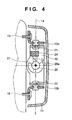
- the structure of the hinge portion 4, which includes the light-emitting section 3, will be described with reference to Figs. 2, 3 and 4.
- These structural components are held on the main body 1 of the image sensing apparatus by a holding member 19.
- bases 13a, 13b of the hinge mechanism are secured to the main body 1 by fastening parts 15, 16.
- a rotating member 20 adapted to be freely rotatable with respect to the bases 13a, 13b via rotary shaft members 21, 22 is secured to the case 7 of the image display device.
- Fig. 3 is a sectional view taken along line AA' of Fig. 2.
- the case 7 of the image display device is adapted so as to be rotatable about a rotary shaft 14, and the center of rotation of the rotary shaft members 21, 22 coincides with the rotary shaft 14.
- the case 7 of the image display device is free to rotate in the direction of arrow 12 about the rotary shaft 14.
- a detection switch 25 secured within the main body 1 detects a projection 29 provided on the case 7. Conversely, if the case 7 of the image display device is rotated in the direction opposite that of arrow 12a, the projection 29 departs from the detection switch 25 and is no longer sensed thereby. Thus, it is possible to detect whether the case 7 is in the opened or closed state.
- Fig. 4 is a sectional view taken along line BB' of Fig. 2. It is also possible to so arrange it that the case 7 of the image display device is free to rotate in the direction of arrow 28 about a rotary shaft 27 that perpendicularly intersects the rotary shaft 14. At this time the rotating member 20 and case 7 are coupled by a rotary shaft member 26. The central axis of rotation of the rotating member 20 coincides with the rotary shaft 27. In general, this rotation is used when the case 7 of the image display device is in the opened state with respect to the main body 1 of the image sensing apparatus.
- a detection switch 24 secured to the hinge detects a projection provided on the rotary shaft member 26.
- the projection departs from the detection switch 24 and is no longer sensed thereby.
- Fig. 6 is a block diagram illustrating the functional implementation of the image sensing apparatus. Shown in Fig. 6 are an imaging lens 301, an image sensing device 302, a signal processor 303, an image display device 304, a recording unit 305, a microcomputer 306 for control, a control panel 307, a light-emission controller 308 and a light-emitting section 309.
- the image of the subject is formed on the photoreceptor surface of the image sensing device 302 via the imaging lens 301.
- the image sensing device 302 outputs an electric signal conforming to the image of the subject and applies the electric signal to the signal processor 303.
- the signal processor 303 converts the electric signal to an image signal of a prescribed format and inputs the image signal to the microcomputer 306, image display device 304 and recording unit 305.
- the recording unit 305 records the entered image signal on a storage medium such as a removable memory card. Further, the image signal is displayed on the image display device 304 as a visible image.
- the user operates the control panel 307 while checking the captured image on the image display device 304.
- Data representing operations performed using the control panel 307 is converted by the control microcomputer 306 to a command indicating the specific processed content, after which the command is supplied to various components of the apparatus.
- the control microcomputer 306 determines the level of illumination of the image of the subject. If the illumination is inappropriate, the control microcomputer 306 issues a light-emission command to the light-emission controller 308, which responds by issuing a light-emission command to the light-emitting section 309.
- the user checks the image on the image display device 304. If the user judges that illumination is insufficient, then the user operates the control panel 307 to produce a light-emission signal. Upon receiving this signal, the control microcomputer 306 sends a light-emission command to the light-emission controller 308, in response to which the light-emission controller 308 issues a light-emission command to the light-emitting section 309.
- Figs. 5A and 5B are front and side views, respectively, of the main body 1 of the image sensing apparatus according to the first embodiment of the present invention.
- the hinge mechanism (13a, 13b, 15, 16, 20, 21, 22 and 26) of the hinge 4 and the light-emitting section (3, 17, 18, 19) are covered in their entirety by the main body 1 of the image sensing apparatus, and the light-emitting section 3 is placed on the subject-side of the hinge 4. Further, the imaging lens, light-emitting section and hinge are laid out at positions of substantially the same height. As a result, an increase in the height of the main body itself is avoided.
- the light-emitting section is made slender in shape and is situated along the same direction as that of the rotary shaft 14.
- the light-emitting section 3 is not placed underneath the imaging lens 2 (below the portion grasped by the fingers of the user), the light-emitting section 3 will no longer be covered by the fingers and erroneous operation can be prevented.
- FIGs. 7A, 7B Shown in Figs. 7A, 7B are a main body 51 of a personal digital assistant equipped with an image sensing device, an imaging lens 52, a light-emitting section 53, a hinge portion 54, an image display device 56 and a case 57 for holding the image display device 56.
- the case 57 is attached to the main body 51 of the personal digital assistant by the hinge portion 54 so as to be free to open and close.
- the personal digital assistant has a speaker 55 for emitting voice, a control panel 58, a microphone 59 and a communications antenna 60.
- the light-emitting section 53 and the hinge portion 54 are incorporated within a case member 51b which is fixed on a case member 51a that is one surface of the main body 51, and extrudes from the case member 51a.
- Fig. 8 is a sectional view illustrating the structure of the hinge portion 54.
- a support member 64 is secured to members 63a, 63b via rotary shafts 65a, 65b, respectively, in the hinge portion 54.
- the members 63a, 63b are secured to the case 57.
- the light-emitting section 53 which includes a xenon lamp 61 serving as a light-emitting member and a reflector 62 for reflecting the light from the xenon lamp 61, constitutes a light-guide member for transmitting the light from the reflector 62 to illuminate the subject.
- the imaging lens 52 is fixed to an electronics board 66, on which an image sensing device (a CCD or CMOS, etc.) 67 has been mounted, in such a manner that the image sensing device 67 is interposed therebetween.
- the latter is situated at the position of the focal point of the lens group that constructs the imaging lens 52.
- the structural components of the light-emitting section and the structural components of the imaging lens are disposed within the support member 64.
- the user of the personal digital assistant 51 opens the case 57 and operates the control panel 58 while looking at the image display device 56.
- the personal digital assistant 51 When the user employs the personal digital assistant 51 as a telephone, the user holds the speaker to her/her ear and speaks into the microphone 59. In response, voice is converted to an electric signal within the personal digital assistant 51 and is transmitted by radio waves from the external communications antenna 60.
- Shooting a picture using the personal digital assistant 51 is performed while pointing the imaging lens 52 toward the subject and checking the video of the subject on the image display device 56.
- shooting can be carried out while causing the light-emitting section 53 to emit light and illuminate the subject.
- FIGs. 9A and 9B are diagrams illustrating another example of the structure of the personal digital assistant.
- This personal digital assistant is of the type in which an imaging lens 72 is mounted on the back side of a case 77 that holds an image sensing device 76. In this case also it is possible to place a light-emitting section 73 inside the structure of a hinge portion 74.
- Figs. 10A to 10C are diagrams illustrating another example of the personal digital assistant. Shown in Figs. 10A to 10C are a main body 81 of a personal digital assistant equipped with an image sensing device, an imaging lens 82, a light-emitting section 83 and a case 87 for holding an image display device 86 and a second image display device 90.
- the case 87 is attached to the main body 81 of the personal digital assistant by the hinge portion 84 so as to be free to open and close.
- the personal digital assistant has a speaker 85 for emitting voice, a control panel 88 and a microphone 89.
- the user can shoot a picture even without opening the case 87.
- the user can shoot a picture while pointing the imaging lens 82 toward the subject and checking the video of the subject on the second image display device 90 in two states, namely a state in which the case 87 is closed, as shown in Figs. 10A, 10B, and a state in which the case is open, as shown in Fig. 10C.
- shooting can be carried out while causing the light-emitting section 83 to emit light and illuminate the subject.
- an arrangement that includes a light-emitting section can be accommodated within the structure of a hinge portion. This makes it possible to reduce the size of the apparatus.
- the first and second embodiments illustrate a case where a section that includes a hinge portion and a light-emitting unit is secured on the side of the main body of an image sensing device.
- the invention is also applicable to a case where the section including the hinge portion and the light-emitting unit is secured on the side of the display device. More specifically, the light-emitting unit and the hinge portion may be secured within the section which is fixed to and extrudes from one surface of the cases 7, 57, 77 and 87 (a surface surrounding an outer frame of an image display device).
- a light-emitting device for emitting light toward a subject is accommodated inside the hinge mechanism.
Landscapes
- Engineering & Computer Science (AREA)
- Signal Processing (AREA)
- Human Computer Interaction (AREA)
- Multimedia (AREA)
- Physics & Mathematics (AREA)
- General Physics & Mathematics (AREA)
- Studio Devices (AREA)
- Stroboscope Apparatuses (AREA)
Applications Claiming Priority (2)
| Application Number | Priority Date | Filing Date | Title |
|---|---|---|---|
| JP2003280790 | 2003-07-28 | ||
| JP2003280790 | 2003-07-28 |
Publications (1)
| Publication Number | Publication Date |
|---|---|
| EP1503579A1 true EP1503579A1 (fr) | 2005-02-02 |
Family
ID=33535650
Family Applications (1)
| Application Number | Title | Priority Date | Filing Date |
|---|---|---|---|
| EP04017726A Withdrawn EP1503579A1 (fr) | 2003-07-28 | 2004-07-27 | Mise en place d'une section émettant de la lumière dans un dispositif de prise de vue |
Country Status (4)
| Country | Link |
|---|---|
| US (2) | US7092626B2 (fr) |
| EP (1) | EP1503579A1 (fr) |
| KR (1) | KR20050013942A (fr) |
| CN (1) | CN100454974C (fr) |
Cited By (3)
| Publication number | Priority date | Publication date | Assignee | Title |
|---|---|---|---|---|
| WO2006082112A1 (fr) * | 2005-02-03 | 2006-08-10 | Sony Ericsson Mobile Communications Ab | Dispositif optique |
| EP1814313A2 (fr) * | 2006-01-27 | 2007-08-01 | Guangzhou SAT Infrared Technology Co., Ltd. | Caméra infrarouge vertical avec écran de visualisation pliable |
| EP1838087A1 (fr) * | 2006-03-20 | 2007-09-26 | Samsung Electronics Co., Ltd. | Dispositif électronique portable comportant une structure à charnière triaxiale |
Families Citing this family (8)
| Publication number | Priority date | Publication date | Assignee | Title |
|---|---|---|---|---|
| KR100754681B1 (ko) * | 2003-07-23 | 2007-09-03 | 삼성전자주식회사 | 휴대용 통신 장치 및 촬영 모드 감지 방법 |
| US7092626B2 (en) * | 2003-07-28 | 2006-08-15 | Canon Kabushiki Kaisha | Placement of light-emitting section in image sensing apparatus |
| DE602005022932D1 (de) * | 2005-02-18 | 2010-09-23 | Nokia Corp | Tragbares, elektronisches gerät zur bildaufnahme |
| JP2006279307A (ja) * | 2005-03-28 | 2006-10-12 | Toshiba Corp | 画像記録再生装置及びキーアサイン変更方法 |
| JP2006337882A (ja) * | 2005-06-06 | 2006-12-14 | Sony Corp | 撮像装置 |
| JP4781989B2 (ja) * | 2006-12-15 | 2011-09-28 | 富士通株式会社 | 電子機器および電子機器用筐体 |
| JP4781988B2 (ja) * | 2006-12-15 | 2011-09-28 | 富士通株式会社 | 電子機器および電子機器用筐体アセンブリ |
| KR101786952B1 (ko) * | 2011-01-24 | 2017-10-19 | 삼성전자주식회사 | 조명 조립체를 구비한 카메라 |
Citations (7)
| Publication number | Priority date | Publication date | Assignee | Title |
|---|---|---|---|---|
| EP0689350A2 (fr) * | 1994-06-22 | 1995-12-27 | Sony Corporation | Dispositif d'affichage pour caméra vidéo |
| US5691766A (en) * | 1992-09-04 | 1997-11-25 | Canon Kabushiki Kaisha | Video camera with vented light |
| JPH11331669A (ja) * | 1998-05-11 | 1999-11-30 | Canon Inc | ビデオカメラ |
| JP2000270069A (ja) * | 1999-03-16 | 2000-09-29 | Canon Inc | デジタルカメラ付き携帯情報端末 |
| JP2001169161A (ja) | 1999-12-06 | 2001-06-22 | Olympus Optical Co Ltd | 電子カメラ |
| JP2001268419A (ja) * | 2000-03-17 | 2001-09-28 | Sony Corp | 撮像装置 |
| JP2003131755A (ja) | 2001-10-24 | 2003-05-09 | Matsushita Electric Ind Co Ltd | 携帯型通信端末装置 |
Family Cites Families (10)
| Publication number | Priority date | Publication date | Assignee | Title |
|---|---|---|---|---|
| JP4001958B2 (ja) * | 1996-08-19 | 2007-10-31 | ソニー株式会社 | 撮像装置 |
| KR100274623B1 (ko) * | 1997-12-23 | 2000-12-15 | 윤종용 | 디지털 스틸 카메라 |
| KR20010068807A (ko) * | 2000-01-10 | 2001-07-23 | 윤종용 | 영상 통신용 무선 단말기 |
| JP2002250962A (ja) | 2001-02-26 | 2002-09-06 | Sony Corp | 閃光装置のポップアップ機構及びこれを備えたカメラ装置 |
| US7173665B2 (en) * | 2001-03-30 | 2007-02-06 | Sanyo Electric Co., Ltd. | Folding mobile communication terminal |
| JP3778807B2 (ja) * | 2001-03-30 | 2006-05-24 | 三洋電機株式会社 | 折畳式通信端末装置および画像表示方法 |
| JP4557457B2 (ja) | 2001-04-17 | 2010-10-06 | キヤノン株式会社 | ビデオカメラ |
| JP2003174586A (ja) * | 2001-12-07 | 2003-06-20 | Seiko Precision Inc | 撮像装置および携帯電子機器 |
| JP2004072337A (ja) * | 2002-08-05 | 2004-03-04 | Sony Corp | カメラ装置 |
| US7092626B2 (en) * | 2003-07-28 | 2006-08-15 | Canon Kabushiki Kaisha | Placement of light-emitting section in image sensing apparatus |
-
2004
- 2004-07-15 US US10/891,634 patent/US7092626B2/en not_active Expired - Fee Related
- 2004-07-27 KR KR1020040058494A patent/KR20050013942A/ko not_active Application Discontinuation
- 2004-07-27 CN CNB2004100546750A patent/CN100454974C/zh not_active Expired - Fee Related
- 2004-07-27 EP EP04017726A patent/EP1503579A1/fr not_active Withdrawn
-
2006
- 2006-07-13 US US11/457,375 patent/US7522830B2/en not_active Expired - Fee Related
Patent Citations (7)
| Publication number | Priority date | Publication date | Assignee | Title |
|---|---|---|---|---|
| US5691766A (en) * | 1992-09-04 | 1997-11-25 | Canon Kabushiki Kaisha | Video camera with vented light |
| EP0689350A2 (fr) * | 1994-06-22 | 1995-12-27 | Sony Corporation | Dispositif d'affichage pour caméra vidéo |
| JPH11331669A (ja) * | 1998-05-11 | 1999-11-30 | Canon Inc | ビデオカメラ |
| JP2000270069A (ja) * | 1999-03-16 | 2000-09-29 | Canon Inc | デジタルカメラ付き携帯情報端末 |
| JP2001169161A (ja) | 1999-12-06 | 2001-06-22 | Olympus Optical Co Ltd | 電子カメラ |
| JP2001268419A (ja) * | 2000-03-17 | 2001-09-28 | Sony Corp | 撮像装置 |
| JP2003131755A (ja) | 2001-10-24 | 2003-05-09 | Matsushita Electric Ind Co Ltd | 携帯型通信端末装置 |
Non-Patent Citations (4)
| Title |
|---|
| PATENT ABSTRACTS OF JAPAN vol. 2000, no. 12 3 January 2001 (2001-01-03) * |
| PATENT ABSTRACTS OF JAPAN vol. 2000, no. 23 10 February 2001 (2001-02-10) * |
| PATENT ABSTRACTS OF JAPAN vol. 2000, no. 26 1 July 2002 (2002-07-01) * |
| PATENT ABSTRACTS OF JAPAN vol. 2003, no. 09 3 September 2003 (2003-09-03) * |
Cited By (5)
| Publication number | Priority date | Publication date | Assignee | Title |
|---|---|---|---|---|
| WO2006082112A1 (fr) * | 2005-02-03 | 2006-08-10 | Sony Ericsson Mobile Communications Ab | Dispositif optique |
| US7652274B2 (en) | 2005-02-03 | 2010-01-26 | Sony Ericsson Mobile Communications Ab | Optical device |
| EP1814313A2 (fr) * | 2006-01-27 | 2007-08-01 | Guangzhou SAT Infrared Technology Co., Ltd. | Caméra infrarouge vertical avec écran de visualisation pliable |
| EP1814313A3 (fr) * | 2006-01-27 | 2008-01-23 | Guangzhou SAT Infrared Technology Co., Ltd. | Caméra infrarouge vertical avec écran de visualisation pliable |
| EP1838087A1 (fr) * | 2006-03-20 | 2007-09-26 | Samsung Electronics Co., Ltd. | Dispositif électronique portable comportant une structure à charnière triaxiale |
Also Published As
| Publication number | Publication date |
|---|---|
| US7092626B2 (en) | 2006-08-15 |
| US20050025473A1 (en) | 2005-02-03 |
| US20060245012A1 (en) | 2006-11-02 |
| KR20050013942A (ko) | 2005-02-05 |
| CN100454974C (zh) | 2009-01-21 |
| CN1577041A (zh) | 2005-02-09 |
| US7522830B2 (en) | 2009-04-21 |
Similar Documents
| Publication | Publication Date | Title |
|---|---|---|
| US7522830B2 (en) | Placement of light-emitting section in image sensing apparatus | |
| KR100600201B1 (ko) | 카메라 장치, 전자 장치 및 그의 화상 처리 방법 | |
| US7990457B2 (en) | Mobile terminal with camera | |
| JP2004032024A (ja) | カメラ付携帯電話機 | |
| JP2003298698A (ja) | 折り畳み式携帯情報端末 | |
| JP2004112560A (ja) | 携帯電話機 | |
| US6487069B1 (en) | Portable personal computer having a camera mounted thereon | |
| JP2004304458A (ja) | 折り畳み式携帯端末機 | |
| JP2004120727A (ja) | 携帯電話機 | |
| JP2004187154A (ja) | カメラ搭載携帯端末 | |
| JP4281353B2 (ja) | 撮像機能付き携帯電子機器 | |
| JP2007281621A (ja) | 撮影装置 | |
| KR100467894B1 (ko) | 카메라용 플래시를 장착한 이동통신 단말기 | |
| JP2003188953A (ja) | 携帯電話装置 | |
| KR200202165Y1 (ko) | 휴대용 단말 카메라 | |
| JP2004159363A (ja) | 携帯電話機 | |
| JP4948454B2 (ja) | 電子装置 | |
| JP4120942B2 (ja) | 撮像装置 | |
| JP2005012576A (ja) | 通信端末装置 | |
| KR20040026297A (ko) | 카메라용 플래시를 장착한 이동통신 단말기 | |
| JP2005065246A (ja) | 撮像装置 | |
| JP2005110114A (ja) | 携帯機器 | |
| KR20050068969A (ko) | 휴대용 단말기의 촬영장치 | |
| JP2001186383A (ja) | カメラ付き携帯情報端末装置 | |
| JP2005079702A (ja) | 撮像装置 |
Legal Events
| Date | Code | Title | Description |
|---|---|---|---|
| PUAI | Public reference made under article 153(3) epc to a published international application that has entered the european phase |
Free format text: ORIGINAL CODE: 0009012 |
|
| AK | Designated contracting states |
Kind code of ref document: A1 Designated state(s): AT BE BG CH CY CZ DE DK EE ES FI FR GB GR HU IE IT LI LU MC NL PL PT RO SE SI SK TR |
|
| AX | Request for extension of the european patent |
Extension state: AL HR LT LV MK |
|
| 17P | Request for examination filed |
Effective date: 20050728 |
|
| AKX | Designation fees paid |
Designated state(s): DE FR GB |
|
| 17Q | First examination report despatched |
Effective date: 20071107 |
|
| STAA | Information on the status of an ep patent application or granted ep patent |
Free format text: STATUS: THE APPLICATION HAS BEEN WITHDRAWN |
|
| 18W | Application withdrawn |
Effective date: 20140526 |