EP1501078A2 - Verfaren zur Herstellung einer magnetischen Kopfgleiteraufhängung - Google Patents
Verfaren zur Herstellung einer magnetischen Kopfgleiteraufhängung Download PDFInfo
- Publication number
- EP1501078A2 EP1501078A2 EP04024374A EP04024374A EP1501078A2 EP 1501078 A2 EP1501078 A2 EP 1501078A2 EP 04024374 A EP04024374 A EP 04024374A EP 04024374 A EP04024374 A EP 04024374A EP 1501078 A2 EP1501078 A2 EP 1501078A2
- Authority
- EP
- European Patent Office
- Prior art keywords
- head
- suspension
- chip
- head slider
- supporting device
- Prior art date
- Legal status (The legal status is an assumption and is not a legal conclusion. Google has not performed a legal analysis and makes no representation as to the accuracy of the status listed.)
- Withdrawn
Links
Images


Classifications
-
- G—PHYSICS
- G11—INFORMATION STORAGE
- G11B—INFORMATION STORAGE BASED ON RELATIVE MOVEMENT BETWEEN RECORD CARRIER AND TRANSDUCER
- G11B5/00—Recording by magnetisation or demagnetisation of a record carrier; Reproducing by magnetic means; Record carriers therefor
- G11B5/48—Disposition or mounting of heads or head supports relative to record carriers ; arrangements of heads, e.g. for scanning the record carrier to increase the relative speed
- G11B5/4806—Disposition or mounting of heads or head supports relative to record carriers ; arrangements of heads, e.g. for scanning the record carrier to increase the relative speed specially adapted for disk drive assemblies, e.g. assembly prior to operation, hard or flexible disk drives
- G11B5/486—Disposition or mounting of heads or head supports relative to record carriers ; arrangements of heads, e.g. for scanning the record carrier to increase the relative speed specially adapted for disk drive assemblies, e.g. assembly prior to operation, hard or flexible disk drives with provision for mounting or arranging electrical conducting means or circuits on or along the arm assembly
-
- G—PHYSICS
- G11—INFORMATION STORAGE
- G11B—INFORMATION STORAGE BASED ON RELATIVE MOVEMENT BETWEEN RECORD CARRIER AND TRANSDUCER
- G11B5/00—Recording by magnetisation or demagnetisation of a record carrier; Reproducing by magnetic means; Record carriers therefor
- G11B5/48—Disposition or mounting of heads or head supports relative to record carriers ; arrangements of heads, e.g. for scanning the record carrier to increase the relative speed
- G11B5/4806—Disposition or mounting of heads or head supports relative to record carriers ; arrangements of heads, e.g. for scanning the record carrier to increase the relative speed specially adapted for disk drive assemblies, e.g. assembly prior to operation, hard or flexible disk drives
- G11B5/4813—Mounting or aligning of arm assemblies, e.g. actuator arm supported by bearings, multiple arm assemblies, arm stacks or multiple heads on single arm
-
- G—PHYSICS
- G11—INFORMATION STORAGE
- G11B—INFORMATION STORAGE BASED ON RELATIVE MOVEMENT BETWEEN RECORD CARRIER AND TRANSDUCER
- G11B5/00—Recording by magnetisation or demagnetisation of a record carrier; Reproducing by magnetic means; Record carriers therefor
- G11B5/48—Disposition or mounting of heads or head supports relative to record carriers ; arrangements of heads, e.g. for scanning the record carrier to increase the relative speed
- G11B5/4806—Disposition or mounting of heads or head supports relative to record carriers ; arrangements of heads, e.g. for scanning the record carrier to increase the relative speed specially adapted for disk drive assemblies, e.g. assembly prior to operation, hard or flexible disk drives
- G11B5/4833—Structure of the arm assembly, e.g. load beams, flexures, parts of the arm adapted for controlling vertical force on the head
-
- G—PHYSICS
- G11—INFORMATION STORAGE
- G11B—INFORMATION STORAGE BASED ON RELATIVE MOVEMENT BETWEEN RECORD CARRIER AND TRANSDUCER
- G11B5/00—Recording by magnetisation or demagnetisation of a record carrier; Reproducing by magnetic means; Record carriers therefor
- G11B5/48—Disposition or mounting of heads or head supports relative to record carriers ; arrangements of heads, e.g. for scanning the record carrier to increase the relative speed
- G11B5/4806—Disposition or mounting of heads or head supports relative to record carriers ; arrangements of heads, e.g. for scanning the record carrier to increase the relative speed specially adapted for disk drive assemblies, e.g. assembly prior to operation, hard or flexible disk drives
- G11B5/4853—Constructional details of the electrical connection between head and arm
Definitions
- the present invention relates to a disc apparatus and, more particularly to a magnetic head slider supporting device which includes a suspension to support a magnetic head.
- a magnetic disc apparatus As frequencies of signals used by information processing apparatuses have been increased, it is required for a magnetic disc apparatus to increase a signal writing frequency, which is presently 70 MHz, up to 200 to 300 MHz. In order to increase the signal writing frequency, an inductance and a capacitance of a signal transmission path from a magnetic head slider to a head IC must be reduced. On the other hand, since a reduction in thickness of the magnetic disc apparatus is required, the head IC must be mounted at a position where the head IC does not contact a magnetic disc when a shock is applied to the magnetic disc apparatus. Additionally, in order to increase reliability of the magnetic disc apparatus, it is preferred to mount the head IC at a position where an equivalent mass of a magnetic head slider supporting device is not increased.
- Japanese Laid-Open Patent Applications No.5-143949, 3-272015, No.3-108120 and No.3-25717 disclose magnetic disc apparatuses having a head IC mounted on an arm, the head IC being used for amplifying a read signal supplied from a head.
- a distance between the head and the head IC is long. Thus, it is difficult to reduce an inductance and capacitance of a transmission path from the head to the head IC.
- the head IC is packaged by a synthetic resin and has a relatively large thickness, a large space must be provided between adjacent magnetic discs so that the head IC does not contact the magnetic discs when a shock is applied to the magnetic disc apparatus. Accordingly, thickness of the magnetic disc apparatus is increased.
- the head IC is packaged by a synthetic resin and has a relatively large weight, an equivalent mass of the magnetic head slider supporting device is increased. Thus, floating stability of a magnetic head slider with respect to a magnetic disc is decreased. Additionally, the magnetic disc may be damaged due to an increased shock when the magnetic head slider contacts the magnetic disc in a case in which a large shock is applied to the magnetic disc apparatus.
- a more specific object of the present invention is to provide a suspension on which a wiring pattern having a small inductance and a small capacitance can be formed without increasing an equivalent mass of the suspension.
- Another object of the present invention is to provide a suspension to which a head IC chip can be mounted in a state where the mounted head IC chip is prevented from contacting surrounding parts.
- a suspension elastically supporting a head slider having a head comprising:
- the head IC chip is mounted on the tongue portion which protrudes uprightly from the base portion mounted to the arm. That is, the head IC chip is mounted to a position which does not influence an equivalent mass of the suspension.
- the suspension according to the present invention provides good floating stability to the head slider. Additionally, when a shock is applied to the disc apparatus using the suspension according to the present invention, the strength of the shock is not increased by the suspension which has a reduced mass as compared to the conventional suspension. Further, since the head IC chip is mounted to a side of the base portion, the head IC does not protrude from a surface of the suspension. Thus, the head IC chip does not contact a disc even when a strong shock is applied to the suspension.
- the suspension according to the present invention may further comprises a wiring pattern extending from the head slider mounting portion to the tongue portion so as to electrically connect the head to the head IC chip.
- a length of the wiring pattern can be minimized, and an inductance and a capacitance provided by the wiring pattern can be minimized.
- a frequency of a signal transmitted through the wiring pattern can be increased beyond 70 MHz and up to 200 to 300 MHz.
- the head may be a magnetic head.
- the base portion may be made of a metal plate, and the tongue portion may be formed by bending the metal plate.
- a suspension elastically supporting a head slider having a head comprising:
- the head IC chip since the head IC chip is mounted on the rigid portion, the head IC chip does not increase an equivalent mass of the suspension. Additionally, the head IC chip is connected to a middle portion of the wiring pattern extending from the head slider to the base portion of the suspension, and a length of the wiring pattern is not increased. Additionally, a length of the wiring pattern can be minimized, and an inductance and a capacitance provided by the wiring pattern can be minimized. Thus, a frequency of a signal transmitted through the wiring pattern can be increased beyond 70 MHz and up to 200 to 300 MHz.
- the rigid portion may be made of a metal plate, and each rib of the rigid portion may be formed by bending the metal plate.
- a head slider supporting device comprising:
- the head IC chip is mounted on the tongue portion which uprightly protrudes from the base portion mounted to the arm. That is, the head IC chip is mounted to a position which does not influence an equivalent mass of the suspension.
- the head slider supporting device according to the present invention provides good floating stability to the head slider. Additionally, when a shock is applied to the disc apparatus using the head slider supporting device according to the present invention, the strength of the shock is not increased by the suspension which has a reduced mass as compared to the conventional suspension. Further, since the head IC chip is mounted to a side of the base portion, the head IC does not protrude from a surface of the suspension. Thus, the head IC chip does not contact a disc even when a strong shock is applied to the head slider supporting device.
- a head slider supporting device comprising:
- the head IC chip is mounted on the tongue portion which uprightly protrudes from the base portion mounted to the arm. That is, the head IC chip is mounted at a position which does not influence an equivalent mass of the suspension.
- the head slider supporting device according to the present invention provides good floating stability to the head slider. Additional, when a shock is applied to the disc apparatus using the head slider supporting device according to the present invention, the strength of the shock is not increased by the suspension which has a reduced mass as compared to the conventional suspension. Further, since the head IC chip is mounted to a side of the base portion, the head IC does not protrude from a surface of the suspension. Thus, the head IC chip does not contact a disc even when a strong shock is applied to the head slider supporting device. Additionally, since the interconnecting member is provided between the suspension and the arm, the head slider supporting device can be easily mounted.
- a head slider supporting device comprising:
- the head IC chip since the head IC chip is mounted on the rigid portion, the head IC chip does not increase an equivalent mass of the suspension.
- the head slider supporting device can provide provides good floating stability to the head slider.
- the head IC chip is connected to a middle portion of the wiring pattern extending from the head slider to the base portion of the suspension, a length of the wiring pattern is not increased.
- an inductance and a capacitance of the wiring pattern can be minimized.
- a length of the wiring pattern can be minimized, and thus an inductance and a capacitance due to the wiring pattern can be minimized.
- a frequency of a signal transmitted through the wiring pattern can be increased beyond 70 MHz and up to 200 to 300 MHz.
- a disc apparatus comprising:
- the head IC chip is mounted on the tongue portion which uprightly protrudes from the base portion mounted to the arm. That is, the head IC chip is mounted at a position which does not influence an equivalent mass of the suspension.
- the disc apparatus according to the present invention provides good floating stability to the head slider. Additionally, when a shock is applied to the disc apparatus according to the present invention, the strength of the shock is not increased by the suspension which has a reduced mass as compared to the conventional suspension. Further, since the head IC chip is mounted to a side of the base portion, the head IC does not protrude from a surface of the suspension. Thus, the head IC chip does not contact a disc even when a strong shock is applied to the disc apparatus.
- a disc apparatus comprising:
- the head IC chip since the head IC chip is mounted on the rigid portion, the head IC chip does not increase an equivalent mass of the suspension.
- the disc apparatus can provide good floating stability to the head slider.
- the head IC chip since the head IC chip is connected to a middle portion of the wiring pattern extending from the head slider to the base portion of the suspension, a length of the wiring pattern is not increased.
- an inductance and a capacitance of the wiring pattern can be minimized.
- a length of the wiring pattern can be minimized, an inductance and a capacitance due to the wiring pattern can be minimized.
- a frequency of a signal transmitted through the wiring pattern can be increased beyond 70 MHz and up to 200 to 300 MHz.
- a method for manufacturing a head slider supporting device including a suspension having an end on which a head slider including a head is mounted, a head IC chip being mounted on the suspension so that the head IC chip is electrically connected to the head, the method comprising the steps of:
- the head IC chip is mounted to the suspension before the head slider is mounted to the suspension, the head provided in the head slider can be prevented from being statically destroyed during a manufacturing process of the head slider supporting device.
- a method for manufacturing a head slider supporting device including a suspension having an end on which a head slider including a head is mounted, a head IC chip being mounted on the suspension so that the head IC chip is electrically connected to the head, the method comprising the steps of:
- the dummy circuit chip is mounted to the suspension before the head slider is mounted to the suspension, the head provided in the head slider can be prevented from being statically destroyed during a manufacturing process of the head slider supporting device.
- a suspension elastically supporting a head slider having a head the suspension being connected to an interconnecting member connected to an arm driven by an actuator, the suspension comprising:
- the first tongue portion and the second tongue portion are positioned on opposite sides of the mount portion, an operation for connecting a wire to the connecting portion and an operation for mounting the head IC chip to the head IC chip mounting portion can be performed with good operability.
- the first tongue portion and the second tongue portion may be offset from each other in a longitudinal direction of the suspension.
- the first tongue portion and the second tongue portion do not interfere with each other. Additionally, an assembling jig can be easily accessed to the first and second tongue portions.
- the first tongue portion may include an upright portion extending in the direction perpendicular to the surface of the mount portion and a table portion extending in a direction parallel to the surface of the mount portion so that the head IC chip mounting portion is formed in the table portion.
- the head IC chip since the head IC chip is mounted to the table portion which extends parallel to the mount portion, the head IC chip can be located in a space between adjacent discs even if the head IC chip is large. That is, this invention is effective when a large size head IC chip is used.
- the mount portion may be made of a metal plate, and the upright portion and the table portion may be formed by bending the metal plate.
- a head slider supporting device comprising:
- the first tongue portion and the second tongue portion are positioned on opposite sides of the mount portion, an operation for connecting a wire to the connecting portion and an operation for mounting the head IC chip to the head IC chip mounting portion can be performed with good operability. Additionally, since the suspension is mounted to the interconnecting member and sequentially mounted to an arm which moves the head slider supporting device, an easy assembling operation of the head slider supporting device can be achieved.
- a disc apparatus comprising:
- the first tongue portion and the second tongue portion are positioned on opposite sides of the mount portion, an operation for connecting a wire to the connecting portion and an operation for mounting the head IC chip to the head IC chip mounting portion can be performed with good operability. Additionally, since the suspension is mounted to the interconnecting member and sequentially mounted to an arm which moves the head slider supporting device, an easy assembling operation of the disc apparatus can be achieved.
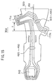
- FIG.1 is a perspective view of a magnetic head slider supporting device 20 according to the first embodiment of the present invention.
- FIGS.2A to 2D are enlarged views of parts of the magnetic head slider supporting device 20 shown in FIG.1.
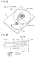
- FIG.3A is a perspective view of a magnetic disc apparatus 21 having the magnetic head slider supporting device 20 shown in FIG.1.
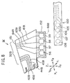
- FIG.3B is an enlarged view of a part of the magnetic disc apparatus 21 shown in FIG.3A.
- the magnetic disc apparatus 21 comprises two rotatable magnetic discs 23-1 and 23-2, an electromagnetically driven actuator 24 having a coil and a permanent magnet, arms 25-1, 25-2 and 25-3 rotated by the actuator 24 and magnetic head slider supporting devices 20-1, 20-2, 20-3 and 20-4 which are mounted to the corresponding arms 25-1 to 25-3. These parts are accommodated in a housing 22.
- the magnetic discs 23-1 and 23-2 are rotated and the actuator 24 is driven so that the arms 25-1, 25-2 and 25-3 are rotated.
- the magnetic head slider supporting devices 20-1 to 20-4 are moved together with the arms 25-1 to 25-3 so that access is provided to predetermined tracks of the magnetic discs 23-1 and 23-2 so as to perform an information recording and reproducing operation.
- a distance between the magnetic discs 23-1 and 23-2 is as small as 2 mm.
- Each of the magnetic head slider supporting devices 20-1 to 20-4 have the same structure, and reference numeral 20 is used for indicating one of the magnetic head slider supporting devices 20-1 to 20-4.
- the magnetic head slider supporting device 20 comprises, as shown in FIG.1, a load beam (hereinafter referred to as suspension) 30, an interconnecting member (spacer) 70, a magnetic head slider 80, a bare head IC chip 90 and a flexible printed wiring board 100.
- suspension a load beam
- spacer interconnecting member
- the suspension 30 is made of a stainless steel plate having a thickness of 25 ⁇ m.
- the suspension 30 includes a magnetic head slider supporting section 31 having a gimbal structure at a free end (X1 side) and a mount section 32 which is mounted to the interconnecting member 70 on a base end (X2 side). Additionally, the suspension 30 includes a rigid section 33 and an elastically bendable section 34 between the magnetic head slider supporting section 31 and the mount section 32.
- the rigid section 33 extends from the magnetic head slider supporting section 31, and has a high rigidity, that is, it is not bendable.
- the elastically bendable section 34 can be elastically bent, and extends between the rigid section 33 and the mount section 32.
- the mount section 32 has a tongue portion 35 on one side thereof along a longitudinal direction.
- a width "a" of the tongue portion 35 which extends from the mount section 32 is about 1 mm. The width "a” is determined by a size of the bare head IC chip 90.
- a plurality of openings 36, 37 and 38 are formed in the suspension 30.
- a plurality of slits 39 and 40 are also formed in the suspension 30.
- the slits 39 and 40 are formed in the elastically bendable section 34, and extend in the longitudinal direction of the suspension 30 so as to facilitate elastic bending of the elastically bendable section 34.
- the rigidity of the rigid section 33 is provided by rib portions 41 (only one shown in the figure) formed on opposite sides of the suspension 30. The rib portions 41 are formed by bending.
- a length L between the magnetic head slider supporting section 31 and an end of the elastically bendable section 34 connected to the mount section 32 is as short as 7 mm.
- Each copper wiring patterns 42, 43, 44 and 45 for signal transmission are formed on a top surface 30a of the suspension 30 so as to extend from the magnetic head slider supporting section 31 to the mount section 32 through the rigid section 33 and the elastically bendable section 34.
- ends of the wiring patterns 42, 43, 44 and 45 are provided with fine pads 46, 47, 48 and 49, respectively, and are located on the tongue portion 35.
- the wiring patterns 42, 43, 44 and 45 are formed on a polyimide base layer 50 provided on the top surface 30a of the suspension 30, and are protected by a cover layer 51 made of polyimide. Since the above-mentioned distance L is as short as 7 mm, a length of each of the wiring patterns 42, 43, 44 and 45 is also short. Thus, an inductance of each of the wiring patterns 42, 43, 44 and 45 is small, and a capacitance provided by a pair of adjacent wiring patterns 42, 43, 44 and 45 is also small.
- a plurality of fine pads 52, 53, 54 and 55, a plurality of pads 56, 57, 58 and 59 and a plurality of wiring patterns 61, 62, 63 and 64 for signal transmission are also formed on the tongue portion 35.
- the fine pads 46, 47, 48 and 49 and the fine pads 52, 53, 54 and 55 are arranged on the X1 side of the tongue portion 35.
- the pads 56, 57, 58 and 59 are arranged in a direction indicated by arrows X1 and X2.
- Each of the pads 56, 57, 58 and 59 is a few times larger than each of the fine pads 52, 53, 54 and 55.
- the wiring patterns 61, 62, 63 and 64 connect the fine pads 52, 53, 54 and 55 to the pads 56, 57, 58 and 59, respectively. Similar to the wiring patterns 42, 43, 44 and 45, the wiring patterns 61, 62, 63 and 64 are formed on a polyimide base layer, and are protected by a cover layer made of polyimide.
- a bare head IC chip mounting portion 65 is formed by a portion including the fine pads 46, 47, 48 and 49 and the fine pads 52, 53, 54 and 55.
- a flexible printed board connecting portion 66 is formed by a portion including the pads 56, 57, 58 and 59.
- the interconnecting member 70 is made of a stainless steel plate having a thickness of 0.20 mm.
- the interconnecting layer 70 includes a suspension mount section 71 on an end (X1 side) and a mount section 72 on a base end (X2 side) which is fixed to the arm 25.
- the suspension mount section 71 includes a protruding portion 73.
- the mount section 72 includes an opening 74 for caulking.
- the interconnecting member 70 serves to fix the suspension 30 to the arm 25, that is, the interconnecting member 70 functions to mount the magnetic head slider supporting device 20 to the arm 25.
- the magnetic head slider 80 As shown in FIG.1, the magnetic head slider 80 is referred to as a picoslider.
- the magnetic head slider 80 includes a head 82, wiring patterns (not shown in the figure) and electrodes 83 provided on an end of each of the wiring patterns.
- the head 82 is formed by a thin-film forming method by utilizing an inductance head for recording and a magnetoresistance element or a macro magnetoresistance element for reproduction.
- the bare head IC chip 90 has an integrated circuit 92 formed on a bottom surface 91 thereof.
- the integrated circuit 92 is covered by a protective film 93.
- a plurality of fine bumps are formed on the bottom surface 91.
- the arrangement of the fine bumps 84 matches the arrangement of the fine pads 46 to 49 and 52 to 55.
- the integrated circuit 92 has a circuit for amplifying a signal reproduced by the head 82.
- a dimension "b" of one side of the bare head IC chip 90 is slightly less than 1 mm which is much smaller than a dimension (5 mm) of one side of a conventional head IC which is sealed by a synthetic resin.
- a thickness "c" of the bare head IC chip 90 is 0.3 mm which is much smaller than a thickness (2 mm) of the conventional IC head which is sealed by a synthetic resin.
- a weight of the bare head IC chip 90 is 0.5 mg which is much lighter than a weight (10 mg) of the conventional head IC which is sealed by a synthetic resin.
- the flexible printed board 100 is a belt member having a width "e" of about 1 mm.
- the flexible printed board 100 has four wiring patterns 101, 102, 103 and 104 which extend in the direction X1-X2.
- Four pads 105, 106, 107 and 108 are provided on ends of the wiring patterns 101, 102, 103 and 104.
- the flexible printed board 100 also has four pads 109, 110, 111 and 112 on an end opposite to the end where the pads 105 to 108 are formed.
- the pads 105 to 108 are arranged along a line, and the pads 105 to 108 and the pads 56, 57, 58 and 59 are arranged in the same relationship.
- the suspension 30 is positioned by the opening 38 being fit on the protruding portion 73, and the mount section 32 is placed on and fixed to a suspension mount portion 71 of the interconnecting part 70.
- the tongue portion 35 is located on a side of the interconnecting member 70.
- the elastically bendable section 34 extends from the interconnecting member 70.
- the magnetic head slider 80 is secured to the magnetic head slider mounting section 31 by adhesive, and the electrodes 83 are connected to the corresponding pads 67 provided on ends of the wiring patterns 42, 43, 44 and 45 by gold (Au) balls 84 attached by a heat press method.
- the bare head IC chip 90 is a face-down flip chip type.
- the fine bumps 94 are connected to the fine pads 46-49 and 52-55.
- the bare head IC chip 90 is mounted on the bare head IC chip mounting portion 65 by a heat pressing method, an ultrasonic method or an adhesive. Additionally, the flexible printed board 100 connects the pads 105 to 108 to the pads 56 to 59 so as to be connected to the flexible printed board mounting portion 66, and extends in a direction X2.
- the width "a" of the tongue portion 35 can be as small as about 1 mm, and a dimension "f” of extension of the tongue portion 35 downwardly from a bottom surface of the interconnecting member 70 is as short as 0.8 mm.
- the above-mentioned magnetic head slider supporting device 20 is fixed to an end of the arm 25 by utilizing the opening 74 for caulking in the mount portion 72 of the interconnecting member 70.
- the magnetic head slider supporting device 20 extends in a direction of the axis of the arm 25.
- the pads 109 to 112 on the opposite end of the flexible printed board 100 are connected to a circuit board (not shown in the figures) of the magnetic disc apparatus 21, and sequentially connected a main IC 120 mounted on the circuit board.
- the main IC 120 has a recording and reproducing circuit and an amplifying circuit, and is sealed by a synthetic resin.
- FIG.3B Other magnetic head slider supporting devices shown in FIG.3B have the same construction as the above-mentioned magnetic head slider supporting device 20. Thus, a flexible printed board of other magnetic head slider supporting devices is connected to the main IC 120.
- the above-mentioned magnetic head slider supporting device 20 (the magnetic disc apparatus 21) has the following features.
- the magnetic head slider supporting device 20 is assembled in a procedure in which the head 82 of the magnetic head slider 80 is not statically destroyed.
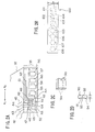
- FIG.4 is a flowchart of an assembly operation of the magnetic head slider supporting device 20.
- the suspension 30 is mounted to the interconnecting member 70 (step 130).
- the bare head IC chip 90 is mounted before the magnetic head slider 80 is mounted (step 130).
- the flexible printed board 100 is connected (step 132).
- the magnetic head slider 80 is mounted (step 130).
- the magnetic head slider supporting device 20 is completed. Since the bare head IC chip 90 has already been mounted, the head 82 is prevented from being statically destroyed during an operation for mounting the magnetic head slider 80 or handling after the magnetic head slider 80 is mounted.
- step 134 a floating test is performed for the magnetic head slider 80 (step 134). Since the bare head IC chip 90 is mounted, the head 82 is prevented from being statically destroyed during the floating test of the magnetic head slider 80. Then, the magnetic head slider supporting device 20 is mounted to the arm 25 (step 135).
- FIG.5 is a flowchart of another assembly operation of the magnetic head slider supporting device 20. This assembling operation uses a dummy circuit chip.
- the dummy chip circuit has the same size as that of the bare head IC chip 90.
- the dummy chip circuit has the same number fine bumps provided in the same arrangement as the fine bumps 94 of the bare head IC chip 90. Additionally, the dummy circuit chip has a short circuit which interconnects the corresponding fine bumps by wiring patterns. When the dummy circuit chip is mounted to the bare head IC chip mounting portion 65, the fine pads 46 to 49 and the corresponding fine bumps 52 to 55 are short circuited.
- steps that are the same as the steps shown in FIG.4 are given the same step numbers.
- the dummy circuit chip is mounted to the bare head IC chip mounting portion 65 (step 140). Thereafter, steps 132, 133 and 143 are performed. Since dummy circuit chip is mounted on the base head IC chip mounting portion 65 and the fine pads 46 to 49 and the corresponding fine pads 52 to 55 are short circuited, the head 82 is protected from being statically destroyed during an operation for mounting the magnetic head slider 80 or for handling after the magnetic head slider 80 is mounted or floating test of the magnetic head slider 80.
- step 134 the dummy circuit chip 90 is removed (step 141). Then the bare head IC chip 90 is mounted (step 142). Thereafter, process 135 is performed.
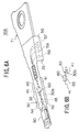
- FIGS.6A and 6B A description will now be given, with reference to FIGS.6A and 6B, of a magnetic head slider supporting device 20A according to a second embodiment of the present invention.
- the magnetic head slider supporting device 20A has the same structure as the magnetic head slider supporting device 20 shown in FIG.1 except for the position where the bare head IC chip 90 is mounted.
- FIGS.6A and 6B parts that are the same as the parts shown in FIG.1 are given the same reference numerals.
- the four wiring patterns 42, 43, 44 and 45 are formed on a bottom surface 30b which is a side where the rib 41 is uprightly bent.
- the bare head IC chip mounting portion 65 is formed on the bottom surface 30b within the rigid section 33.
- the bare head IC chip 90 is mounted on the thus formed bare head IC chip mounting portion 65.
- FIG.6B since the bare head IC chip 90 is accommodated within a height "h" of the rib 41, there is no interference with an adjacent magnetic head slider supporting device.
- a length of a wiring pattern from the head to the bare head IC chip 90 is less than that of the magnetic head slider supporting device 20 shown in FIG.1.
- the magnetic disc apparatus 21A using the magnetic head slider supporting device 20A can increase a signal writing frequency more than the magnetic disc apparatus 21 having the magnetic head slider supporting apparatus 20.
- the magnetic disc apparatus 21A using the magnetic head slider supporting device 20A can write and read a signal having a frequency of 200 to 300 MHz.
- the following third, fourth and fifth embodiments are directed to a structure in which the tongue portion is provided on each side of the interconnecting member of the suspension, that is, two tongue portions are provided to the interconnecting member so that bare head IC chip is mounted to one of the tongue portions and an end of the flexible printed board 100 is connected by soldering to the other one of the tongue portions.
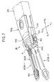
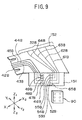
- FIGS.7 to 10 show a magnetic head slider supporting device 20B according to the third embodiment of the present invention.
- parts that are the same as the parts shown in FIGS.1 and 2 are given the same reference numerals, and parts that correspond to the parts shown in FIGS.1 and 2 are given the same reference numerals with a suffix "B".
- the magnetic head slider supporting device 20B-1 has a suspension 30B.
- a mount section 32B of the suspension 30B which is mounted to an interconnecting member 70B has a first tongue portion 151 and a second tongue portion 152.
- the mount section 32B of the suspension 30B has a side portion 151a on a Y2 side and a side portion 152a on a Y1 side, a direction Y1-Y2 being perpendicular to a longitudinal center line 153 of the suspension 30B.
- the first tongue portion 151 is formed by bending the side portion 151a of the mount section 32B on the Y2 side by 90 degrees in a downward direction (in a direction indicated by an arrow Z).
- the second tongue portion 152 is formed by bending the side portion 152a of the mount section 32B on the Y1 side by 90 degrees in a downward direction (in the direction indicated by the arrow Z).
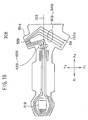
- fine pads 46B, 47B, 48B and 49B and fine pads 52B, 53B, 54B and 55B are formed on the first tongue portion 151.
- pads 56B, 57B, 58B and 59B are formed on the second tongue portion 152.
- first wiring patterns 42B, 43B, 44B and 45B for signal transmission extend from a magnetic head slider mounting section 31B to the first tongue portion 151 through a rigid section 33B, an elastically bending section 34B and the mount section 32B. Ends of the first wiring patterns 42B, 43B, 44B and 45B are provided with fine pads 46B, 47B, 48B and 49B, respectively.
- second wiring patterns 61B, 62B, 63B and 64B for signal transmission extend from the fine pads 52B, 53B, 54B and 55B, traverse the mount section 32B in the Y1 direction and reach the pads 59B, 58B, 57B and 56B, respectively.
- a portion encircled by a double dashed chain line which includes the fine pads 46B, 47B, 48B and 49B and the fine pads 52B, 53B, 54B and 55B, constitutes a bare head IC chip mounting portion 65B.
- a portion encircled by a double dashed chain line which includes the pads 56B, 57B, 58B and 59B, constitutes a flexible printed board connecting portion 66B.
- the magnetic head slider 80 is mounted on an end of the suspension 30B.
- the mount section 32B is fixed to the interconnecting member 70B by welding.
- a point 155 indicates a welded position.
- the bare head IC chip 90 is mounted on the bare head IC chip mounting portion 65B, and an end of the flexible printed board 100 is soldered to the flexible printed board connecting portion 66B.
- the magnetic head slider supporting device 20B-2 has the same structure as the above-mentioned magnetic head slider supporting device 20B-1.
- the interconnecting member 70B of the magnetic head slider supporting device 20B-1 is mounted to an upper side of the arm 25. Additionally, the interconnecting member 70B of the magnetic head slider supporting device 20B-2 is mounted upside down to a lower side of the arm 25.
- the magnetic head slider supporting devices 20B-1 and 20B-2 are interposed between the magnetic discs 23-1 and 23-2 (refer to FIG.3B). In this arrangement, the magnetic head slider supporting devices 20B-1 and 20B-2 are in a back-to-back relationship.
- the bare head IC chip mounting portion of one of the magnetic head slider supporting devices 20B-1 and 20B-2 and the flexible printed board connecting portion of the other one of the magnetic head slider supporting devices 20B-1 and 20B-2 are positioned on the same side.
- the bare head IC chip mounting portion 65B and the flexible printed board connecting portion 66B are formed on the separate tongue portions 151 and 152, respectively, the bare head IC chip 90 does not interfere with an operation for soldering the flexible printed board 100 to the flexible printed board connecting portion 66B.
- the operation for soldering the flexible printed board 100 to the flexible printed board connecting portion 66B can be performed smoothly.
- the flexible printed circuit board 100 does not interfere with an operation for mounting the bare head IC chip 90.
- the operation for mounting the flexible printed circuit board 100 to the flexible printed board connecting portion 66B can be performed smoothly.
- the magnetic disc apparatus 20B can write and read a signal having a frequency exceeding 70 MHz and up to 200 MHz since the above-mentioned magnetic head slider supporting devices 20B-1 and 20B-2 are incorporated therein.
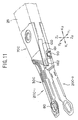
- FIG.11 shows magnetic head slider supporting devices 20C-1 and 20C-2 according to a fourth embodiment of the present invention.
- parts that are the same as the parts shown in FIGS.1 and 2 are given the same reference numerals, and parts that correspond to the parts shown in FIGS.1 and 2 are given the same reference numerals with a suffix "C".
- the magnetic head slider supporting device 20C-1 has a suspension 30C.
- the suspension 30C has the same structure as the suspension 30B shown in FIG.10 except for a first tongue portion 161 (161a) and a second tongue portion 162 (162a) being offset from each other in the longitudinal center axis 153 by a distance "i".
- the distance "i" corresponds to a length "j" of the first tongue portion 161 (161a).
- An end 161b of the first tongue portion 161a and an end 162b of the second tongue portion 162a are located substantially in the same position with respect to the X1-X2 direction.
- a bear head IC chip mounting portion 65C is formed in the first tongue portion 161 (161a).
- a flexible printed board connecting portion 66C is formed in the second tongue portion 162 (162a).
- First wiring patterns 42C, 43C, 44C and 45C extend from a magnetic head slider mounting section 31C to the bare head IC chip mounting portion 65C.
- Second wiring patterns 61C, 62C, 63C and 64C traverse the mount section 32C and extend to the flexible printed board connecting portion 66C.
- the magnetic head slider 80 is mounted on an end of the suspension 30C.
- the mount section 32C is fixed to the interconnecting member 70C by welding.
- the bare head IC chip 90 is mounted on the bare head IC chip mounting portion 65B (refer to the magnetic head slider supporting device 20C-2), and an end of the flexible printed board 100 is soldered to the flexible printed board connecting portion 66C.
- the magnetic head slider supporting device 20C-2 has the same structure as the above-mentioned magnetic head slider supporting device 20C-1.
- the interconnecting member 70C of the magnetic head slider supporting device 20C-1 is mounted to an upper side of the arm 25. Additionally, the interconnecting member 70C of the magnetic head slider supporting device 20C-2 is mounted upside down to a lower side of the arm 25. The magnetic head slider supporting devices 20C-1 and 20C-2 are interposed between the magnetic discs 23-1 and 23-2 (refer to FIG.3B).
- the magnetic head slider supporting devices 20C-1 and 20C-2 are in a back-to-back relationship.
- the bare head IC chip mounting portion of one of the magnetic head slider supporting devices 20C-1 and 20C-2 and the flexible printed board connecting portion of the other one of the magnetic head slider supporting devices 20C-1 and 20C-2 are positioned on the same side.
- the bare head IC chip mounting portion 65C of the first tongue portion 161 and the flexible printed board connecting portion 66C of the second tongue portion 162 are formed on the same side.
- the first tongue portion 161 and the second tongue portion 162 are arranged in an offset relationship from each other in the X1-X2 direction.
- the jig can be inserted without interference of the mounted bare head IC chip 90.
- the operation for soldering the flexible printed board 100 to the flexible printed board connecting portion 66C can be performed smoothly.
- the magnetic disc apparatus 20C can write and read a signal having a frequency exceeding 70 MHz and up to 200 MHz since the above-mentioned magnetic head slider supporting devices 20C-1 and 20C-2 are incorporated therein.
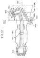
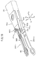
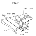
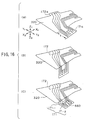
- FIGS.13 and 14 show magnetic head slider supporting devices 20D-1 and 20D-2 according to a fifth embodiment of the present invention.
- parts that are the same as the parts shown in FIGS.1 and 2 are given the same reference numerals, and parts that correspond to the parts shown in FIGS.1 and 2 are given the same reference numerals with a suffix "D".
- the magnetic head slider supporting device 20C-1 has a suspension 30D.
- the suspension 30D has the same structure as the suspension 30C shown in FIGS.11 and 12 except for a first tongue portion 171 (171a) being bent in two steps.
- the suspension 30D has the same structure as the suspension 30B shown in FIGS.7 to 10 except for the first tongue portion 171 (171a) and a second tongue portion 172 (172a) being offset from each other in the longitudinal center axis 153 by a distance "i" and the first tongue portion 171 (171a) is bent in two steps.
- the first tongue portion 171a since the first tongue portion 171 is formed by bending in two steps, the first tongue portion 171a has a dimension "k" which is greater than the dimension "1" of the first tongue portion 161a shown in FIG.12.
- the first tongue portion 171a is bent downwardly, in a first step, by 90 degrees with respect to the mount section 32D as shown in FIG.16-(B).
- an end portion of the first tongue portion 171a is bent 90 degrees in a reverse direction so that the first tongue portion 171 is formed as shown in FIG.16-(C).
- the first tongue portion 171 comprises a vertical wall portion 171-1 which extends a distance corresponding to a thickness of the interconnecting member 70D and a table portion 171-2 which extends parallel to the mount section 32D from a position lower than an upper surface of the mount section 32D by the thickness of the interconnecting member 70D.
- a bare head IC chip mounting portion 65D is formed in the table portion 171-2.
- the second tongue portion 172a is bent 90 degrees so that the second tongue portion 172 is formed as show in FIG.13.
- the flexible printed board connecting portion 66D is formed in the second tongue portion 172.
- First wiring patterns 42D, 43D, 44D and 45D extend from a magnetic head slider mounting section 31D to the bare head IC chip mounting portion 65D.
- Second wiring patterns 61D, 62D, 63D and 64D traverse the mount section 32D and extend to the flexible printed board connecting portion 66D.
- the magnetic head slider 80 is mounted on an end of the suspension 30D.
- the mount section 32D is fixed to the interconnecting member 70D by welding.
- the bare head IC chip 90 is mounted on the bare head IC chip mounting portion 65D, and an end of the flexible printed board 100 is soldered to the flexible printed board connecting portion 66D.
- the bare head IC chip 90D is mounted on the table portion 171-2 which extends in a horizontal direction, the IC chip 90 is accommodated within a predetermined thickness without being influenced by a dimension "m" of the IC chip 90 even if the dimension "m" is large.
- the magnetic head slider supporting device 20D-2 has the same structure as the above-mentioned magnetic head slider supporting device 20D-1.
- the interconnecting member 70D of the magnetic head slider supporting device 20D-1 is mounted to an upper side of the arm 25. Additionally, the interconnecting member 70D of the magnetic head slider supporting device 20D-2 is mounted upside down to a lower side of the arm 25.
- the magnetic head slider supporting devices 20D-1 and 20D-2 are interposed between the magnetic discs 23-1 and 23-2 (refer to FIG.3B). Even if the a size of the bare head IC chip 90 is large, sufficient room is provided between the mounted bare head IC chip 90 and each of the magnetic discs 23-1 and 23-2.
- first tongue portion 171 and the second tongue portion 172 may be arranged in the same position with respect to the longitudinal direction of the suspension 30D.
- the magnetic disc apparatus 20D can write and read a signal having a frequency exceeding 70 MHz and up to 200 MHz since the above-mentioned magnetic head slider supporting devices 20D-1 and 20D-2 are incorporated therein.
- the base side of the suspension 30 may be directly fixed to the arm 25.
- a head slider having an optical head can be applied to the above mentioned embodiments instead of the magnetic head slider 80.
Landscapes
- Supporting Of Heads In Record-Carrier Devices (AREA)
- Adjustment Of The Magnetic Head Position Track Following On Tapes (AREA)
- Moving Of Heads (AREA)
Applications Claiming Priority (5)
| Application Number | Priority Date | Filing Date | Title |
|---|---|---|---|
| JP24549597 | 1997-09-10 | ||
| JP24549597 | 1997-09-10 | ||
| JP00259398A JP3634134B2 (ja) | 1997-09-10 | 1998-01-08 | サスペンション、ヘッドスライダ支持装置、及びディスク装置 |
| JP259398 | 1998-01-08 | ||
| EP98302347A EP0902427B1 (de) | 1997-09-10 | 1998-03-27 | Stützaufhängung für Plattengerät-Kopfgleiter |
Related Parent Applications (1)
| Application Number | Title | Priority Date | Filing Date |
|---|---|---|---|
| EP98302347A Division EP0902427B1 (de) | 1997-09-10 | 1998-03-27 | Stützaufhängung für Plattengerät-Kopfgleiter |
Publications (2)
| Publication Number | Publication Date |
|---|---|
| EP1501078A2 true EP1501078A2 (de) | 2005-01-26 |
| EP1501078A3 EP1501078A3 (de) | 2008-08-20 |
Family
ID=26336011
Family Applications (4)
| Application Number | Title | Priority Date | Filing Date |
|---|---|---|---|
| EP04024375A Withdrawn EP1505574A3 (de) | 1997-09-10 | 1998-03-27 | Stützaufhängung für Plattengerät-Kopfgleiter |
| EP04024374A Withdrawn EP1501078A3 (de) | 1997-09-10 | 1998-03-27 | Verfaren zur Herstellung einer magnetischen Kopfgleiteraufhängung |
| EP04009806A Withdrawn EP1467368A1 (de) | 1997-09-10 | 1998-03-27 | Stützaufhängung für Plattengerät-Kopfgleiter |
| EP98302347A Expired - Lifetime EP0902427B1 (de) | 1997-09-10 | 1998-03-27 | Stützaufhängung für Plattengerät-Kopfgleiter |
Family Applications Before (1)
| Application Number | Title | Priority Date | Filing Date |
|---|---|---|---|
| EP04024375A Withdrawn EP1505574A3 (de) | 1997-09-10 | 1998-03-27 | Stützaufhängung für Plattengerät-Kopfgleiter |
Family Applications After (2)
| Application Number | Title | Priority Date | Filing Date |
|---|---|---|---|
| EP04009806A Withdrawn EP1467368A1 (de) | 1997-09-10 | 1998-03-27 | Stützaufhängung für Plattengerät-Kopfgleiter |
| EP98302347A Expired - Lifetime EP0902427B1 (de) | 1997-09-10 | 1998-03-27 | Stützaufhängung für Plattengerät-Kopfgleiter |
Country Status (6)
| Country | Link |
|---|---|
| US (2) | US6134084A (de) |
| EP (4) | EP1505574A3 (de) |
| JP (1) | JP3634134B2 (de) |
| KR (1) | KR100310071B1 (de) |
| CN (2) | CN1115692C (de) |
| DE (1) | DE69830693T2 (de) |
Families Citing this family (39)
| Publication number | Priority date | Publication date | Assignee | Title |
|---|---|---|---|---|
| US6437944B2 (en) * | 1997-10-20 | 2002-08-20 | Fujitsu Limited | Head slider supporting device, disk device and suspension |
| EP0911812B1 (de) * | 1997-10-20 | 2003-05-21 | Fujitsu Limited | Träger für Kopfgleitkörper, Plattengerät und Aufhängung |
| US6278583B1 (en) * | 1997-10-31 | 2001-08-21 | Questek Innovations, Inc. | Low impedance head/preamplifier chip position in a disk drive |
| JP3992821B2 (ja) * | 1998-03-20 | 2007-10-17 | 富士通株式会社 | ヘッドスライダ支持装置、ディスク装置及びサスペンション |
| JP3799168B2 (ja) * | 1998-08-20 | 2006-07-19 | 株式会社日立グローバルストレージテクノロジーズ | 磁気記録再生装置 |
| US6252743B1 (en) * | 1998-11-02 | 2001-06-26 | Read-Rite Corporation | Read/write positioning arm with interspaced amplifier chips |
| WO2000030081A1 (en) * | 1998-11-13 | 2000-05-25 | Tdk Corporation | Record/reproduce head support mechanism and record/reproduce apparatus |
| JP2000339648A (ja) * | 1999-05-24 | 2000-12-08 | Tdk Corp | 磁気ヘッド装置の製造方法 |
| JP2001035107A (ja) * | 1999-07-15 | 2001-02-09 | Fujitsu Ltd | ヘッドサスペンションおよびヘッドアセンブリの組立方法、並びにディスク装置 |
| JP3678613B2 (ja) * | 1999-07-30 | 2005-08-03 | 富士通株式会社 | ヘッドの微小移動機構 |
| US6483669B1 (en) | 1999-09-17 | 2002-11-19 | Hutchinson Technology Incorporated | Integrated lead suspension with IC chip and method of manufacture |
| JP2001176225A (ja) | 1999-12-15 | 2001-06-29 | Tdk Corp | ヘッドサスペンションアセンブリ |
| JP2001184618A (ja) * | 1999-12-24 | 2001-07-06 | Hitachi Ltd | 磁気ディスク装置 |
| JP2001266511A (ja) * | 2000-03-24 | 2001-09-28 | Toshiba Corp | ヘッドサスペンションアッセンブリ、およびヘッドサスペンションアッセンブリを備えた磁気ディスク装置 |
| JP2001312809A (ja) * | 2000-04-27 | 2001-11-09 | Fujitsu Ltd | デイスク装置のヘッドサスペンション、デイスク装置及びヘッドicの検査方法 |
| JP2002056515A (ja) * | 2000-08-09 | 2002-02-22 | Tdk Corp | 磁気ヘッド装置及び該磁気ヘッド装置を備えた磁気ディスク装置 |
| JP2002251707A (ja) * | 2000-12-18 | 2002-09-06 | Hitachi Ltd | 磁気ディスク装置 |
| KR20030066717A (ko) * | 2000-12-20 | 2003-08-09 | 후지쯔 가부시끼가이샤 | 서스펜션 및 디스크 장치 |
| US6522504B1 (en) * | 2001-01-31 | 2003-02-18 | Western Digital Technologies, Inc. | Head stack assembly and disk drive using a reversed direction head gimbal assembly |
| JP4277455B2 (ja) * | 2001-02-27 | 2009-06-10 | Tdk株式会社 | ヘッドジンバルアセンブリ |
| JP3883037B2 (ja) * | 2001-02-28 | 2007-02-21 | 株式会社日立製作所 | 媒体記録再生システム |
| US6704165B2 (en) * | 2001-06-08 | 2004-03-09 | Seagate Technology Llc | Attachment of a head-gimbal assembly to a printed circuit board actuator arm using Z-axis conductive adhesive film |
| JP4058414B2 (ja) * | 2002-01-09 | 2008-03-12 | 富士通株式会社 | ディスク装置のキャリッジアーム組立体 |
| KR20040067417A (ko) * | 2003-01-23 | 2004-07-30 | 삼성전자주식회사 | 광픽업 액츄에이터 |
| WO2004100136A1 (en) * | 2003-05-12 | 2004-11-18 | Sae Magnetics (U. K.) Ltd. | An improved electrical connection between a suspension flexure cable and a head stack assembly flexible circuit |
| JP2005108357A (ja) * | 2003-09-30 | 2005-04-21 | Toshiba Corp | ヘッドアクチュエータアッセンブリおよびこれを備えたディスク装置 |
| JP2006040414A (ja) * | 2004-07-27 | 2006-02-09 | Nitto Denko Corp | 配線回路基板 |
| CN1728265B (zh) * | 2004-07-29 | 2010-04-21 | 新科实业有限公司 | 磁头悬臂组合及其制造方法、以及使用该磁头悬臂组合的磁盘驱动器 |
| JP4187757B2 (ja) * | 2006-06-22 | 2008-11-26 | 日東電工株式会社 | 配線回路基板 |
| EP2073201A1 (de) * | 2007-12-21 | 2009-06-24 | Deutsche Thomson OHG | Schwingarm-Aktuator für eine Abtasteinrichtung |
| US8174796B2 (en) * | 2008-03-21 | 2012-05-08 | Seagate Technology, Llc | Baseplate interconnect |
| JP5142951B2 (ja) * | 2008-11-10 | 2013-02-13 | 日東電工株式会社 | 配線回路基板およびその製造方法 |
| US8400891B2 (en) * | 2009-06-26 | 2013-03-19 | Seagate Technology Llc | Delay line on a movable substrate accessing data storage media |
| JP5478331B2 (ja) * | 2010-03-31 | 2014-04-23 | 日本発條株式会社 | 電子機器と、ディスク装置用サスペンション |
| US9437227B1 (en) * | 2015-09-30 | 2016-09-06 | Sae Magnetic (H.K.) Ltd. | Thermally assisted magnetic recording head slider, method of manufacturing the same, head gimbal assembly, and hard disk drive |
| US9659590B1 (en) * | 2015-10-30 | 2017-05-23 | Seagate Technology Llc | Angled near-field transducer and waveguide |
| US9659591B1 (en) | 2016-01-14 | 2017-05-23 | Seagate Technology Llc | Polynomial spiral waveguide that facilitates coupling light to a near-field transducer at an oblique angle |
| JP2021048272A (ja) * | 2019-09-19 | 2021-03-25 | 株式会社東芝 | ディスク装置 |
| JP2021144779A (ja) * | 2020-03-13 | 2021-09-24 | 株式会社東芝 | サスペンションアッセンブリおよびディスク装置 |
Family Cites Families (23)
| Publication number | Priority date | Publication date | Assignee | Title |
|---|---|---|---|---|
| JPS63292412A (ja) * | 1987-05-25 | 1988-11-29 | Hitachi Ltd | 磁気ディスク装置 |
| JPH0823973B2 (ja) * | 1987-07-10 | 1996-03-06 | 株式会社日立製作所 | 磁気ディスク装置のサ−ボヘッドア−ム構造 |
| US5006946A (en) * | 1989-04-19 | 1991-04-09 | Tdk Corporation | Flexible polymeric resinous magnetic head supporting device |
| JPH0325717A (ja) * | 1989-06-23 | 1991-02-04 | Mitsubishi Electric Corp | 磁気ヘッド装置 |
| JPH0670848B2 (ja) * | 1989-09-21 | 1994-09-07 | 三菱電機株式会社 | 磁気ヘッド装置 |
| JP2777454B2 (ja) * | 1990-03-20 | 1998-07-16 | 富士通株式会社 | 磁気ヘッドアセンブリ及びその製造方法 |
| US5055969A (en) * | 1990-09-28 | 1991-10-08 | Seagate Technology, Inc. | Servo/data actuator arm flexible circuit |
| JP3108120B2 (ja) | 1991-03-26 | 2000-11-13 | 光計測技術開発株式会社 | InGaAsP四元混晶のエッチング方法 |
| JP3272015B2 (ja) | 1992-02-07 | 2002-04-08 | 株式会社日本触媒 | 排気ガス浄化用触媒 |
| GB2256740A (en) * | 1991-06-14 | 1992-12-16 | Marconi Electronic Devices | Magnetic head support carrying electronic circuits |
| JPH05143949A (ja) * | 1991-11-20 | 1993-06-11 | Hitachi Ltd | 磁気ヘツド |
| JPH05282642A (ja) * | 1992-04-02 | 1993-10-29 | Sony Corp | 磁気ディスク装置 |
| CA2090708A1 (en) * | 1992-04-30 | 1993-10-31 | Jeffrey Merritt Mckay | Combination transducer/slider/suspension and method for making |
| JPH0652531A (ja) * | 1992-07-30 | 1994-02-25 | Nec Ibaraki Ltd | 磁気ヘッド位置決め機構 |
| JP3262445B2 (ja) * | 1994-02-18 | 2002-03-04 | 富士通株式会社 | ヘッドアセンブリ及び記憶装置 |
| US6014289A (en) * | 1994-03-22 | 2000-01-11 | Hutchinson Technology Incorporated | Integrated circuit on a monocoque suspension |
| US5995325A (en) * | 1994-04-20 | 1999-11-30 | Seagate Technology, Inc. | Transducer signal wire termination |
| US5491605A (en) * | 1994-12-23 | 1996-02-13 | International Business Machines Corporation | Shorted magnetoresistive head elements for electrical overstress and electrostatic discharge protection |
| US5608591A (en) * | 1995-06-09 | 1997-03-04 | International Business Machines Corporation | Integrated head-electronics interconnection suspension for a data recording disk drive |
| JP2894262B2 (ja) * | 1995-10-27 | 1999-05-24 | ティーディーケイ株式会社 | サスペンション装置、スライダ−サスペンションアセンブリ及びアセンブリキャリッジ装置 |
| JP2947147B2 (ja) * | 1995-10-27 | 1999-09-13 | ティーディーケイ株式会社 | サスペンション装置及びその製造方法 |
| JPH09223304A (ja) * | 1996-02-15 | 1997-08-26 | Tdk Corp | 磁気ヘッド装置 |
| JP3130860B2 (ja) * | 1997-03-04 | 2001-01-31 | ティーディーケイ株式会社 | 磁気ヘッド装置及び該磁気ヘッド装置を備えた磁気ディスク装置 |
-
1998
- 1998-01-08 JP JP00259398A patent/JP3634134B2/ja not_active Expired - Fee Related
- 1998-03-24 US US09/046,827 patent/US6134084A/en not_active Expired - Fee Related
- 1998-03-27 EP EP04024375A patent/EP1505574A3/de not_active Withdrawn
- 1998-03-27 EP EP04024374A patent/EP1501078A3/de not_active Withdrawn
- 1998-03-27 EP EP04009806A patent/EP1467368A1/de not_active Withdrawn
- 1998-03-27 EP EP98302347A patent/EP0902427B1/de not_active Expired - Lifetime
- 1998-03-27 DE DE69830693T patent/DE69830693T2/de not_active Expired - Fee Related
- 1998-04-08 KR KR1019980012373A patent/KR100310071B1/ko not_active Expired - Fee Related
- 1998-04-09 CN CN98106369A patent/CN1115692C/zh not_active Expired - Fee Related
-
2000
- 2000-08-22 US US09/643,536 patent/US6388840B1/en not_active Expired - Fee Related
-
2002
- 2002-11-18 CN CNB021513503A patent/CN1204545C/zh not_active Expired - Fee Related
Also Published As
| Publication number | Publication date |
|---|---|
| EP1505574A3 (de) | 2008-08-27 |
| DE69830693T2 (de) | 2005-12-15 |
| EP1501078A3 (de) | 2008-08-20 |
| CN1211027A (zh) | 1999-03-17 |
| CN1204545C (zh) | 2005-06-01 |
| EP1467368A1 (de) | 2004-10-13 |
| US6388840B1 (en) | 2002-05-14 |
| EP0902427A2 (de) | 1999-03-17 |
| DE69830693D1 (de) | 2005-08-04 |
| US6134084A (en) | 2000-10-17 |
| KR19990029153A (ko) | 1999-04-26 |
| KR100310071B1 (ko) | 2001-11-22 |
| CN1437185A (zh) | 2003-08-20 |
| JP3634134B2 (ja) | 2005-03-30 |
| EP0902427B1 (de) | 2005-06-29 |
| EP1505574A2 (de) | 2005-02-09 |
| JPH11149626A (ja) | 1999-06-02 |
| CN1115692C (zh) | 2003-07-23 |
| EP0902427A3 (de) | 1999-06-09 |
Similar Documents
| Publication | Publication Date | Title |
|---|---|---|
| US6134084A (en) | Suspension assembly having a head IC chip mounting portion | |
| JP3988420B2 (ja) | 薄膜磁気ヘッド用配線部材、ヘッドジンバルアセンブリ、ヘッドジンバルアセンブリの検査方法及びヘッドジンバルアセンブリの製造方法 | |
| EP0716413B1 (de) | Magnetkopfträger und Verdrahtungsstruktur dafür | |
| US7777991B2 (en) | Head gimbal assembly with improved interconnection between head slider and suspension, fabricating method thereof, and magnetic disk drive with the same | |
| US6266213B1 (en) | Suspension having an IC chip and a head slider on opposite surfaces | |
| US6583962B2 (en) | Head slider supporting device, disk device and suspension having thermal protection for head IC chip | |
| US20040219804A1 (en) | Electrical interconnect scheme | |
| CN109637556B (zh) | 磁盘驱动器悬架的电路构件 | |
| JP2729359B2 (ja) | ディスク駆動装置、およびその組立方法 | |
| US6202288B1 (en) | Method for manufacturing magnetic head suspension assembly with head IC chip | |
| US7116523B2 (en) | Interconnect module for use in a suspension assembly | |
| KR100231587B1 (ko) | 자기디스크장치 | |
| EP0911812B1 (de) | Träger für Kopfgleitkörper, Plattengerät und Aufhängung | |
| JP3502255B2 (ja) | ヘッドスライダ支持装置、ディスク装置及びサスペンション | |
| JP3421486B2 (ja) | 磁気ヘッド支持機構 | |
| US20100214697A1 (en) | Suspension design for high shock performance soldering ball bonding | |
| KR100754817B1 (ko) | 헤드 서스펜션, 정보 기억 장치 및 리드 | |
| JP3662562B2 (ja) | 磁気ヘッド支持機構、磁気ヘッド支持装置及び磁気ディスク装置 | |
| KR100516299B1 (ko) | 하드디스크 드라이브의 액츄에이터 | |
| JPH09251740A (ja) | 磁気ヘッド用サスペンション | |
| JPH10293980A (ja) | 磁気ヘッド支持機構及びそれを用いた磁気ディスク記憶装置 |
Legal Events
| Date | Code | Title | Description |
|---|---|---|---|
| PUAI | Public reference made under article 153(3) epc to a published international application that has entered the european phase |
Free format text: ORIGINAL CODE: 0009012 |
|
| AC | Divisional application: reference to earlier application |
Ref document number: 0902427 Country of ref document: EP Kind code of ref document: P |
|
| AK | Designated contracting states |
Kind code of ref document: A2 Designated state(s): DE FR GB |
|
| PUAL | Search report despatched |
Free format text: ORIGINAL CODE: 0009013 |
|
| AK | Designated contracting states |
Kind code of ref document: A3 Designated state(s): DE FR GB |
|
| RIC1 | Information provided on ipc code assigned before grant |
Ipc: G11B 5/48 20060101ALI20080716BHEP Ipc: G11B 21/16 20060101AFI20080716BHEP Ipc: G11B 5/60 20060101ALI20080716BHEP Ipc: G11B 33/12 20060101ALN20080716BHEP |
|
| 17P | Request for examination filed |
Effective date: 20081112 |
|
| 17Q | First examination report despatched |
Effective date: 20090318 |
|
| AKX | Designation fees paid |
Designated state(s): DE FR GB |
|
| STAA | Information on the status of an ep patent application or granted ep patent |
Free format text: STATUS: THE APPLICATION IS DEEMED TO BE WITHDRAWN |
|
| 18D | Application deemed to be withdrawn |
Effective date: 20090729 |