EP1492967B2 - Roboter mit einer leitungsführungseinrichtung - Google Patents
Roboter mit einer leitungsführungseinrichtung Download PDFInfo
- Publication number
- EP1492967B2 EP1492967B2 EP03745774.4A EP03745774A EP1492967B2 EP 1492967 B2 EP1492967 B2 EP 1492967B2 EP 03745774 A EP03745774 A EP 03745774A EP 1492967 B2 EP1492967 B2 EP 1492967B2
- Authority
- EP
- European Patent Office
- Prior art keywords
- robot according
- robot
- region
- links
- wall
- Prior art date
- Legal status (The legal status is an assumption and is not a legal conclusion. Google has not performed a legal analysis and makes no representation as to the accuracy of the status listed.)
- Expired - Lifetime
Links
Images


Classifications
-
- B—PERFORMING OPERATIONS; TRANSPORTING
- B25—HAND TOOLS; PORTABLE POWER-DRIVEN TOOLS; MANIPULATORS
- B25J—MANIPULATORS; CHAMBERS PROVIDED WITH MANIPULATION DEVICES
- B25J19/00—Accessories fitted to manipulators, e.g. for monitoring, for viewing; Safety devices combined with or specially adapted for use in connection with manipulators
- B25J19/0025—Means for supplying energy to the end effector
-
- F—MECHANICAL ENGINEERING; LIGHTING; HEATING; WEAPONS; BLASTING
- F16—ENGINEERING ELEMENTS AND UNITS; GENERAL MEASURES FOR PRODUCING AND MAINTAINING EFFECTIVE FUNCTIONING OF MACHINES OR INSTALLATIONS; THERMAL INSULATION IN GENERAL
- F16G—BELTS, CABLES, OR ROPES, PREDOMINANTLY USED FOR DRIVING PURPOSES; CHAINS; FITTINGS PREDOMINANTLY USED THEREFOR
- F16G13/00—Chains
- F16G13/12—Hauling- or hoisting-chains so called ornamental chains
- F16G13/16—Hauling- or hoisting-chains so called ornamental chains with arrangements for holding electric cables, hoses, or the like
-
- H—ELECTRICITY
- H02—GENERATION; CONVERSION OR DISTRIBUTION OF ELECTRIC POWER
- H02G—INSTALLATION OF ELECTRIC CABLES OR LINES, OR OF COMBINED OPTICAL AND ELECTRIC CABLES OR LINES
- H02G11/00—Arrangements of electric cables or lines between relatively-movable parts
-
- H—ELECTRICITY
- H02—GENERATION; CONVERSION OR DISTRIBUTION OF ELECTRIC POWER
- H02G—INSTALLATION OF ELECTRIC CABLES OR LINES, OR OF COMBINED OPTICAL AND ELECTRIC CABLES OR LINES
- H02G3/00—Installations of electric cables or lines or protective tubing therefor in or on buildings, equivalent structures or vehicles
- H02G3/02—Details
- H02G3/04—Protective tubing or conduits, e.g. cable ladders or cable troughs
Definitions
- the subject matter of the invention relates to a robot according to the preamble of claim 1 with at least one, at least partially outside, cable routing device in which cables, hoses or the like are guided.
- a robot is through the document WO 0109532 known.
- robot is understood to mean, in particular, industrial robots, as is used, for example, in automated automobile production. Basically, this is also understood in the broader sense to mean any handling device that is designed in particular for industrial use.
- Lines, hoses or the like, hereinafter referred to as supply lines, are used in a robot to supply the tool arranged on the so-called robot hand.
- So-called cladding hoses are used to guide the supply lines.
- the supply lines are laid in the sleeve.
- the envelope tube is at least partially guided on the outside of the robot as a cable routing device. It is known that the envelope tube is fixed on the robot itself, the envelope tube being fixed in such a way that the envelope tube can follow the movement of the robot, in particular the robot hand.
- Such a design of a robot with an at least partially outside line routing device in which lines, hoses or the like are guided is described in the document DE20113950U1 known.
- a device for fixing cables of an envelope tube is known.
- the supply lines of a robot are routed inside the sleeve.
- the device is distinguished by the fact that the sleeve tube is axially fixed and a cable nut that holds the cables in a non-positive manner is held axially and non-rotatably in a clamp.
- a hose guide in the base of a robot is known.
- the hose guide has a hose with a lower and an upper hose arm, which are connected to one another by a curved hose head.
- the upper hose is offset relative to the lower hose arm in the horizontal direction.
- the horizontal offset of the upper hose arm relative to the lower hose arm is intended to ensure that the hose head connecting these two is inclined to the vertical, thereby giving a low abdominal height. It is also achieved that the hose head no longer grinds along the base wall and the wear caused thereby is thereby eliminated.
- the envelope tube moves accordingly. Since the lines, hoses or the like guided in the envelope tube are arranged outside the neutral chamfer, a relative movement takes place between the lines. During this relative movement, the lines, hoses and the like rub against each other, which is associated with wear. The supply lines may be destroyed due to wear. This leads to a failure of the robot. In order to avoid this, it is known that the supply lines are laid inside the envelope tube in a lubricant, as described in the article " Hose package solutions "in KEM, special issue 2, August 2001 is described.
- the filling of the lubricant and the lines make it necessary for the sleeve to have a minimum load-bearing capacity.
- the present invention is based on the objective of specifying a robot in which supply lines are routed safely and reliably without the operation of the robot being impaired.
- the robot according to the invention with at least one at least partially outside line guide device in which lines, hoses or the like are guided, the line guide device having at least one spatially deflectable section which is formed by links, the links having a channel for receiving the lines, hoses or Form the like and are connected by a flexible connecting element, characterized in that the links each have a central body through which the flexible connecting element extends.
- This configuration of the robot according to the invention makes the possibility of a safe and reliable one Management of supply lines created.
- the supply lines are routed in the channel formed by the links.
- the links are connected to a flexible connecting element, so that this flexible connecting element essentially absorbs the forces which occur during the operation of a robot and which act on the cable routing device.
- This inventive design of the guide guidance device on the robot achieves an essentially functional decoupling between the absorption of forces and the guidance of the supply lines.
- adjacent links be connected to one another in a form-fitting manner.
- a positive connection is sufficient to achieve a secure cohesion of the links, since the flexible connecting element absorbs the actual force that acts on the cable routing device.
- the means by which the spatial deflection is limited are preferably a stop and at least one counter-stop.
- the at least one stop is formed by a radially outward projection which engages in a recess.
- the at least one projection on the joint body and the recess are formed in the joint shell. If the joint connection between two adjacent links is a ball joint, it is advantageous if the projection on the ball head and the recess are formed in the joint shell.
- the lines, hoses or the like guided in the line routing device are guided in a channel formed by the links.
- An embodiment of the channel is preferred, which is achieved in that the central body is provided with at least one web which is connected to a wall, the wall and the central body delimiting a channel. If a plurality of webs are provided, the number of webs can be used to divide the channel into a number of subchannels in which individual or some lines, hoses or the like are guided.
- the wall that partially delimits the channel has at least one gap extending in the longitudinal direction of the central body. This measure creates the possibility of introducing a line into the channel through the gap. It is also possible to remove a line from the channel through the gap. This has the advantage that a repair-friendly design of the line routing device is achieved.
- the wall To protect the lines that are routed in the line routing device, it is advantageous for the wall to be designed such that sections of the walls of two adjacent links overlap. In this way, an at least partially closed line routing device is achieved.
- Brackets are provided to fix the cable routing device on a robot. Preferred is the formation of brackets which are formed in a clamp shape, which cooperates with the wall of a link.
- the link can be fixed in a holder in a positive and / or non-positive manner.
- a robot according to one of claims 1 to 14 is proposed with a device for guiding and storing the cable routing device in the base of the robot, the device having a guide area formed in a first level and one in a second level, from the first Has different level trained storage area.
- the robot have a guide area that lies in an essentially horizontal plane.
- This guide channel results in a simplified and safe guidance of the line routing device.
- the planes in which the guide area or the storage area is located are at an angle of up to 90 ° to one another.
- An embodiment is preferred in which the storage area lies in an essentially vertical plane.
- the guide area is preferably designed in the form of a groove through which a safe and reliable guidance of the line routing device is achieved. This is particularly advantageous if the robot is rotated about an axis that is substantially perpendicular to the plane of the guide region.
- the shape of the guide area is in particular designed such that it corresponds to the movement of the robot.
- the guide area is arcuate, in particular part-circular, preferably annular.
- the line routing device form an upper run and a lower run in the storage area, the upper run and the lower run being connected to one another by a curved area.
- the end of the lower run is fixed.
- the guide area and the storage area be releasably connected to one another. This opens up the possibility of removing the memory area in order to get to the fixed connection of the line routing device.
- Another advantage of the detachable connection between the guide area and the storage area can be seen in the fact that storage areas are provided with different storage volumes, to which the requirements of the robot are adapted.
- a transition area is provided between the guide area and the storage area, which enables the movements to run smoothly.
- the guide area, the storage area and / or the transition area be at least partially designed as molded parts, in particular sheet metal molded parts.
- the members of the cable routing device are preferably formed in one piece.
- the links are molded parts.
- the links can be made of plastic, fiber-reinforced plastic.
- the line guiding device can be formed deeply by means of a metal chamber, in particular a light metal.
- Figure 1 schematically shows a known robot in a side view with a cable routing device that extends on the outside. Lines, hoses or the like are guided in the line routing device and serve to supply the robot or the robot tool.
- the lines in the line routing device 1 are designated by the reference number 3.
- the cable routing device 1 is fixed to the robot by brackets 2.
- the arrangement of the brackets and / or the number of brackets can be different. However, it must always be ensured that the movement of the robot does not destroy the cable routing device.
- Figure 2 shows schematically the formation of a line routing device 1, in which lines, hoses or the like are guided.
- the representation of the Figure 2 contains no such lines, hoses or the like for reasons of clarity.
- the line device 1 is formed by articulated members 4.
- the links 4 each have a central area 5, through which a flexible connecting element 6 extends.
- the flexible connecting element can be, for example, a rope made of metal, which is formed from a multiplicity of filaments.
- the line routing device 1 has three channels 9, each of which can be equipped with a line from the outside through a gap 10.
- the gap 10 is dimensioned such that lines cannot escape from the channel 9 during operation of the line routing device.
- the link 4 has a central body 5.
- the central body 5 contains a bushing 11 which extends in the longitudinal direction of the central body and through which the flexible connecting element 6 is guided.
- three webs 8 are provided on the outer jacket of the central body 5.
- the webs 8 are viewed in the circumferential direction of the central body 5, arranged equidistant from one another.
- a wall 7 is connected, which is part-circular.
- the walls 7 lie on an imaginary circumferential circle.
- a gap 10 is formed between two adjacent walls 7.
- a line can be introduced into or removed from the channel 9 through the gap 10.
- the thickness of the wall 7 decreases from the web 8 in the direction of the gap 10. Due to the curvature of the wall and the decrease in the material thickness, an end region of the wall 7 is flexible, the bending force which is necessary to bend the end region in the direction of the central body 5 being less than the force which is necessary around this end region to bend away from the central body 5. This measure also ensures that lines do not inadvertently come out of the channel 9 during the operation of the robot.
- the cable routing device can be spatially deflected.
- the links have correspondingly designed joints.
- two adjacent links can be connected to each other by a ball joint.
- a spherical joint body 12 is formed in one end of the central body 5.
- a correspondingly formed joint shell 13 is provided.
- the link has 4 means to limit the spatial deflection.
- these means comprise three stops.
- the stops are formed by radially outward projections 14.
- the projections 14 are formed on the joint body 12 and are distributed equidistantly from one another on the joint body 12. In the exemplary embodiment shown, the projections 14 merge into the webs 8.
- the joint shell 13 has three recesses 15 into which the projections 14 engage when two links are connected to one another.
- the pivot angle can be determined by the shape of the projections 14 and the shape of the cutouts 15. There is the possibility that the line guide device has different deflection angles in sections, so that it is adapted to the movement of the robot.
- the cable routing device 1 is constructed by links 4 which have walls 7 whose width is less than the width of the central body 5, so that there are free spaces 16 between the walls 7 of adjacent chain links.
- the cable routing device can be constructed from individual elements, as is shown in FIG Figure 5 or 6 is shown.
- the basic structure of the link 4, as in the Figure 5 or 6 is shown.
- the Member corresponds essentially to the structure of a link 4, as in the Figure 3 respectively Figure 4 is shown.
- the link shown has a peripheral wall 7.
- the wall 7 has an essentially conical section 17 which tapers from one end face 18 in the direction of the opposite end face 19.
- a section 20 of the wall 7 is formed at a distance from the end face 19.
- the section 20 is curved.
- the webs 8, which connect the wall 7 to the central body 5, are spaced apart from the end face 18 or the end face 19.
- Figures 7 and 8 is a modification of the Figures 5 and 6 shown link shown.
- the difference between the limb after Figure 7 or 8 and the link Figure 5 or 6 is that the wall 7 is divided by column 10. This makes it possible to insert the lines through column 10 into the links.
- Brackets 2 are provided to fix the cable routing device on the robot.
- a preferred embodiment of the design of a bracket 2 is in the Figures 9 and 10 shown.
- the bracket 2 is essentially clamp-shaped. It has a base body 21 which has a receptacle 22.
- the base body 21 can be connected to the robot, which is not shown, via connecting means.
- the base body 21 is connected to a closing body 24 via a joint 23.
- the closing body also has a receptacle 25. In the closed state of the holder 2, a link 4 lies within the receptacle 22, 25, the holder 2 being connected to the link 4 in a positive and / or non-positive manner.
- the base body 21 and the closing body 24 have tabs 26, which are each formed with a bore 27.
- the tabs 26 lie one behind the other, the bores 27 being coaxial with one another.
- the bodies 21, 24 are connected to one another by means of a bolt 28, the bolt 28 projecting into the openings 27.
- the free end of the bolt 28 is designed such that it engages in a latching connection with one of the tabs.
- the joint 23 is also designed accordingly, so that the holder 2 can be opened either from one side or the other.
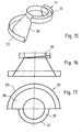
- a base 29 of a robot is shown.
- a device 30 for guiding and storing a line routing device 1 is formed in the region of the base 29.
- the device has a guide area 31 formed in a first level and a storage area 32 formed in a second level, which is different from the first level.
- the guide region 31 is essentially formed in a horizontal plane.
- the storage area 32 is formed in a substantially vertical plane.
- Figure 12 shows that the guide area is designed in the form of a groove.
- the guide region 31 surrounds the base 29 over its entire circumference. This is not absolutely necessary.
- the storage area 32 is essentially box-shaped.
- a transition area 33 is formed between the guide area 31 and the storage area 32.
- the line guide device (not shown) is inserted either into the guide region clockwise or counterclockwise, as indicated by the arrows in FIG Figure 12 is indicated.
- the guide area, the storage area and / or the transition area are at least partially designed as molded parts, in particular sheet metal molded parts.
- Figure 13 shows a perspective view of part of the guide area 31 and the transition area 33. A mirror axis is shown in broken lines so that the guide area and the storage area can be formed in mirror image.
- a circular insert 34 is arranged in the storage area 32, as shown in FIG Figure 11 can be seen.
- the device has a guide area 31 which, in the exemplary embodiment shown, partially surrounds the base 29 of the robot.
- the guide area 31 is U-shaped in cross section.
- the bottom 35 of the guide area 31 rises helically.
- the guide area 31 is connected to a storage area 32.
- the storage area 32 has a wall 36 which is frustoconical.
- An L-shaped boundary 37 is connected to the wall 36.
- the guide region 31 surrounds the base over an angle of approximately 180 °.
- the storage area 32 also surrounds the base over an angle of approximately 180 °.
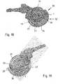
- FIGS. 18 and 19 snapshots of the position of a robot are shown.
- the robot has a base 29, which is surrounded by a device 30 for guiding and storing a cable routing device 1.
- the robot is over one Driver 38 connected to one end of the cable routing device 1.
- the opposite end 39 of the cable routing device 1 is arranged in a stationary manner.
- the line routing device 1 is located in the memory area 32.
- the lower run of the cable routing device lies in the boundary 37 and on the wall 36.
- the curved region of the cable routing device which lies between the lower run and the upper run, lies against the wall 36.
- the cable routing device 1 is preferably designed in such a way that the curved area of the cable routing device always comes into contact with the wall 36 by a corresponding design of the articulated connections between the members of the cable routing device, so that an additional cover, which could also be a guide, is dispensed with can. However, this is not absolutely necessary. Such a cover can also be useful for safety reasons.
- Figure 19 shows a snapshot in which the robot was rotated with the driver 38 in such a way that the driver 38 with the cable routing device 1 reaches the guide region 31.
- the cable routing device is guided in the guide area 31.
- the configuration of the device for guiding and storing the line routing device creates the possibility that the robot can drive over a circumferential angle of up to 360 ° with the driver 38.
Landscapes
- Engineering & Computer Science (AREA)
- General Engineering & Computer Science (AREA)
- Mechanical Engineering (AREA)
- Robotics (AREA)
- Architecture (AREA)
- Civil Engineering (AREA)
- Structural Engineering (AREA)
- Manipulator (AREA)
- Supports For Pipes And Cables (AREA)
Priority Applications (1)
| Application Number | Priority Date | Filing Date | Title |
|---|---|---|---|
| EP10164518.2A EP2226164B1 (de) | 2002-04-11 | 2003-03-28 | Roboter mit einer Leitungsführungseinrichtung |
Applications Claiming Priority (3)
| Application Number | Priority Date | Filing Date | Title |
|---|---|---|---|
| DE10216081A DE10216081B4 (de) | 2002-04-11 | 2002-04-11 | Roboter mit einer Leitungsführungseinrichtung |
| DE10216081 | 2002-04-11 | ||
| PCT/EP2003/003265 WO2003084721A2 (de) | 2002-04-11 | 2003-03-28 | Roboter mit einer leitungsführungseinrichtung |
Related Child Applications (2)
| Application Number | Title | Priority Date | Filing Date |
|---|---|---|---|
| EP10164518.2A Division-Into EP2226164B1 (de) | 2002-04-11 | 2003-03-28 | Roboter mit einer Leitungsführungseinrichtung |
| EP10164518.2A Division EP2226164B1 (de) | 2002-04-11 | 2003-03-28 | Roboter mit einer Leitungsführungseinrichtung |
Publications (3)
| Publication Number | Publication Date |
|---|---|
| EP1492967A2 EP1492967A2 (de) | 2005-01-05 |
| EP1492967B1 EP1492967B1 (de) | 2010-06-02 |
| EP1492967B2 true EP1492967B2 (de) | 2020-08-05 |
Family
ID=28684960
Family Applications (2)
| Application Number | Title | Priority Date | Filing Date |
|---|---|---|---|
| EP10164518.2A Expired - Lifetime EP2226164B1 (de) | 2002-04-11 | 2003-03-28 | Roboter mit einer Leitungsführungseinrichtung |
| EP03745774.4A Expired - Lifetime EP1492967B2 (de) | 2002-04-11 | 2003-03-28 | Roboter mit einer leitungsführungseinrichtung |
Family Applications Before (1)
| Application Number | Title | Priority Date | Filing Date |
|---|---|---|---|
| EP10164518.2A Expired - Lifetime EP2226164B1 (de) | 2002-04-11 | 2003-03-28 | Roboter mit einer Leitungsführungseinrichtung |
Country Status (9)
| Country | Link |
|---|---|
| US (1) | US7278253B2 (zh) |
| EP (2) | EP2226164B1 (zh) |
| JP (1) | JP4756495B2 (zh) |
| KR (1) | KR100902968B1 (zh) |
| CN (1) | CN1294368C (zh) |
| AU (1) | AU2003226740A1 (zh) |
| DE (2) | DE10216081B4 (zh) |
| TW (1) | TWI318273B (zh) |
| WO (1) | WO2003084721A2 (zh) |
Families Citing this family (48)
| Publication number | Priority date | Publication date | Assignee | Title |
|---|---|---|---|---|
| DE20305679U1 (de) * | 2003-04-07 | 2003-06-18 | Igus Gmbh | Kabelführung |
| DE102004026573A1 (de) * | 2004-06-01 | 2005-12-29 | Dürr Systems GmbH | Schlauchführungselement für einen Lackierroboter |
| DE102004033330A1 (de) * | 2004-07-09 | 2006-02-02 | Dürr Systems GmbH | Schlauchführung für einen Lackierroboter |
| DE202005001651U1 (de) * | 2005-02-01 | 2006-06-08 | Kabelschlepp Gmbh | Führungseinheit sowie Führungseinrichtung zum Führen einer Energieführungseinheit |
| JP4376822B2 (ja) * | 2005-04-22 | 2009-12-02 | 川崎重工業株式会社 | 変形構造体およびケーブルの支持装置 |
| ATE402356T1 (de) * | 2006-02-27 | 2008-08-15 | Bauer Maschinen Gmbh | Versorgungsband |
| KR100661773B1 (ko) | 2006-05-25 | 2006-12-28 | 김두진 | 로보체인의 링크플레이트 결합구조 |
| JP4758850B2 (ja) * | 2006-08-14 | 2011-08-31 | 矢崎総業株式会社 | リンクへのワイヤハーネスの配索構造 |
| DE502006006292D1 (de) * | 2006-09-27 | 2010-04-08 | Leoni Protec Cable Systems Gmb | Gungsleitung aufweisenden schlauches |
| EP2079564B1 (en) | 2006-10-24 | 2013-04-24 | Carnegie Mellon University | Steerable multi-linked device having a modular link assembly |
| DE102007007829A1 (de) * | 2007-02-16 | 2008-08-21 | Kuka Roboter Gmbh | Haltevorrichtung für ein Schlauchpaket für Industrieroboter |
| DE102007041663A1 (de) * | 2007-09-03 | 2009-03-05 | Kabelschlepp Gmbh | Einrichtung zum Führen von Leitungen, Schläuchen oder dergleichen |
| JP5507450B2 (ja) * | 2008-05-09 | 2014-05-28 | 川崎重工業株式会社 | 物品搬送ロボット装置 |
| EP2330965B1 (en) | 2008-09-05 | 2018-07-11 | Carnegie Mellon University | Multi-linked endoscopic device with spherical distal assembly |
| DE202008015076U1 (de) | 2008-11-13 | 2009-02-19 | Kabelschlepp Gmbh | Zugentlastungseinheit für eine Energieführungseinheit |
| CN101774178A (zh) | 2009-01-09 | 2010-07-14 | 鸿富锦精密工业(深圳)有限公司 | 机械手臂 |
| TWI419779B (zh) * | 2009-01-22 | 2013-12-21 | Hon Hai Prec Ind Co Ltd | 機械手臂 |
| DE202009005546U1 (de) * | 2009-04-16 | 2009-06-18 | Igus Gmbh | Kabelführung |
| DE102009029957B4 (de) * | 2009-06-19 | 2011-12-22 | Maximilian Rüttiger | Koppelbares Kettenglied einer Leitungsführungskette |
| DE202010007251U1 (de) | 2010-05-26 | 2010-10-28 | Kabelschlepp Gmbh | Leitungsführungseinrichtung mit einer Rückstelleinheit und Roboter mit einer solchen Leitungsführungseinrichtung |
| DE102010032921A1 (de) * | 2010-07-30 | 2012-04-19 | Kabelschlepp Gmbh | Leitungsführungseinrichtung mit einer Kugel-Seilverbindung |
| DE102010032920C5 (de) | 2010-07-30 | 2023-03-02 | Tsubaki Kabelschlepp GmbH | Räumlich auslenkbare Leitungsführungseinrichtung mit Krümmungsradiusbegrenzern |
| US8297560B2 (en) * | 2010-08-10 | 2012-10-30 | Modernsolid Industrial Co., Ltd. | Line-management assembly |
| DE202011101573U1 (de) * | 2011-05-30 | 2012-09-04 | Tsubaki Kabelschlepp GmbH | Bauteil für ein Leitungsführungssystem umfassend zumindest eine Leitungsführungseinrichtung sowie eine entsprechende Leitungsführungseinrichtung und Leitungsführungssystem |
| JP6184161B2 (ja) * | 2012-07-12 | 2017-08-23 | キヤノン株式会社 | ロボット |
| JP5591894B2 (ja) | 2012-09-26 | 2014-09-17 | ファナック株式会社 | ロボットの線条体取付装置 |
| DE202013101460U1 (de) * | 2013-04-05 | 2013-04-22 | Igus Gmbh | Leitungsführung aus mehrachsig abwinkelbaren Gliedern |
| DE102014107232A1 (de) | 2014-05-22 | 2015-11-26 | Tsubaki Kabelschlepp GmbH | Räumlich auslenkbare Leitungsführungseinrichtung |
| JP6505999B2 (ja) * | 2014-09-05 | 2019-04-24 | ファナック株式会社 | 弾性体を介して線条体を固定する線条体固定装置 |
| DE102015211496A1 (de) | 2015-06-22 | 2016-12-22 | Deckel Maho Pfronten Gmbh | Werkzeugmaschine zur spanenden Bearbeitung eines Werkstücks |
| US10444459B2 (en) | 2015-10-19 | 2019-10-15 | Commscope Technologies Llc | Articulating optical fiber guide system |
| JP6441254B2 (ja) * | 2016-04-05 | 2018-12-19 | ファナック株式会社 | ロボットの線条体処理構造 |
| ITUA20163371A1 (it) * | 2016-05-12 | 2017-11-12 | Findalto S R L | Catena portacavi snodata su piu' assi |
| DE102016214874A1 (de) * | 2016-08-10 | 2018-02-15 | Trumpf Werkzeugmaschinen Gmbh + Co. Kg | Industrieroboter für die Materialbearbeitung |
| DE202017102310U1 (de) * | 2017-04-19 | 2017-08-11 | Igus Gmbh | Magazinvorrichtung für Leitungen und Leitungsführungseinrichtungen |
| JP2019069456A (ja) * | 2017-10-06 | 2019-05-09 | アイダエンジニアリング株式会社 | プレス機械のワーク搬送装置 |
| JP6739105B2 (ja) * | 2017-11-06 | 2020-08-12 | 株式会社国盛化学 | ケーブル保護装置 |
| KR101999347B1 (ko) | 2018-04-09 | 2019-07-11 | 전남대학교산학협력단 | 다자유도 가요성 로봇 |
| DE202018103418U1 (de) * | 2018-06-18 | 2018-12-19 | Igus Gmbh | Leitungsführungseinrichtung für hängende Anwendungen, insbesondere als Service-Loop für eine Bohranlage |
| JP2020151802A (ja) * | 2019-03-20 | 2020-09-24 | ファナック株式会社 | ロボットの線条体処理構造 |
| US11258242B2 (en) * | 2019-08-13 | 2022-02-22 | BL United, LLC | Modular conduit cable management assembly |
| DE202020104482U1 (de) * | 2020-08-03 | 2021-09-06 | Igus Gmbh | Leitungsführungseinrichtung für hängende Anwendungen, insbesondere Bohranlagen, Bohrgeräte oder dgl. |
| DE202020106401U1 (de) * | 2020-11-06 | 2021-12-07 | Igus Gmbh | Ausgabevorrichtung für eine flexible Leitungsanordnung und Leitungsführungseinrichtung mit Fördereinheit |
| CN112952727B (zh) * | 2021-02-07 | 2022-09-09 | 中国科学院合肥物质科学研究院 | 一种大容量旋转拖链 |
| DE202021100995U1 (de) | 2021-02-26 | 2022-05-30 | Igus Gmbh | Räumlich auslenkbare Leitungsführungseinrichtung, insbesondere für einen Roboter |
| DE102021130256A1 (de) | 2021-11-19 | 2023-05-25 | Murrplastik Systemtechnik Gmbh | Protektor |
| CN114877024A (zh) * | 2022-04-26 | 2022-08-09 | 河北永明地质工程机械有限公司 | 链节单体、链节组件及拖链组件 |
| DE202022103458U1 (de) | 2022-06-21 | 2023-09-26 | Igus Gmbh | Energieführungskette mit Zugseil-Detektoranordnung |
Citations (1)
| Publication number | Priority date | Publication date | Assignee | Title |
|---|---|---|---|---|
| DE3419877A1 (de) † | 1983-06-06 | 1984-12-20 | Sine Products Co., Mt. Clemens, Mich. | Handhabungseinrichtung |
Family Cites Families (33)
| Publication number | Priority date | Publication date | Assignee | Title |
|---|---|---|---|---|
| FR1365129A (fr) | 1963-08-02 | 1964-06-26 | Avica Equip | Conduites métalliques souples |
| US4739801A (en) | 1985-04-09 | 1988-04-26 | Tysubakimoto Chain Co. | Flexible supporting sheath for cables and the like |
| IT208046Z2 (it) | 1986-09-15 | 1988-03-31 | Tecno Mobili E Forniture Per A | Organo passocavo flessibile a snodi bidirezionali. |
| IT209828Z2 (it) * | 1987-01-02 | 1988-11-04 | Mauri Giovanni | Catena portacavi a sviluppo curvilineo.! |
| US5824957A (en) * | 1991-09-03 | 1998-10-20 | Technology Finance Corporation (Proprietary) Limited | Electrical cable containment |
| CA2116860A1 (en) | 1991-09-03 | 1993-03-18 | Nicholas Hugo Holshausen | Electrical cable containment |
| JP2526509B2 (ja) * | 1993-10-14 | 1996-08-21 | マルホ産業株式会社 | 地中電線埋設自在保護管 |
| EP0676840B1 (de) | 1994-04-11 | 1999-08-18 | Wilma Elkuch-Ganter | Flexibles Kabelschutzrohr |
| DE4426598C1 (de) | 1994-07-27 | 1995-12-21 | Bauer Spezialtiefbau | Schlauchkette |
| DK0787377T3 (da) * | 1994-10-18 | 1999-04-19 | President Office Furniture Ltd | Piedestal-tilførselsenhed |
| DE19617900A1 (de) | 1995-05-10 | 1996-12-05 | Ernst Moeckl | Kabelkette |
| US5836148A (en) | 1996-02-06 | 1998-11-17 | Kunimorikagaku Ltd. | Cable chain |
| DE19710489A1 (de) | 1997-03-13 | 1998-09-24 | Kabelschlepp Gmbh | Faltbares Schutzelement für Leitungen |
| DE19716695C1 (de) | 1997-04-21 | 1998-12-10 | Kabelschlepp Gmbh | Energieführungskette zum stationären Führen von Leitungen |
| DK174401B1 (da) * | 1997-05-15 | 2003-02-10 | Raunkjaer Hans Thyge | System til fremføring af bundter af ledninger |
| DE19728284C2 (de) | 1997-07-02 | 1999-11-18 | Dlw Bueroeinrichtungen Gmbh | Elektrifiziereinrichtung für ein Büromöbel |
| DE29814417U1 (de) | 1998-08-11 | 1998-10-08 | Kuka Roboter Gmbh | Schlauchhalter |
| DE19860948C2 (de) | 1998-12-31 | 2002-02-14 | Igus Gmbh | Leitungsführungseinrichtung |
| DE29904652U1 (de) | 1999-03-14 | 2000-04-20 | Hopmann Gero | Kettenglied und Kette |
| DE29904796U1 (de) | 1999-03-17 | 1999-07-08 | Ruettiger | Energieführungsketten-System |
| CN1123711C (zh) * | 1999-04-19 | 2003-10-08 | Igus工业用注压件有限公司 | 电缆导链 |
| DE29913063U1 (de) * | 1999-07-30 | 2000-02-17 | Igus Gmbh | Energiezuführungskette |
| EP1227998B1 (en) * | 1999-08-11 | 2003-12-17 | Akzo Nobel N.V. | PROCESS FOR PRODUCING Al-CONTAINING NON-Mg-ANIONIC CLAY |
| DE20007000U1 (de) | 2000-04-15 | 2001-06-21 | Kuka Roboter Gmbh | Roboter mit außenseitig verlaufendem Schutzschlauch |
| DE10018773A1 (de) * | 2000-04-15 | 2001-10-25 | Kuka Roboter Gmbh | Roboter |
| DE20008054U1 (de) * | 2000-05-05 | 2001-06-21 | Kuka Roboter Gmbh | Schlauchführung im Sockel eines Roboters |
| DE20014649U1 (de) | 2000-08-24 | 2001-09-27 | Kuka Roboter Gmbh | Vorrichtung zum Festlegen eines Kabelführungsschlauchs |
| DE20010696U1 (de) * | 2000-06-15 | 2001-07-26 | Kuka Roboter Gmbh | Vorrichtung zum Festlegen von Kabeln eines Kabelführungsschlauchs |
| DE20012232U1 (de) | 2000-07-14 | 2000-11-09 | Protec Kabel Produktion Gmbh | Rundkorb zur Ablage freigeführter Wellschläuche |
| DE20113950U1 (de) * | 2001-03-16 | 2001-11-08 | Ernst & Engbring Gmbh & Co Kg | Vorrichtung zum Führen und/oder Spannen eines Leitungsbündels bei einem Roboter |
| DE20113962U1 (de) | 2001-04-19 | 2001-11-08 | Ernst & Engbring Gmbh & Co Kg | Vorrichtung zum Halten eines Leitungsbündels bei einem Roboter |
| DE20112491U1 (de) * | 2001-07-28 | 2001-10-18 | Leoni Protec Cable Systems Gmb | Leitungsführung bei einem mehrachsigen Industrieroboter |
| DE20113742U1 (de) | 2001-08-27 | 2001-11-08 | Leoni Protec Cable Systems Gmb | Leitungsführung bei einem Industrieroboter |
-
2002
- 2002-04-11 DE DE10216081A patent/DE10216081B4/de not_active Expired - Fee Related
-
2003
- 2003-03-13 TW TW092105507A patent/TWI318273B/zh not_active IP Right Cessation
- 2003-03-28 JP JP2003581947A patent/JP4756495B2/ja not_active Expired - Lifetime
- 2003-03-28 DE DE50312770T patent/DE50312770D1/de not_active Expired - Lifetime
- 2003-03-28 WO PCT/EP2003/003265 patent/WO2003084721A2/de active Application Filing
- 2003-03-28 EP EP10164518.2A patent/EP2226164B1/de not_active Expired - Lifetime
- 2003-03-28 KR KR1020047015847A patent/KR100902968B1/ko not_active IP Right Cessation
- 2003-03-28 CN CNB038081997A patent/CN1294368C/zh not_active Expired - Fee Related
- 2003-03-28 EP EP03745774.4A patent/EP1492967B2/de not_active Expired - Lifetime
- 2003-03-28 US US10/510,595 patent/US7278253B2/en not_active Expired - Lifetime
- 2003-03-28 AU AU2003226740A patent/AU2003226740A1/en not_active Abandoned
Patent Citations (1)
| Publication number | Priority date | Publication date | Assignee | Title |
|---|---|---|---|---|
| DE3419877A1 (de) † | 1983-06-06 | 1984-12-20 | Sine Products Co., Mt. Clemens, Mich. | Handhabungseinrichtung |
Also Published As
| Publication number | Publication date |
|---|---|
| EP1492967B1 (de) | 2010-06-02 |
| WO2003084721A2 (de) | 2003-10-16 |
| DE50312770D1 (de) | 2010-07-15 |
| WO2003084721A3 (de) | 2003-11-27 |
| KR20050003345A (ko) | 2005-01-10 |
| AU2003226740A8 (en) | 2003-10-20 |
| CN1646828A (zh) | 2005-07-27 |
| DE10216081A1 (de) | 2003-10-30 |
| AU2003226740A1 (en) | 2003-10-20 |
| KR100902968B1 (ko) | 2009-06-15 |
| EP2226164A1 (de) | 2010-09-08 |
| US20050172606A1 (en) | 2005-08-11 |
| CN1294368C (zh) | 2007-01-10 |
| EP1492967A2 (de) | 2005-01-05 |
| TWI318273B (en) | 2009-12-11 |
| US7278253B2 (en) | 2007-10-09 |
| JP4756495B2 (ja) | 2011-08-24 |
| TW200404654A (en) | 2004-04-01 |
| DE10216081B4 (de) | 2005-03-31 |
| EP2226164B1 (de) | 2014-11-26 |
| JP2005522753A (ja) | 2005-07-28 |
Similar Documents
| Publication | Publication Date | Title |
|---|---|---|
| EP1492967B2 (de) | Roboter mit einer leitungsführungseinrichtung | |
| EP2069113B1 (de) | Vorrichtung zum führen eines zumindest eine versorgungsleitung aufweisenden schlauches | |
| EP1369211B1 (de) | Vorrichtung zum Führen und Zurückholen eines Schlauches eines Industrieroboters | |
| EP0599784B1 (de) | Buchsenteil für eine Lichtwellenleiter-Steckverbindung | |
| EP1108157B1 (de) | Energieführungskette zum führen von leitungen mit räumlich beweglichen kettengliedern | |
| DE102008004576B4 (de) | Schutz- und Führungsvorrichtung für ein Kabel | |
| DE102008020908A1 (de) | Schutz- und Führungsvorrichtung für ein Kabel oder dergleichen | |
| EP3020107B1 (de) | Einrichtung zur fixierung und/oder führung von strangförmigen elementen | |
| DE102012106784A1 (de) | Energieführungskette für Kabel oder dergleichen | |
| DE102007061296A1 (de) | Schutz- und Führungsvorrichtung für ein Kabel oder dergleichen | |
| WO2013124370A2 (de) | Kabelführung | |
| EP3347222B1 (de) | Fahrzeugdach mit einem beweglichen dachteil | |
| EP2136963B1 (de) | Gliederschürze | |
| DE4124281A1 (de) | Druck/zug-kette und ein diese kette verwendendes geraet mit hin- und herbewegung | |
| EP2784222B1 (de) | Leitplankenvorrichtung, insbesondere Leitplankenüberleitungssystem, mit Verriegelungseinheit und Kurzabsenkung | |
| EP1963709B1 (de) | Kettenglied mit einer mehrachsigen gelenkverbindung | |
| EP2263450A1 (de) | Futtermischer | |
| DE10231724B4 (de) | Halteschelle | |
| EP1985502B1 (de) | Kabelführung in einer Antriebseinheit eines deichselgelenkten Flurförderzeugs | |
| EP1893419B1 (de) | Gleitschutzvorrichtung | |
| EP3685944B1 (de) | Tubenhalter für eine tubenfüllmaschine | |
| DE2357908C3 (de) | Gliederkette, insbesondere zum Führen von flexiblen Versorgungsleitungen von einem ortsfesten Anschluß zu einem beweglichen Verbraucher | |
| DE19952699B4 (de) | Energieführungskette | |
| DE102014102626A1 (de) | Kettenglied für eine Energieführungskette | |
| WO2001040676A1 (de) | Energieführungseinheit |
Legal Events
| Date | Code | Title | Description |
|---|---|---|---|
| PUAI | Public reference made under article 153(3) epc to a published international application that has entered the european phase |
Free format text: ORIGINAL CODE: 0009012 |
|
| 17P | Request for examination filed |
Effective date: 20041015 |
|
| AK | Designated contracting states |
Kind code of ref document: A2 Designated state(s): AT BE BG CH CY CZ DE DK EE ES FI FR GB GR HU IE IT LI LU MC NL PT RO SE SI SK TR |
|
| AX | Request for extension of the european patent |
Extension state: AL LT LV MK |
|
| RAP1 | Party data changed (applicant data changed or rights of an application transferred) |
Owner name: KABELSCHLEPP GMBH |
|
| GRAP | Despatch of communication of intention to grant a patent |
Free format text: ORIGINAL CODE: EPIDOSNIGR1 |
|
| RIC1 | Information provided on ipc code assigned before grant |
Ipc: B25J 19/00 20060101AFI20091126BHEP |
|
| GRAS | Grant fee paid |
Free format text: ORIGINAL CODE: EPIDOSNIGR3 |
|
| GRAA | (expected) grant |
Free format text: ORIGINAL CODE: 0009210 |
|
| AK | Designated contracting states |
Kind code of ref document: B1 Designated state(s): DE FR GB IT SE |
|
| REG | Reference to a national code |
Ref country code: GB Ref legal event code: FG4D Free format text: NOT ENGLISH |
|
| REF | Corresponds to: |
Ref document number: 50312770 Country of ref document: DE Date of ref document: 20100715 Kind code of ref document: P |
|
| PG25 | Lapsed in a contracting state [announced via postgrant information from national office to epo] |
Ref country code: SE Free format text: LAPSE BECAUSE OF FAILURE TO SUBMIT A TRANSLATION OF THE DESCRIPTION OR TO PAY THE FEE WITHIN THE PRESCRIBED TIME-LIMIT Effective date: 20100602 |
|
| PLBI | Opposition filed |
Free format text: ORIGINAL CODE: 0009260 |
|
| PLAX | Notice of opposition and request to file observation + time limit sent |
Free format text: ORIGINAL CODE: EPIDOSNOBS2 |
|
| 26 | Opposition filed |
Opponent name: IGUS GMBH Effective date: 20110225 |
|
| REG | Reference to a national code |
Ref country code: DE Ref legal event code: R026 Ref document number: 50312770 Country of ref document: DE Effective date: 20110225 |
|
| PLBB | Reply of patent proprietor to notice(s) of opposition received |
Free format text: ORIGINAL CODE: EPIDOSNOBS3 |
|
| GBPC | Gb: european patent ceased through non-payment of renewal fee |
Effective date: 20110328 |
|
| REG | Reference to a national code |
Ref country code: FR Ref legal event code: ST Effective date: 20111130 |
|
| PG25 | Lapsed in a contracting state [announced via postgrant information from national office to epo] |
Ref country code: FR Free format text: LAPSE BECAUSE OF NON-PAYMENT OF DUE FEES Effective date: 20110331 |
|
| PG25 | Lapsed in a contracting state [announced via postgrant information from national office to epo] |
Ref country code: GB Free format text: LAPSE BECAUSE OF NON-PAYMENT OF DUE FEES Effective date: 20110328 |
|
| RIC2 | Information provided on ipc code assigned after grant |
Ipc: B25J 19/00 20060101AFI20151222BHEP Ipc: F16G 13/16 20060101ALI20151222BHEP Ipc: H02G 11/00 20060101ALI20151222BHEP |
|
| APAH | Appeal reference modified |
Free format text: ORIGINAL CODE: EPIDOSCREFNO |
|
| APBM | Appeal reference recorded |
Free format text: ORIGINAL CODE: EPIDOSNREFNO |
|
| APBP | Date of receipt of notice of appeal recorded |
Free format text: ORIGINAL CODE: EPIDOSNNOA2O |
|
| APBQ | Date of receipt of statement of grounds of appeal recorded |
Free format text: ORIGINAL CODE: EPIDOSNNOA3O |
|
| PLAB | Opposition data, opponent's data or that of the opponent's representative modified |
Free format text: ORIGINAL CODE: 0009299OPPO |
|
| R26 | Opposition filed (corrected) |
Opponent name: IGUS GMBH Effective date: 20110225 |
|
| APBU | Appeal procedure closed |
Free format text: ORIGINAL CODE: EPIDOSNNOA9O |
|
| PUAH | Patent maintained in amended form |
Free format text: ORIGINAL CODE: 0009272 |
|
| STAA | Information on the status of an ep patent application or granted ep patent |
Free format text: STATUS: PATENT MAINTAINED AS AMENDED |
|
| 27A | Patent maintained in amended form |
Effective date: 20200805 |
|
| AK | Designated contracting states |
Kind code of ref document: B2 Designated state(s): DE FR GB IT SE |
|
| REG | Reference to a national code |
Ref country code: DE Ref legal event code: R102 Ref document number: 50312770 Country of ref document: DE |
|
| PGFP | Annual fee paid to national office [announced via postgrant information from national office to epo] |
Ref country code: IT Payment date: 20210331 Year of fee payment: 19 |
|
| PGFP | Annual fee paid to national office [announced via postgrant information from national office to epo] |
Ref country code: DE Payment date: 20220830 Year of fee payment: 20 |
|
| REG | Reference to a national code |
Ref country code: DE Ref legal event code: R071 Ref document number: 50312770 Country of ref document: DE |
|
| PG25 | Lapsed in a contracting state [announced via postgrant information from national office to epo] |
Ref country code: IT Free format text: LAPSE BECAUSE OF NON-PAYMENT OF DUE FEES Effective date: 20220328 |