EP1487021A1 - Semiconductor device - Google Patents
Semiconductor device Download PDFInfo
- Publication number
- EP1487021A1 EP1487021A1 EP02716404A EP02716404A EP1487021A1 EP 1487021 A1 EP1487021 A1 EP 1487021A1 EP 02716404 A EP02716404 A EP 02716404A EP 02716404 A EP02716404 A EP 02716404A EP 1487021 A1 EP1487021 A1 EP 1487021A1
- Authority
- EP
- European Patent Office
- Prior art keywords
- impurity
- impurity region
- type
- region
- semiconductor device
- Prior art date
- Legal status (The legal status is an assumption and is not a legal conclusion. Google has not performed a legal analysis and makes no representation as to the accuracy of the status listed.)
- Withdrawn
Links
- 239000004065 semiconductor Substances 0.000 title claims abstract description 78
- 239000012535 impurity Substances 0.000 claims abstract description 139
- 230000015556 catabolic process Effects 0.000 claims abstract description 92
- 239000000758 substrate Substances 0.000 claims abstract description 29
- 230000002093 peripheral effect Effects 0.000 claims description 8
- 230000005669 field effect Effects 0.000 claims description 3
- 238000009792 diffusion process Methods 0.000 abstract description 110
- 230000002349 favourable effect Effects 0.000 abstract description 6
- XUIMIQQOPSSXEZ-UHFFFAOYSA-N Silicon Chemical compound [Si] XUIMIQQOPSSXEZ-UHFFFAOYSA-N 0.000 description 18
- 229910052710 silicon Inorganic materials 0.000 description 18
- 239000010703 silicon Substances 0.000 description 18
- 230000005684 electric field Effects 0.000 description 10
- 210000000746 body region Anatomy 0.000 description 9
- 230000000694 effects Effects 0.000 description 9
- 238000009826 distribution Methods 0.000 description 8
- 230000008859 change Effects 0.000 description 6
- VYPSYNLAJGMNEJ-UHFFFAOYSA-N Silicium dioxide Chemical compound O=[Si]=O VYPSYNLAJGMNEJ-UHFFFAOYSA-N 0.000 description 5
- 229910052698 phosphorus Inorganic materials 0.000 description 5
- 229910052814 silicon oxide Inorganic materials 0.000 description 5
- 238000004088 simulation Methods 0.000 description 5
- 229910052796 boron Inorganic materials 0.000 description 4
- 150000002500 ions Chemical class 0.000 description 4
- 239000000463 material Substances 0.000 description 4
- 239000011574 phosphorus Substances 0.000 description 4
- ZOXJGFHDIHLPTG-UHFFFAOYSA-N Boron Chemical compound [B] ZOXJGFHDIHLPTG-UHFFFAOYSA-N 0.000 description 3
- OAICVXFJPJFONN-UHFFFAOYSA-N Phosphorus Chemical compound [P] OAICVXFJPJFONN-UHFFFAOYSA-N 0.000 description 3
- 238000005229 chemical vapour deposition Methods 0.000 description 3
- 230000006872 improvement Effects 0.000 description 3
- -1 monocrystal Chemical compound 0.000 description 3
- 230000007423 decrease Effects 0.000 description 2
- 230000003247 decreasing effect Effects 0.000 description 2
- 239000012212 insulator Substances 0.000 description 2
- 238000004519 manufacturing process Methods 0.000 description 2
- 238000000034 method Methods 0.000 description 2
- 230000008569 process Effects 0.000 description 2
- 230000008901 benefit Effects 0.000 description 1
- 230000015572 biosynthetic process Effects 0.000 description 1
- 238000006731 degradation reaction Methods 0.000 description 1
- 230000001419 dependent effect Effects 0.000 description 1
- 238000005530 etching Methods 0.000 description 1
- 230000001747 exhibiting effect Effects 0.000 description 1
- 238000010438 heat treatment Methods 0.000 description 1
- 230000001939 inductive effect Effects 0.000 description 1
- 229910044991 metal oxide Inorganic materials 0.000 description 1
- 150000004706 metal oxides Chemical class 0.000 description 1
- 239000013081 microcrystal Substances 0.000 description 1
- 230000004048 modification Effects 0.000 description 1
- 238000012986 modification Methods 0.000 description 1
Images


Classifications
-
- H—ELECTRICITY
- H01—ELECTRIC ELEMENTS
- H01L—SEMICONDUCTOR DEVICES NOT COVERED BY CLASS H10
- H01L29/00—Semiconductor devices specially adapted for rectifying, amplifying, oscillating or switching and having potential barriers; Capacitors or resistors having potential barriers, e.g. a PN-junction depletion layer or carrier concentration layer; Details of semiconductor bodies or of electrodes thereof ; Multistep manufacturing processes therefor
- H01L29/66—Types of semiconductor device ; Multistep manufacturing processes therefor
- H01L29/68—Types of semiconductor device ; Multistep manufacturing processes therefor controllable by only the electric current supplied, or only the electric potential applied, to an electrode which does not carry the current to be rectified, amplified or switched
- H01L29/76—Unipolar devices, e.g. field effect transistors
- H01L29/772—Field effect transistors
- H01L29/78—Field effect transistors with field effect produced by an insulated gate
- H01L29/7801—DMOS transistors, i.e. MISFETs with a channel accommodating body or base region adjoining a drain drift region
- H01L29/7802—Vertical DMOS transistors, i.e. VDMOS transistors
- H01L29/7811—Vertical DMOS transistors, i.e. VDMOS transistors with an edge termination structure
-
- H—ELECTRICITY
- H01—ELECTRIC ELEMENTS
- H01L—SEMICONDUCTOR DEVICES NOT COVERED BY CLASS H10
- H01L29/00—Semiconductor devices specially adapted for rectifying, amplifying, oscillating or switching and having potential barriers; Capacitors or resistors having potential barriers, e.g. a PN-junction depletion layer or carrier concentration layer; Details of semiconductor bodies or of electrodes thereof ; Multistep manufacturing processes therefor
- H01L29/66—Types of semiconductor device ; Multistep manufacturing processes therefor
- H01L29/68—Types of semiconductor device ; Multistep manufacturing processes therefor controllable by only the electric current supplied, or only the electric potential applied, to an electrode which does not carry the current to be rectified, amplified or switched
- H01L29/76—Unipolar devices, e.g. field effect transistors
- H01L29/772—Field effect transistors
- H01L29/80—Field effect transistors with field effect produced by a PN or other rectifying junction gate, i.e. potential-jump barrier
-
- H—ELECTRICITY
- H01—ELECTRIC ELEMENTS
- H01L—SEMICONDUCTOR DEVICES NOT COVERED BY CLASS H10
- H01L29/00—Semiconductor devices specially adapted for rectifying, amplifying, oscillating or switching and having potential barriers; Capacitors or resistors having potential barriers, e.g. a PN-junction depletion layer or carrier concentration layer; Details of semiconductor bodies or of electrodes thereof ; Multistep manufacturing processes therefor
- H01L29/02—Semiconductor bodies ; Multistep manufacturing processes therefor
- H01L29/06—Semiconductor bodies ; Multistep manufacturing processes therefor characterised by their shape; characterised by the shapes, relative sizes, or dispositions of the semiconductor regions ; characterised by the concentration or distribution of impurities within semiconductor regions
- H01L29/0603—Semiconductor bodies ; Multistep manufacturing processes therefor characterised by their shape; characterised by the shapes, relative sizes, or dispositions of the semiconductor regions ; characterised by the concentration or distribution of impurities within semiconductor regions characterised by particular constructional design considerations, e.g. for preventing surface leakage, for controlling electric field concentration or for internal isolations regions
- H01L29/0607—Semiconductor bodies ; Multistep manufacturing processes therefor characterised by their shape; characterised by the shapes, relative sizes, or dispositions of the semiconductor regions ; characterised by the concentration or distribution of impurities within semiconductor regions characterised by particular constructional design considerations, e.g. for preventing surface leakage, for controlling electric field concentration or for internal isolations regions for preventing surface leakage or controlling electric field concentration
- H01L29/0611—Semiconductor bodies ; Multistep manufacturing processes therefor characterised by their shape; characterised by the shapes, relative sizes, or dispositions of the semiconductor regions ; characterised by the concentration or distribution of impurities within semiconductor regions characterised by particular constructional design considerations, e.g. for preventing surface leakage, for controlling electric field concentration or for internal isolations regions for preventing surface leakage or controlling electric field concentration for increasing or controlling the breakdown voltage of reverse biased devices
- H01L29/0615—Semiconductor bodies ; Multistep manufacturing processes therefor characterised by their shape; characterised by the shapes, relative sizes, or dispositions of the semiconductor regions ; characterised by the concentration or distribution of impurities within semiconductor regions characterised by particular constructional design considerations, e.g. for preventing surface leakage, for controlling electric field concentration or for internal isolations regions for preventing surface leakage or controlling electric field concentration for increasing or controlling the breakdown voltage of reverse biased devices by the doping profile or the shape or the arrangement of the PN junction, or with supplementary regions, e.g. junction termination extension [JTE]
- H01L29/063—Reduced surface field [RESURF] pn-junction structures
- H01L29/0634—Multiple reduced surface field (multi-RESURF) structures, e.g. double RESURF, charge compensation, cool, superjunction (SJ), 3D-RESURF, composite buffer (CB) structures
-
- H—ELECTRICITY
- H01—ELECTRIC ELEMENTS
- H01L—SEMICONDUCTOR DEVICES NOT COVERED BY CLASS H10
- H01L29/00—Semiconductor devices specially adapted for rectifying, amplifying, oscillating or switching and having potential barriers; Capacitors or resistors having potential barriers, e.g. a PN-junction depletion layer or carrier concentration layer; Details of semiconductor bodies or of electrodes thereof ; Multistep manufacturing processes therefor
- H01L29/66—Types of semiconductor device ; Multistep manufacturing processes therefor
- H01L29/68—Types of semiconductor device ; Multistep manufacturing processes therefor controllable by only the electric current supplied, or only the electric potential applied, to an electrode which does not carry the current to be rectified, amplified or switched
- H01L29/76—Unipolar devices, e.g. field effect transistors
- H01L29/772—Field effect transistors
- H01L29/78—Field effect transistors with field effect produced by an insulated gate
- H01L29/7801—DMOS transistors, i.e. MISFETs with a channel accommodating body or base region adjoining a drain drift region
- H01L29/7802—Vertical DMOS transistors, i.e. VDMOS transistors
- H01L29/7813—Vertical DMOS transistors, i.e. VDMOS transistors with trench gate electrode, e.g. UMOS transistors
-
- H—ELECTRICITY
- H01—ELECTRIC ELEMENTS
- H01L—SEMICONDUCTOR DEVICES NOT COVERED BY CLASS H10
- H01L29/00—Semiconductor devices specially adapted for rectifying, amplifying, oscillating or switching and having potential barriers; Capacitors or resistors having potential barriers, e.g. a PN-junction depletion layer or carrier concentration layer; Details of semiconductor bodies or of electrodes thereof ; Multistep manufacturing processes therefor
- H01L29/66—Types of semiconductor device ; Multistep manufacturing processes therefor
- H01L29/68—Types of semiconductor device ; Multistep manufacturing processes therefor controllable by only the electric current supplied, or only the electric potential applied, to an electrode which does not carry the current to be rectified, amplified or switched
- H01L29/76—Unipolar devices, e.g. field effect transistors
- H01L29/772—Field effect transistors
- H01L29/78—Field effect transistors with field effect produced by an insulated gate
- H01L29/7801—DMOS transistors, i.e. MISFETs with a channel accommodating body or base region adjoining a drain drift region
- H01L29/7816—Lateral DMOS transistors, i.e. LDMOS transistors
- H01L29/7824—Lateral DMOS transistors, i.e. LDMOS transistors with a substrate comprising an insulating layer, e.g. SOI-LDMOS transistors
-
- H—ELECTRICITY
- H01—ELECTRIC ELEMENTS
- H01L—SEMICONDUCTOR DEVICES NOT COVERED BY CLASS H10
- H01L29/00—Semiconductor devices specially adapted for rectifying, amplifying, oscillating or switching and having potential barriers; Capacitors or resistors having potential barriers, e.g. a PN-junction depletion layer or carrier concentration layer; Details of semiconductor bodies or of electrodes thereof ; Multistep manufacturing processes therefor
- H01L29/66—Types of semiconductor device ; Multistep manufacturing processes therefor
- H01L29/86—Types of semiconductor device ; Multistep manufacturing processes therefor controllable only by variation of the electric current supplied, or only the electric potential applied, to one or more of the electrodes carrying the current to be rectified, amplified, oscillated or switched
- H01L29/861—Diodes
-
- H—ELECTRICITY
- H01—ELECTRIC ELEMENTS
- H01L—SEMICONDUCTOR DEVICES NOT COVERED BY CLASS H10
- H01L21/00—Processes or apparatus adapted for the manufacture or treatment of semiconductor or solid state devices or of parts thereof
- H01L21/02—Manufacture or treatment of semiconductor devices or of parts thereof
- H01L21/04—Manufacture or treatment of semiconductor devices or of parts thereof the devices having potential barriers, e.g. a PN junction, depletion layer or carrier concentration layer
- H01L21/18—Manufacture or treatment of semiconductor devices or of parts thereof the devices having potential barriers, e.g. a PN junction, depletion layer or carrier concentration layer the devices having semiconductor bodies comprising elements of Group IV of the Periodic Table or AIIIBV compounds with or without impurities, e.g. doping materials
- H01L21/26—Bombardment with radiation
- H01L21/263—Bombardment with radiation with high-energy radiation
- H01L21/265—Bombardment with radiation with high-energy radiation producing ion implantation
- H01L21/26586—Bombardment with radiation with high-energy radiation producing ion implantation characterised by the angle between the ion beam and the crystal planes or the main crystal surface
-
- H—ELECTRICITY
- H01—ELECTRIC ELEMENTS
- H01L—SEMICONDUCTOR DEVICES NOT COVERED BY CLASS H10
- H01L29/00—Semiconductor devices specially adapted for rectifying, amplifying, oscillating or switching and having potential barriers; Capacitors or resistors having potential barriers, e.g. a PN-junction depletion layer or carrier concentration layer; Details of semiconductor bodies or of electrodes thereof ; Multistep manufacturing processes therefor
- H01L29/02—Semiconductor bodies ; Multistep manufacturing processes therefor
- H01L29/06—Semiconductor bodies ; Multistep manufacturing processes therefor characterised by their shape; characterised by the shapes, relative sizes, or dispositions of the semiconductor regions ; characterised by the concentration or distribution of impurities within semiconductor regions
- H01L29/0603—Semiconductor bodies ; Multistep manufacturing processes therefor characterised by their shape; characterised by the shapes, relative sizes, or dispositions of the semiconductor regions ; characterised by the concentration or distribution of impurities within semiconductor regions characterised by particular constructional design considerations, e.g. for preventing surface leakage, for controlling electric field concentration or for internal isolations regions
- H01L29/0642—Isolation within the component, i.e. internal isolation
- H01L29/0649—Dielectric regions, e.g. SiO2 regions, air gaps
- H01L29/0653—Dielectric regions, e.g. SiO2 regions, air gaps adjoining the input or output region of a field-effect device, e.g. the source or drain region
-
- H—ELECTRICITY
- H01—ELECTRIC ELEMENTS
- H01L—SEMICONDUCTOR DEVICES NOT COVERED BY CLASS H10
- H01L29/00—Semiconductor devices specially adapted for rectifying, amplifying, oscillating or switching and having potential barriers; Capacitors or resistors having potential barriers, e.g. a PN-junction depletion layer or carrier concentration layer; Details of semiconductor bodies or of electrodes thereof ; Multistep manufacturing processes therefor
- H01L29/40—Electrodes ; Multistep manufacturing processes therefor
- H01L29/408—Electrodes ; Multistep manufacturing processes therefor with an insulating layer with a particular dielectric or electrostatic property, e.g. with static charges or for controlling trapped charges or moving ions, or with a plate acting on the insulator potential or the insulator charges, e.g. for controlling charges effect or potential distribution in the insulating layer, or with a semi-insulating layer contacting directly the semiconductor surface
Definitions
- the present invention relates to a semiconductor device, and more particularly to improvement in performance of a semiconductor device using a RESURF effect.
- a device employing a repeat structure of n type and p type layers of fine size (hereinafter, referred to as the "pn repeat structure") applying field relaxation phenomena called a RESURF (Reduced SURface Field) effect, in place of a uniform n type drift layer of a conventional MOSFET (Metal Oxide Semiconductor Field Effect Transistor), has been proposed, e.g., in USP 6,040,600.
- RESURF Reduced SURface Field
- the drift layers are likely to experience depletion, which is advantageous in that impurity concentrations of the drift layers can be increased and thus on-state resistance can be reduced.
- an STM (Super Trench power MOSFET) structure is obtained which can achieve a breakdown voltage several times greater than a main breakdown voltage normally obtained with a single n type drift layer of high concentration.
- STM structure disclosed in USP 6,040,600 is described as a conventional example.
- Fig. 19 is a schematic cross sectional view of a conventional STM structure.
- a first main surface of a semiconductor substrate 101 is provided with a plurality of repeated trenches 101a.
- n type and p type diffusion regions 103 and 104 are provided within a region sandwiched between trenches 101a.
- N type diffusion region 103 is provided on a sidewall surface of one trench 101a and p type diffusion region 104 is provided on a sidewall surface of another trench 101a.
- N type and p type diffusion regions 103 and 104 constitute a pn junction along a depth direction of trench 101a.
- a p type body region 105 is formed on the first main surface side of n type and p type diffusion regions 103, 104.
- a source n + diffusion region 106 is provided within p type body region 105 on the sidewall surface of one trench 101a.
- a gate electrode layer 109 is formed along the sidewall surface of one trench 101a such that gate electrode layer 109 is opposite to p type body region 105 sandwiched between source n + diffusion region 106 and n type diffusion region 103, with a gate insulating layer 108 disposed between p type body region 105 and gate electrode layer 109.
- Trench 101a is filled with a filling layer 110 formed of an insulator.
- a p + diffusion region 107 is provided on the first main surface side of filling layer 110 and is in contact with p type body region 105.
- an n + region of semiconductor substrate 101 is located on a second main surface side of the repeat structure consisting of n type and p type diffusion regions 103, 104 and trenches 101a.
- a source electrode layer 111 is formed on the first main surface to electrically connect with p type body region 105, source n + diffusion region 106 and p + diffusion region 107.
- a drain electrode layer 112 is formed on the second main surface to electrically connect with n + region 101.
- total amounts of charges in neighboring n type and p type diffusion region 103 and 104 are made equal to each other to assure a high breakdown voltage.
- n type and p type diffusion regions 103, 104 adjacent to each other have equal total charge amounts, however, electric field strength upon avalanche breakdown (when held at a main breakdown voltage) would become approximately uniform in a region for forming n type and p type diffusion regions 103, 104. In such a case, an avalanche current would cause positive feedback, undesirably decreasing avalanche breakdown tolerance (non-clamp inductive load switching breakdown tolerance).
- the STM As shown in Fig. 19, impurities within n type and p type diffusion regions 103, 104 are localized in the vicinity of the sidewalls of trenches 101a, as shown in Fig. 20.
- a current flows locally in the vicinity of the sidewalls of trenches 101a, as shown in Fig. 21.
- the STM has an effective current density greater than that of another device having a uniform drift concentration, making the STM particularly inferior in avalanche breakdown tolerance.
- Fig. 21 shows the simulation result, in which regions having high dot distribution densities within n type and p type diffusion regions 103, 104 each correspond to a region of high current density.
- An object of the present invention is, in an STM or multi RESURF type semiconductor device where a current flow is localized to a sidewall of a trench upon avalanche breakdown, to maintain a high breakdown voltage and also to improve distribution of electric field strength in a breakdown state at the time of avalanche breakdown so as to increase avalanche breakdown tolerance.
- a semiconductor device has a repeat structure of repeated unit structures, each having a first impurity region of a first conductivity type and a second impurity region of a second conductivity type in contact with each other to form a pn junction sandwiched between trenches, in a semiconductor substrate of the first conductivity type.
- the first impurity region and the second impurity region in each unit structure have impurity amounts unequal to each other.
- the first and second impurity regions sandwiched between the trenches have their impurity amounts differentiated from each other.
- the avalanche breakdown tolerance can be improved even in a device such as an STM especially vulnerable to avalanche breakdown.
- a ratio of the impurity amount in the second impurity region to the impurity amount in the first impurity region in each unit structure is either not more than 0.99 or not less than 1.04.
- a ratio of the impurity amount of the second impurity region to the impurity amount of the first impurity region in each unit structure is either not less than 0.95 and not more than 0.99, or not less than 1.04 and not more than 1.10.
- an insulative gate type field effect transistor is formed at a main surface of the semiconductor substrate sandwiched between the trenches in each unit structure.
- the first and second impurity regions in each unit structure serve as a diode.
- the first and second impurity regions in each unit structure have impurity densities unequal to each other.
- Differentiating the impurity densities of the first and second impurity regions from each other makes it possible to differentiate the impurity amounts in the first and second impurity regions.
- the first and second impurity regions in each unit structure have volumes unequal to each other.
- Differentiating the volumes of the first and second impurity regions from each other makes it possible to differentiate the impurity amounts in the first and second impurity regions.
- the semiconductor substrate is made of SiC.
- the semiconductor device of the aspect described above further includes a third impurity region of the second conductivity type in each unit structure.
- the third impurity region is formed to contact the second impurity region and to jut out toward the first impurity region side.
- Such a device provided with the third impurity region of the second conductivity type formed to jut out toward the first impurity region side can still have favorable avalanche breakdown tolerance and high breakdown voltage.
- a semiconductor device has a repeat structure of repeated unit structures, each having a first impurity region of a first conductivity type and a second impurity region of a second conductivity type arranged in parallel with each other, in a semiconductor substrate of the first conductivity type.
- the semiconductor device includes a charged layer arranged to contact at least one of the first and second impurity regions in each unit structure.
- a sum of an amount of negative charges in the charged layer and an amount of p type impurity in the silicon layer is unequal to a sum of an amount of positive charges in the charged layer and an amount of n type impurity in the silicon layer.
- provision of the charged layer makes it possible to differentiate the sum of the amount of negative charges in the charged layer and the amount of p type impurity in the silicon layer from the sum of the amount of positive charges in the charged layer and the amount of n type impurity in the silicon layer.
- avalanche breakdown tolerance can be improved.
- a semiconductor device has a repeat structure of repeated unit structures, each having a first impurity region of a first conductivity type and a second impurity region of a second conductivity type in contact with each other to form a pn junction, in a semiconductor substrate of the first conductivity type.
- At least one of a guard ring and a field plate arranged at a peripheral portion of the repeat structure has a breakdown voltage that is lower than a breakdown voltage obtained inside the repeat structure.
- the guard ring and/or the field plate at the peripheral portion of the repeat structure have/has a breakdown voltage lower than in the repeat structure. This causes the avalanche breakdown to occur in the peripheral portion of the repeat structure before the interior of the repeat structure. As a result, the avalanche breakdown tolerance of the device can be improved.
- a first main surface (upper main surface in the plane of the drawing) of a semiconductor substrate 1 is provided with a plurality of repeated trenches 1a.
- Each trench 1a is filled with a filling layer 10 made of an insulator such as silicon (including monocrystal, polycrystal, amorphous, and microcrystal) of low impurity density, a silicon oxide film or the like.
- N type and p type diffusion regions 3, 4 are provided in a mesa region sandwiched between trenches 1a.
- N type diffusion region 3 is provided on a sidewall surface of one trench 1a
- p type diffusion region 4 is provided on a sidewall surface of another trench 1a.
- N type diffusion region 3 and p type diffusion region 4 in each unit structure have impurity concentration distribution approximately the same as shown in Fig. 20.
- a p type body region 5 is formed on the first main surface side of p type diffusion region 4 in each unit structure, jutting out toward the n type diffusion region 3 side.
- a source n + diffusion region 6 and a p + diffusion region 7 are formed adjacent to each other at the first main surface within p type body region 5.
- a gate electrode layer 9 is formed on the first main surface such that it is opposite to p type body region 5 sandwiched between source n + diffusion region 6 and n type diffusion region 3, with a gate insulating layer 8 disposed therebetween. Gate electrode layer 9 has one end in contact with filling layer 10.
- An insulating layer 11 is formed to cover the entire first main surface, and a contact hole 11a is formed in insulating layer 11 to partially expose a surface of each of source n + diffusion region 6 and p + diffusion region 7.
- a source electrode layer 12 is formed on insulating layer 11 to electrically connect with both source n + diffusion region 6 and p + diffusion region 7 via contact hole 11a.
- An n + region of semiconductor substrate 1 is located on a second main surface side of the repeat structure of n type and p type diffusion regions 3, 4 and trenches 1a.
- a drain electrode layer 13 is formed on the second main surface to electrically connect with the n + region of semiconductor substrate 1.
- the impurity amount in n type diffusion region 3 is set unequal to (or unbalanced with) that in p type diffusion region 4 in each unit structure.
- n type and p type diffusion regions 3, 4 mean that, in Fig. 1, n type and p type diffusion regions 3, 4 in a region H where n type and p type diffusion regions 3, 4 form a pn junction in the depth direction of the semiconductor substrate have their impurity amounts unbalanced with each other.
- Fig. 2 shows the results.
- the horizontal axis represents a depth from the first main surface of semiconductor substrate 1, and the vertical axis represents electric field strength.
- n type and p type diffusion regions 3, 4 in the STM as shown in Fig. 1.
- the case of the STM cannot be considered the same way as the case of another device unprovided with trenches, since n type and p type diffusion regions 3, 4 are formed by implanting ions from sidewall surfaces of the trenches, as will be described later.
- the ratio of effective p type impurity dose to effective n type impurity dose is not more than 0.99 or not less than 1.04.
- the "effective dose” in the above description is not an actual dose, but a dose corresponding to ions which effectively act as impurity ions after completion of the process, which corresponds to the dose with which the highest breakdown voltage is obtained.
- the graph has a vertical axis indicating a performance index, which is defined as follows.
- a ratio of on-state resistance to silicon limit in another case is used as a performance index.
- the performance index is expressed as follows.
- Performance index (On-state resistivity under a certain condition /Silicon limit corresponding to a breakdown voltage under the certain condition) / (On-state resistivity when best balanced / Silicon limit corresponding to a breakdown voltage when best balanced)
- the on-state resistance will increase and the breakdown voltage will decrease, leading to an unfavorable performance index (with an increased value). It is desirably restricted up to about five times the value when best balanced. It has been found, from the measured data shown in Fig. 4, that a ratio of effective p type impurity dose to effective n type impurity dose in a range from 0.95 to 1.10 results in a performance index of not greater than about 5.
- Unbalanced impurity amounts in n type diffusion region 3 and p type diffusion region 4 is preferable from the standpoint of improvement of avalanche breakdown tolerance.
- STM avalanche breakdown tolerance
- such unbalance between n type diffusion region 3 and p type diffusion region 4 leads to degradation of trade-off characteristic (performance index) between the on-state resistance and the main breakdown voltage.
- performance index trade-off characteristic between the on-state resistance and the main breakdown voltage.
- the indicator is that "the on-state resistance is lower than the silicon limit value".
- An on-state resistance greater than a silicon limit value is in principle feasible even in a common MOSFET, which lessens the benefit of extremely low on-state resistance of the STM.
- drift layers 3, 4 are formed along the sidewalls of trenches 1a. This facilitates formation of a small cell pitch, and can improve the trade-off characteristic (performance index) between the on-state resistance and the main breakdown voltage, compared to other multi RESURF devices. According to the result of simulation, the STM can obtain an on-state resistance of not greater than about one fifth of the silicon limit when the p type impurity amount and the n type impurity amount are best balanced.
- n type diffusion region 3 and p type diffusion region 4 it is possible to select a balance between n type diffusion region 3 and p type diffusion region 4 that can realize "high avalanche breakdown tolerance” and " good trade-off characteristic between on-state resistance and main breakdown voltage” at the same time.
- the balance range between n type diffusion region 3 and p type diffusion region 4 ensuring the "high avalanche breakdown tolerance” and the " good trade-off characteristic between on-state resistance and main breakdown voltage” at the same time is extremely narrow, or such a balance range ensuring the two conditions at the same time may not exist in the case of a device exhibiting a characteristic of only about a half of the silicon limit.
- the ratio of effective p type impurity dose to effective n type impurity dose for ensuring favorable avalanche breakdown tolerance and good trade-off characteristic (performance index) between on-state resistance and main breakdown voltage is preferably not lower than 0.95 and not greater than 0.99, or not lower than 1.04 and not greater than 1.10.
- a semiconductor substrate having an n + region 1 and an n - region 2 is prepared.
- Anisotropic etching is carried out in a conventional manner, with a silicon oxide film formed by CVD (chemical vapor deposition) or the like being used as a mask material 21, to form a plurality of trenches 1a at a first main surface of the semiconductor substrate.
- CVD chemical vapor deposition
- boron ions are implanted into one sidewall of each of trenches 1a formed in stripes, so that a boron ion-implanted region 4 is formed.
- phosphorus ions are implanted into the opposite sidewall of each of trenches 1a formed in stripes, so that a phosphorus ion-implanted region 3 is formed.
- the doses of boron and phosphorus are set such that their effective impurity amounts are unbalanced.
- the steps in Figs. 6 and 7 may be performed in reverse order.
- boron ion-implanted region 4 and phosphorus ion-implanted region 3 are diffused by heat treatment at the same time, and a p type diffusion region 4 and an n type diffusion region 3 having desired impurity concentration profiles are formed.
- trench 1a is filled with a filling layer 10 of, e.g., silicon oxide film formed by CVD.
- a repeat structure of repeated unit structures each having n type diffusion region 3 and p type diffusion region 4 placed in contact with each other to form a pn junction and sandwiched by trenches 1a, is formed.
- the STM as shown in Fig. 1 can be manufactured through succeeding various processes.
- n type and p type diffusion regions 3, 4 each have an impurity concentration that is the highest near the sidewall of trench 1a and decreases as a depth toward the inside of the mesa region increases.
- the STM has been described as a device in which n type diffusion region 3 and p type diffusion region 4 constituting the pn junction have their impurity amounts unbalanced with each other, the device may be applied to a vertical diode as shown in Fig. 10, a lateral MOSFET as shown in Fig. 11, and a lateral diode as shown in Fig. 12.
- this diode has repeated unit structures each having n type and p type diffusion regions 3, 4 in contact with each other to form a pn junction sandwiched between trenches 1a.
- N type and p type diffusion regions 3, 4 in each unit structure have a first main surface side on which a p + impurity region 31 is formed, and an electrode 12 is electrically connected to this p + impurity region 31. Further, they have a second main surface side on which an n + region of semiconductor substrate 1 is located, and an electrode 13 is electrically connected to this n + region.
- a semiconductor layer 60 is formed on silicon substrate 51 with an insulative film 52 such as silicon oxide film disposed therebetween.
- a lateral MOSFET is formed in this semiconductor layer 60.
- unit structures each having n type diffusion region 3 and p type diffusion region 4 in contact with each other to form a pn junction sandwiched between trenches 1a, are formed repeatedly.
- Trench 1a is filled with filling layer 10.
- a p type region 5 is formed on one end of the repeat structure of the unit structures.
- An n + source region 6 is formed at the surface within the range of p type region 5, and is electrically connected to a source electrode.
- a gate electrode layer 9 is formed such that it is opposite to a portion of p type region 5 sandwiched between n type diffusion region 3 and n + source region 6 via a gate insulating layer 8. This gate electrode layer 9 extends on the first main surface, along a direction in which the unit structures are provided repeatedly. On the other end of the repeat structure, an n + impurity region 54 and an nb region 53 are formed. N + impurity region 54 is electrically connected to a drain electrode.
- n type and p type diffusion regions 3, 4 constituting the pn junction have their impurity amounts unbalanced with each other. Accordingly, avalanche breakdown tolerance can be improved as described above.
- a semiconductor layer 60 is formed on silicon substrate 51 with an insulative film 52 of silicon oxide film or the like disposed therebetween. A lateral diode is formed in this semiconductor layer 60.
- trenches 1a In semiconductor layer 60, unit structures each having n type diffusion region 3 and p type diffusion region 4 in contact with each other to form a pn junction sandwiched between trenches 1a, are formed repeatedly. Trench 1a is filled with filling layer 10.
- the unit structures each having n type diffusion region 3 and p type diffusion region 4 in contact with each other to form a pn junction sandwiched between trenches 1a are formed repeatedly at the surface of the semiconductor substrate, and each trench 1a is filled with filling layer 10.
- a p + impurity region 31 is formed on one end of the repeat structure of the unit structures, and a source electrode 12 is electrically connected to this p + impurity region 31.
- An n + impurity region 54 is formed on the other end of the repeat structure, and a drain electrode 13 is electrically connected to this n + impurity region 54.
- n type and p type diffusion regions 3, 4 constituting the pn junction have their impurity amounts set unbalanced.
- the avalanche breakdown tolerance can be improved as described above.
- the material for semiconductor substrate 1 is not limited to silicon (Si). It may be made of SiC.
- the impurity amounts in n type diffusion region 3 and p type diffusion region 4 may be made unbalanced by differentiating (or making unbalanced) the impurity density in n type diffusion region 3 and that in p type diffusion region 4. Still further, the impurity amounts in n type diffusion region 3 and p type diffusion region 4 may be made unbalanced by differentiating (or making unbalanced) the volume of n type diffusion region 3 and that of p type diffusion region 4.
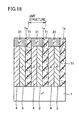
- a diode is formed in the cell portion.
- This diode includes a pn repeat structure having n type diffusion region 3 and p type diffusion region 4 in contact with each other to form a pn junction provided repeatedly, a p type well 31 formed on a first main surface side of the pn repeat structure, and an n + substrate region 1 located on a second main surface side of the pn repeat structure.
- Guard rings 61 are formed to surround a peripheral region of the cell portion five times, for example. Guard ring 61 has a breakdown voltage that is set lower than that of the cell portion.
- Setting of the breakdown voltage of guard ring 61 lower than that of the cell portion can be done in various ways, e.g., by narrowing a respective ring interval between guard rings 61.
- the breakdown voltage of the guard ring portion is set greater than that of the cell portion.
- ring intervals a, b, c, d and e between guard rings 61 are generally set to 5 ⁇ m, 7 ⁇ m, 9 ⁇ m, 11 ⁇ m and 13 ⁇ m, respectively, such that the breakdown voltage of the guard ring portion exceeds 300 V.
- any one of ring intervals a, b, c, d and e between guard rings 61 is reduced to approximately a half of the dimension described above. This can make the breakdown voltage of the guard ring portion smaller than 300 V, or, lower than the breakdown voltage of the cell portion.
- the breakdown voltage of guard rings 61 surrounding the periphery of the cell portion is set lower than that of the cell portion. Therefore, the peripheral portion of the cell portion experiences avalanche breakdown prior to the cell portion itself, and as a result, the avalanche breakdown tolerance of the device can be improved.
- guard rings 61 have been described above, the periphery of the cell portion may be surrounded by a field plate, as shown in Fig. 14. Specifically, electrode 62 electrically connected to p type well 31 may be extended to the periphery of the cell portion such that it is opposite to n - region 2 with an insulating layer 63 sandwiched therebetween, to constitute a field plate. The breakdown voltage of the field plate is set lower than that of the cell portion.
- the breakdown voltage of the field plate portion is determined according to a width "a" where electrode 62 is opposite to n - region 2.
- the breakdown voltage of the field plate is set greater than that of the cell portion.
- width "a" is set to the order of 10 ⁇ m such that the breakdown voltage of the field plate portion exceeds 100 V.
- the width "a" is narrowed to approximately a half (on the order of 5 ⁇ m). This makes the breakdown voltage of the field plate portion smaller than 100 V, or, lower than the breakdown voltage of the cell portion.
- the field plate surrounding the periphery of the cell portion is made to have a breakdown voltage lower than that of the cell portion.
- the peripheral portion will experience avalanche breakdown earlier than the cell portion.
- the avalanche breakdown tolerance of the device can be improved.
- the cell portion may have, as shown in Fig. 15, a configuration identical to that of the diode shown in Fig. 10 (the configuration where a set of n type and p type diffusion regions 3, 4 is sandwiched between trenches 1a).
- the cell portion may have, as shown in Fig. 16, a configuration of the STM shown in Fig. 1. Therefore, both in the diode having trenches (Fig. 15) and in the STM (Fig. 16), avalanche breakdown occurs in the peripheral portion of the cell portion before it occurs in the cell portion. As a result, avalanche breakdown tolerance of the device can be improved.
- a plurality of trenches 1a are formed at a first main surface of a semiconductor substrate 1.
- an n type diffusion region 3 and a p type diffusion region 4 are formed alternately.
- a p + impurity region 31 is formed on the first main surface side of n type diffusion region 3 and p type diffusion region 4.
- Trench 1a is filled with a charged layer 71 of insulative film or semi-insulative film charged with positive or negative charges.
- n + region of semiconductor substrate 1 is located on a second main surface side of n type diffusion region 3, p type diffusion region 4 and charged layer 71.
- n type and p type diffusion regions 3, 4 sandwiched between trenches 1a and charged layer 71 are regarded as a unit structure, a sum of an amount of positive charges and an amount of n type impurity within the unit structure is different from (or unbalanced with) a sum of an amount of negative charges and an amount of p type impurity within the same unit structure. That is, provision of charged layer 71 charged with positive or negative charges within the unit structure provides the same effect as in the case where the impurity amounts in n type diffusion region 3 and p type diffusion region 4 within a unit structure are made unbalanced with each other. Accordingly, it is possible to improve the avalanche breakdown tolerance as in the first embodiment.
- charged layer 71 is arranged in every gap between n type diffusion region 3 and p type diffusion region 4.
- charged layer 71 may be arranged in every gap between the neighboring pairs.
- n type and p type diffusion regions 3, 4 sandwiched between trenches 1a and charged layer 71 are regarded as a unit structure
- a sum of an amount of positive charges and an amount of n type impurity within the unit structure is different from (or unbalanced with) a sum of an amount of negative charges and an amount of p type impurity within the same unit structure. That is, provision of charged layer 71 charged with positive or negative charges in the unit structure provides the similar effect as in the case where the impurity amounts in n type and p type diffusion regions within the unit structure are made unbalanced.
- the semiconductor device of the present invention is advantageously applicable to the field where high breakdown voltage and high avalanche breakdown tolerance are required.
Landscapes
- Engineering & Computer Science (AREA)
- Microelectronics & Electronic Packaging (AREA)
- Power Engineering (AREA)
- Physics & Mathematics (AREA)
- Ceramic Engineering (AREA)
- Condensed Matter Physics & Semiconductors (AREA)
- General Physics & Mathematics (AREA)
- Computer Hardware Design (AREA)
- Chemical & Material Sciences (AREA)
- Composite Materials (AREA)
- Insulated Gate Type Field-Effect Transistor (AREA)
- Metal-Oxide And Bipolar Metal-Oxide Semiconductor Integrated Circuits (AREA)
Applications Claiming Priority (1)
| Application Number | Priority Date | Filing Date | Title |
|---|---|---|---|
| PCT/JP2002/000584 WO2003065459A1 (fr) | 2002-01-28 | 2002-01-28 | Dispositif a semi-conducteur |
Publications (1)
| Publication Number | Publication Date |
|---|---|
| EP1487021A1 true EP1487021A1 (en) | 2004-12-15 |
Family
ID=27639249
Family Applications (1)
| Application Number | Title | Priority Date | Filing Date |
|---|---|---|---|
| EP02716404A Withdrawn EP1487021A1 (en) | 2002-01-28 | 2002-01-28 | Semiconductor device |
Country Status (7)
| Country | Link |
|---|---|
| US (1) | US6949798B2 (zh) |
| EP (1) | EP1487021A1 (zh) |
| JP (1) | JPWO2003065459A1 (zh) |
| KR (1) | KR20030078867A (zh) |
| CN (1) | CN1237619C (zh) |
| TW (1) | TW552615B (zh) |
| WO (1) | WO2003065459A1 (zh) |
Families Citing this family (24)
| Publication number | Priority date | Publication date | Assignee | Title |
|---|---|---|---|---|
| JP3634830B2 (ja) * | 2002-09-25 | 2005-03-30 | 株式会社東芝 | 電力用半導体素子 |
| US7166890B2 (en) * | 2003-10-21 | 2007-01-23 | Srikant Sridevan | Superjunction device with improved ruggedness |
| US7041560B2 (en) * | 2003-12-19 | 2006-05-09 | Third Dimension (3D) Semiconductor, Inc. | Method of manufacturing a superjunction device with conventional terminations |
| JP4699692B2 (ja) * | 2003-12-26 | 2011-06-15 | ローム株式会社 | 半導体装置の製造方法および半導体装置 |
| US7812441B2 (en) | 2004-10-21 | 2010-10-12 | Siliconix Technology C.V. | Schottky diode with improved surge capability |
| TWI278090B (en) * | 2004-10-21 | 2007-04-01 | Int Rectifier Corp | Solderable top metal for SiC device |
| TWI401749B (zh) * | 2004-12-27 | 2013-07-11 | Third Dimension 3D Sc Inc | 用於高電壓超接面終止之方法 |
| US7834376B2 (en) | 2005-03-04 | 2010-11-16 | Siliconix Technology C. V. | Power semiconductor switch |
| US9419092B2 (en) * | 2005-03-04 | 2016-08-16 | Vishay-Siliconix | Termination for SiC trench devices |
| JP5303819B2 (ja) * | 2005-08-05 | 2013-10-02 | 住友電気工業株式会社 | 半導体装置およびその製造方法 |
| US8368165B2 (en) | 2005-10-20 | 2013-02-05 | Siliconix Technology C. V. | Silicon carbide Schottky diode |
| JP5225546B2 (ja) * | 2005-12-27 | 2013-07-03 | 株式会社豊田中央研究所 | 半導体装置 |
| US7659588B2 (en) * | 2006-01-26 | 2010-02-09 | Siliconix Technology C. V. | Termination for a superjunction device |
| WO2008016619A1 (en) * | 2006-07-31 | 2008-02-07 | Vishay-Siliconix | Molybdenum barrier metal for sic schottky diode and process of manufacture |
| CN101536164B (zh) * | 2006-09-27 | 2012-06-20 | 巨能半导体股份有限公司 | 具有凹陷场板的功率金属氧化物半导体场效应晶体管 |
| US8564057B1 (en) | 2007-01-09 | 2013-10-22 | Maxpower Semiconductor, Inc. | Power devices, structures, components, and methods using lateral drift, fixed net charge, and shield |
| US8659074B2 (en) * | 2007-01-09 | 2014-02-25 | Maxpower Semiconductor, Inc. | Semiconductor device |
| CN101345254A (zh) * | 2007-07-12 | 2009-01-14 | 富士电机电子技术株式会社 | 半导体器件 |
| WO2010065428A2 (en) * | 2008-12-01 | 2010-06-10 | Maxpower Semiconductor Inc. | Mos-gated power devices, methods, and integrated circuits |
| JP5537996B2 (ja) * | 2010-03-03 | 2014-07-02 | 株式会社東芝 | 半導体装置 |
| WO2015008550A1 (ja) * | 2013-07-19 | 2015-01-22 | 日産自動車株式会社 | 半導体装置及びその製造方法 |
| JP6275282B2 (ja) * | 2015-01-13 | 2018-02-07 | 三菱電機株式会社 | 半導体装置、その製造方法および半導体モジュール |
| JP6696329B2 (ja) * | 2016-07-05 | 2020-05-20 | 株式会社デンソー | 炭化珪素半導体装置およびその製造方法 |
| DE102018130444A1 (de) | 2018-11-30 | 2020-06-04 | Infineon Technologies Austria Ag | Verfahren zum Herstellen eines Superjunction-Transistorbauelements |
Family Cites Families (16)
| Publication number | Priority date | Publication date | Assignee | Title |
|---|---|---|---|---|
| US5506421A (en) * | 1992-11-24 | 1996-04-09 | Cree Research, Inc. | Power MOSFET in silicon carbide |
| JP3938964B2 (ja) * | 1997-02-10 | 2007-06-27 | 三菱電機株式会社 | 高耐圧半導体装置およびその製造方法 |
| US6081009A (en) | 1997-11-10 | 2000-06-27 | Intersil Corporation | High voltage mosfet structure |
| JP3382163B2 (ja) | 1998-10-07 | 2003-03-04 | 株式会社東芝 | 電力用半導体装置 |
| JP3799888B2 (ja) | 1998-11-12 | 2006-07-19 | 富士電機デバイステクノロジー株式会社 | 超接合半導体素子およびその製造方法 |
| US6291856B1 (en) * | 1998-11-12 | 2001-09-18 | Fuji Electric Co., Ltd. | Semiconductor device with alternating conductivity type layer and method of manufacturing the same |
| JP3751463B2 (ja) | 1999-03-23 | 2006-03-01 | 株式会社東芝 | 高耐圧半導体素子 |
| JP2000286417A (ja) | 1999-03-30 | 2000-10-13 | Toshiba Corp | 電力用半導体装置 |
| GB9917099D0 (en) * | 1999-07-22 | 1999-09-22 | Koninkl Philips Electronics Nv | Cellular trench-gate field-effect transistors |
| JP3507732B2 (ja) | 1999-09-30 | 2004-03-15 | 株式会社東芝 | 半導体装置 |
| JP2001119022A (ja) | 1999-10-20 | 2001-04-27 | Fuji Electric Co Ltd | 半導体装置及びその製造方法 |
| JP4450122B2 (ja) * | 1999-11-17 | 2010-04-14 | 株式会社デンソー | 炭化珪素半導体装置 |
| JP2001168036A (ja) | 1999-12-09 | 2001-06-22 | Fuji Electric Co Ltd | 半導体素子の製造方法 |
| JP4240752B2 (ja) * | 2000-05-01 | 2009-03-18 | 富士電機デバイステクノロジー株式会社 | 半導体装置 |
| JP4285899B2 (ja) * | 2000-10-10 | 2009-06-24 | 三菱電機株式会社 | 溝を有する半導体装置 |
| US20030030051A1 (en) * | 2001-08-09 | 2003-02-13 | International Rectifier Corporation | Superjunction device with improved avalanche capability and breakdown voltage |
-
2002
- 2002-01-28 EP EP02716404A patent/EP1487021A1/en not_active Withdrawn
- 2002-01-28 CN CNB028031954A patent/CN1237619C/zh not_active Expired - Fee Related
- 2002-01-28 US US10/416,287 patent/US6949798B2/en not_active Expired - Fee Related
- 2002-01-28 KR KR10-2003-7006832A patent/KR20030078867A/ko not_active Application Discontinuation
- 2002-01-28 WO PCT/JP2002/000584 patent/WO2003065459A1/ja not_active Application Discontinuation
- 2002-01-28 JP JP2003564942A patent/JPWO2003065459A1/ja not_active Withdrawn
- 2002-03-05 TW TW091103999A patent/TW552615B/zh not_active IP Right Cessation
Non-Patent Citations (1)
| Title |
|---|
| See references of WO03065459A1 * |
Also Published As
| Publication number | Publication date |
|---|---|
| KR20030078867A (ko) | 2003-10-08 |
| TW552615B (en) | 2003-09-11 |
| US20040150040A1 (en) | 2004-08-05 |
| CN1237619C (zh) | 2006-01-18 |
| CN1488172A (zh) | 2004-04-07 |
| WO2003065459A1 (fr) | 2003-08-07 |
| US6949798B2 (en) | 2005-09-27 |
| JPWO2003065459A1 (ja) | 2005-05-26 |
Similar Documents
| Publication | Publication Date | Title |
|---|---|---|
| US6949798B2 (en) | Semiconductor device | |
| US10084037B2 (en) | MOSFET active area and edge termination area charge balance | |
| US8227854B2 (en) | Semiconductor device having first and second resurf layers | |
| US7317213B2 (en) | Semiconductor device having super junction structure and method for manufacturing the same | |
| EP2043158B1 (en) | Trench DMOS transistor with trench bottom implant | |
| US7948033B2 (en) | Semiconductor device having trench edge termination structure | |
| US8304312B2 (en) | Charged balanced devices with shielded gate trench | |
| US6184555B1 (en) | Field effect-controlled semiconductor component | |
| US6512267B2 (en) | Superjunction device with self compensated trench walls | |
| US6979862B2 (en) | Trench MOSFET superjunction structure and method to manufacture | |
| US8860130B2 (en) | Charged balanced devices with shielded gate trench | |
| EP1267415A2 (en) | Power semiconductor device having resurf layer | |
| WO2003034470A2 (en) | Semiconductor structure with improved smaller forward voltage loss and higher blocking capability | |
| US11322607B2 (en) | Semiconductor device | |
| US20150372131A1 (en) | Charged balanced devices with shielded gate trench | |
| WO2003005414A2 (en) | Power mosfet with deep implanted junctions | |
| US8704302B2 (en) | Power semiconductor devices and methods | |
| US7538388B2 (en) | Semiconductor device with a super-junction | |
| EP0961325A1 (en) | High integration density MOS technology power device structure | |
| CN111463131A (zh) | 超结半导体器件及其制造方法 | |
| KR101361067B1 (ko) | 수퍼 정션 금속 산화물 반도체 전계 효과 트랜지스터의 제조 방법 | |
| US20230246102A1 (en) | Superjunction semiconductor device | |
| US20240321953A1 (en) | Superjunction transistor device | |
| CN111816694A (zh) | 超结半导体装置及超结半导体装置的制造方法 |
Legal Events
| Date | Code | Title | Description |
|---|---|---|---|
| PUAI | Public reference made under article 153(3) epc to a published international application that has entered the european phase |
Free format text: ORIGINAL CODE: 0009012 |
|
| 17P | Request for examination filed |
Effective date: 20030523 |
|
| AK | Designated contracting states |
Kind code of ref document: A1 Designated state(s): AT BE CH CY DE DK ES FI FR GB GR IE IT LI LU MC NL PT SE TR |
|
| STAA | Information on the status of an ep patent application or granted ep patent |
Free format text: STATUS: THE APPLICATION HAS BEEN WITHDRAWN |
|
| 18W | Application withdrawn |
Effective date: 20060113 |