US10084037B2 - MOSFET active area and edge termination area charge balance - Google Patents
MOSFET active area and edge termination area charge balance Download PDFInfo
- Publication number
- US10084037B2 US10084037B2 US15/339,678 US201615339678A US10084037B2 US 10084037 B2 US10084037 B2 US 10084037B2 US 201615339678 A US201615339678 A US 201615339678A US 10084037 B2 US10084037 B2 US 10084037B2
- Authority
- US
- United States
- Prior art keywords
- trenches
- edge termination
- active area
- implants
- area
- Prior art date
- Legal status (The legal status is an assumption and is not a legal conclusion. Google has not performed a legal analysis and makes no representation as to the accuracy of the status listed.)
- Active
Links
- 239000007943 implant Substances 0.000 claims abstract description 111
- 238000000034 method Methods 0.000 claims abstract description 22
- BHEPBYXIRTUNPN-UHFFFAOYSA-N hydridophosphorus(.) (triplet) Chemical compound [PH] BHEPBYXIRTUNPN-UHFFFAOYSA-N 0.000 claims description 5
- 239000004065 semiconductor Substances 0.000 claims description 5
- ZOXJGFHDIHLPTG-UHFFFAOYSA-N Boron Chemical compound [B] ZOXJGFHDIHLPTG-UHFFFAOYSA-N 0.000 claims 3
- 229910052796 boron Inorganic materials 0.000 claims 3
- 239000002184 metal Substances 0.000 claims 2
- 230000015556 catabolic process Effects 0.000 abstract description 16
- 238000002513 implantation Methods 0.000 description 10
- 239000000758 substrate Substances 0.000 description 6
- 229910021420 polycrystalline silicon Inorganic materials 0.000 description 5
- 229920005591 polysilicon Polymers 0.000 description 5
- VYPSYNLAJGMNEJ-UHFFFAOYSA-N Silicium dioxide Chemical compound O=[Si]=O VYPSYNLAJGMNEJ-UHFFFAOYSA-N 0.000 description 4
- 239000005380 borophosphosilicate glass Substances 0.000 description 4
- 238000000151 deposition Methods 0.000 description 4
- 230000008021 deposition Effects 0.000 description 4
- 230000005684 electric field Effects 0.000 description 4
- 239000000126 substance Substances 0.000 description 4
- 230000008901 benefit Effects 0.000 description 3
- 230000005669 field effect Effects 0.000 description 3
- 238000002161 passivation Methods 0.000 description 3
- 229920002120 photoresistant polymer Polymers 0.000 description 3
- 239000002800 charge carrier Substances 0.000 description 2
- 229910052681 coesite Inorganic materials 0.000 description 2
- 229910052906 cristobalite Inorganic materials 0.000 description 2
- 239000012535 impurity Substances 0.000 description 2
- 230000000873 masking effect Effects 0.000 description 2
- 229910044991 metal oxide Inorganic materials 0.000 description 2
- 150000004706 metal oxides Chemical class 0.000 description 2
- 238000001465 metallisation Methods 0.000 description 2
- 238000001020 plasma etching Methods 0.000 description 2
- 239000000377 silicon dioxide Substances 0.000 description 2
- 235000012239 silicon dioxide Nutrition 0.000 description 2
- 229910052682 stishovite Inorganic materials 0.000 description 2
- 229910052905 tridymite Inorganic materials 0.000 description 2
- 230000015572 biosynthetic process Effects 0.000 description 1
- 230000000903 blocking effect Effects 0.000 description 1
- 239000000969 carrier Substances 0.000 description 1
- 230000007423 decrease Effects 0.000 description 1
- 239000012212 insulator Substances 0.000 description 1
- 238000005457 optimization Methods 0.000 description 1
- 238000005498 polishing Methods 0.000 description 1
Images


Classifications
-
- H—ELECTRICITY
- H01—ELECTRIC ELEMENTS
- H01L—SEMICONDUCTOR DEVICES NOT COVERED BY CLASS H10
- H01L29/00—Semiconductor devices adapted for rectifying, amplifying, oscillating or switching, or capacitors or resistors with at least one potential-jump barrier or surface barrier, e.g. PN junction depletion layer or carrier concentration layer; Details of semiconductor bodies or of electrodes thereof ; Multistep manufacturing processes therefor
- H01L29/66—Types of semiconductor device ; Multistep manufacturing processes therefor
- H01L29/66007—Multistep manufacturing processes
- H01L29/66075—Multistep manufacturing processes of devices having semiconductor bodies comprising group 14 or group 13/15 materials
- H01L29/66227—Multistep manufacturing processes of devices having semiconductor bodies comprising group 14 or group 13/15 materials the devices being controllable only by the electric current supplied or the electric potential applied, to an electrode which does not carry the current to be rectified, amplified or switched, e.g. three-terminal devices
- H01L29/66409—Unipolar field-effect transistors
- H01L29/66477—Unipolar field-effect transistors with an insulated gate, i.e. MISFET
- H01L29/66674—DMOS transistors, i.e. MISFETs with a channel accommodating body or base region adjoining a drain drift region
- H01L29/66712—Vertical DMOS transistors, i.e. VDMOS transistors
- H01L29/66734—Vertical DMOS transistors, i.e. VDMOS transistors with a step of recessing the gate electrode, e.g. to form a trench gate electrode
-
- H—ELECTRICITY
- H01—ELECTRIC ELEMENTS
- H01L—SEMICONDUCTOR DEVICES NOT COVERED BY CLASS H10
- H01L29/00—Semiconductor devices adapted for rectifying, amplifying, oscillating or switching, or capacitors or resistors with at least one potential-jump barrier or surface barrier, e.g. PN junction depletion layer or carrier concentration layer; Details of semiconductor bodies or of electrodes thereof ; Multistep manufacturing processes therefor
- H01L29/02—Semiconductor bodies ; Multistep manufacturing processes therefor
- H01L29/06—Semiconductor bodies ; Multistep manufacturing processes therefor characterised by their shape; characterised by the shapes, relative sizes, or dispositions of the semiconductor regions ; characterised by the concentration or distribution of impurities within semiconductor regions
- H01L29/0603—Semiconductor bodies ; Multistep manufacturing processes therefor characterised by their shape; characterised by the shapes, relative sizes, or dispositions of the semiconductor regions ; characterised by the concentration or distribution of impurities within semiconductor regions characterised by particular constructional design considerations, e.g. for preventing surface leakage, for controlling electric field concentration or for internal isolations regions
- H01L29/0607—Semiconductor bodies ; Multistep manufacturing processes therefor characterised by their shape; characterised by the shapes, relative sizes, or dispositions of the semiconductor regions ; characterised by the concentration or distribution of impurities within semiconductor regions characterised by particular constructional design considerations, e.g. for preventing surface leakage, for controlling electric field concentration or for internal isolations regions for preventing surface leakage or controlling electric field concentration
- H01L29/0611—Semiconductor bodies ; Multistep manufacturing processes therefor characterised by their shape; characterised by the shapes, relative sizes, or dispositions of the semiconductor regions ; characterised by the concentration or distribution of impurities within semiconductor regions characterised by particular constructional design considerations, e.g. for preventing surface leakage, for controlling electric field concentration or for internal isolations regions for preventing surface leakage or controlling electric field concentration for increasing or controlling the breakdown voltage of reverse biased devices
- H01L29/0615—Semiconductor bodies ; Multistep manufacturing processes therefor characterised by their shape; characterised by the shapes, relative sizes, or dispositions of the semiconductor regions ; characterised by the concentration or distribution of impurities within semiconductor regions characterised by particular constructional design considerations, e.g. for preventing surface leakage, for controlling electric field concentration or for internal isolations regions for preventing surface leakage or controlling electric field concentration for increasing or controlling the breakdown voltage of reverse biased devices by the doping profile or the shape or the arrangement of the PN junction, or with supplementary regions, e.g. junction termination extension [JTE]
- H01L29/063—Reduced surface field [RESURF] pn-junction structures
- H01L29/0634—Multiple reduced surface field (multi-RESURF) structures, e.g. double RESURF, charge compensation, cool, superjunction (SJ), 3D-RESURF, composite buffer (CB) structures
-
- H—ELECTRICITY
- H01—ELECTRIC ELEMENTS
- H01L—SEMICONDUCTOR DEVICES NOT COVERED BY CLASS H10
- H01L29/00—Semiconductor devices adapted for rectifying, amplifying, oscillating or switching, or capacitors or resistors with at least one potential-jump barrier or surface barrier, e.g. PN junction depletion layer or carrier concentration layer; Details of semiconductor bodies or of electrodes thereof ; Multistep manufacturing processes therefor
- H01L29/02—Semiconductor bodies ; Multistep manufacturing processes therefor
- H01L29/06—Semiconductor bodies ; Multistep manufacturing processes therefor characterised by their shape; characterised by the shapes, relative sizes, or dispositions of the semiconductor regions ; characterised by the concentration or distribution of impurities within semiconductor regions
- H01L29/08—Semiconductor bodies ; Multistep manufacturing processes therefor characterised by their shape; characterised by the shapes, relative sizes, or dispositions of the semiconductor regions ; characterised by the concentration or distribution of impurities within semiconductor regions with semiconductor regions connected to an electrode carrying current to be rectified, amplified or switched and such electrode being part of a semiconductor device which comprises three or more electrodes
- H01L29/0843—Source or drain regions of field-effect devices
- H01L29/0847—Source or drain regions of field-effect devices of field-effect transistors with insulated gate
- H01L29/0852—Source or drain regions of field-effect devices of field-effect transistors with insulated gate of DMOS transistors
- H01L29/0873—Drain regions
- H01L29/0878—Impurity concentration or distribution
-
- H—ELECTRICITY
- H01—ELECTRIC ELEMENTS
- H01L—SEMICONDUCTOR DEVICES NOT COVERED BY CLASS H10
- H01L29/00—Semiconductor devices adapted for rectifying, amplifying, oscillating or switching, or capacitors or resistors with at least one potential-jump barrier or surface barrier, e.g. PN junction depletion layer or carrier concentration layer; Details of semiconductor bodies or of electrodes thereof ; Multistep manufacturing processes therefor
- H01L29/02—Semiconductor bodies ; Multistep manufacturing processes therefor
- H01L29/06—Semiconductor bodies ; Multistep manufacturing processes therefor characterised by their shape; characterised by the shapes, relative sizes, or dispositions of the semiconductor regions ; characterised by the concentration or distribution of impurities within semiconductor regions
- H01L29/10—Semiconductor bodies ; Multistep manufacturing processes therefor characterised by their shape; characterised by the shapes, relative sizes, or dispositions of the semiconductor regions ; characterised by the concentration or distribution of impurities within semiconductor regions with semiconductor regions connected to an electrode not carrying current to be rectified, amplified or switched and such electrode being part of a semiconductor device which comprises three or more electrodes
- H01L29/1095—Body region, i.e. base region, of DMOS transistors or IGBTs
-
- H—ELECTRICITY
- H01—ELECTRIC ELEMENTS
- H01L—SEMICONDUCTOR DEVICES NOT COVERED BY CLASS H10
- H01L29/00—Semiconductor devices adapted for rectifying, amplifying, oscillating or switching, or capacitors or resistors with at least one potential-jump barrier or surface barrier, e.g. PN junction depletion layer or carrier concentration layer; Details of semiconductor bodies or of electrodes thereof ; Multistep manufacturing processes therefor
- H01L29/02—Semiconductor bodies ; Multistep manufacturing processes therefor
- H01L29/12—Semiconductor bodies ; Multistep manufacturing processes therefor characterised by the materials of which they are formed
- H01L29/16—Semiconductor bodies ; Multistep manufacturing processes therefor characterised by the materials of which they are formed including, apart from doping materials or other impurities, only elements of Group IV of the Periodic System
- H01L29/167—Semiconductor bodies ; Multistep manufacturing processes therefor characterised by the materials of which they are formed including, apart from doping materials or other impurities, only elements of Group IV of the Periodic System further characterised by the doping material
-
- H—ELECTRICITY
- H01—ELECTRIC ELEMENTS
- H01L—SEMICONDUCTOR DEVICES NOT COVERED BY CLASS H10
- H01L29/00—Semiconductor devices adapted for rectifying, amplifying, oscillating or switching, or capacitors or resistors with at least one potential-jump barrier or surface barrier, e.g. PN junction depletion layer or carrier concentration layer; Details of semiconductor bodies or of electrodes thereof ; Multistep manufacturing processes therefor
- H01L29/40—Electrodes ; Multistep manufacturing processes therefor
- H01L29/402—Field plates
- H01L29/407—Recessed field plates, e.g. trench field plates, buried field plates
-
- H—ELECTRICITY
- H01—ELECTRIC ELEMENTS
- H01L—SEMICONDUCTOR DEVICES NOT COVERED BY CLASS H10
- H01L29/00—Semiconductor devices adapted for rectifying, amplifying, oscillating or switching, or capacitors or resistors with at least one potential-jump barrier or surface barrier, e.g. PN junction depletion layer or carrier concentration layer; Details of semiconductor bodies or of electrodes thereof ; Multistep manufacturing processes therefor
- H01L29/40—Electrodes ; Multistep manufacturing processes therefor
- H01L29/408—Electrodes ; Multistep manufacturing processes therefor with an insulating layer with a particular dielectric or electrostatic property, e.g. with static charges or for controlling trapped charges or moving ions, or with a plate acting on the insulator potential or the insulator charges, e.g. for controlling charges effect or potential distribution in the insulating layer, or with a semi-insulating layer contacting directly the semiconductor surface
-
- H—ELECTRICITY
- H01—ELECTRIC ELEMENTS
- H01L—SEMICONDUCTOR DEVICES NOT COVERED BY CLASS H10
- H01L29/00—Semiconductor devices adapted for rectifying, amplifying, oscillating or switching, or capacitors or resistors with at least one potential-jump barrier or surface barrier, e.g. PN junction depletion layer or carrier concentration layer; Details of semiconductor bodies or of electrodes thereof ; Multistep manufacturing processes therefor
- H01L29/66—Types of semiconductor device ; Multistep manufacturing processes therefor
- H01L29/68—Types of semiconductor device ; Multistep manufacturing processes therefor controllable by only the electric current supplied, or only the electric potential applied, to an electrode which does not carry the current to be rectified, amplified or switched
- H01L29/76—Unipolar devices, e.g. field effect transistors
- H01L29/772—Field effect transistors
- H01L29/78—Field effect transistors with field effect produced by an insulated gate
- H01L29/7801—DMOS transistors, i.e. MISFETs with a channel accommodating body or base region adjoining a drain drift region
- H01L29/7802—Vertical DMOS transistors, i.e. VDMOS transistors
- H01L29/7811—Vertical DMOS transistors, i.e. VDMOS transistors with an edge termination structure
-
- H—ELECTRICITY
- H01—ELECTRIC ELEMENTS
- H01L—SEMICONDUCTOR DEVICES NOT COVERED BY CLASS H10
- H01L29/00—Semiconductor devices adapted for rectifying, amplifying, oscillating or switching, or capacitors or resistors with at least one potential-jump barrier or surface barrier, e.g. PN junction depletion layer or carrier concentration layer; Details of semiconductor bodies or of electrodes thereof ; Multistep manufacturing processes therefor
- H01L29/66—Types of semiconductor device ; Multistep manufacturing processes therefor
- H01L29/68—Types of semiconductor device ; Multistep manufacturing processes therefor controllable by only the electric current supplied, or only the electric potential applied, to an electrode which does not carry the current to be rectified, amplified or switched
- H01L29/76—Unipolar devices, e.g. field effect transistors
- H01L29/772—Field effect transistors
- H01L29/78—Field effect transistors with field effect produced by an insulated gate
- H01L29/7801—DMOS transistors, i.e. MISFETs with a channel accommodating body or base region adjoining a drain drift region
- H01L29/7802—Vertical DMOS transistors, i.e. VDMOS transistors
- H01L29/7813—Vertical DMOS transistors, i.e. VDMOS transistors with trench gate electrode, e.g. UMOS transistors
-
- H—ELECTRICITY
- H01—ELECTRIC ELEMENTS
- H01L—SEMICONDUCTOR DEVICES NOT COVERED BY CLASS H10
- H01L29/00—Semiconductor devices adapted for rectifying, amplifying, oscillating or switching, or capacitors or resistors with at least one potential-jump barrier or surface barrier, e.g. PN junction depletion layer or carrier concentration layer; Details of semiconductor bodies or of electrodes thereof ; Multistep manufacturing processes therefor
- H01L29/66—Types of semiconductor device ; Multistep manufacturing processes therefor
- H01L29/68—Types of semiconductor device ; Multistep manufacturing processes therefor controllable by only the electric current supplied, or only the electric potential applied, to an electrode which does not carry the current to be rectified, amplified or switched
- H01L29/76—Unipolar devices, e.g. field effect transistors
- H01L29/772—Field effect transistors
- H01L29/78—Field effect transistors with field effect produced by an insulated gate
- H01L29/7801—DMOS transistors, i.e. MISFETs with a channel accommodating body or base region adjoining a drain drift region
- H01L29/7816—Lateral DMOS transistors, i.e. LDMOS transistors
- H01L29/7823—Lateral DMOS transistors, i.e. LDMOS transistors with an edge termination structure
Definitions
- the present invention relates to MOSFET active area and edge termination area charge balance.
- MOSFET metal-oxide semiconductor field-effect transistor
- MOSFETs include gate, drain and source components. Charge carriers enter the channel via the source, and exit via the drain. The width of the MOSFET channel can be controlled by varying the voltage that is placed onto a gate electrode. In conventional MOSFETs the gate electrode is generally insulated from the channel by a thin layer of oxide.
- MOSFET operational parameters affect the operation and performance of the MOSFET.
- MOSFET operational parameters include drain-source breakdown voltage (BVds) and drain-source on resistance (RDSon).
- the MOSFET BVds is the minimum voltage that causes a portion of an insulator to become electrically conductive. Thus, generally a high BVds is desirable. Importantly, when the BVds is exceeded, current flow can occur which can prevent the MOSFET from shutting off properly.
- RDSon is the drain-source resistance at a specified drain current and gate-source voltage. In many applications a low RDSon is desirable and is associated with an increased MOSFET current carrying capability.
- FIG. 1A shows a conventional MOSFET that includes active 101 and edge termination 103 areas.
- the desired direction of current flow is vertical through the MOSFET (see dotted line representing the vertical channel 105 next to active area trench 107 ).
- BVds if BVds is exceeded, then breakdown can occur in the oxide that lines the corners of device trenches, and undesirable current flow can occur in the MOSFET. This is because many conventional MOSFETs exhibit uneven electric fields where the strength of the electric field can be greatest at corners of MOSFET trenches.
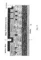
- FIG. 1B shows trench locations 111 , 113 and 115 that are vulnerable to breakdown in the oxide that lines the walls of the edge termination area trenches 109 of the conventional MOSFET shown in FIG. 1A .
- such current flow can prevent a MOSFET from shutting off properly.
- many conventional MOSFETs are provided with inadequate protection against edge termination area voltage breakdown and are susceptible to such current flow.
- the present invention provides a method that accomplishes this need.
- Embodiments of the present invention enable the optimization of breakdown voltage (BVds) in both the active and edge termination areas of a MOSFET by making tuned implants at trench bottoms in both areas that result in a charge balanced implant region.
- the charge balance results in a flat electric field across the implant region that supports higher breakdown voltages (BVds).
- the higher doping concentration that results from implants made in the active region advantageously lowers device on resistance (RDSon) of the MOSFET.
- a first plurality of implants are formed at the bottom of trenches located in an active area and in an edge termination area of a MOSFET. Subsequently, a second plurality of implants is formed at the bottom of the trenches located in the active area only. The second plurality of implants formed at the bottom of the trenches located in the active area of the MOSFET causes the implants formed at the bottom of the trenches located in the active area to reach a desired concentration.
- a disclosed method for fabricating a MOSFET having an active area and an edge termination area includes forming first and second epitaxial layers on a substrate, forming trenches in the active area and in the edge termination area in the topmost of the epitaxial layers, and forming multiple implants at the bottom of the trenches formed in the active area and in the edge termination area. Moreover, the method includes masking the edge termination area, forming multiple implants at the bottom of the trenches formed in the active area and forming a thick oxide layer on the edge termination area. A layer of oxide formed in the trenches located in the edge termination area is thicker than a layer of oxide formed in the trenches located in the active area.
- a MOSFET that includes an active area and an edge termination area with both areas having similar BVds.
- the active area includes a plurality of active area trenches, a source region adjacent one or more sidewalls of the plurality of trenches, a gate region located adjacent to and vertically underneath the source region, and a drain region located adjacent to and vertically underneath the gate region.
- the edge termination area includes a gate pickup trench and a plurality of termination trenches. A first plurality of implants is provided at the bottom of the trenches located in both the active area and the edge termination area.
- a second plurality of implants are formed at the bottom of the trenches located in the active area and causes the implants formed at the bottom of the trenches located in the active area to reach a predetermined desired concentration.
- the MOSFET may advantageously have optimized BVds in both the active and edge termination areas.
- FIG. 1A shows a conventional metal oxide semiconductor field effect transistor (MOSFET) device that includes active and edge termination areas.
- MOSFET metal oxide semiconductor field effect transistor
- FIG. 1B shows vulnerable locations in the oxide that lines the walls of edge termination area trenches of the conventional MOSFET shown in FIG. 1B .
- FIG. 2A shows a cross section of a MOSFET formed according to one embodiment of the invention.
- FIG. 2B illustrates tuning operations of an implantation process for achieving charge balance between active and edge termination areas according to one embodiment of the present invention.
- FIG. 3A shows an N epi-layer and a P epi-layer formed on an N+ substrate according to one embodiment of the present invention.
- FIG. 3B shows active area and edge termination area trenches formed in a P epi-layer according to one embodiment of the present invention.
- FIG. 3C shows first N-type multiple implants made at the bottom of active area and edge termination area trenches according to one embodiment of the present invention.
- FIG. 3D shows second N-type multiple implants made at the bottom of active area trenches according to one embodiment of the present invention.
- FIG. 3E shows a thick oxide layer grown on a termination trench area that is formed using a mask and a gate oxide layer grown on active area according to one embodiment of the present invention.
- FIG. 3F shows a deposition of polysilicon formed in active area and edge termination area trenches according to one embodiment of the present invention.
- FIG. 3G shows a threshold voltage (Vt) adjustment implant and a source implant according to one embodiment of the present invention.
- FIG. 3H shows a device cross section after low thermal oxide (LTO) and borophosphosilicate glass (BPSG) deposition according to one embodiment of the present invention.
- LTO low thermal oxide
- BPSG borophosphosilicate glass
- FIG. 3I shows a device cross section after contact implants and metallization and passivation layers are formed according to one embodiment of the present invention.
- FIG. 2A shows a cross section of a MOSFET 200 formed according to one embodiment of the invention.
- multiple implants are made to MOSFET 200 active area 200 a and edge termination area 200 b trench bottoms to achieve charge balance between these areas.
- this charge balance provides MOSFET 200 with breakdown voltages (BVds) that are similar in each area and moreover, the BVds may be optimized in both areas.
- BVds breakdown voltages
- the higher doping concentration provided by the implants results in lowered MOSFET 200 on-resistance (RDSon).
- the charge balance causes the electric field across the implant region to be flat which supports an attainment of a higher BVds for MOSFET 200 as compared with MOSFETs that do not feature a charge balanced implant region.
- MOSFET 200 includes substrate 201 , epitaxial (epi) layer 203 , epitaxial (epi) layer 205 , multiple active area implants 207 , multiple edge termination area implants 209 , source implants 211 , P body well 213 , gate region 215 , drain region 217 , active area trench 219 , active area trench 221 , gate pickup trench 223 , edge termination area trenches 225 a - 225 c , oxide layer 227 , active area trench oxide 229 , edge termination area trench oxide 231 , gate poly 233 , source electrode 235 , gate electrode 237 , drain electrode 239 , passivation layer 241 and scribeline 243 .
- multiple implants 207 and 209 are formed at the bottom of active area 200 a and edge termination area 200 b trenches 219 , 221 , 223 and 225 a - 225 c in accordance with processes described herein (see discussion made with reference to FIGS. 3A-3H ).
- the implants made at the bottom of active area trenches 219 and 221 form portions of the drain region of MOSFET 200 .
- the formation of these implants can be completed in two implantation operations. Initially, multiple implants are formed at the bottom of both active area trenches 219 and 221 and edge termination area trenches 223 and 225 a - 225 c . Thereafter, second multiple implants are made at the bottom of active area trenches 219 and 221 .
- the second multiple implants made at the bottom of active area trenches 219 and 221 are added to the first multiple implants that are made at the bottom of active area trenches 219 and 221 in the first implantation operation.
- the second multiple implants are used to advantageously “tune” or adjust the implants that are made at the bottom of active area trenches 219 and 221 , in the first multiple implant operation, to a desired doping concentration.
- the implants are tuned to achieve a charge balance between the active area 200 a and the edge termination area 200 b of device 200 .
- the charge balance thus achieved between the active area 200 a and the edge termination area 200 b supports a higher BVds. In this manner, the BVds can be optimized in both areas 200 a and 200 b.
- FIG. 2B illustrates tuning operations of an implantation process for achieving the aforementioned charge balance according to one embodiment of the present invention.
- the doping concentration of implants located at the bottom of the trenches reach a level that is optimal for edge termination area trenches 223 and 225 a - 225 c .
- the second plurality of implants serve to “tune” the doping concentration of implants located at the bottom of active area trenches 219 and 221 to a concentration that is optimal for the active area trenches while leaving alone the trenches of the termination area.
- implantation energies used to make the implants can be selected to achieve the desired doping concentration for the implants.
- implantation energies can include but are not limited to 150, 350 and 450 ev in one example. In other embodiments, other implantation energies can be employed.
- MOSFET 200 is provided with an edge termination structure that includes edge termination trenches 225 a - 225 c .
- this structure is provided in order to prevent voltage breakdown or current leakage via paths created when the MOSFET 200 die is cut at scribeline 243 .
- the plurality of trenches 225 a - 225 c that are a part of the edge termination structure distribute or step down the source to drain voltage which lessens the risk of voltage breakdown.
- edge termination trench oxide 231 is formed to have a greater thickness than the thickness of active area trench oxide 229 .
- the thickness of edge termination area trench oxide 231 enables the support of larger reverse bias voltages in the off-state than could be supported by a less thick oxide layer.
- a 1.5 kilo angstrom thickness can be employed in forming this layer of oxide. In other embodiments, other thicknesses can be employed. This thick oxide layer, by enabling the support of larger reverse bias voltages, provides protection against voltage breakdown.
- the high doping concentration provided by multiple implants reduces electrical resistance for electron flow and thus lowers RDSon.
- the charge balanced active and edge termination areas, 200 a and 200 b that are provided by the multiple implants allow a full depletion of charge from the implant region in the off state, which supports high voltage conditions during off state.
- the higher doping of the MOSFET drift region provided by multiple active area implants 207 allows easier flow of carriers thereby advantageously reducing RDSon.
- the tuned implantation approach of the present invention allows the implants made to be tuned to a precise doping concentration needed for trenches of the particular widths used. It is appreciated that in this manner charge balance can be achieved despite the presence of trenches of different widths in the device. Moreover, in one embodiment, vertical current flow is maintained in active area 200 a while undesirable current flow and voltage breakdown in edge termination area 200 b is avoided.
- MOSFET 200 can be made with P epi layer/N epi layer/N+ substrate for N-channel devices and N epi layer/P epi layer/P+ substrate for P-channel devices.
- MOSFET 200 multiple implants 207 and 209 are made at levels that are optimal for a desired BVds through trench bottoms to achieve charge balance over the entire implant region of the device as is discussed above.
- separate multiple implants between active area 200 a trench bottom and edge termination 200 b trench bottom provide optimized BVds on both areas.
- FIGS. 3A-3I show a series of cross sections illustrating an exemplary process for providing MOSFET active area and edge termination area charge balance using multiple implants according to one embodiment of the invention. Structures similar to those shown in FIG. 2A are similarly labeled in FIGS. 3A-3I .
- N epi-layer 203 and P epi-layer 205 are formed on N+ substrate 201 .
- active area and edge termination area trenches 219 , 221 , 223 and 225 a - 225 c are formed in P epi-layer 205 .
- a hard mask 301 is used to define the locations of the trenches.
- hard mask 301 can be formed from low thermal oxide, LTO, SiO2. In other embodiments, other substances can be used to form hard mask 301 .
- the locations of the openings in hard mask 301 that define the locations of active area 200 a and edge termination area 200 b trenches can be defined using photoresist (not shown).
- the trenches are formed by a plasma etching process. In another embodiment, other processes can be used. The thickness of the trench can be controlled by the amount of implant energy used when plasma etching is employed.
- an oxide layer 303 is formed on the bottom and sidewalls of the trenches.
- oxide layer 303 formed on the bottom and sidewalls of the trenches may be formed from SiO2.
- the oxide may be formed using low thermal oxide (LTO) processes.
- first N-type multiple implant operation 305 is used to make first N-type multiple implants at the bottom of active area and edge termination area trenches (e.g., 207 and 209 ).
- the implants may be provided in a blanket manner parallel to the device surface, hard mask 301 (by selectively blocking the implants) ensures that the implants are implanted in desired locations at the bottom of the trenches (e.g., 207 and 209 ).
- first N-type multiple implant operation 305 may use phosphorous implants. In other embodiments, other substances may be used.
- the implant energy that is used to make the implants at the bottom of the trenches depends on the desired breakdown voltage. Moreover, the dosage of the implants depends on the width of the associated trench. In one embodiment, for an 8K angstrom hard mask implant energies can include but are not limited to 150, 350 and 450 ev, for instance.
- second N-type multiple implants operation 307 is used to make second N-type multiple implants at the bottom of active area trenches (e.g., 207 ).
- the second N-type multiple implants are used to tune the implants already made at the bottom of active area trenches 219 and 221 to a desired concentration.
- a photoresist mask 309 can be used to cover edge termination area 200 b before the implantation of second N-type multiple implants 307 , such that second N-type multiple implants 307 are prevented from implantation at the bottom of edge termination area trenches 223 , 225 a , 225 b and 225 c.
- second N-type multiple implant operation 307 can use phosphorous implants. In other embodiments, other substances may be used in second N-type multiple implant operation 307 .
- a photoresist mask 309 can be formed to cover each of the trenches except active area trenches 219 and 221 .
- the implant energy may depend on the desired breakdown voltage and the dosage may depend on trench width.
- thick oxide 311 is grown on edge termination trench area using a mask (not shown) and a gate oxide 313 is grown on active area.
- this may be accomplished by: (1) growing a thick oxide layer on the entire surface of the device and in trenches, (2) masking the surface of the device and trenches in the edge termination region and then removing the thick oxide layer from the remainder of the surface and trenches, and (3) thereafter reapplying a thin oxide layer on the remainder of the surface and trenches.
- other techniques for forming thick 311 and thin oxide 313 layers can be used.
- thick oxide layer 311 can be grown to a 1.5 Kilo-angstrom thickness. In other embodiments, thick oxide layer 311 can be grown to other thicknesses. In one embodiment, thin oxide layer 313 can be grown to a 100 angstrom thickness. In other embodiments, thin oxide layer 313 can be grown to other thicknesses.
- a deposition of polysilicon 315 into active area 200 a and edge termination area 200 b trenches 219 , 221 , 223 and 225 a - 25 c is performed. Thereafter, a doping of deposited polysilicon 315 is performed. Subsequently, a polysilicon etch-back or chemical mechanical polishing (CMP) of deposited polysilicon 315 is performed.
- CMP chemical mechanical polishing
- threshold voltage (Vt) adjustment implant 317 and source implant 211 is made.
- a source mask (not shown) can be used to make Vt adjustment implant 317 and source implant 211 .
- Vt adjustment implant 317 can include a P type implant made to the P body well 213 formed in P epi layer 205 . This implant is used to tune the P type impurities located in the region to a desired level by adding to the P type impurities already present. In one embodiment, by making tuning P type implants that adjust the doping concentration in the region, the threshold voltage may be adjusted to a desired level.
- planar contacts 323 are contacts that allow contact at the surface of the device.
- Trench contacts 321 are contacts that allow contact through trenches made in the surface of the device.
- contact implants, metallization and passivation can be performed subsequent to the execution of one or more operations that result in the cross section shown in FIG. 3H . These operations provide source, gate and drain electrodes that allow the application of voltages, grounding etc. And, result in the completed structure shown in FIG. 3I .
- a method for fabricating a MOSFET having an active area and an edge termination area includes forming a first plurality of implants at the bottom of trenches located in the active area and in the edge termination area.
- a second plurality of implants is formed at the bottom of the trenches located in the active area.
- the second plurality of implants formed at the bottom of the trenches located in the active area causes the implants formed at the bottom of the trenches located in the active area to reach a predetermined concentration.
Abstract
Description
Claims (20)
Priority Applications (1)
| Application Number | Priority Date | Filing Date | Title |
|---|---|---|---|
| US15/339,678 US10084037B2 (en) | 2007-10-05 | 2016-10-31 | MOSFET active area and edge termination area charge balance |
Applications Claiming Priority (3)
| Application Number | Priority Date | Filing Date | Title |
|---|---|---|---|
| US99794507P | 2007-10-05 | 2007-10-05 | |
| US12/203,846 US9484451B2 (en) | 2007-10-05 | 2008-09-03 | MOSFET active area and edge termination area charge balance |
| US15/339,678 US10084037B2 (en) | 2007-10-05 | 2016-10-31 | MOSFET active area and edge termination area charge balance |
Related Parent Applications (1)
| Application Number | Title | Priority Date | Filing Date |
|---|---|---|---|
| US12/203,846 Division US9484451B2 (en) | 2007-10-05 | 2008-09-03 | MOSFET active area and edge termination area charge balance |
Publications (2)
| Publication Number | Publication Date |
|---|---|
| US20170117354A1 US20170117354A1 (en) | 2017-04-27 |
| US10084037B2 true US10084037B2 (en) | 2018-09-25 |
Family
ID=40522524
Family Applications (2)
| Application Number | Title | Priority Date | Filing Date |
|---|---|---|---|
| US12/203,846 Active 2031-12-13 US9484451B2 (en) | 2007-10-05 | 2008-09-03 | MOSFET active area and edge termination area charge balance |
| US15/339,678 Active US10084037B2 (en) | 2007-10-05 | 2016-10-31 | MOSFET active area and edge termination area charge balance |
Family Applications Before (1)
| Application Number | Title | Priority Date | Filing Date |
|---|---|---|---|
| US12/203,846 Active 2031-12-13 US9484451B2 (en) | 2007-10-05 | 2008-09-03 | MOSFET active area and edge termination area charge balance |
Country Status (7)
| Country | Link |
|---|---|
| US (2) | US9484451B2 (en) |
| JP (1) | JP5529742B2 (en) |
| KR (1) | KR101346259B1 (en) |
| CN (1) | CN101809726B (en) |
| DE (1) | DE112008002423T5 (en) |
| TW (1) | TWI478241B (en) |
| WO (1) | WO2009046219A2 (en) |
Families Citing this family (44)
| Publication number | Priority date | Publication date | Assignee | Title |
|---|---|---|---|---|
| US8618601B2 (en) | 2009-08-14 | 2013-12-31 | Alpha And Omega Semiconductor Incorporated | Shielded gate trench MOSFET with increased source-metal contact |
| US8193580B2 (en) * | 2009-08-14 | 2012-06-05 | Alpha And Omega Semiconductor, Inc. | Shielded gate trench MOSFET device and fabrication |
| US8304314B2 (en) * | 2008-09-24 | 2012-11-06 | Semiconductor Components Industries, Llc | Method of forming an MOS transistor |
| US7816229B2 (en) * | 2008-09-30 | 2010-10-19 | Infineon Technologies Austria Ag | Semiconductor device with channel stop trench and method |
| JP2012134198A (en) * | 2010-12-20 | 2012-07-12 | Mitsubishi Electric Corp | Semiconductor device and manufacturing method of the same |
| CN102280485B (en) * | 2011-08-12 | 2013-07-10 | 淄博美林电子有限公司 | Small-sized high withstand voltage metal oxide semiconductor field effect transistor (MOSFET) |
| US9431249B2 (en) | 2011-12-01 | 2016-08-30 | Vishay-Siliconix | Edge termination for super junction MOSFET devices |
| CN103219395B (en) * | 2012-01-20 | 2017-03-29 | 节能元件控股有限公司 | Many ditch terminal structures for semiconductor element and preparation method thereof |
| US9614043B2 (en) | 2012-02-09 | 2017-04-04 | Vishay-Siliconix | MOSFET termination trench |
| TWM435722U (en) * | 2012-03-22 | 2012-08-11 | Excelliance Mos Corp | Power MOSFET |
| US9842911B2 (en) | 2012-05-30 | 2017-12-12 | Vishay-Siliconix | Adaptive charge balanced edge termination |
| US9722041B2 (en) * | 2012-09-19 | 2017-08-01 | Vishay-Siliconix | Breakdown voltage blocking device |
| US8772865B2 (en) | 2012-09-26 | 2014-07-08 | Semiconductor Components Industries, Llc | MOS transistor structure |
| JP6062269B2 (en) | 2013-01-31 | 2017-01-18 | ルネサスエレクトロニクス株式会社 | Manufacturing method of semiconductor device |
| DE102013108518B4 (en) * | 2013-08-07 | 2016-11-24 | Infineon Technologies Ag | SEMICONDUCTOR DEVICE AND METHOD FOR MANUFACTURING THE SAME |
| US9406543B2 (en) | 2013-12-10 | 2016-08-02 | Samsung Electronics Co., Ltd. | Semiconductor power devices and methods of manufacturing the same |
| US9190480B2 (en) * | 2013-12-20 | 2015-11-17 | Infineon Technologies Austria Ag | Method and contact structure for coupling a doped body region to a trench electrode of a semiconductor device |
| US9178015B2 (en) * | 2014-01-10 | 2015-11-03 | Vishay General Semiconductor Llc | Trench MOS device having a termination structure with multiple field-relaxation trenches for high voltage applications |
| DE102014005879B4 (en) * | 2014-04-16 | 2021-12-16 | Infineon Technologies Ag | Vertical semiconductor device |
| US9293533B2 (en) * | 2014-06-20 | 2016-03-22 | Infineon Technologies Austria Ag | Semiconductor switching devices with different local transconductance |
| US9231049B1 (en) | 2014-06-20 | 2016-01-05 | Infineon Technologies Austria Ag | Semiconductor switching device with different local cell geometry |
| US9508596B2 (en) | 2014-06-20 | 2016-11-29 | Vishay-Siliconix | Processes used in fabricating a metal-insulator-semiconductor field effect transistor |
| US9887259B2 (en) | 2014-06-23 | 2018-02-06 | Vishay-Siliconix | Modulated super junction power MOSFET devices |
| CN106575666B (en) | 2014-08-19 | 2021-08-06 | 维西埃-硅化物公司 | Super junction metal oxide semiconductor field effect transistor |
| DE102014119466A1 (en) | 2014-12-22 | 2016-06-23 | Infineon Technologies Ag | SEMICONDUCTOR DEVICE WITH STRIPULAR TRENCHGATE STRUCTURES AND GATE CONNECTOR STRUCTURE |
| CN104733535A (en) * | 2015-03-17 | 2015-06-24 | 北京中科新微特科技开发股份有限公司 | Power MOSFET |
| CN104779295B (en) * | 2015-04-24 | 2018-11-06 | 无锡同方微电子有限公司 | Half super node MOSFET structure of one kind and preparation method thereof |
| CN105679756B (en) * | 2015-11-25 | 2018-08-10 | 杭州立昂微电子股份有限公司 | A kind of terminal structure and its manufacturing method of semiconductor devices top-level metallic |
| US9620585B1 (en) * | 2016-07-08 | 2017-04-11 | Semiconductor Components Industries, Llc | Termination for a stacked-gate super-junction MOSFET |
| CN106024866B (en) * | 2016-07-25 | 2019-03-29 | 电子科技大学 | A kind of groove-shaped terminal structure of power semiconductor |
| US10032907B2 (en) * | 2016-10-04 | 2018-07-24 | Nexperia B.V. | TrenchMOS |
| US10236342B2 (en) | 2017-04-07 | 2019-03-19 | Semiconductor Components Industries, Llc | Electronic device including a termination structure |
| US11081554B2 (en) * | 2017-10-12 | 2021-08-03 | Semiconductor Components Industries, Llc | Insulated gate semiconductor device having trench termination structure and method |
| US10529845B2 (en) | 2018-03-09 | 2020-01-07 | Infineon Technologies Austria Ag | Semiconductor device |
| TW201944596A (en) | 2018-04-18 | 2019-11-16 | 力智電子股份有限公司 | Power semiconductor device |
| US11233157B2 (en) | 2018-09-28 | 2022-01-25 | General Electric Company | Systems and methods for unipolar charge balanced semiconductor power devices |
| US10903203B2 (en) * | 2018-10-24 | 2021-01-26 | Powerchip Semiconductor Manufacturing Corporation | Trench transistor structure and manufacturing method thereof |
| WO2020121508A1 (en) * | 2018-12-14 | 2020-06-18 | サンケン電気株式会社 | Semiconductor device |
| DE102018132435B4 (en) | 2018-12-17 | 2021-01-21 | Infineon Technologies Austria Ag | Method for manufacturing a superjunction transistor device |
| US10957759B2 (en) * | 2018-12-21 | 2021-03-23 | General Electric Company | Systems and methods for termination in silicon carbide charge balance power devices |
| US10950699B2 (en) * | 2019-08-05 | 2021-03-16 | Vishay-Siliconix, LLC | Termination for vertical trench shielded devices |
| US11217690B2 (en) | 2019-09-16 | 2022-01-04 | Infineon Technologies Austria Ag | Trench field electrode termination structure for transistor devices |
| EP3863065A1 (en) * | 2020-02-04 | 2021-08-11 | Infineon Technologies Austria AG | Semiconductor die and method of manufacturing the same |
| US11393907B2 (en) | 2020-08-12 | 2022-07-19 | Infineon Technologies Austria Ag | Transistor device with buried field electrode connection |
Citations (153)
| Publication number | Priority date | Publication date | Assignee | Title |
|---|---|---|---|---|
| EP0133642A1 (en) | 1983-06-30 | 1985-03-06 | Kabushiki Kaisha Toshiba | Semiconductor device comprising a DMOSFET |
| US4641174A (en) | 1983-08-08 | 1987-02-03 | General Electric Company | Pinch rectifier |
| US4672407A (en) | 1984-05-30 | 1987-06-09 | Kabushiki Kaisha Toshiba | Conductivity modulated MOSFET |
| US4799095A (en) | 1987-07-06 | 1989-01-17 | General Electric Company | Metal oxide semiconductor gated turn off thyristor |
| US4823172A (en) | 1986-06-17 | 1989-04-18 | Nissan Motor Company, Ltd. | Vertical MOSFET having Schottky diode for latch-up prevention |
| US4827321A (en) | 1987-10-29 | 1989-05-02 | General Electric Company | Metal oxide semiconductor gated turn off thyristor including a schottky contact |
| US4857986A (en) | 1985-10-17 | 1989-08-15 | Kabushiki Kaisha Toshiba | Short channel CMOS on 110 crystal plane |
| US4893160A (en) | 1987-11-13 | 1990-01-09 | Siliconix Incorporated | Method for increasing the performance of trenched devices and the resulting structure |
| EP0354449A2 (en) | 1988-08-08 | 1990-02-14 | Seiko Epson Corporation | Semiconductor single crystal substrate |
| US4939557A (en) | 1989-02-15 | 1990-07-03 | Varian Associates, Inc. | (110) GaAs microwave FET |
| US4967243A (en) | 1988-07-19 | 1990-10-30 | General Electric Company | Power transistor structure with high speed integral antiparallel Schottky diode |
| US4969027A (en) | 1988-07-18 | 1990-11-06 | General Electric Company | Power bipolar transistor device with integral antisaturation diode |
| US5021840A (en) | 1987-08-18 | 1991-06-04 | Texas Instruments Incorporated | Schottky or PN diode with composite sidewall |
| EP0438700A1 (en) | 1990-01-25 | 1991-07-31 | Asea Brown Boveri Ag | Turn-off MOS-controlled power semiconductor device and method of making the same |
| US5111253A (en) | 1989-05-09 | 1992-05-05 | General Electric Company | Multicellular FET having a Schottky diode merged therewith |
| DE4208695A1 (en) | 1991-03-20 | 1992-09-24 | Fuji Electric Co Ltd | LINE MODULATION MOSFET |
| US5155574A (en) | 1990-03-20 | 1992-10-13 | Mitsubishi Denki Kabushiki Kaisha | Semiconductor device |
| US5191395A (en) | 1990-04-02 | 1993-03-02 | Fuji Electric Co., Ltd. | Mos type semiconductor device with means to prevent parasitic bipolar transistor |
| US5245106A (en) | 1990-10-30 | 1993-09-14 | Institut Francais Du Petrole | Method of eliminating mercury or arsenic from a fluid in the presence of a mercury and/or arsenic recovery mass |
| EP0583022A2 (en) | 1992-07-23 | 1994-02-16 | Philips Electronics Uk Limited | A method of manufacturing an insulated gate field effect device |
| US5366914A (en) | 1992-01-29 | 1994-11-22 | Nec Corporation | Vertical power MOSFET structure having reduced cell area |
| US5430315A (en) | 1993-07-22 | 1995-07-04 | Rumennik; Vladimir | Bi-directional power trench MOS field effect transistor having low on-state resistance and low leakage current |
| US5525821A (en) | 1992-07-21 | 1996-06-11 | Mitsubishi Denki Kabushiki Kaisha | PN junction trench isolation type semiconductor device |
| US5527720A (en) | 1992-08-05 | 1996-06-18 | U.S. Philips Corporation | Method of forming a semiconductor device having a vertical insulated gate FET and a breakdown region remote from the gate |
| US5567634A (en) | 1995-05-01 | 1996-10-22 | National Semiconductor Corporation | Method of fabricating self-aligned contact trench DMOS transistors |
| EP0746030A2 (en) | 1995-06-02 | 1996-12-04 | SILICONIX Incorporated | Trench-gated power MOSFET with protective diode |
| US5602424A (en) | 1991-04-25 | 1997-02-11 | Tsubouchi; Kazuo | Semiconductor circuit device wiring with F.C.C. structure, plane oriention (100) and aligned with the current direction |
| US5621234A (en) | 1991-10-07 | 1997-04-15 | Niipondenso Co., Ltd. | Vertical semiconductor device with breakdown voltage improvement region |
| US5648283A (en) | 1992-08-07 | 1997-07-15 | Advanced Power Technology, Inc. | High density power device fabrication process using undercut oxide sidewalls |
| US5689128A (en) | 1995-08-21 | 1997-11-18 | Siliconix Incorporated | High density trenched DMOS transistor |
| US5696396A (en) | 1993-11-12 | 1997-12-09 | Nippondenso Co., Ltd. | Semiconductor device including vertical MOSFET structure with suppressed parasitic diode operation |
| US5770878A (en) | 1996-04-10 | 1998-06-23 | Harris Corporation | Trench MOS gate device |
| US5808340A (en) | 1996-09-18 | 1998-09-15 | Advanced Micro Devices, Inc. | Short channel self aligned VMOS field effect transistor |
| US5814858A (en) | 1996-03-15 | 1998-09-29 | Siliconix Incorporated | Vertical power MOSFET having reduced sensitivity to variations in thickness of epitaxial layer |
| US5877538A (en) | 1995-06-02 | 1999-03-02 | Silixonix Incorporated | Bidirectional trench gated power MOSFET with submerged body bus extending underneath gate trench |
| US5965904A (en) | 1993-12-17 | 1999-10-12 | Semiconductor Energy Laboratory Co., Ltd. | Semiconductor device comprising silicon semiconductor layer |
| US5998837A (en) | 1995-06-02 | 1999-12-07 | Siliconix Incorporated | Trench-gated power MOSFET with protective diode having adjustable breakdown voltage |
| US6049108A (en) | 1995-06-02 | 2000-04-11 | Siliconix Incorporated | Trench-gated MOSFET with bidirectional voltage clamping |
| EP1033759A2 (en) | 1999-03-01 | 2000-09-06 | Intersil Corporation | MOS-gated device having a buried gate and process for forming same |
| US6140678A (en) | 1995-06-02 | 2000-10-31 | Siliconix Incorporated | Trench-gated power MOSFET with protective diode |
| US6153896A (en) | 1997-03-14 | 2000-11-28 | Kabushiki Kaisha Toshiba | Semiconductor device and control method thereof |
| US6168996B1 (en) | 1997-08-28 | 2001-01-02 | Hitachi, Ltd. | Method of fabricating semiconductor device |
| US6172398B1 (en) | 1997-08-11 | 2001-01-09 | Magepower Semiconductor Corp. | Trenched DMOS device provided with body-dopant redistribution-compensation region for preventing punch through and adjusting threshold voltage |
| US6180966B1 (en) | 1997-03-25 | 2001-01-30 | Hitachi, Ltd. | Trench gate type semiconductor device with current sensing cell |
| US6204533B1 (en) | 1995-06-02 | 2001-03-20 | Siliconix Incorporated | Vertical trench-gated power MOSFET having stripe geometry and high cell density |
| US6211018B1 (en) | 1999-08-14 | 2001-04-03 | Electronics And Telecommunications Research Institute | Method for fabricating high density trench gate type power device |
| US6245615B1 (en) | 1999-08-31 | 2001-06-12 | Micron Technology, Inc. | Method and apparatus on (110) surfaces of silicon structures with conduction in the <110> direction |
| US20010005031A1 (en) | 1999-12-09 | 2001-06-28 | Kozo Sakamoto | Power semiconductor device |
| US6268242B1 (en) | 1997-12-31 | 2001-07-31 | Richard K. Williams | Method of forming vertical mosfet device having voltage clamped gate and self-aligned contact |
| US6277695B1 (en) | 1999-04-16 | 2001-08-21 | Siliconix Incorporated | Method of forming vertical planar DMOSFET with self-aligned contact |
| US6285060B1 (en) | 1999-12-30 | 2001-09-04 | Siliconix Incorporated | Barrier accumulation-mode MOSFET |
| US6323518B1 (en) | 1998-09-16 | 2001-11-27 | Hitachi, Ltd. | Insulated gate type semiconductor device and method of manufacturing thereof |
| US20010052601A1 (en) | 2000-05-01 | 2001-12-20 | Yasuhiko Onishi | Semiconductor device |
| US6348712B1 (en) | 1999-10-27 | 2002-02-19 | Siliconix Incorporated | High density trench-gated power MOSFET |
| US6359308B1 (en) | 1999-07-22 | 2002-03-19 | U.S. Philips Corporation | Cellular trench-gate field-effect transistors |
| US20020038887A1 (en) | 2000-10-02 | 2002-04-04 | Kabushiki Kaisha Toshiba | Power semiconductor device |
| US6380569B1 (en) | 1999-08-10 | 2002-04-30 | Rockwell Science Center, Llc | High power unipolar FET switch |
| US20020050847A1 (en) | 1999-06-25 | 2002-05-02 | Nobutaka Taniguchi | Semiconductor device with dummy interface circuit |
| US6391721B2 (en) | 1999-01-27 | 2002-05-21 | Fujitsu Limited | Non-volatile semiconductor memory device having vertical transistors and fabrication method therefor |
| US20020074585A1 (en) | 1988-05-17 | 2002-06-20 | Advanced Power Technology, Inc., Delaware Corporation | Self-aligned power MOSFET with enhanced base region |
| US6413822B2 (en) | 1999-04-22 | 2002-07-02 | Advanced Analogic Technologies, Inc. | Super-self-aligned fabrication process of trench-gate DMOS with overlying device layer |
| US6483171B1 (en) | 1999-08-13 | 2002-11-19 | Micron Technology, Inc. | Vertical sub-micron CMOS transistors on (110), (111), (311), (511), and higher order surfaces of bulk, SOI and thin film structures and method of forming same |
| US6495883B2 (en) | 2001-02-06 | 2002-12-17 | Denso Corporation | Trench gate type semiconductor device and method of manufacturing |
| US20030030092A1 (en) | 2001-08-10 | 2003-02-13 | Darwish Mohamed N. | Trench MIS device with reduced gate-to-drain capacitance |
| US20030067033A1 (en) | 2001-07-17 | 2003-04-10 | Kabushhiki Kaish Toshiba | High withstand voltage semiconductor device |
| US6580123B2 (en) | 2000-04-04 | 2003-06-17 | International Rectifier Corporation | Low voltage power MOSFET device and process for its manufacture |
| US6621122B2 (en) | 2001-07-06 | 2003-09-16 | International Rectifier Corporation | Termination structure for superjunction device |
| US20030201483A1 (en) | 2002-04-30 | 2003-10-30 | Nec Electronics Corporation | Vertical type MOSFET and manufacturing method thereof |
| US6642109B2 (en) | 2001-12-22 | 2003-11-04 | Hynix Semiconductor Inc. | Method of manufacturing a flash memory cell |
| US6661054B1 (en) | 1998-03-05 | 2003-12-09 | Mitsubishi Denki Kabushiki Kaisha | Semiconductor device and method of fabricating the same |
| US20040016959A1 (en) | 2001-10-16 | 2004-01-29 | Hitoshi Yamaguchi | Semiconductor device and its manufacturing method |
| US6700158B1 (en) | 2000-08-18 | 2004-03-02 | Fairchild Semiconductor Corporation | Trench corner protection for trench MOSFET |
| US6710403B2 (en) | 2002-07-30 | 2004-03-23 | Fairchild Semiconductor Corporation | Dual trench power MOSFET |
| US20040056284A1 (en) | 2002-05-21 | 2004-03-25 | Tatsuji Nagaoka | MIS semiconductor device and the manufacturing method thereof |
| US6717210B2 (en) | 2002-09-02 | 2004-04-06 | Kabushiki Kaisha Toshiba | Trench gate type semiconductor device and fabricating method of the same |
| US6764889B2 (en) * | 1998-10-26 | 2004-07-20 | Silicon Semiconductor Corporation | Methods of forming vertical mosfets having trench-based gate electrodes within deeper trench-based source electrodes |
| US20040155287A1 (en) | 2000-06-30 | 2004-08-12 | Ichiro Omura | Power semiconductor switching element |
| US6794239B2 (en) | 1997-07-22 | 2004-09-21 | Micron Technology, Inc. | Method of fabrication of semiconductor structures by ion implantation |
| US6836001B2 (en) | 2002-05-22 | 2004-12-28 | Denso Corporation | Semiconductor device having epitaxially-filled trench and method for manufacturing semiconductor device having epitaxially-filled trench |
| US20050001268A1 (en) | 2000-06-23 | 2005-01-06 | Baliga Bantval Jayant | Power semiconductor devices having linear transfer characteristics when regions therein are in velocity saturation modes and methods of forming and operating same |
| US6861701B2 (en) | 2003-03-05 | 2005-03-01 | Advanced Analogic Technologies, Inc. | Trench power MOSFET with planarized gate bus |
| DE102004036330A1 (en) | 2003-08-04 | 2005-03-17 | International Rectifier Corp., El Segundo | Integrated Fet and Schottky device |
| US20050079678A1 (en) | 2003-10-09 | 2005-04-14 | Chartered Semiconductor Manufacturing Ltd. | Heterojunction bipolar transistor using reverse emitter window |
| DE10343084A1 (en) | 2003-09-17 | 2005-05-04 | Infineon Technologies Ag | Semiconducting wafer has chipping stopper per chip consisting of at least one trench in which electrically inactive material is filled and/or in which cavity is formed |
| US6903393B2 (en) | 2001-10-03 | 2005-06-07 | Tadahiro Ohmi | Semiconductor device fabricated on surface of silicon having <110> direction of crystal plane and its production method |
| US6919610B2 (en) | 2001-06-11 | 2005-07-19 | Kabushiki Kaisha Toshiba | Power semiconductor device having RESURF layer |
| US20050167695A1 (en) | 2004-02-02 | 2005-08-04 | Hamza Yilmaz | Semiconductor device containing dielectrically isolated pn junction for enhanced breakdown characteristics |
| US6927455B2 (en) | 2002-12-25 | 2005-08-09 | Mitsubishi Denki Kabushiki Kaisha | Power semiconductor device having semiconductor-layer-forming position controlled by ion implantation without using photoresist pattern, and method of manufacturing such power semiconductor device |
| US20050184336A1 (en) | 2004-02-09 | 2005-08-25 | Fuji Electric Holdings Co., Ltd. | Semiconductor device and method of manufacturing the semiconductor device |
| US20060108635A1 (en) | 2004-11-23 | 2006-05-25 | Alpha Omega Semiconductor Limited | Trenched MOSFETS with part of the device formed on a (110) crystal plane |
| US20060113588A1 (en) | 2004-11-29 | 2006-06-01 | Sillicon-Based Technology Corp. | Self-aligned trench-type DMOS transistor structure and its manufacturing methods |
| US20060214221A1 (en) | 2003-05-20 | 2006-09-28 | Ashok Challa | Power semiconductor devices and methods of manufacture |
| US20060226494A1 (en) | 2004-12-27 | 2006-10-12 | Third Dimension (3D) Semiconductor, Inc. | Tungsten plug drain extension |
| US20060273383A1 (en) | 2005-06-06 | 2006-12-07 | M-Mos Sdn. Bhd. | High density hybrid MOSFET device |
| US20070007589A1 (en) | 2005-07-01 | 2007-01-11 | Kabushiki Kaisha Toshiba | Semiconductor device |
| US20070013000A1 (en) | 2005-07-12 | 2007-01-18 | Masaki Shiraishi | Semiconductor device and manufacturing method of the same, and non-isolated DC/DC converter |
| US20070048909A1 (en) | 2003-10-21 | 2007-03-01 | International Rectifier Corporation | Superjunction device with improved ruggedness |
| US20070138546A1 (en) | 2005-12-15 | 2007-06-21 | Kabushiki Kaisha Toshiba | Semiconductor device |
| US20070145514A1 (en) | 2005-12-22 | 2007-06-28 | Kocon Christopher B | Trench field plate termination for power devices |
| US20070228496A1 (en) | 2004-09-03 | 2007-10-04 | Koninklijke Philips Electronics N.V. | Vertical Semiconductor Devices and Methods of Manufacturing Such Devices |
| US20070249142A1 (en) | 2006-04-19 | 2007-10-25 | Toyota Jidosha Kabushiki Kaisha | Semiconductor devices and method of manufacturing them |
| US20070272977A1 (en) | 2006-03-29 | 2007-11-29 | Kabushiki Kaisha Toshiba | Power semiconductor device |
| CN101154664A (en) | 2006-09-28 | 2008-04-02 | 三洋电机株式会社 | Insulated-gate semiconductor device |
| US7361952B2 (en) | 2004-11-17 | 2008-04-22 | Nec Electronics Corporation | Semiconductor apparatus and method of manufacturing the same |
| DE112005003584T5 (en) | 2005-05-24 | 2008-04-30 | Vishay-Siliconix, Santa Clara | Trench metal-oxide-semiconductor field-effect transistor |
| US20080099344A9 (en) | 1998-12-01 | 2008-05-01 | Basol Bulent M | Electropolishing system and process |
| CN101180737A (en) | 2003-12-30 | 2008-05-14 | 飞兆半导体公司 | Power semiconductor devices and methods of manufacture |
| US7375029B2 (en) | 2004-11-26 | 2008-05-20 | Infineon Technologies Ag | Method for fabricating contact holes in a semiconductor body and a semiconductor structure |
| US20080164517A1 (en) | 2007-01-09 | 2008-07-10 | Kabushiki Kaisha Toshiba | Semiconductor device and method for making the same |
| US20080173969A1 (en) | 2007-01-22 | 2008-07-24 | Alpha & Omega Semiconductor, Ltd | Configuration of high-voltage semiconductor power device to achieve three dimensionalcharge coupling |
| US20080185643A1 (en) | 2007-02-06 | 2008-08-07 | Zia Hossain | Semiconductor device having trench edge termination structure |
| US20080246081A1 (en) | 2007-04-03 | 2008-10-09 | Vishay-Siliconix | Self-Aligned Trench MOSFET and Method of Manufacture |
| US7470953B2 (en) | 2003-10-08 | 2008-12-30 | Toyota Jidosha Kabushiki Kaisha | Insulated gate type semiconductor device and manufacturing method thereof |
| US7504307B2 (en) * | 2004-09-08 | 2009-03-17 | Nxp B.V. | Semiconductor devices including voltage-sustaining space-charge zone and methods of manufacture thereof |
| US7521306B2 (en) | 1998-09-29 | 2009-04-21 | Sanyo Electric Co., Ltd | Semiconductor device and a method of fabricating the same |
| US7541642B2 (en) | 2005-07-26 | 2009-06-02 | Kabushiki Kaisha Toshiba | Semiconductor device with a gate electrode including a pair of polysilicon layers |
| US20090140327A1 (en) | 2007-12-03 | 2009-06-04 | Takashi Hirao | Semiconductor device and manufacturing method of the same |
| US20090159963A1 (en) | 2007-12-24 | 2009-06-25 | Denso Corporation | Semiconductor device including a plurality of cells |
| US20090166740A1 (en) | 2007-12-31 | 2009-07-02 | Anup Bhalla | Reduced mask configuration for power mosfets with electrostatic discharge (ESD) circuit protection |
| US20090166721A1 (en) | 2007-12-31 | 2009-07-02 | Marie Denison | Quasi-vertical gated npn-pnp esd protection device |
| US7601603B2 (en) | 2004-03-31 | 2009-10-13 | Denso Corporation | Method for manufacturing semiconductor device |
| US20090302376A1 (en) | 2008-05-28 | 2009-12-10 | Kabushiki Kaisha Toshiba | Semiconductor device |
| US7642178B2 (en) | 2005-09-29 | 2010-01-05 | Denso Corporation | Semiconductor device, method for manufacturing the same and method for evaluating the same |
| US7659588B2 (en) | 2006-01-26 | 2010-02-09 | Siliconix Technology C. V. | Termination for a superjunction device |
| US7663195B2 (en) | 2003-05-26 | 2010-02-16 | Tadahiro Ohmi | P-channel power MIS field effect transistor and switching circuit |
| US20100055892A1 (en) | 2008-08-28 | 2010-03-04 | Infineon Technologies Ag | Method for forming a semiconductor device |
| US20100059797A1 (en) | 2008-09-09 | 2010-03-11 | Tat Ngai | (110)-oriented p-channel trench mosfet having high-k gate dielectric |
| US7700970B2 (en) | 2005-04-04 | 2010-04-20 | Stmicroelectronics S.R.L. | Integrated power device having a start-up structure |
| US20100181606A1 (en) | 2007-06-19 | 2010-07-22 | Masaru Takaishi | Semiconductor Device |
| US7811907B2 (en) | 2005-09-29 | 2010-10-12 | Denso Corporation | Method for manufacturing semiconductor device and epitaxial growth equipment |
| US7834376B2 (en) | 2005-03-04 | 2010-11-16 | Siliconix Technology C. V. | Power semiconductor switch |
| US20110053326A1 (en) | 2009-08-27 | 2011-03-03 | Vishay-Siliconix | Super junction trench power mosfet device fabrication |
| US20110049614A1 (en) | 2009-08-27 | 2011-03-03 | Vishay-Siliconix | Super junction trench power mosfet devices |
| US20110233714A1 (en) | 2010-03-24 | 2011-09-29 | Fuji Electric Systems Co. Ltd. | Semiconductor device |
| US20110241104A1 (en) | 2007-12-21 | 2011-10-06 | Infineon Technologies Austria Ag | Integrated circuit device and method for its production |
| US8080459B2 (en) | 2002-09-24 | 2011-12-20 | Vishay-Siliconix | Self aligned contact in a semiconductor device and method of fabricating the same |
| US20120112306A1 (en) | 2010-11-09 | 2012-05-10 | Fuji Electric Co., Ltd. | Semiconductor device with superjunction structure |
| US20120187477A1 (en) | 2009-12-28 | 2012-07-26 | Force Mos Technologies Co., Ltd. | Super-junction trench mosfet with multiple trenched source-body contacts |
| US20120187474A1 (en) | 2011-01-20 | 2012-07-26 | Rexer Christopher L | Trench Power MOSFET With Reduced On-Resistance |
| US20120241847A1 (en) | 2011-03-23 | 2012-09-27 | Kabushiki Kaisha Toshiba | Semiconductor device |
| US20120273875A1 (en) | 2011-04-27 | 2012-11-01 | Yedinak Joseph A | Superjunction Structures for Power Devices and Methods of Manufacture |
| US20120273884A1 (en) | 2011-04-27 | 2012-11-01 | Yedinak Joseph A | Superjunction Structures for Power Devices and Methods of Manufacture |
| US20120273871A1 (en) | 2011-04-27 | 2012-11-01 | Yedinak Joseph A | Superjunction Structures for Power Devices and Methods of Manufacture |
| US20120313161A1 (en) | 2011-06-13 | 2012-12-13 | Grivna Gordon M | Semiconductor device with enhanced mobility and method |
| US8334566B2 (en) | 2010-03-29 | 2012-12-18 | Sinopower Semiconductor Inc. | Semiconductor power device having shielding electrode for improving breakdown voltage |
| US20120326229A1 (en) | 2011-06-27 | 2012-12-27 | Infineon Technologies Austria Ag | Trench Transistor and Manufacturing Method of the Trench Transistor |
| US8368165B2 (en) | 2005-10-20 | 2013-02-05 | Siliconix Technology C. V. | Silicon carbide Schottky diode |
| US8367500B1 (en) | 2002-09-24 | 2013-02-05 | Vishay-Siliconix | Method of forming self aligned contacts for a power MOSFET |
| US20130134500A1 (en) | 2010-05-12 | 2013-05-30 | Renesas Electronics Corporation | Power semiconductor device |
| US20150372078A1 (en) | 2014-06-23 | 2015-12-24 | Vishay-Siliconix | Modulated super junction power mosfet devices |
| US9412880B2 (en) | 2004-10-21 | 2016-08-09 | Vishay-Siliconix | Schottky diode with improved surge capability |
| US9419092B2 (en) | 2005-03-04 | 2016-08-16 | Vishay-Siliconix | Termination for SiC trench devices |
| US9842911B2 (en) | 2012-05-30 | 2017-12-12 | Vishay-Siliconix | Adaptive charge balanced edge termination |
Family Cites Families (131)
| Publication number | Priority date | Publication date | Assignee | Title |
|---|---|---|---|---|
| US4191603A (en) | 1978-05-01 | 1980-03-04 | International Business Machines Corporation | Making semiconductor structure with improved phosphosilicate glass isolation |
| DK157272C (en) | 1978-10-13 | 1990-04-30 | Int Rectifier Corp | MOSPHET WITH HIGH POWER |
| JPS56115525A (en) | 1980-02-18 | 1981-09-10 | Chiyou Lsi Gijutsu Kenkyu Kumiai | Manufacture of semiconductor device |
| US4593302B1 (en) | 1980-08-18 | 1998-02-03 | Int Rectifier Corp | Process for manufacture of high power mosfet laterally distributed high carrier density beneath the gate oxide |
| US4680853A (en) | 1980-08-18 | 1987-07-21 | International Rectifier Corporation | Process for manufacture of high power MOSFET with laterally distributed high carrier density beneath the gate oxide |
| JPS62536Y2 (en) | 1980-09-29 | 1987-01-08 | ||
| US4399449A (en) | 1980-11-17 | 1983-08-16 | International Rectifier Corporation | Composite metal and polysilicon field plate structure for high voltage semiconductor devices |
| US4412242A (en) | 1980-11-17 | 1983-10-25 | International Rectifier Corporation | Planar structure for high voltage semiconductor devices with gaps in glassy layer over high field regions |
| US4532534A (en) | 1982-09-07 | 1985-07-30 | Rca Corporation | MOSFET with perimeter channel |
| JPS5980823U (en) | 1982-11-20 | 1984-05-31 | ソニー株式会社 | Tape recorder switching mechanism |
| US4803532A (en) | 1982-11-27 | 1989-02-07 | Nissan Motor Co., Ltd. | Vertical MOSFET having a proof structure against puncture due to breakdown |
| JPS5984474U (en) | 1982-11-30 | 1984-06-07 | ソニー株式会社 | Molded bodies for frequency generators in audio equipment |
| US4974059A (en) | 1982-12-21 | 1990-11-27 | International Rectifier Corporation | Semiconductor high-power mosfet device |
| GB2134705B (en) | 1983-01-28 | 1985-12-24 | Philips Electronic Associated | Semiconductor devices |
| JPS6037498Y2 (en) | 1983-03-11 | 1985-11-08 | 株式会社昭空 | safety valve device |
| US4789882A (en) | 1983-03-21 | 1988-12-06 | International Rectifier Corporation | High power MOSFET with direct connection from connection pads to underlying silicon |
| JPS60117613A (en) | 1983-11-30 | 1985-06-25 | Fujitsu Ltd | Manufacture of semiconductor device |
| JPS60249367A (en) | 1984-05-25 | 1985-12-10 | Hitachi Ltd | Insulation gate transistor |
| US4620211A (en) | 1984-08-13 | 1986-10-28 | General Electric Company | Method of reducing the current gain of an inherent bipolar transistor in an insulated-gate semiconductor device and resulting devices |
| US4631564A (en) | 1984-10-23 | 1986-12-23 | Rca Corporation | Gate shield structure for power MOS device |
| JPS639659Y2 (en) | 1984-10-30 | 1988-03-22 | ||
| US4646117A (en) | 1984-12-05 | 1987-02-24 | General Electric Company | Power semiconductor devices with increased turn-off current ratings and limited current density in peripheral portions |
| JPS61182264A (en) | 1985-02-08 | 1986-08-14 | Nissan Motor Co Ltd | Vertical type mos transistor |
| JPH0648716B2 (en) | 1985-11-30 | 1994-06-22 | ヤマハ株式会社 | Manufacturing method of integrated circuit device |
| EP0227894A3 (en) | 1985-12-19 | 1988-07-13 | SILICONIX Incorporated | High density vertical dmos transistor |
| JPS62176168U (en) | 1986-04-28 | 1987-11-09 | ||
| EP0256315B1 (en) | 1986-08-13 | 1992-01-29 | Siemens Aktiengesellschaft | Integrated circuit containing bipolar and cmos transistors on a common substrate, and process for its production |
| US5160491A (en) | 1986-10-21 | 1992-11-03 | Texas Instruments Incorporated | Method of making a vertical MOS transistor |
| US4941026A (en) | 1986-12-05 | 1990-07-10 | General Electric Company | Semiconductor devices exhibiting minimum on-resistance |
| US4819052A (en) | 1986-12-22 | 1989-04-04 | Texas Instruments Incorporated | Merged bipolar/CMOS technology using electrically active trench |
| EP0279403A3 (en) | 1987-02-16 | 1988-12-07 | Nec Corporation | Vertical mos field effect transistor having a high withstand voltage and a high switching speed |
| JPS6489465A (en) | 1987-09-30 | 1989-04-03 | Toshiba Corp | Double-diffusion type mos field effect transistor |
| JP2771172B2 (en) | 1988-04-01 | 1998-07-02 | 日本電気株式会社 | Vertical field-effect transistor |
| JPH0783118B2 (en) | 1988-06-08 | 1995-09-06 | 三菱電機株式会社 | Semiconductor device and manufacturing method thereof |
| KR910004318B1 (en) | 1988-06-27 | 1991-06-25 | 현대전자산업 주식회사 | Vertical type dmos transistors cell |
| US5034346A (en) | 1988-08-25 | 1991-07-23 | Micrel Inc. | Method for forming shorting contact for semiconductor which allows for relaxed alignment tolerance |
| US5019526A (en) | 1988-09-26 | 1991-05-28 | Nippondenso Co., Ltd. | Method of manufacturing a semiconductor device having a plurality of elements |
| JPH0291976A (en) | 1988-09-29 | 1990-03-30 | Oki Electric Ind Co Ltd | Manufacture of vertical and groove type mos fet |
| JPH0294477A (en) | 1988-09-30 | 1990-04-05 | Toshiba Corp | Semiconductor device and manufacture thereof |
| US5072266A (en) | 1988-12-27 | 1991-12-10 | Siliconix Incorporated | Trench DMOS power transistor with field-shaping body profile and three-dimensional geometry |
| US4954854A (en) | 1989-05-22 | 1990-09-04 | International Business Machines Corporation | Cross-point lightly-doped drain-source trench transistor and fabrication process therefor |
| JP2689606B2 (en) | 1989-05-24 | 1997-12-10 | 富士電機株式会社 | Method for manufacturing insulated gate field effect transistor |
| EP0460251B1 (en) | 1990-06-05 | 1998-11-18 | Siemens Aktiengesellschaft | Method of fabricating a power-MISFET |
| US5156993A (en) | 1990-08-17 | 1992-10-20 | Industrial Technology Research Institute | Fabricating a memory cell with an improved capacitor |
| JP2751612B2 (en) | 1990-10-01 | 1998-05-18 | 株式会社デンソー | Vertical power transistor and method of manufacturing the same |
| US5171699A (en) | 1990-10-03 | 1992-12-15 | Texas Instruments Incorporated | Vertical DMOS transistor structure built in an N-well CMOS-based BiCMOS process and method of fabrication |
| US5404040A (en) | 1990-12-21 | 1995-04-04 | Siliconix Incorporated | Structure and fabrication of power MOSFETs, including termination structures |
| US5304831A (en) | 1990-12-21 | 1994-04-19 | Siliconix Incorporated | Low on-resistance power MOS technology |
| US5168331A (en) | 1991-01-31 | 1992-12-01 | Siliconix Incorporated | Power metal-oxide-semiconductor field effect transistor |
| US5268586A (en) | 1992-02-25 | 1993-12-07 | North American Philips Corporation | Vertical power MOS device with increased ruggedness and method of fabrication |
| US5233215A (en) | 1992-06-08 | 1993-08-03 | North Carolina State University At Raleigh | Silicon carbide power MOSFET with floating field ring and floating field plate |
| US5430324A (en) | 1992-07-23 | 1995-07-04 | Siliconix, Incorporated | High voltage transistor having edge termination utilizing trench technology |
| US5316959A (en) | 1992-08-12 | 1994-05-31 | Siliconix, Incorporated | Trenched DMOS transistor fabrication using six masks |
| US5422508A (en) | 1992-09-21 | 1995-06-06 | Siliconix Incorporated | BiCDMOS structure |
| US5341011A (en) | 1993-03-15 | 1994-08-23 | Siliconix Incorporated | Short channel trenched DMOS transistor |
| GB9306895D0 (en) | 1993-04-01 | 1993-05-26 | Philips Electronics Uk Ltd | A method of manufacturing a semiconductor device comprising an insulated gate field effect device |
| US5366932A (en) | 1993-04-26 | 1994-11-22 | Harris Corporation | Semi-conductor chip packaging method and semi-conductor chip having interdigitated gate runners with gate bonding pads |
| JP3383377B2 (en) | 1993-10-28 | 2003-03-04 | 株式会社東芝 | Vertical normally-on type power MOSFET having a trench structure and method of manufacturing the same |
| US5396085A (en) | 1993-12-28 | 1995-03-07 | North Carolina State University | Silicon carbide switching device with rectifying-gate |
| US5362665A (en) | 1994-02-14 | 1994-11-08 | Industrial Technology Research Institute | Method of making vertical DRAM cross point memory cell |
| JP3273180B2 (en) | 1994-10-11 | 2002-04-08 | 未来工業株式会社 | Structure of wiring outlet on wiring floor |
| US5597765A (en) | 1995-01-10 | 1997-01-28 | Siliconix Incorporated | Method for making termination structure for power MOSFET |
| US7269034B2 (en) | 1997-01-24 | 2007-09-11 | Synqor, Inc. | High efficiency power converter |
| US5952695A (en) | 1997-03-05 | 1999-09-14 | International Business Machines Corporation | Silicon-on-insulator and CMOS-on-SOI double film structures |
| DE19839970C2 (en) | 1998-09-02 | 2000-11-02 | Siemens Ag | Edge structure and drift area for a semiconductor component and method for their production |
| DE19913375B4 (en) | 1999-03-24 | 2009-03-26 | Infineon Technologies Ag | Method for producing a MOS transistor structure |
| US6238981B1 (en) | 1999-05-10 | 2001-05-29 | Intersil Corporation | Process for forming MOS-gated devices having self-aligned trenches |
| US6373098B1 (en) * | 1999-05-25 | 2002-04-16 | Fairchild Semiconductor Corporation | Trench-gated device having trench walls formed by selective epitaxial growth and process for forming device |
| US6228700B1 (en) | 1999-09-03 | 2001-05-08 | United Microelectronics Corp. | Method for manufacturing dynamic random access memory |
| GB9928285D0 (en) | 1999-11-30 | 2000-01-26 | Koninkl Philips Electronics Nv | Manufacture of trench-gate semiconductor devices |
| JP4534303B2 (en) | 2000-04-27 | 2010-09-01 | 富士電機システムズ株式会社 | Horizontal super junction semiconductor device |
| EP1162664A1 (en) | 2000-06-09 | 2001-12-12 | Motorola, Inc. | Lateral semiconductor device with low on-resistance and method of making the same |
| TW523816B (en) | 2000-06-16 | 2003-03-11 | Gen Semiconductor Inc | Semiconductor trench device with enhanced gate oxide integrity structure |
| US6509233B2 (en) | 2000-10-13 | 2003-01-21 | Siliconix Incorporated | Method of making trench-gated MOSFET having cesium gate oxide layer |
| JP2002127830A (en) | 2000-10-27 | 2002-05-09 | Kenwood Corp | On-vehicle indicator mounting stand |
| JP2002280553A (en) | 2001-03-19 | 2002-09-27 | Toshiba Corp | Semiconductor device and method for manufacturing the same |
| KR100393201B1 (en) | 2001-04-16 | 2003-07-31 | 페어차일드코리아반도체 주식회사 | High voltage lateral DMOS transistor having low on-resistance and high breakdown voltage |
| GB0118000D0 (en) | 2001-07-24 | 2001-09-19 | Koninkl Philips Electronics Nv | Manufacture of semiconductor devices with schottky barriers |
| US6489204B1 (en) | 2001-08-20 | 2002-12-03 | Episil Technologies, Inc. | Save MOS device |
| US7045859B2 (en) | 2001-09-05 | 2006-05-16 | International Rectifier Corporation | Trench fet with self aligned source and contact |
| WO2003028108A1 (en) | 2001-09-19 | 2003-04-03 | Kabushiki Kaisha Toshiba | Semiconductor device and method for fabricating the same |
| JP2003179223A (en) | 2001-12-12 | 2003-06-27 | Sony Corp | Trench gate type semiconductor device and manufacturing method thereof |
| US6838722B2 (en) * | 2002-03-22 | 2005-01-04 | Siliconix Incorporated | Structures of and methods of fabricating trench-gated MIS devices |
| JP4004843B2 (en) | 2002-04-24 | 2007-11-07 | Necエレクトロニクス株式会社 | Method for manufacturing vertical MOSFET |
| US6855985B2 (en) * | 2002-09-29 | 2005-02-15 | Advanced Analogic Technologies, Inc. | Modular bipolar-CMOS-DMOS analog integrated circuit & power transistor technology |
| TW587338B (en) | 2003-05-06 | 2004-05-11 | Mosel Vitelic Inc | Stop structure of trench type DMOS device and its formation method |
| US7973381B2 (en) | 2003-09-08 | 2011-07-05 | International Rectifier Corporation | Thick field oxide termination for trench schottky device |
| KR20080100265A (en) | 2003-12-19 | 2008-11-14 | 써드 디멘존 세미컨덕터, 인코포레이티드 | Method of manufacturing a superjunction device with conventional terminations |
| JP4731816B2 (en) | 2004-01-26 | 2011-07-27 | 三菱電機株式会社 | Semiconductor device |
| US6927451B1 (en) | 2004-03-26 | 2005-08-09 | Siliconix Incorporated | Termination for trench MIS device having implanted drain-drift region |
| TWI256676B (en) | 2004-03-26 | 2006-06-11 | Siliconix Inc | Termination for trench MIS device having implanted drain-drift region |
| US7045857B2 (en) | 2004-03-26 | 2006-05-16 | Siliconix Incorporated | Termination for trench MIS device having implanted drain-drift region |
| JP2006005275A (en) | 2004-06-21 | 2006-01-05 | Toshiba Corp | Semiconductor device for electric power |
| JP4913336B2 (en) | 2004-09-28 | 2012-04-11 | ルネサスエレクトロニクス株式会社 | Semiconductor device |
| JP4414863B2 (en) * | 2004-10-29 | 2010-02-10 | トヨタ自動車株式会社 | Insulated gate semiconductor device and manufacturing method thereof |
| US7453119B2 (en) | 2005-02-11 | 2008-11-18 | Alphs & Omega Semiconductor, Ltd. | Shielded gate trench (SGT) MOSFET cells implemented with a schottky source contact |
| WO2006108011A2 (en) | 2005-04-06 | 2006-10-12 | Fairchild Semiconductor Corporation | Trenched-gate field effect transistors and methods of forming the same |
| JP2006310576A (en) * | 2005-04-28 | 2006-11-09 | Renesas Technology Corp | Semiconductor device and its manufacturing method |
| US20060273390A1 (en) | 2005-06-06 | 2006-12-07 | M-Mos Sdn. Bhd. | Gate contact and runners for high density trench MOSFET |
| TWI400757B (en) | 2005-06-29 | 2013-07-01 | Fairchild Semiconductor | Methods for forming shielded gate field effect transistors |
| JP2007157799A (en) * | 2005-11-30 | 2007-06-21 | Toyota Central Res & Dev Lab Inc | Semiconductor device |
| US7449354B2 (en) | 2006-01-05 | 2008-11-11 | Fairchild Semiconductor Corporation | Trench-gated FET for power device with active gate trenches and gate runner trench utilizing one-mask etch |
| US7521773B2 (en) | 2006-03-31 | 2009-04-21 | Fairchild Semiconductor Corporation | Power device with improved edge termination |
| US7541660B2 (en) | 2006-04-20 | 2009-06-02 | Infineon Technologies Austria Ag | Power semiconductor device |
| US7319256B1 (en) | 2006-06-19 | 2008-01-15 | Fairchild Semiconductor Corporation | Shielded gate trench FET with the shield and gate electrodes being connected together |
| DE102006036347B4 (en) | 2006-08-03 | 2012-01-12 | Infineon Technologies Austria Ag | Semiconductor device with a space-saving edge structure |
| JP5222466B2 (en) | 2006-08-09 | 2013-06-26 | ルネサスエレクトロニクス株式会社 | Semiconductor device and manufacturing method thereof |
| US7476591B2 (en) | 2006-10-13 | 2009-01-13 | Taiwan Semiconductor Manufacturing Company, Ltd. | Lateral power MOSFET with high breakdown voltage and low on-resistance |
| US9437729B2 (en) | 2007-01-08 | 2016-09-06 | Vishay-Siliconix | High-density power MOSFET with planarized metalization |
| KR20090116702A (en) | 2007-01-09 | 2009-11-11 | 맥스파워 세미컨덕터 인크. | Semiconductor device |
| JP2008182054A (en) | 2007-01-25 | 2008-08-07 | Toshiba Corp | Semiconductor device |
| JP4621708B2 (en) | 2007-05-24 | 2011-01-26 | 株式会社東芝 | Semiconductor device and manufacturing method thereof |
| CN101345254A (en) | 2007-07-12 | 2009-01-14 | 富士电机电子技术株式会社 | Semiconductor device |
| EP2208229A4 (en) | 2007-09-21 | 2011-03-16 | Fairchild Semiconductor | Superjunction structures for power devices and methods of manufacture |
| US20090085099A1 (en) | 2007-10-02 | 2009-04-02 | Shih Tzung Su | Trench mosfet and method of manufacture utilizing three masks |
| US8224891B2 (en) | 2008-06-12 | 2012-07-17 | The Board Of Regents Of The University Of Oklahoma | Electronic game-based learning system |
| US20090315104A1 (en) | 2008-06-20 | 2009-12-24 | Force Mos Technology Co. Ltd. | Trench MOSFET with shallow trench structures |
| US7960786B2 (en) | 2008-07-09 | 2011-06-14 | Taiwan Semiconductor Manufacturing Company, Ltd. | Breakdown voltages of ultra-high voltage devices by forming tunnels |
| US8564088B2 (en) | 2008-08-19 | 2013-10-22 | Infineon Technologies Austria Ag | Semiconductor device having variably laterally doped zone with decreasing concentration formed in an edge region |
| US8716792B2 (en) | 2008-09-30 | 2014-05-06 | Infineon Technologies Austria Ag | Semiconductor device with a charge carrier compensation structure and method for the production of a semiconductor device |
| US8637386B2 (en) | 2009-05-12 | 2014-01-28 | Cree, Inc. | Diffused junction termination structures for silicon carbide devices and methods of fabricating silicon carbide devices incorporating same |
| US7910486B2 (en) | 2009-06-12 | 2011-03-22 | Alpha & Omega Semiconductor, Inc. | Method for forming nanotube semiconductor devices |
| US9431530B2 (en) | 2009-10-20 | 2016-08-30 | Vishay-Siliconix | Super-high density trench MOSFET |
| US8247296B2 (en) | 2009-12-09 | 2012-08-21 | Semiconductor Components Industries, Llc | Method of forming an insulated gate field effect transistor device having a shield electrode structure |
| US9577089B2 (en) | 2010-03-02 | 2017-02-21 | Vishay-Siliconix | Structures and methods of fabricating dual gate devices |
| US8394702B2 (en) | 2010-03-24 | 2013-03-12 | Alpha And Omega Semiconductor Incorporated | Method for making dual gate oxide trench MOSFET with channel stop using three or four masks process |
| CN101969074B (en) | 2010-10-28 | 2012-07-04 | 电子科技大学 | High voltage lateral double diffused MOSFET element |
| JP5530992B2 (en) | 2011-09-16 | 2014-06-25 | 株式会社東芝 | Power semiconductor device |
| US9431249B2 (en) | 2011-12-01 | 2016-08-30 | Vishay-Siliconix | Edge termination for super junction MOSFET devices |
| US10522675B2 (en) | 2012-01-25 | 2019-12-31 | Infineon Technologies Ag | Integrated circuit including field effect transistor structures with gate and field electrodes and methods for manufacturing and operating an integrated circuit |
| US9614043B2 (en) | 2012-02-09 | 2017-04-04 | Vishay-Siliconix | MOSFET termination trench |
-
2008
- 2008-09-03 US US12/203,846 patent/US9484451B2/en active Active
- 2008-10-02 CN CN2008801090794A patent/CN101809726B/en active Active
- 2008-10-02 WO PCT/US2008/078626 patent/WO2009046219A2/en active Application Filing
- 2008-10-02 DE DE112008002423T patent/DE112008002423T5/en not_active Ceased
- 2008-10-02 JP JP2010528137A patent/JP5529742B2/en active Active
- 2008-10-02 KR KR1020107004095A patent/KR101346259B1/en active IP Right Grant
- 2008-10-03 TW TW097138251A patent/TWI478241B/en active
-
2016
- 2016-10-31 US US15/339,678 patent/US10084037B2/en active Active
Patent Citations (175)
| Publication number | Priority date | Publication date | Assignee | Title |
|---|---|---|---|---|
| EP0133642A1 (en) | 1983-06-30 | 1985-03-06 | Kabushiki Kaisha Toshiba | Semiconductor device comprising a DMOSFET |
| US4641174A (en) | 1983-08-08 | 1987-02-03 | General Electric Company | Pinch rectifier |
| US4928155A (en) | 1984-05-30 | 1990-05-22 | Kabushiki Kaisha Toshiba | Lateral conductivity modulated MOSFET |
| US4672407A (en) | 1984-05-30 | 1987-06-09 | Kabushiki Kaisha Toshiba | Conductivity modulated MOSFET |
| US4782372A (en) | 1984-05-30 | 1988-11-01 | Kabushiki Kaisha Toshiba | Lateral conductivity modulated MOSFET |
| US4857986A (en) | 1985-10-17 | 1989-08-15 | Kabushiki Kaisha Toshiba | Short channel CMOS on 110 crystal plane |
| US4823172A (en) | 1986-06-17 | 1989-04-18 | Nissan Motor Company, Ltd. | Vertical MOSFET having Schottky diode for latch-up prevention |
| US4799095A (en) | 1987-07-06 | 1989-01-17 | General Electric Company | Metal oxide semiconductor gated turn off thyristor |
| US5021840A (en) | 1987-08-18 | 1991-06-04 | Texas Instruments Incorporated | Schottky or PN diode with composite sidewall |
| US4827321A (en) | 1987-10-29 | 1989-05-02 | General Electric Company | Metal oxide semiconductor gated turn off thyristor including a schottky contact |
| US4893160A (en) | 1987-11-13 | 1990-01-09 | Siliconix Incorporated | Method for increasing the performance of trenched devices and the resulting structure |
| US20020074585A1 (en) | 1988-05-17 | 2002-06-20 | Advanced Power Technology, Inc., Delaware Corporation | Self-aligned power MOSFET with enhanced base region |
| US4969027A (en) | 1988-07-18 | 1990-11-06 | General Electric Company | Power bipolar transistor device with integral antisaturation diode |
| US4967243A (en) | 1988-07-19 | 1990-10-30 | General Electric Company | Power transistor structure with high speed integral antiparallel Schottky diode |
| EP0354449A2 (en) | 1988-08-08 | 1990-02-14 | Seiko Epson Corporation | Semiconductor single crystal substrate |
| US4939557A (en) | 1989-02-15 | 1990-07-03 | Varian Associates, Inc. | (110) GaAs microwave FET |
| US5111253A (en) | 1989-05-09 | 1992-05-05 | General Electric Company | Multicellular FET having a Schottky diode merged therewith |
| EP0438700A1 (en) | 1990-01-25 | 1991-07-31 | Asea Brown Boveri Ag | Turn-off MOS-controlled power semiconductor device and method of making the same |
| US5155574A (en) | 1990-03-20 | 1992-10-13 | Mitsubishi Denki Kabushiki Kaisha | Semiconductor device |
| US5191395A (en) | 1990-04-02 | 1993-03-02 | Fuji Electric Co., Ltd. | Mos type semiconductor device with means to prevent parasitic bipolar transistor |
| US5245106A (en) | 1990-10-30 | 1993-09-14 | Institut Francais Du Petrole | Method of eliminating mercury or arsenic from a fluid in the presence of a mercury and/or arsenic recovery mass |
| EP0628337A1 (en) | 1990-10-30 | 1994-12-14 | Institut Français du Pétrole | Process for the removal of arsenic from a fluid in presence of a captation mass |
| DE4208695A1 (en) | 1991-03-20 | 1992-09-24 | Fuji Electric Co Ltd | LINE MODULATION MOSFET |
| US5221850A (en) | 1991-03-20 | 1993-06-22 | Fuji Electric Co., Ltd. | Conductivity-modulating mosfet |
| US5602424A (en) | 1991-04-25 | 1997-02-11 | Tsubouchi; Kazuo | Semiconductor circuit device wiring with F.C.C. structure, plane oriention (100) and aligned with the current direction |
| US5621234A (en) | 1991-10-07 | 1997-04-15 | Niipondenso Co., Ltd. | Vertical semiconductor device with breakdown voltage improvement region |
| US5366914A (en) | 1992-01-29 | 1994-11-22 | Nec Corporation | Vertical power MOSFET structure having reduced cell area |
| US5525821A (en) | 1992-07-21 | 1996-06-11 | Mitsubishi Denki Kabushiki Kaisha | PN junction trench isolation type semiconductor device |
| US5387528A (en) | 1992-07-23 | 1995-02-07 | U.S. Philips Corporation | Method of manufacturing a semiconductor device comprising an insulated gate field effect device |
| EP0583022A2 (en) | 1992-07-23 | 1994-02-16 | Philips Electronics Uk Limited | A method of manufacturing an insulated gate field effect device |
| US5527720A (en) | 1992-08-05 | 1996-06-18 | U.S. Philips Corporation | Method of forming a semiconductor device having a vertical insulated gate FET and a breakdown region remote from the gate |
| US5648283A (en) | 1992-08-07 | 1997-07-15 | Advanced Power Technology, Inc. | High density power device fabrication process using undercut oxide sidewalls |
| US5430315A (en) | 1993-07-22 | 1995-07-04 | Rumennik; Vladimir | Bi-directional power trench MOS field effect transistor having low on-state resistance and low leakage current |
| US5696396A (en) | 1993-11-12 | 1997-12-09 | Nippondenso Co., Ltd. | Semiconductor device including vertical MOSFET structure with suppressed parasitic diode operation |
| US5965904A (en) | 1993-12-17 | 1999-10-12 | Semiconductor Energy Laboratory Co., Ltd. | Semiconductor device comprising silicon semiconductor layer |
| US5567634A (en) | 1995-05-01 | 1996-10-22 | National Semiconductor Corporation | Method of fabricating self-aligned contact trench DMOS transistors |
| US6140678A (en) | 1995-06-02 | 2000-10-31 | Siliconix Incorporated | Trench-gated power MOSFET with protective diode |
| US6049108A (en) | 1995-06-02 | 2000-04-11 | Siliconix Incorporated | Trench-gated MOSFET with bidirectional voltage clamping |
| US6204533B1 (en) | 1995-06-02 | 2001-03-20 | Siliconix Incorporated | Vertical trench-gated power MOSFET having stripe geometry and high cell density |
| US5877538A (en) | 1995-06-02 | 1999-03-02 | Silixonix Incorporated | Bidirectional trench gated power MOSFET with submerged body bus extending underneath gate trench |
| EP0746030A2 (en) | 1995-06-02 | 1996-12-04 | SILICONIX Incorporated | Trench-gated power MOSFET with protective diode |
| US5998836A (en) | 1995-06-02 | 1999-12-07 | Siliconix Incorporated | Trench-gated power MOSFET with protective diode |
| US5998837A (en) | 1995-06-02 | 1999-12-07 | Siliconix Incorporated | Trench-gated power MOSFET with protective diode having adjustable breakdown voltage |
| US5689128A (en) | 1995-08-21 | 1997-11-18 | Siliconix Incorporated | High density trenched DMOS transistor |
| US5814858A (en) | 1996-03-15 | 1998-09-29 | Siliconix Incorporated | Vertical power MOSFET having reduced sensitivity to variations in thickness of epitaxial layer |
| US5770878A (en) | 1996-04-10 | 1998-06-23 | Harris Corporation | Trench MOS gate device |
| US5808340A (en) | 1996-09-18 | 1998-09-15 | Advanced Micro Devices, Inc. | Short channel self aligned VMOS field effect transistor |
| US6153896A (en) | 1997-03-14 | 2000-11-28 | Kabushiki Kaisha Toshiba | Semiconductor device and control method thereof |
| US6180966B1 (en) | 1997-03-25 | 2001-01-30 | Hitachi, Ltd. | Trench gate type semiconductor device with current sensing cell |
| US6794239B2 (en) | 1997-07-22 | 2004-09-21 | Micron Technology, Inc. | Method of fabrication of semiconductor structures by ion implantation |
| US6172398B1 (en) | 1997-08-11 | 2001-01-09 | Magepower Semiconductor Corp. | Trenched DMOS device provided with body-dopant redistribution-compensation region for preventing punch through and adjusting threshold voltage |
| US6168996B1 (en) | 1997-08-28 | 2001-01-02 | Hitachi, Ltd. | Method of fabricating semiconductor device |
| US6268242B1 (en) | 1997-12-31 | 2001-07-31 | Richard K. Williams | Method of forming vertical mosfet device having voltage clamped gate and self-aligned contact |
| US6661054B1 (en) | 1998-03-05 | 2003-12-09 | Mitsubishi Denki Kabushiki Kaisha | Semiconductor device and method of fabricating the same |
| US6323518B1 (en) | 1998-09-16 | 2001-11-27 | Hitachi, Ltd. | Insulated gate type semiconductor device and method of manufacturing thereof |
| US7521306B2 (en) | 1998-09-29 | 2009-04-21 | Sanyo Electric Co., Ltd | Semiconductor device and a method of fabricating the same |
| US6764889B2 (en) * | 1998-10-26 | 2004-07-20 | Silicon Semiconductor Corporation | Methods of forming vertical mosfets having trench-based gate electrodes within deeper trench-based source electrodes |
| US20080099344A9 (en) | 1998-12-01 | 2008-05-01 | Basol Bulent M | Electropolishing system and process |
| US6391721B2 (en) | 1999-01-27 | 2002-05-21 | Fujitsu Limited | Non-volatile semiconductor memory device having vertical transistors and fabrication method therefor |
| EP1033759A2 (en) | 1999-03-01 | 2000-09-06 | Intersil Corporation | MOS-gated device having a buried gate and process for forming same |
| US6351009B1 (en) | 1999-03-01 | 2002-02-26 | Fairchild Semiconductor Corporation | MOS-gated device having a buried gate and process for forming same |
| US6277695B1 (en) | 1999-04-16 | 2001-08-21 | Siliconix Incorporated | Method of forming vertical planar DMOSFET with self-aligned contact |
| US6756274B2 (en) | 1999-04-22 | 2004-06-29 | Advanced Analogic Technologies, Inc. | Fabrication process for a super-self-aligned trench-gated DMOS with reduced on-resistance |
| US6413822B2 (en) | 1999-04-22 | 2002-07-02 | Advanced Analogic Technologies, Inc. | Super-self-aligned fabrication process of trench-gate DMOS with overlying device layer |
| US20020050847A1 (en) | 1999-06-25 | 2002-05-02 | Nobutaka Taniguchi | Semiconductor device with dummy interface circuit |
| US6359308B1 (en) | 1999-07-22 | 2002-03-19 | U.S. Philips Corporation | Cellular trench-gate field-effect transistors |
| US6380569B1 (en) | 1999-08-10 | 2002-04-30 | Rockwell Science Center, Llc | High power unipolar FET switch |
| US20040161886A1 (en) | 1999-08-13 | 2004-08-19 | Leonard Forbes | Vertical sub-micron CMOS transistors on (110), (111), (311), (511), and higher order surfaces of bulk. SOI and thin film structures and method of forming same |
| US6483171B1 (en) | 1999-08-13 | 2002-11-19 | Micron Technology, Inc. | Vertical sub-micron CMOS transistors on (110), (111), (311), (511), and higher order surfaces of bulk, SOI and thin film structures and method of forming same |
| US6211018B1 (en) | 1999-08-14 | 2001-04-03 | Electronics And Telecommunications Research Institute | Method for fabricating high density trench gate type power device |
| US6960821B2 (en) | 1999-08-31 | 2005-11-01 | Micron Technology, Inc. | Method and apparatus on (110) surfaces of silicon structures with conduction in the <110> direction |
| US20050026369A1 (en) | 1999-08-31 | 2005-02-03 | Micron Technology, Inc. | Method and apparatus on (110) surfaces of silicon structures with conduction in the <110> direction |
| US6580154B2 (en) | 1999-08-31 | 2003-06-17 | Micron Technology, Inc. | Method and apparatus on (110) surfaces of silicon structures with conduction in the <110> direction |
| US6245615B1 (en) | 1999-08-31 | 2001-06-12 | Micron Technology, Inc. | Method and apparatus on (110) surfaces of silicon structures with conduction in the <110> direction |
| US20010026006A1 (en) | 1999-08-31 | 2001-10-04 | Micron Technology, Inc. | Method and apparatus on (110) surfaces of silicon structures with conduction in the <110> direction |
| US6348712B1 (en) | 1999-10-27 | 2002-02-19 | Siliconix Incorporated | High density trench-gated power MOSFET |
| US20010005031A1 (en) | 1999-12-09 | 2001-06-28 | Kozo Sakamoto | Power semiconductor device |
| US6285060B1 (en) | 1999-12-30 | 2001-09-04 | Siliconix Incorporated | Barrier accumulation-mode MOSFET |
| US6580123B2 (en) | 2000-04-04 | 2003-06-17 | International Rectifier Corporation | Low voltage power MOSFET device and process for its manufacture |
| US20010052601A1 (en) | 2000-05-01 | 2001-12-20 | Yasuhiko Onishi | Semiconductor device |
| US20050001268A1 (en) | 2000-06-23 | 2005-01-06 | Baliga Bantval Jayant | Power semiconductor devices having linear transfer characteristics when regions therein are in velocity saturation modes and methods of forming and operating same |
| US20040155287A1 (en) | 2000-06-30 | 2004-08-12 | Ichiro Omura | Power semiconductor switching element |
| US6700158B1 (en) | 2000-08-18 | 2004-03-02 | Fairchild Semiconductor Corporation | Trench corner protection for trench MOSFET |
| US20020038887A1 (en) | 2000-10-02 | 2002-04-04 | Kabushiki Kaisha Toshiba | Power semiconductor device |
| US6495883B2 (en) | 2001-02-06 | 2002-12-17 | Denso Corporation | Trench gate type semiconductor device and method of manufacturing |
| US6919610B2 (en) | 2001-06-11 | 2005-07-19 | Kabushiki Kaisha Toshiba | Power semiconductor device having RESURF layer |
| US6621122B2 (en) | 2001-07-06 | 2003-09-16 | International Rectifier Corporation | Termination structure for superjunction device |
| US20030067033A1 (en) | 2001-07-17 | 2003-04-10 | Kabushhiki Kaish Toshiba | High withstand voltage semiconductor device |
| US20030030092A1 (en) | 2001-08-10 | 2003-02-13 | Darwish Mohamed N. | Trench MIS device with reduced gate-to-drain capacitance |
| US6903393B2 (en) | 2001-10-03 | 2005-06-07 | Tadahiro Ohmi | Semiconductor device fabricated on surface of silicon having <110> direction of crystal plane and its production method |
| US20040016959A1 (en) | 2001-10-16 | 2004-01-29 | Hitoshi Yamaguchi | Semiconductor device and its manufacturing method |
| US6642109B2 (en) | 2001-12-22 | 2003-11-04 | Hynix Semiconductor Inc. | Method of manufacturing a flash memory cell |
| US20030201483A1 (en) | 2002-04-30 | 2003-10-30 | Nec Electronics Corporation | Vertical type MOSFET and manufacturing method thereof |
| US20040056284A1 (en) | 2002-05-21 | 2004-03-25 | Tatsuji Nagaoka | MIS semiconductor device and the manufacturing method thereof |
| US6836001B2 (en) | 2002-05-22 | 2004-12-28 | Denso Corporation | Semiconductor device having epitaxially-filled trench and method for manufacturing semiconductor device having epitaxially-filled trench |
| US6710403B2 (en) | 2002-07-30 | 2004-03-23 | Fairchild Semiconductor Corporation | Dual trench power MOSFET |
| US6717210B2 (en) | 2002-09-02 | 2004-04-06 | Kabushiki Kaisha Toshiba | Trench gate type semiconductor device and fabricating method of the same |
| US8367500B1 (en) | 2002-09-24 | 2013-02-05 | Vishay-Siliconix | Method of forming self aligned contacts for a power MOSFET |
| US8629019B2 (en) | 2002-09-24 | 2014-01-14 | Vishay-Siliconix | Method of forming self aligned contacts for a power MOSFET |
| US8080459B2 (en) | 2002-09-24 | 2011-12-20 | Vishay-Siliconix | Self aligned contact in a semiconductor device and method of fabricating the same |
| US6927455B2 (en) | 2002-12-25 | 2005-08-09 | Mitsubishi Denki Kabushiki Kaisha | Power semiconductor device having semiconductor-layer-forming position controlled by ion implantation without using photoresist pattern, and method of manufacturing such power semiconductor device |
| US6861701B2 (en) | 2003-03-05 | 2005-03-01 | Advanced Analogic Technologies, Inc. | Trench power MOSFET with planarized gate bus |
| US20080135931A1 (en) | 2003-05-20 | 2008-06-12 | Ashok Challa | Power Semiconductor Devices Having Termination Structures and Methods of Manufacture |
| US20060214221A1 (en) | 2003-05-20 | 2006-09-28 | Ashok Challa | Power semiconductor devices and methods of manufacture |
| US7663195B2 (en) | 2003-05-26 | 2010-02-16 | Tadahiro Ohmi | P-channel power MIS field effect transistor and switching circuit |
| DE102004036330A1 (en) | 2003-08-04 | 2005-03-17 | International Rectifier Corp., El Segundo | Integrated Fet and Schottky device |
| DE10343084A1 (en) | 2003-09-17 | 2005-05-04 | Infineon Technologies Ag | Semiconducting wafer has chipping stopper per chip consisting of at least one trench in which electrically inactive material is filled and/or in which cavity is formed |
| US7470953B2 (en) | 2003-10-08 | 2008-12-30 | Toyota Jidosha Kabushiki Kaisha | Insulated gate type semiconductor device and manufacturing method thereof |
| US20050079678A1 (en) | 2003-10-09 | 2005-04-14 | Chartered Semiconductor Manufacturing Ltd. | Heterojunction bipolar transistor using reverse emitter window |
| US7767500B2 (en) | 2003-10-21 | 2010-08-03 | Siliconix Technology C. V. | Superjunction device with improved ruggedness |
| US9478441B1 (en) | 2003-10-21 | 2016-10-25 | Siliconix Technology C. V. | Method for forming a superjunction device with improved ruggedness |
| US20070048909A1 (en) | 2003-10-21 | 2007-03-01 | International Rectifier Corporation | Superjunction device with improved ruggedness |
| CN101180737A (en) | 2003-12-30 | 2008-05-14 | 飞兆半导体公司 | Power semiconductor devices and methods of manufacture |
| US20050167695A1 (en) | 2004-02-02 | 2005-08-04 | Hamza Yilmaz | Semiconductor device containing dielectrically isolated pn junction for enhanced breakdown characteristics |
| US20050184336A1 (en) | 2004-02-09 | 2005-08-25 | Fuji Electric Holdings Co., Ltd. | Semiconductor device and method of manufacturing the semiconductor device |
| US7601603B2 (en) | 2004-03-31 | 2009-10-13 | Denso Corporation | Method for manufacturing semiconductor device |
| US20070228496A1 (en) | 2004-09-03 | 2007-10-04 | Koninklijke Philips Electronics N.V. | Vertical Semiconductor Devices and Methods of Manufacturing Such Devices |
| US7504307B2 (en) * | 2004-09-08 | 2009-03-17 | Nxp B.V. | Semiconductor devices including voltage-sustaining space-charge zone and methods of manufacture thereof |
| US9412880B2 (en) | 2004-10-21 | 2016-08-09 | Vishay-Siliconix | Schottky diode with improved surge capability |
| US7361952B2 (en) | 2004-11-17 | 2008-04-22 | Nec Electronics Corporation | Semiconductor apparatus and method of manufacturing the same |
| US20060108635A1 (en) | 2004-11-23 | 2006-05-25 | Alpha Omega Semiconductor Limited | Trenched MOSFETS with part of the device formed on a (110) crystal plane |
| US7375029B2 (en) | 2004-11-26 | 2008-05-20 | Infineon Technologies Ag | Method for fabricating contact holes in a semiconductor body and a semiconductor structure |
| US20060113588A1 (en) | 2004-11-29 | 2006-06-01 | Sillicon-Based Technology Corp. | Self-aligned trench-type DMOS transistor structure and its manufacturing methods |
| US20060226494A1 (en) | 2004-12-27 | 2006-10-12 | Third Dimension (3D) Semiconductor, Inc. | Tungsten plug drain extension |
| US7834376B2 (en) | 2005-03-04 | 2010-11-16 | Siliconix Technology C. V. | Power semiconductor switch |
| US9419092B2 (en) | 2005-03-04 | 2016-08-16 | Vishay-Siliconix | Termination for SiC trench devices |
| US7700970B2 (en) | 2005-04-04 | 2010-04-20 | Stmicroelectronics S.R.L. | Integrated power device having a start-up structure |
| DE112005003584T5 (en) | 2005-05-24 | 2008-04-30 | Vishay-Siliconix, Santa Clara | Trench metal-oxide-semiconductor field-effect transistor |
| US20060273383A1 (en) | 2005-06-06 | 2006-12-07 | M-Mos Sdn. Bhd. | High density hybrid MOSFET device |
| US20070007589A1 (en) | 2005-07-01 | 2007-01-11 | Kabushiki Kaisha Toshiba | Semiconductor device |
| US20080185640A1 (en) | 2005-07-01 | 2008-08-07 | Kabushiki Kaisha Toshiba | Semiconductor device |
| US20070013000A1 (en) | 2005-07-12 | 2007-01-18 | Masaki Shiraishi | Semiconductor device and manufacturing method of the same, and non-isolated DC/DC converter |
| US7541642B2 (en) | 2005-07-26 | 2009-06-02 | Kabushiki Kaisha Toshiba | Semiconductor device with a gate electrode including a pair of polysilicon layers |
| US7811907B2 (en) | 2005-09-29 | 2010-10-12 | Denso Corporation | Method for manufacturing semiconductor device and epitaxial growth equipment |
| US7642178B2 (en) | 2005-09-29 | 2010-01-05 | Denso Corporation | Semiconductor device, method for manufacturing the same and method for evaluating the same |
| US8368165B2 (en) | 2005-10-20 | 2013-02-05 | Siliconix Technology C. V. | Silicon carbide Schottky diode |
| US20070138546A1 (en) | 2005-12-15 | 2007-06-21 | Kabushiki Kaisha Toshiba | Semiconductor device |
| US20070145514A1 (en) | 2005-12-22 | 2007-06-28 | Kocon Christopher B | Trench field plate termination for power devices |
| US7659588B2 (en) | 2006-01-26 | 2010-02-09 | Siliconix Technology C. V. | Termination for a superjunction device |
| US8633561B2 (en) | 2006-01-26 | 2014-01-21 | Siliconix Technology C. V. | Termination for a superjunction device |
| US20070272977A1 (en) | 2006-03-29 | 2007-11-29 | Kabushiki Kaisha Toshiba | Power semiconductor device |
| US20070249142A1 (en) | 2006-04-19 | 2007-10-25 | Toyota Jidosha Kabushiki Kaisha | Semiconductor devices and method of manufacturing them |
| CN101154664A (en) | 2006-09-28 | 2008-04-02 | 三洋电机株式会社 | Insulated-gate semiconductor device |
| US7825474B2 (en) | 2006-09-28 | 2010-11-02 | Sanyo Electric Co., Ltd. | Insulated-gate semiconductor device and PN junction diodes |
| US7910440B2 (en) | 2007-01-09 | 2011-03-22 | Kabushiki Kaisha Toshiba | Semiconductor device and method for making the same |
| US20080164517A1 (en) | 2007-01-09 | 2008-07-10 | Kabushiki Kaisha Toshiba | Semiconductor device and method for making the same |
| US20080173969A1 (en) | 2007-01-22 | 2008-07-24 | Alpha & Omega Semiconductor, Ltd | Configuration of high-voltage semiconductor power device to achieve three dimensionalcharge coupling |
| US20080185643A1 (en) | 2007-02-06 | 2008-08-07 | Zia Hossain | Semiconductor device having trench edge termination structure |
| US20080246081A1 (en) | 2007-04-03 | 2008-10-09 | Vishay-Siliconix | Self-Aligned Trench MOSFET and Method of Manufacture |
| US20100181606A1 (en) | 2007-06-19 | 2010-07-22 | Masaru Takaishi | Semiconductor Device |
| US20090140327A1 (en) | 2007-12-03 | 2009-06-04 | Takashi Hirao | Semiconductor device and manufacturing method of the same |
| US20110241104A1 (en) | 2007-12-21 | 2011-10-06 | Infineon Technologies Austria Ag | Integrated circuit device and method for its production |
| US20090159963A1 (en) | 2007-12-24 | 2009-06-25 | Denso Corporation | Semiconductor device including a plurality of cells |
| US20090166721A1 (en) | 2007-12-31 | 2009-07-02 | Marie Denison | Quasi-vertical gated npn-pnp esd protection device |
| US20090166740A1 (en) | 2007-12-31 | 2009-07-02 | Anup Bhalla | Reduced mask configuration for power mosfets with electrostatic discharge (ESD) circuit protection |
| US20090302376A1 (en) | 2008-05-28 | 2009-12-10 | Kabushiki Kaisha Toshiba | Semiconductor device |
| US20100055892A1 (en) | 2008-08-28 | 2010-03-04 | Infineon Technologies Ag | Method for forming a semiconductor device |
| US20100059797A1 (en) | 2008-09-09 | 2010-03-11 | Tat Ngai | (110)-oriented p-channel trench mosfet having high-k gate dielectric |
| US20110053326A1 (en) | 2009-08-27 | 2011-03-03 | Vishay-Siliconix | Super junction trench power mosfet device fabrication |
| US9443974B2 (en) | 2009-08-27 | 2016-09-13 | Vishay-Siliconix | Super junction trench power MOSFET device fabrication |
| US20110049614A1 (en) | 2009-08-27 | 2011-03-03 | Vishay-Siliconix | Super junction trench power mosfet devices |
| US20120187477A1 (en) | 2009-12-28 | 2012-07-26 | Force Mos Technologies Co., Ltd. | Super-junction trench mosfet with multiple trenched source-body contacts |
| US20110233714A1 (en) | 2010-03-24 | 2011-09-29 | Fuji Electric Systems Co. Ltd. | Semiconductor device |
| US8334566B2 (en) | 2010-03-29 | 2012-12-18 | Sinopower Semiconductor Inc. | Semiconductor power device having shielding electrode for improving breakdown voltage |
| US20130134500A1 (en) | 2010-05-12 | 2013-05-30 | Renesas Electronics Corporation | Power semiconductor device |
| US20120112306A1 (en) | 2010-11-09 | 2012-05-10 | Fuji Electric Co., Ltd. | Semiconductor device with superjunction structure |
| US20120187474A1 (en) | 2011-01-20 | 2012-07-26 | Rexer Christopher L | Trench Power MOSFET With Reduced On-Resistance |
| US20120241847A1 (en) | 2011-03-23 | 2012-09-27 | Kabushiki Kaisha Toshiba | Semiconductor device |
| US20120273875A1 (en) | 2011-04-27 | 2012-11-01 | Yedinak Joseph A | Superjunction Structures for Power Devices and Methods of Manufacture |
| US20120273871A1 (en) | 2011-04-27 | 2012-11-01 | Yedinak Joseph A | Superjunction Structures for Power Devices and Methods of Manufacture |
| US20120273884A1 (en) | 2011-04-27 | 2012-11-01 | Yedinak Joseph A | Superjunction Structures for Power Devices and Methods of Manufacture |
| US20120313161A1 (en) | 2011-06-13 | 2012-12-13 | Grivna Gordon M | Semiconductor device with enhanced mobility and method |
| US20120326229A1 (en) | 2011-06-27 | 2012-12-27 | Infineon Technologies Austria Ag | Trench Transistor and Manufacturing Method of the Trench Transistor |
| US9842911B2 (en) | 2012-05-30 | 2017-12-12 | Vishay-Siliconix | Adaptive charge balanced edge termination |
| US20150372078A1 (en) | 2014-06-23 | 2015-12-24 | Vishay-Siliconix | Modulated super junction power mosfet devices |
Non-Patent Citations (7)
| Title |
|---|
| "Effects on Selecting Channel Direction in Improving Performance of Sub-100 nm MOSFETs Fabricated on (110) Surface Si Substrate""Japanese Journal of Applied Physics, Part 1, vol. 43, No. 4B, Apr. 2004 pp. 1723-1728 (Nakamura et al.), XP00122768." |
| Hattori, et al.; Design of a 200V Super Junction MOSFET with N-Buffer Regions and its Fabrication by Trench Filling; Proceedings of 2004 International Symposium on Power Semiconductor Devices & ICS, Kitakyushu; 2004. |
| MAKRAKIS D., FEHER K.: "OPTIMAL NONCOHERENT DETECTION OF PSK SIGNALS.", ELECTRONICS LETTERS, IEE STEVENAGE., GB, vol. 26., no. 06., 15 March 1990 (1990-03-15), GB, pages 398 - 400., XP000122768, ISSN: 0013-5194 |
| Masakatsu Hoshi et al., "A DMOSFET Having a Cell Array Field Ring for Improving Avalanche Capability", May 18, 1993, IEEE, Proceedings of the 5th International Symposium on Power Semiconductor Devices and ICs (ISPSD), Monterey, California, May 18-20, 1993, pp. 141-145, XP000380145. |
| MASAKATSU HOSHI, ET AL.: "A DMOSFET HAVING A CELL ARRAY FIELD RING FOR IMPROVING AVALANCHE CAPABILITY.", PROCEEDINGS OF THE INTERNATIONAL SYMPOSIUM ON POWER SEMICONDUCTOR DEVICES AND IC'S (ISPSD). MONTEREY, MAY 18 - 20, 1993., NEW YORK, IEEE., US, vol. SYMP. 5, 18 May 1993 (1993-05-18), US, pages 141 - 145., XP000380145 |
| Session I, Boston, MA, Dec. 1, 1986, Lawrence Berkeley Laboratory Jniversity of California, Berkeley, California, LBL-22577. |
| Y. C. Pao et al., "(110)-Oriented GaAs MESFET's", IEEE Electron Device Letters, vol. 9, No. 3, pp. 119-121, Mar. 1988. |
Also Published As
| Publication number | Publication date |
|---|---|
| US20170117354A1 (en) | 2017-04-27 |
| KR20100084503A (en) | 2010-07-26 |
| KR101346259B1 (en) | 2014-01-02 |
| WO2009046219A2 (en) | 2009-04-09 |
| JP5529742B2 (en) | 2014-06-25 |
| TW200933750A (en) | 2009-08-01 |
| US20090090967A1 (en) | 2009-04-09 |
| DE112008002423T5 (en) | 2010-11-04 |
| US9484451B2 (en) | 2016-11-01 |
| TWI478241B (en) | 2015-03-21 |
| JP2010541289A (en) | 2010-12-24 |
| CN101809726A (en) | 2010-08-18 |
| WO2009046219A3 (en) | 2009-05-22 |
| CN101809726B (en) | 2012-01-04 |
Similar Documents
| Publication | Publication Date | Title |
|---|---|---|
| US10084037B2 (en) | MOSFET active area and edge termination area charge balance | |
| US8304312B2 (en) | Charged balanced devices with shielded gate trench | |
| US7253477B2 (en) | Semiconductor device edge termination structure | |
| US7033892B2 (en) | Trench power MOSFET in silicon carbide and method of making the same | |
| US6835993B2 (en) | Bidirectional shallow trench superjunction device with resurf region | |
| US20040065919A1 (en) | Trench gate laterally diffused MOSFET devices and methods for making such devices | |
| US20020070418A1 (en) | High voltage vertical conduction superjunction semiconductor device | |
| US20060180858A1 (en) | Superjunction semiconductor device structure and method | |
| US6787872B2 (en) | Lateral conduction superjunction semiconductor device | |
| KR101267293B1 (en) | Power semiconductor device having improved performance and method | |
| US9837358B2 (en) | Source-gate region architecture in a vertical power semiconductor device | |
| US20060249786A1 (en) | Alignment of trench for MOS | |
| US9356134B2 (en) | Charged balanced devices with shielded gate trench | |
| EP3651202B1 (en) | Semiconductor device with superjunction and oxygen inserted si-layers | |
| US6639276B2 (en) | Power MOSFET with ultra-deep base and reduced on resistance | |
| WO2001006568A2 (en) | Trench-gate field-effect transistors and their manufacture | |
| EP4033542A1 (en) | Trench-gate semiconductor device | |
| US20220271154A1 (en) | Superjunction semiconductor device and method of manufacturing same | |
| US20030006483A1 (en) | Short channel power MOSFET with increased breakdown voltage | |
| CN113517334A (en) | Power MOSFET device with high-K dielectric groove and preparation method thereof |
Legal Events
| Date | Code | Title | Description |
|---|---|---|---|
| STCF | Information on status: patent grant |
Free format text: PATENTED CASE |
|
| AS | Assignment |
Owner name: JPMORGAN CHASE BANK, N.A., AS ADMINISTRATIVE AGENT Free format text: SECURITY INTEREST;ASSIGNORS:VISHAY DALE ELECTRONICS, INC.;DALE ELECTRONICS, INC.;VISHAY DALE ELECTRONICS, LLC;AND OTHERS;REEL/FRAME:049440/0876 Effective date: 20190605 Owner name: JPMORGAN CHASE BANK, N.A., AS ADMINISTRATIVE AGENT, ILLINOIS Free format text: SECURITY INTEREST;ASSIGNORS:VISHAY DALE ELECTRONICS, INC.;DALE ELECTRONICS, INC.;VISHAY DALE ELECTRONICS, LLC;AND OTHERS;REEL/FRAME:049440/0876 Effective date: 20190605 |
|
| MAFP | Maintenance fee payment |
Free format text: PAYMENT OF MAINTENANCE FEE, 4TH YEAR, LARGE ENTITY (ORIGINAL EVENT CODE: M1551); ENTITY STATUS OF PATENT OWNER: LARGE ENTITY Year of fee payment: 4 |