EP1482577A1 - Verfahren zur herstellung eines batteriepacks - Google Patents
Verfahren zur herstellung eines batteriepacks Download PDFInfo
- Publication number
- EP1482577A1 EP1482577A1 EP03703233A EP03703233A EP1482577A1 EP 1482577 A1 EP1482577 A1 EP 1482577A1 EP 03703233 A EP03703233 A EP 03703233A EP 03703233 A EP03703233 A EP 03703233A EP 1482577 A1 EP1482577 A1 EP 1482577A1
- Authority
- EP
- European Patent Office
- Prior art keywords
- rechargeable battery
- heat
- resin
- battery
- gap
- Prior art date
- Legal status (The legal status is an assumption and is not a legal conclusion. Google has not performed a legal analysis and makes no representation as to the accuracy of the status listed.)
- Withdrawn
Links
Images


Classifications
-
- H—ELECTRICITY
- H01—ELECTRIC ELEMENTS
- H01M—PROCESSES OR MEANS, e.g. BATTERIES, FOR THE DIRECT CONVERSION OF CHEMICAL ENERGY INTO ELECTRICAL ENERGY
- H01M50/00—Constructional details or processes of manufacture of the non-active parts of electrochemical cells other than fuel cells, e.g. hybrid cells
- H01M50/20—Mountings; Secondary casings or frames; Racks, modules or packs; Suspension devices; Shock absorbers; Transport or carrying devices; Holders
-
- H—ELECTRICITY
- H01—ELECTRIC ELEMENTS
- H01M—PROCESSES OR MEANS, e.g. BATTERIES, FOR THE DIRECT CONVERSION OF CHEMICAL ENERGY INTO ELECTRICAL ENERGY
- H01M10/00—Secondary cells; Manufacture thereof
- H01M10/42—Methods or arrangements for servicing or maintenance of secondary cells or secondary half-cells
- H01M10/425—Structural combination with electronic components, e.g. electronic circuits integrated to the outside of the casing
- H01M10/4257—Smart batteries, e.g. electronic circuits inside the housing of the cells or batteries
-
- H—ELECTRICITY
- H01—ELECTRIC ELEMENTS
- H01M—PROCESSES OR MEANS, e.g. BATTERIES, FOR THE DIRECT CONVERSION OF CHEMICAL ENERGY INTO ELECTRICAL ENERGY
- H01M50/00—Constructional details or processes of manufacture of the non-active parts of electrochemical cells other than fuel cells, e.g. hybrid cells
- H01M50/50—Current conducting connections for cells or batteries
- H01M50/572—Means for preventing undesired use or discharge
- H01M50/574—Devices or arrangements for the interruption of current
- H01M50/581—Devices or arrangements for the interruption of current in response to temperature
-
- H—ELECTRICITY
- H01—ELECTRIC ELEMENTS
- H01M—PROCESSES OR MEANS, e.g. BATTERIES, FOR THE DIRECT CONVERSION OF CHEMICAL ENERGY INTO ELECTRICAL ENERGY
- H01M50/00—Constructional details or processes of manufacture of the non-active parts of electrochemical cells other than fuel cells, e.g. hybrid cells
- H01M50/50—Current conducting connections for cells or batteries
- H01M50/572—Means for preventing undesired use or discharge
- H01M50/574—Devices or arrangements for the interruption of current
- H01M50/583—Devices or arrangements for the interruption of current in response to current, e.g. fuses
-
- H—ELECTRICITY
- H01—ELECTRIC ELEMENTS
- H01M—PROCESSES OR MEANS, e.g. BATTERIES, FOR THE DIRECT CONVERSION OF CHEMICAL ENERGY INTO ELECTRICAL ENERGY
- H01M50/00—Constructional details or processes of manufacture of the non-active parts of electrochemical cells other than fuel cells, e.g. hybrid cells
- H01M50/50—Current conducting connections for cells or batteries
- H01M50/572—Means for preventing undesired use or discharge
- H01M50/584—Means for preventing undesired use or discharge for preventing incorrect connections inside or outside the batteries
- H01M50/588—Means for preventing undesired use or discharge for preventing incorrect connections inside or outside the batteries outside the batteries, e.g. incorrect connections of terminals or busbars
-
- H—ELECTRICITY
- H01—ELECTRIC ELEMENTS
- H01M—PROCESSES OR MEANS, e.g. BATTERIES, FOR THE DIRECT CONVERSION OF CHEMICAL ENERGY INTO ELECTRICAL ENERGY
- H01M2200/00—Safety devices for primary or secondary batteries
- H01M2200/10—Temperature sensitive devices
- H01M2200/103—Fuse
-
- Y—GENERAL TAGGING OF NEW TECHNOLOGICAL DEVELOPMENTS; GENERAL TAGGING OF CROSS-SECTIONAL TECHNOLOGIES SPANNING OVER SEVERAL SECTIONS OF THE IPC; TECHNICAL SUBJECTS COVERED BY FORMER USPC CROSS-REFERENCE ART COLLECTIONS [XRACs] AND DIGESTS
- Y02—TECHNOLOGIES OR APPLICATIONS FOR MITIGATION OR ADAPTATION AGAINST CLIMATE CHANGE
- Y02E—REDUCTION OF GREENHOUSE GAS [GHG] EMISSIONS, RELATED TO ENERGY GENERATION, TRANSMISSION OR DISTRIBUTION
- Y02E60/00—Enabling technologies; Technologies with a potential or indirect contribution to GHG emissions mitigation
- Y02E60/10—Energy storage using batteries
-
- Y—GENERAL TAGGING OF NEW TECHNOLOGICAL DEVELOPMENTS; GENERAL TAGGING OF CROSS-SECTIONAL TECHNOLOGIES SPANNING OVER SEVERAL SECTIONS OF THE IPC; TECHNICAL SUBJECTS COVERED BY FORMER USPC CROSS-REFERENCE ART COLLECTIONS [XRACs] AND DIGESTS
- Y02—TECHNOLOGIES OR APPLICATIONS FOR MITIGATION OR ADAPTATION AGAINST CLIMATE CHANGE
- Y02P—CLIMATE CHANGE MITIGATION TECHNOLOGIES IN THE PRODUCTION OR PROCESSING OF GOODS
- Y02P70/00—Climate change mitigation technologies in the production process for final industrial or consumer products
- Y02P70/50—Manufacturing or production processes characterised by the final manufactured product
-
- Y—GENERAL TAGGING OF NEW TECHNOLOGICAL DEVELOPMENTS; GENERAL TAGGING OF CROSS-SECTIONAL TECHNOLOGIES SPANNING OVER SEVERAL SECTIONS OF THE IPC; TECHNICAL SUBJECTS COVERED BY FORMER USPC CROSS-REFERENCE ART COLLECTIONS [XRACs] AND DIGESTS
- Y10—TECHNICAL SUBJECTS COVERED BY FORMER USPC
- Y10T—TECHNICAL SUBJECTS COVERED BY FORMER US CLASSIFICATION
- Y10T29/00—Metal working
- Y10T29/49—Method of mechanical manufacture
- Y10T29/49002—Electrical device making
- Y10T29/49108—Electric battery cell making
- Y10T29/49114—Electric battery cell making including adhesively bonding
Definitions
- the present invention relates to a battery pack in which constituent elements are united by filling with resin to reduce size and improve rigidity so that it is suitable as a power source for portable electronic equipment, and a manufacturing method thereof.
- Lithium ion rechargeable batteries can be designed small and high-capacity, and in particular, flat prismatic types are suitable in making the equipment thinner; they have therefore been increasingly used as the repeatedly usable rechargeable battery for portable electronic equipment.
- lithium ion rechargeable batteries have high energy density and contain a flammable organic solvent as electrolyte, it is essential to take account of safety measures. They must have such safety features as to ensure that no damage is caused to the equipment or injury to the user in the event that an abnormality arises for some reason. For example, if the positive and negative terminals of the battery are short-circuited for some reason, a large short-circuit current flows in high energy density batteries, whereupon the inner resistance generates Joule heat and the battery temperature rises. A temperature rise in the battery leads to a rapid increasing of inner gas pressure caused by reactions between positive electrode active materials and electrolyte, or from evaporation or decomposition of electrolyte, which results in fire or explosion of the battery. Batteries may fall into a high-temperature state not only because of external short-circuiting but also of overcharge; the same applies if the portable electronic equipment loaded with the battery is placed near a heater or left inside a car parked in a hot weather environment.
- a battery abnormality can be induced by any of electrical, mechanical, or thermal factors; thus non-aqueous electrolyte batteries represented by lithium ion rechargeable batteries are provided with safety features for preventing batteries from falling into an abnormal state and for evading a further dangerous state even if an abnormality should arise.
- Such features are usually incorporated in batteries as their own natures; for example, active materials on the electrodes and electrolyte may be made not to be excessively reactive, or, a polyolefin porous film may be employed for the separator because of its "shutdown function," in which minute pores are softened and close under an abnormally high temperature.
- Cylindrical lithium ion rechargeable batteries are usually provided with a protective feature such as a Positive Temperature Coefficient (PTC) element connected in series to the input/output circuit at the sealing end, which limits current flow in the event of external short-circuiting.
- PTC Positive Temperature Coefficient
- Batteries that do not have a sufficient space for the PTC element inside are normally provided with a PTC element or temperature fuse as outside circuit components. Further, a circuit for protecting the battery from overcharge and over discharge is an absolute requirement. In general, these constituent elements are all packed with the battery inside a pack case to form a battery pack.
- battery packs using pack cases are not suited to portable electronic equipment that are re-modeled in short cycles, because the manufacturing cost of molding dies used in the resin molding of pack cases tends to be high, and the time required for designing new molding dies is relatively long.
- Battery packs with resin-molded outer cases also have limitations in making portable electronic equipment smaller and thinner because of the limitations on the moldable thickness in the resin molding process.
- a battery pack in order to prevent the user from disassembling a battery pack for wrong use or for satisfying curiosity, it must have a design that is hardly disassemblable, or a design that alerts the user that it has been disassembled.
- the battery packs are used for portable electronic equipment, they also need to have a rigid structure that can withstand vibration or shocks in a falling accident, and a moisture resistance, particularly for the electronic circuit parts.
- the idea has emerged that a battery may be united with a circuit substrate including a battery protective circuit by resin molding.
- Such resin-molded battery packs described above are disclosed in Japanese Laid-Open Patent Publications Nos. 2002-134077 and 2002-166447, in which a battery and a circuit substrate are connected by a connecting member to form an intermediate product, which is placed inside a die, and resin is filled around the intermediate product such as to expose external terminals formed on the circuit substrate to the outside.
- Japanese Laid-Open Patent Publication No. 2000-315483 discloses a structure in which a battery and a circuit substrate are connected by a connecting member and placed inside a die, and the circuit substrate is resin-sealed and fixed on the battery or its pack case (battery lid), or both the circuit substrate and the battery are resin-sealed.
- Battery packs of lithium ion rechargeable batteries are normally provided with a battery protection feature that prevents a temperature rise caused by external short-circuiting or overcharge as mentioned above, and in addition, they are provided with a heat sensitive element such as a temperature fuse or PTC element that cuts the battery circuit as a backup safety feature in the event that the protective feature has not functioned.
- a battery protection feature that prevents a temperature rise caused by external short-circuiting or overcharge as mentioned above, and in addition, they are provided with a heat sensitive element such as a temperature fuse or PTC element that cuts the battery circuit as a backup safety feature in the event that the protective feature has not functioned.
- the heat sensitive element is heat-coupled to the rechargeable battery so that it operates not only in an over current condition but also upon a change in the battery temperature, and connected to the circuit that connects the rechargeable battery with the circuit substrate, a measure must be taken so that the heat sensitive element is not destroyed by the heat of the resin filled between the rechargeable battery and the circuit substrate during the resin molding.
- temperature fuses have a fusion temperature of 104°C; on the other hand, the temperature of molten resin, even though it is a hot melt resin that melts at a relatively low temperature, exceeds 200°C. While hot melt resins have a lower melting temperature than other molding resins and allow easy handling, the melting temperature is still much higher than the fusion temperature of the temperature fuse.
- connection leads and insulation sheets are arranged to surround the heat sensitive element so that they provide a shield from heat of the resin when molten or softened resin of high temperature is filled in the gap, whereby a direct contact of the high-temperature resin with the heat sensitive element is avoided, and destruction or deterioration of the functions and characteristics of the heat sensitive element is prevented.
- the heat sensitive element is heat-coupled to the rechargeable battery, the precision in sensing the rechargeable battery temperature is high.
- This feature is characteristic of the invention, i.e., even with the characteristic structure of the battery pack of the invention in which the heat sensitive element is arranged in the gap between the rechargeable battery and the substrate and resin is filled between in this gap, an improvement is made in the precision in sensing the battery temperature.
- the heat-coupling is achieved by a direct contact between the rechargeable battery and the heat sensitive element so that the heat sensitive element senses the heat of the rechargeable battery and detects its temperature with high precision.
- the heat-coupling may be achieved by a heat conductive, insulating material such as silicon resin interposed between the rechargeable battery and the heat sensitive element. Insulation is thereby provided between the rechargeable battery and the heat sensitive element. It is also preferable in terms of sensing precision because the heat conductivity will be much better than by simply making contact.
- a battery pack according to a second aspect of the present invention comprises a substrate formed with an external terminal that is arranged opposite a rechargeable battery with a gap therebetween and united with the rechargeable battery by resin filled in that gap; and a heat sensitive element heat-coupled to the rechargeable battery that is arranged in the gap and covered by a heat insulation member. Because the heat sensitive element is covered by the heat insulation member, resin does not contact the heat sensitive element directly when it is filled between the rechargeable battery and the circuit substrate and flows onto the heat sensitive element. Since heat conduction from the resin to the heat sensitive element is suppressed by the heat insulation member, destruction of the heat sensitive element during the resin molding in the process of forming the battery pack is prevented.
- the heat insulation member is typically a sheet of known heat insulating materials such as resins and inorganic substances; it should provide a heat shield for the heat sensitive element, as well as have insulation relative to the constituent elements such as connection leads and the like arranged in the gap.
- the heat sensitive element may be covered by a heat insulating resin material instead of providing the heat insulation sheet. Either way, the heat sensitive element is electrically connected to one of the positive and negative electrodes of the rechargeable battery, heat-coupled to the rechargeable battery, and set in a predetermined position. After that, the heat sensitive element is covered by the heat insulation member by a process of arranging the heat insulation sheet to cover the heat sensitive element, or, covering the heat sensitive element by a resin material.
- a battery pack according to a third aspect of the present invention comprises a substrate formed with an external terminal that is arranged on a sealing plate side of a rechargeable battery with a gap therebetween and united with the rechargeable battery by resin filled in that gap; and a heat sensitive element heat-coupled to the rechargeable battery that is arranged in a recess formed in the sealing plate and provided with a heat insulation member or other constituent elements covering the recess. Because the heat sensitive element is arranged in the recess that is covered by other constituent elements, the filled resin does not contact the heat sensitive element, and the battery pack is formed without the risk of destroying the heat sensitive element with the heat of molten resin during the resin filling. Further, heat of the rechargeable battery is well conducted to the heat sensitive element because it is arranged in the recess, and it operates swiftly in response to an abnormal temperature rise in the rechargeable battery.
- a battery pack according to a fourth aspect of the present invention comprises a substrate formed with an external terminal that is arranged on a sealing plate side of a rechargeable battery with a gap therebetween and united with the rechargeable battery by resin filled in that gap; and a heat sensitive element heat-coupled to the rechargeable battery that is arranged in the gap and formed with a heat insulation coating layer.
- the coating layer on the heat sensitive element has heat insulating properties, and a direct contact of the element with the high-temperature molten resin is avoided by arranging this side with the coating layer to contact the molten resin, whereby deterioration of its characteristics is prevented.
- the coating layer should preferably be made of a resin material having heat insulating properties.
- the heat sensitive element should include a portion that is not provided with the coating layer so that it is contacted and heat-coupled to the rechargeable battery in that portion. Thus coating layer is not formed in the portion that is in contact with the rechargeable battery, whereby the heat sensitive element has both a heat shield during the resin molding and high sensing precision of the rechargeable battery temperature.
- a suitable resin material should be selected; it should be able to provide the heat shield effect during the short period of resin molding, and have thermal characteristics that do not cause a decrease in the sensing precision of the rechargeable battery temperature after the battery pack is complete.
- the heat sensitive element has the heat shield and high sensing precision, and is provided with fewer process steps and at lower cost.
- the heat sensitive element is typically a temperature fuse, which fuses and thereby cuts the battery circuit upon an abnormal temperature rise in the rechargeable battery, thus terminating the connection with the battery circuit that is causing the temperature rise.
- the heat sensitive element may also be a PTC element, which limits current flow in the event of external short-circuiting and stops current flow in the battery circuit by increasing resistance in response to an abnormal temperature rise in the rechargeable battery, thus terminating the connection with the battery circuit that is causing the temperature rise.
- the heat sensitive element may also be a bimetal thermostat, which cuts current flow upon a temperature rise in the event of external short-circuiting and limits current flow in the battery circuit by cutting the circuit in response to an abnormal temperature rise in the rechargeable battery, thus terminating the connection with the battery circuit that is causing the temperature rise.
- a method for manufacturing a battery pack according to a fifth aspect of the present invention comprises: arranging a substrate formed with an external terminal that is connected to a rechargeable battery, opposite the rechargeable battery with a gap therebetween for forming an object to be resin packed, which is placed inside a die; and filling the gap with resin for uniting the rechargeable battery and the substrate, wherein the die in which the obj ect to be resin packed is placed and resin is filled in the gap is formed of a material having good heat conductivity at least in a portion corresponding to the position where a heat sensitive element arranged inside the gap is located.
- the die By forming the die from a material having good heat conductivity in the portion corresponding to the position of the heat sensitive element, heat of the filled resin conducts well to that portion made of the heat conductive material, whereby heat conduction from the resin to the heat sensitive element is reduced.
- the battery pack of the rechargeable battery united with the substrate by resin molding is thus produced without the risk of destroying the heat sensitive element by the heat of the filled resin.
- the present embodiment shows one example of a battery pack employing a flat prismatic lithium ion rechargeable battery applied to a mobile phone.
- Battery packs for mobile phones need to be small, light-weight, and thin, and in addition, they are desired to have a high energy density in accordance with high functionality, a high mechanical strength to withstand impacts caused by a falling accident which is inevitable with portable equipment, a structure that does not allow easy disassembling, and safety features for protecting the rechargeable battery from short circuits, overcharge, and high temperature.
- the battery pack described below satisfies all these requirements.
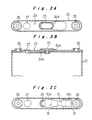
- Fig. 1 is an outer representation of the battery pack 1 according to this embodiment.
- external terminals 6 consisting of a positive terminal, a negative terminal, and a temperature detecting terminal, and bonded a water ingress label 9.
- Fig. 2 is an exploded view of this battery pack 1 showing its constituent elements. These elements and a manufacturing method of the battery pack 1 will be described below in detail.
- the lithium ion rechargeable battery (hereinafter rechargeable battery) 2 accommodates elements for electromotive force in a bottomed tube-like aluminum case 22 having an oval cross section as can be seen from Figs. 3A to 3B, the open end of the case 22 being sealed with a sealing plate 23 by laser welding.
- the sealing plate 23 is joined to the case 22 and serves as the battery's positive electrode; the battery's negative electrode 25 is electrically insulated from the sealing plate 23 by an upper gasket 24a and a lower gasket 24b and protruded at the center of the sealing plate 23.
- On both sides of the sealing plate 23 are mushroom-shaped engaging protrusions 26, 26 that are provided by press-forming.
- Reference numeral 27 denotes a plug for closing a hole for pouring electrolyte; after the injection of electrolyte into the case 22, the hole is closed by the plug 27, which is then welded to the sealing plate 23.
- the engaging protrusions 26 are formed into the mushroom shape as shown by first pressing the sealing plate 23 to provide cylindrical projections at preset locations on the sealing plate 23 and spreading the tops of the projections by pressing. Pressing is not the only way to form the engaging protrusions 26; they may be formed by welding mushroom-shaped or inverted L shape members onto the sealing plate 23, as will be described later.
- thermoelectric fuse heat sensitive element
- a heat insulation sheet 16 is affixed upon the upper face of the temperature fuse 10 as indicated by broken lines, so as to prevent fusion of the temperature fuse 10 during the resin filling process to be described later.
- the heat insulation sheet 16 used here is a 0.6mm thick acrylic foam sheet (VHB: Sumitomo 3M Ltd.) consisting of a foamed acrylic resin sheet provided with an adhesive layer, but other materials may also be used as will be described later.
- connection piece 10b at the other end of the temperature fuse 10 is placed upon an insulating paper 21 affixed on the sealing plate 23 and connected to a negative lead plate 5 to be described later.
- the temperature fuse 10 is fixed on the sealing plate 23 by heat conductive adhesive so as to be heat-coupled to the rechargeable battery 2.
- the circuit substrate 3 includes a circuit for protecting the rechargeable battery 2 from overcharge, over discharge, and over current; on one side that is on the outside are formed the aforementioned external terminals 6 and the test terminal 30 as shown in Fig. 4A, and on the other side that is on the side of the rechargeable battery 2 are mounted electronic components 31 such as ICs and positive and negative solder lands 32, 33 at both ends for the connection with the rechargeable battery 2, as shown in Fig. 4B. Incidentally, circuit patterns and through holes on the circuit board 3 are not shown in these drawings.
- one end of a positive lead plate (connecting member) 4 is soldered to the positive solder land 32, with a piece of insulating paper 34 interposed between the lead plate 4 and the electronic components 31, and one end of the negative lead plate (connecting member) 5 is soldered to the negative solder land 33.
- the circuit substrate 3 is set relative to the rechargeable battery 2 as shown in Fig. 5A such that the other end of the positive lead plate 32 is spot-welded on the face of the sealing plate 23, and the other end of the negative lead plate 33 on the connection piece 10b of the temperature fuse 10.
- the circuit substrate 3 is orthogonal to the face of the sealing plate 23 in this connection state; the positive and negative lead plates 4, 5 are then bent over so that the circuit substrate 3 is substantially parallel to the sealing plate 23 with a certain gap therebetween, as shown in Fig. 5B.
- the rechargeable battery 2 with the circuit substrate 3 thus connected thereto constitutes an object 7 to be resin packed shown in Fig. 11A.
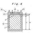
- Resin is filled between the rechargeable battery 2 and the circuit substrate 3 of the object 7 to be resin packed to integrate them. It is important to ensure that the height H from the bottom face of the rechargeable battery 2 to the surface of the circuit substrate 3 where the external terminals 6 are formed is precisely controlled in the resin molding process; the following is a description of a manufacturing method in which this is achieved.
- a lower die 36 of the primary molding die 35 includes a movable part 41 that is movable towards a stationary part 42 by biasing means 45, and the movable part 41 is provided with a vacuum suction part 43.
- the object 7 to be resin packed (only the rechargeable battery 2 and the circuit substrate 3 being illustrated in the drawing) is placed inside the lower die 36 with the movable part 41 retracted, which is then moved forward for the positioning of the rechargeable battery 2, with its bottom being pressed against the inner wall of the stationary part 42.
- the circuit substrate 3 makes tight contact with the wall of the vacuum suction part 43 and is kept in position.
- the height H from the bottom face of the rechargeable battery 2 to the surface of the circuit substrate 3 where the external terminals 6 are formed varies because of variations in the height h of the rechargeable battery 2 and in the position of the circuit substrate 3; with the above structure, however, the circuit substrate 3 is fixed in position by vacuum suction, while the movable part 41 changes its position in accordance with the height h of the rechargeable battery 2, so that the clearance G between the rechargeable battery 2 and the circuit substrate 3 placed inside the lower die 36 is variable, whereby the height H from the bottom face of the rechargeable battery 2 to the surface of the circuit substrate 3 where the external terminals 6 are formed is made constant.
- An upper die 37 shown in Fig. 7 is lowered onto the lower die 36 in which the rechargeable battery 2 and the circuit substrate 3 are placed in position, and resin is injected from a gate 44 in the upper die 37 into the gap between the rechargeable battery 2 and the circuit substrate 3.
- the injected resin surrounds the electronic components 31 and positive and negative lead plates 4, 5 on the circuit substrate 3 and bonds to the circuit substrate 3, as well as surrounds the undercut portions of the engaging protrusions 26 on the sealing plate 23 of the rechargeable battery 2 and bonds to the sealing plate 23, as shown in Fig. 8.
- Hot melt resins are preferably used because they melt at a temperature that does not adversely affect the electronic components 31, battery 2, and temperature fuse 10, and cure as the temperature lowers.
- the resin melts at a relatively low temperature, it is still as hot as 200°C; if it contacts the temperature fuse 10 whose fusion temperature is set 104°C, it may cause fusion of the fuse and destroy the function of the battery pack 1.
- the heat insulation sheet 16 is affixed to cover the temperature fuse 10 as mentioned above so as to provide a shield from heat of resin for the temperature fuse 10.
- an intermediate product 8 shown in Fig. 11B which consists of the rechargeable battery 2 and the circuit substrate 3 united by a primary mold 11 that is formed by the cured resin, is taken out from the lower mold 36.
- This intermediate product 8 is made into a battery pack 1 by providing an outer covering.
- the outer covering is provided by a secondary molding process and a winding sheet affixing process.
- An insulator 14 is attached to the bottom face of the rechargeable battery 2 before the secondary molding.
- the intermediate product 8 is placed in a secondary molding die 46 shown in Fig. 9, so that predetermined parts of the intermediate product 8 are packed with resin.
- a lower die 47 of the secondary molding die 46 has a cavity 50 for accommodating the intermediate product 8; in a wall on one side of the cavity 50 are provided inwardly biased projections 51, 52 for the three external terminals and test terminal, and in the opposite wall is provided an inwardly biased projection 54 for the bottom face of the battery.
- the lower die 47 in this state is then closed by an upper die 48, and resin is filled from a gate 53 in the upper die 48 into the secondary molding die 46.
- the resin is injected into the die 46 from four locations for forming the following: An upper mold 17 fixed on the sealing plate 23 of the rechargeable battery 2 as shown in Fig. 11C and covering the circuit substrate 3 and the primary mold 11 while exposing the external terminals 6 and the test terminal 30 of the intermediate product 8 to the outside as shown in Fig. 10; a lower mold 18 fixed on the bottom face of the rechargeable battery 2 to a predetermined thickness such as to surround the insulator 14; and a connecting part 19 for coupling the upper mold 17 and the lower mold 18 along two corners on one side of the rechargeable battery.
- the connecting part 19 is formed such that the two parts of the arc on one side of the oval cross section of the rechargeable battery 2 at 90 degrees are right-angled, as shown in Fig. 12.
- the upper mold 17, the lower mold 18, and the connecting part 19 together form the secondary mold 12 shown in Fig. 2.
- the upper mold 17 has a step 38 in its periphery near the rechargeable battery, which defines a positioning line along which a winding sheet 13 is wound around the periphery of the rechargeable battery 2.
- the battery operation is then inspected using the test terminal 30, and the water ingress label 9 is bonded in the cavity surrounding the test terminal 30 of the batteries that have passed the inspection to cover the test terminal 30, whereby the battery pack 1 shown in Fig. 1 is obtained.
- the battery pack 1 thus formed has curved shoulders on one flat side corresponding to the arc on both sides of the rechargeable battery 2, while the other two corners on the opposite side are right-angled because of the connecting part 19; this feature, coupled with the asymmetric arrangement of the external terminals 6, prevents the battery to be reversely loaded in equipment.
- the curved corners will snugly fit in rounded corners in the battery accommodation case of the equipment without leaving any dead space.
- the heat insulation sheet 16 is affixed to prevent destruction or degeneration of the heat sensitive element such as the temperature fuse 10 because of the heat of molded resin; another possibility is to means for reducing thermal effects of molten resin on the heat sensitive element during the period in which the resin cures.
- Such heat insulation may be achieved either by affixing a heat insulation sheet on the heat sensitive element, or by covering the heat sensitive element with resin having heat insulating properties.
- Heat insulating resins that are preferably used for covering the heat sensitive element should have a higher melting temperature than that of the filled resin, and include polyphenylene sulfide (PPS), polyamide (PA), polyamideimide (PAI), polyimide (PI), and polyetheretherketone (PEEK). More preferably, the heat insulating resin should have a good bond with the filled resin.
- PPS polyphenylene sulfide
- PA polyamide
- PAI polyamideimide
- PI polyimide
- PEEK polyetheretherketone
- the heat insulation sheet affixed on the heat sensitive element may be a foamed acrylic resin or polyurethane sheet, or a sheet made of the above heat insulating resins, polyurethane, liquid crystal polymers, phenolic resins, or fluorine resins.
- a ceramic, glass wool, or glass cloth sheet impregnated with heat resistant resin may also be employed. These sheets should preferably have a thickness of about 0.3 to 1.0mm for the purposes of heat insulation from molten resin and protection from injection pressure.
- a recess 28 is formed in the sealing plate 23 of the battery 2, and the temperature fuse 10 is placed inside this recess 28.
- a heat insulation sheet 16 may be affixed above the temperature fuse 10 such as to close the open top of the recess 28, or other constituent elements may be employed for stopping resin from flowing into the recess 28, to achieve the same effect.
- the heat of the rechargeable battery 2 conducts to the temperature fuse 10 better, i.e., the temperature fuse 10 detects an abnormal temperature rise in the rechargeable battery 2 with higher precision and response speed.
- connection pieces 10a, 10b at both ends of the temperature fuse 10 are insulated from the sealing plate 23 respectively by the insulating paper 29, 29, while the body of the temperature fuse 10 is fixed inside the recess 28 with a heat conductive adhesive (e.g. silicon resin) and heat-coupled to the rechargeable battery 2.
- a heat conductive adhesive e.g. silicon resin
- a portion of the primary molding die 35 where the temperature fuse 10 will be located may be formed of a material having good heat conductivity (e.g. aluminum) so as to diffuse heat from the resin into the die and reduce heat conduction to the temperature fuse 10, whereby fusion of the temperature fuse 10 during the resin molding is prevented.
- a material having good heat conductivity e.g. aluminum
- the entire primary molding die 35, or at least the stationary part 42 of its lower die 36 may be formed of a material having good heat conductivity (e.g. aluminum alloy) so as to enhance heat conductivity of the portion where the temperature fuse 10 will be located.
- a material having good heat conductivity e.g. aluminum alloy
- both the primary and secondary molding dies 35, 46 are formed with an insulating layer in the parts where active parts of the object 7 to be resin packed or the intermediate product 8 such as positive and negative lead plates 4, 5, external terminals 6 and test terminal 30 will be located, so as to prevent short circuits or leaks caused by a contact between the active parts and molding dies.
- the insulating layer should preferably be formed on the aluminum molding dies by alumite processing or fluorine resin coating processing so that the dies will have insulation as well as excellent heat conductivity.
- the heat insulation sheet is provided as a shield from heat of molding resin for the temperature fuse in the above-described structure, but a connection lead for electrically connecting the rechargeable battery with the substrate may be used instead of the heat insulation sheet to cover the temperature fuse so as to shield it from the heat of the molding resin.
- the temperature fuse 10 in the above-described structure may be replaced by a PTC element.
- a PTC element functions by increasing its normally small resistance in response to a temperature rise to a preset value to stop current flow.
- the PTC element When a large current flows because of a short circuit, for example, the PTC element generates heat to increase resistance to limit the current flow.
- heat-coupled to the rechargeable battery 2 it increases resistance in response to an abnormal temperature rise in the rechargeable battery 2 to instantaneously limit the current flow that is causing the temperature rise and stops the temperature rise.
- a direct contact of molten resin during the molding with the PTC element may destroy its function. Accordingly, a heat shield structure should be provided similarly to the case with the temperature fuse 10.
- the temperature fuse 10 in the above-described structure may be replaced by a bimetal thermostat.
- a bimetal thermostat has a movable contact formed by two types of metal that have different thermal expansion coefficients, and functions to stop current flow by opening the movable contact in response to a temperature rise to a preset value by deformation caused by the difference in the thermal expansion coefficient.
- a large current flows because of a short circuit, for example, it generates heat and raises temperature to stop the current flow.
- heat-coupled to the rechargeable battery 2 it senses an abnormal temperature rise in the rechargeable battery 2 and cuts the current flow that is causing the temperature rise to stop the temperature rise.
- a direct contact of filled resin during the molding with the bimetal thermostat may adversely affect its function due to heat shock. Accordingly, a heat shield structure should be provided similarly to the case with the temperature fuse 10. Good heat insulation will be provided by covering it with a heat insulation sheet, whereby adverse effects on the bimetal element inside will be avoided reliably.
- a bimetal thermostat provided with an outer covering of heat insulating resin excluding the parts that are heat-coupled to the rechargeable battery shields itself from heat during the resin molding, and with such a thermostat, no heat insulation sheet will be necessary.
- Some of these heat sensitive elements with different operating temperatures may be used in combination according to the design.
- a pattern fuse that has an irreversible current cutting function and stops current flow when the current exceeds a preset limit may be provided on the circuit substrate 3, so as to improve the reliability of the battery pack with several elements having current limiting/cutting functions.
- the molten resin will adversely affect the pattern fuse similarly to the case with the temperature fuse 10 and PTC element, causing deterioration in various characteristics of the pattern fuse as mentioned in the paragraph describing the problem to be resolved by the invention. Therefore, the circuit substrate 3 should include an element that shields the pattern fuse portion from heat of the molding resin.
- the structure wherein a heat shield is provided by constituent elements except for the resin as set forth in claim 1, or, the structure wherein a heat insulation member is provided as set forth in claim 2 may be adopted to achieve the effect of eliminating thermal effects as has been described in the foregoing.
- the invention when uniting the rechargeable battery and the substrate formed with external terminals with a gap therebetween by filling resin in the gap to form the battery pack, measures are taken so that the heat sensitive element placed in the gap is not destroyed by the heat of the filled resin; the invention thus provides a battery pack that has a resin-packed rigid structure.
Applications Claiming Priority (5)
| Application Number | Priority Date | Filing Date | Title |
|---|---|---|---|
| JP2002034927 | 2002-02-13 | ||
| JP2002034927 | 2002-02-13 | ||
| JP2002300515 | 2002-10-15 | ||
| JP2002300515A JP4629952B2 (ja) | 2002-02-13 | 2002-10-15 | 二次電池の製造方法 |
| PCT/JP2003/001270 WO2003069697A1 (en) | 2002-02-13 | 2003-02-06 | Method of manufacturing battery pack |
Publications (2)
| Publication Number | Publication Date |
|---|---|
| EP1482577A1 true EP1482577A1 (de) | 2004-12-01 |
| EP1482577A4 EP1482577A4 (de) | 2008-10-08 |
Family
ID=27736486
Family Applications (1)
| Application Number | Title | Priority Date | Filing Date |
|---|---|---|---|
| EP03703233A Withdrawn EP1482577A4 (de) | 2002-02-13 | 2003-02-06 | Verfahren zur herstellung eines batteriepacks |
Country Status (5)
| Country | Link |
|---|---|
| US (1) | US7972721B2 (de) |
| EP (1) | EP1482577A4 (de) |
| JP (1) | JP4629952B2 (de) |
| KR (1) | KR100871525B1 (de) |
| WO (1) | WO2003069697A1 (de) |
Cited By (15)
| Publication number | Priority date | Publication date | Assignee | Title |
|---|---|---|---|---|
| EP1717882A1 (de) * | 2005-04-26 | 2006-11-02 | Samsung SDI Co., Ltd. | Polymerbatteriepack und Verfahren zu dessen Herstellung |
| EP1777760A1 (de) * | 2005-10-21 | 2007-04-25 | Matsushita Electric Industrial Co., Ltd. | Alkalibatterie |
| WO2007149102A1 (en) * | 2006-06-23 | 2007-12-27 | Boston-Power, Inc. | Lithium battery with external positive thermal coefficient layer |
| EP1895610A1 (de) | 2006-08-31 | 2008-03-05 | Samsung SDI Co., Ltd. | Batteriepaket und Herstellungsverfahren dafür |
| WO2008002487A3 (en) * | 2006-06-27 | 2008-06-26 | Boston Power Inc | Integrated current-interrupt device for lithium-ion cells |
| EP1921693A3 (de) * | 2006-11-02 | 2008-11-19 | Sony Corporation | Batterie |
| EP2141763A3 (de) * | 2008-07-03 | 2010-02-17 | Li-Tec Battery GmbH | Akkumulator mit verlängerter Lebensdauer |
| CN1881672B (zh) * | 2005-04-26 | 2010-04-07 | 三星Sdi株式会社 | 聚合物电池组及其制造方法 |
| EP2200113A1 (de) * | 2008-12-22 | 2010-06-23 | Samsung SDI Co., Ltd. | Sekundärbatterie |
| US7838143B2 (en) | 2007-06-22 | 2010-11-23 | Boston-Power, Inc. | CID retention device for Li-ion cell |
| EP2317588A1 (de) * | 2009-10-30 | 2011-05-04 | SB LiMotive Co., Ltd. | Sekundärbatterie |
| US8003241B2 (en) | 2006-06-23 | 2011-08-23 | Boston-Power, Inc. | Lithium battery with external positive thermal coefficient layer |
| EP2372808A1 (de) * | 2010-03-30 | 2011-10-05 | SB LiMotive Co., Ltd. | Sekundärbatterie mit einer Sicherung |
| WO2013113473A1 (de) * | 2012-02-01 | 2013-08-08 | Daimler Ag | Hochvoltbatterie für ein fahrzeug und verfahren zum betreiben einer hochvoltbatterie |
| US8642195B2 (en) | 2008-12-19 | 2014-02-04 | Boston-Power, Inc. | Modular CID assembly for a lithium ion battery |
Families Citing this family (66)
| Publication number | Priority date | Publication date | Assignee | Title |
|---|---|---|---|---|
| JP4494713B2 (ja) | 2001-12-04 | 2010-06-30 | パナソニック株式会社 | 電池パック |
| KR100861166B1 (ko) * | 2002-02-13 | 2008-09-30 | 마츠시타 덴끼 산교 가부시키가이샤 | 전지 팩의 제조방법 |
| JP4629952B2 (ja) | 2002-02-13 | 2011-02-09 | パナソニック株式会社 | 二次電池の製造方法 |
| JP4440548B2 (ja) | 2002-02-13 | 2010-03-24 | パナソニック株式会社 | 電池とその製造方法 |
| JP4589596B2 (ja) * | 2002-03-22 | 2010-12-01 | パナソニック株式会社 | 電池パック |
| KR100496305B1 (ko) * | 2003-05-22 | 2005-06-17 | 삼성에스디아이 주식회사 | 파우치형 리튬 이차 전지와 이의 제조 방법 |
| US8999566B2 (en) * | 2003-05-22 | 2015-04-07 | Samsung Sdi Co., Ltd. | Pouch-type lithium secondary battery and fabrication method thereof |
| JP4130160B2 (ja) | 2003-09-16 | 2008-08-06 | 三洋電機株式会社 | パック電池 |
| EP1715534B1 (de) * | 2004-02-13 | 2014-05-14 | LG Chem, Ltd. | Batteriepack mit verbesserter struktur |
| JP2005243362A (ja) * | 2004-02-25 | 2005-09-08 | Hitachi Maxell Ltd | 電池パックの製造方法 |
| JP4628020B2 (ja) * | 2004-05-31 | 2011-02-09 | 三洋電機株式会社 | パック電池 |
| KR100601519B1 (ko) | 2004-06-22 | 2006-07-19 | 삼성에스디아이 주식회사 | 파우치형 리튬 폴리머 전지 및 그 제조 방법 |
| JP4673019B2 (ja) * | 2004-09-10 | 2011-04-20 | 日立コンピュータ機器株式会社 | 情報処理装置 |
| JP4744127B2 (ja) * | 2004-12-02 | 2011-08-10 | 三洋電機株式会社 | 電池パック |
| KR100877816B1 (ko) * | 2005-01-21 | 2009-01-12 | 주식회사 엘지화학 | 안전성이 향상된 전지팩 |
| JP2007323875A (ja) * | 2006-05-31 | 2007-12-13 | Sony Corp | トップカバー、電池パック及びその製造方法 |
| KR100760784B1 (ko) * | 2006-07-04 | 2007-09-20 | 삼성에스디아이 주식회사 | 이차 전지용 보호회로모듈 및 이를 이용한 전지 팩 |
| KR100876247B1 (ko) * | 2006-10-19 | 2008-12-26 | 삼성에스디아이 주식회사 | 이차전지 및 그 제조방법 |
| KR101030858B1 (ko) * | 2007-09-28 | 2011-04-22 | 삼성에스디아이 주식회사 | 이차전지 |
| KR100947963B1 (ko) * | 2007-09-28 | 2010-03-15 | 삼성에스디아이 주식회사 | 이차 전지용 보호회로 기판과 이를 이용한 이차 전지 |
| JP2009135033A (ja) * | 2007-11-30 | 2009-06-18 | Sanyo Electric Co Ltd | パック電池 |
| JP2009154532A (ja) | 2007-12-05 | 2009-07-16 | Panasonic Corp | 電池パックの製造方法、および製造装置 |
| JP5258398B2 (ja) * | 2008-06-05 | 2013-08-07 | 三洋電機株式会社 | 電池パック |
| US20100055560A1 (en) * | 2008-08-29 | 2010-03-04 | Youngcheol Jang | Secondary battery |
| CN102144317B (zh) * | 2008-09-05 | 2014-10-08 | 松下电器产业株式会社 | 电池组 |
| KR101036086B1 (ko) * | 2008-12-05 | 2011-05-19 | 삼성에스디아이 주식회사 | 이차전지 |
| KR101023910B1 (ko) * | 2008-12-22 | 2011-03-22 | 삼성에스디아이 주식회사 | 배터리 팩 |
| DE102009010146A1 (de) * | 2009-02-23 | 2010-08-26 | Li-Tec Battery Gmbh | Galvanische Zelle mit mehrteiligem Gehäuse |
| US8557437B2 (en) * | 2009-03-25 | 2013-10-15 | Tdk Corporation | Electrode comprising protective layer for lithium ion secondary battery and lithium ion secondary battery |
| JP5383282B2 (ja) * | 2009-03-30 | 2014-01-08 | 三洋電機株式会社 | 電池パック用中間品、電池パック及び電池パックの製造方法 |
| US9246140B2 (en) | 2009-07-09 | 2016-01-26 | Samsung Sdi Co., Ltd. | Rechargeable battery with a cap assembly having a first tab located outside of the case |
| US8597807B2 (en) * | 2009-08-11 | 2013-12-03 | Samsung Sdi Co., Ltd. | Secondary battery including a thermally insulating sheet having a recess for receiving a thermal fuse |
| US8916278B2 (en) | 2009-08-12 | 2014-12-23 | Samsung Sdi Co., Ltd. | Heat transfer member for battery pack |
| US8877361B2 (en) | 2009-09-01 | 2014-11-04 | Samsung Sdi Co., Ltd. | Rechargeable battery |
| KR101075356B1 (ko) * | 2009-09-09 | 2011-10-19 | 삼성에스디아이 주식회사 | 배터리 팩 |
| US9048477B2 (en) | 2009-09-09 | 2015-06-02 | Samsung Sdi Co., Ltd. | Battery pack |
| US9099732B2 (en) | 2010-06-11 | 2015-08-04 | Samsung Sdi Co., Ltd. | Rechargeable battery having a fuse with an insulating blocking member |
| JP2012079513A (ja) * | 2010-09-30 | 2012-04-19 | Gs Yuasa Corp | 異常履歴保持装置 |
| US9029033B2 (en) * | 2010-10-08 | 2015-05-12 | GM Global Technology Operations LLC | Composite end cell thermal barrier with an electrically conducting layer |
| US9478774B2 (en) | 2010-12-02 | 2016-10-25 | Samsung Sdi Co., Ltd. | Rechargeable battery |
| KR101198026B1 (ko) * | 2010-12-02 | 2012-11-06 | 주식회사 엘지화학 | 신규한 구조의 이차전지 팩 |
| KR101219253B1 (ko) * | 2011-03-31 | 2013-01-09 | 삼성에스디아이 주식회사 | 배터리 팩 |
| KR101274806B1 (ko) | 2011-07-26 | 2013-06-13 | 로베르트 보쉬 게엠베하 | 이차 전지 |
| US9634299B2 (en) | 2011-09-06 | 2017-04-25 | Samsung Sdi Co., Ltd. | Rechargeable battery |
| KR101683210B1 (ko) | 2011-11-17 | 2016-12-07 | 삼성에스디아이 주식회사 | 이차 전지 |
| US9343716B2 (en) | 2011-12-29 | 2016-05-17 | Apple Inc. | Flexible battery pack |
| US8993155B2 (en) * | 2012-07-17 | 2015-03-31 | Sanyo Electric Co., Ltd. | Prismatic secondary battery |
| DE102012213100B4 (de) * | 2012-07-25 | 2015-08-06 | Volkswagen Varta Microbattery Forschungsgesellschaft Mbh & Co. Kg | Batterie mit Thermoschalter und pneumatisch betätigbarem Schalter und Verfahren zum sicheren Betreiben der Batterie |
| US9812680B2 (en) | 2012-08-30 | 2017-11-07 | Apple Inc. | Low Z-fold battery seal |
| US20140147703A1 (en) * | 2012-11-28 | 2014-05-29 | Apple Inc. | Battery safety circuit and tab placement and orientation |
| US9593969B2 (en) | 2013-12-27 | 2017-03-14 | Apple Inc. | Concealed electrical connectors |
| USD747264S1 (en) * | 2014-01-30 | 2016-01-12 | Nikon Corporation | Battery |
| US9479007B1 (en) | 2014-02-21 | 2016-10-25 | Apple Inc. | Induction charging system |
| US20150255776A1 (en) | 2014-03-06 | 2015-09-10 | Apple Inc. | Battery Pack System |
| US9455582B2 (en) | 2014-03-07 | 2016-09-27 | Apple Inc. | Electronic device and charging device for electronic device |
| FR3022166B1 (fr) * | 2014-06-16 | 2016-07-22 | Centre Technique De L'industrie Du Decolletage | Support d'outil instrumente et porte-outil associe |
| US9917335B2 (en) | 2014-08-28 | 2018-03-13 | Apple Inc. | Methods for determining and controlling battery expansion |
| USD764401S1 (en) * | 2014-09-08 | 2016-08-23 | Parrot Drone | Battery for a remote-controlled toy |
| USD762566S1 (en) * | 2014-09-08 | 2016-08-02 | Parrot Drones | Battery for a headphone |
| CN114512746A (zh) | 2015-10-27 | 2022-05-17 | 株式会社半导体能源研究所 | 电池及电池的制造方法 |
| US10637017B2 (en) | 2016-09-23 | 2020-04-28 | Apple Inc. | Flexible battery structure |
| KR102651576B1 (ko) * | 2016-10-18 | 2024-03-27 | 삼성전자주식회사 | 배터리 모듈을 포함하는 전자 장치 및 제조 방법 |
| JP6950796B2 (ja) * | 2017-10-05 | 2021-10-13 | カシオ計算機株式会社 | 電池モジュールの製造方法 |
| JP6750591B2 (ja) | 2017-10-05 | 2020-09-02 | カシオ計算機株式会社 | インサート成形方法及びインサート成形部品 |
| WO2019100076A1 (en) * | 2017-11-20 | 2019-05-23 | Johnson Controls Technology Company | Overcharge protection device with uneven terminal pads |
| JP2023157123A (ja) * | 2022-04-14 | 2023-10-26 | 日本特殊陶業株式会社 | 液体加熱装置 |
Citations (4)
| Publication number | Priority date | Publication date | Assignee | Title |
|---|---|---|---|---|
| JPH11289168A (ja) * | 1998-03-31 | 1999-10-19 | Next:Kk | 電気的装置のケースへの収納構造 |
| JP2000315483A (ja) * | 1999-03-02 | 2000-11-14 | Kyocera Corp | バッテリー構造及びその製造方法 |
| WO2003003485A1 (en) * | 2001-06-28 | 2003-01-09 | Matsushita Electric Industrial Co., Ltd. | Cell and cell pack |
| EP1422771A1 (de) * | 2001-08-07 | 2004-05-26 | Matsushita Electric Industrial Co., Ltd. | Sekundärbatterie mit wasserfreiem elektrolyt |
Family Cites Families (36)
| Publication number | Priority date | Publication date | Assignee | Title |
|---|---|---|---|---|
| US3948441A (en) * | 1974-08-13 | 1976-04-06 | Robertshaw Controls Company | Time variable thermostat |
| JPS62184760A (ja) | 1986-02-07 | 1987-08-13 | Matsushita Electric Ind Co Ltd | 蓄電池の極柱封止方法 |
| JPS6319774A (ja) | 1986-07-11 | 1988-01-27 | Nec Corp | 密閉形鉛蓄電池 |
| JPS6472458A (en) * | 1987-09-14 | 1989-03-17 | Fuji Electrochemical Co Ltd | Packed cell |
| US4973936A (en) * | 1989-04-27 | 1990-11-27 | The United States Of America As Represented By The Administrator Of The National Aeronautics And Space Adminstration | Thermal switch disc for short circuit protection of batteries |
| JPH05159758A (ja) * | 1991-12-02 | 1993-06-25 | Matsushita Electric Ind Co Ltd | 密閉形鉛蓄電池の製造法 |
| JPH0757721A (ja) * | 1993-08-06 | 1995-03-03 | Matsushita Electric Ind Co Ltd | Ptc装置およびptc装置を備えた構成電池 |
| JP3270644B2 (ja) * | 1994-11-30 | 2002-04-02 | 株式会社日立国際電気 | 電池パックおよびその製造方法 |
| JPH09134714A (ja) * | 1995-11-07 | 1997-05-20 | Wako Denshi Kk | 安全装置用の皿バネ |
| EP0739047A3 (de) * | 1995-04-21 | 1999-04-07 | Wako Electronics Co., Ltd. | Sicherheitsvorrichtung für einen Akkumulator |
| WO1997006538A1 (en) * | 1995-08-07 | 1997-02-20 | K.K. Raychem | Ptc device and battery pack using the same |
| JPH1154110A (ja) * | 1997-07-31 | 1999-02-26 | N Ii C Mori Energ Kk | 正特性温度素子を備えた電池保護装置 |
| US6210824B1 (en) * | 1998-01-15 | 2001-04-03 | Texas Instruments Incorporated | Current interrupt apparatus for electrochemical cells |
| DE19829142A1 (de) * | 1998-06-30 | 2000-01-05 | Manhattan Scientifics Inc | Gasdichter Verbund aus Bipolarplatte und Membran-Elektroden-Einheit von Polymerelektrolytmembran-Brennstoffzellen |
| EP1033766B1 (de) * | 1998-09-11 | 2009-01-07 | Panasonic Corporation | Batteriepaket |
| TW432736B (en) * | 1999-02-23 | 2001-05-01 | Sanyo Electric Co | Pack battery |
| JP3454748B2 (ja) * | 1999-02-26 | 2003-10-06 | 三洋電機株式会社 | パック電池 |
| CN1180507C (zh) * | 1999-03-30 | 2004-12-15 | 松下电器产业株式会社 | 具备电池保护电路的蓄电池 |
| KR100593127B1 (ko) * | 1999-05-17 | 2006-06-26 | 마츠시타 덴끼 산교 가부시키가이샤 | 2차 전지의 보호회로 및 보호소자 |
| JP3190024B2 (ja) * | 1999-08-18 | 2001-07-16 | 日本テキサス・インスツルメンツ株式会社 | バッテリ保護装置及びその製造方法 |
| JP4904614B2 (ja) * | 2000-06-22 | 2012-03-28 | パナソニック株式会社 | 電池パックおよびその製造方法 |
| JP2002110121A (ja) * | 2000-09-26 | 2002-04-12 | Gs-Melcotec Co Ltd | 電池パック |
| JP3614767B2 (ja) * | 2000-10-20 | 2005-01-26 | 松下電器産業株式会社 | 電気製品の外装体形成方法 |
| JP3576484B2 (ja) * | 2000-11-29 | 2004-10-13 | 松下電器産業株式会社 | 樹脂封止成形装置 |
| JP3471323B2 (ja) * | 2001-02-27 | 2003-12-02 | 京セラ株式会社 | バッテリーとこれを備えた携帯端末 |
| JP2002373630A (ja) * | 2001-06-13 | 2002-12-26 | Nec Tokin Tochigi Ltd | 電池パック |
| JP2003162987A (ja) * | 2001-06-28 | 2003-06-06 | Matsushita Electric Ind Co Ltd | 基板一体化電池及び電池パック |
| JP3643792B2 (ja) * | 2001-06-29 | 2005-04-27 | 三洋電機株式会社 | パック電池とその製造方法 |
| JP3766001B2 (ja) * | 2001-07-06 | 2006-04-12 | 京セラ株式会社 | バッテリーとその製造方法 |
| JP3762683B2 (ja) * | 2001-10-26 | 2006-04-05 | 三洋電機株式会社 | 電流遮断素子を内蔵する電池パック |
| JP3778841B2 (ja) * | 2001-10-26 | 2006-05-24 | 三洋電機株式会社 | 電池パックの製造方法 |
| US6803144B2 (en) * | 2001-11-01 | 2004-10-12 | Nokia Corporation | Battery pack for electronic device |
| US6824917B2 (en) * | 2001-12-11 | 2004-11-30 | Nokia Corporation | Battery system for a portable electronic device |
| JP4629952B2 (ja) | 2002-02-13 | 2011-02-09 | パナソニック株式会社 | 二次電池の製造方法 |
| JP4440548B2 (ja) * | 2002-02-13 | 2010-03-24 | パナソニック株式会社 | 電池とその製造方法 |
| JP4589596B2 (ja) * | 2002-03-22 | 2010-12-01 | パナソニック株式会社 | 電池パック |
-
2002
- 2002-10-15 JP JP2002300515A patent/JP4629952B2/ja not_active Expired - Lifetime
-
2003
- 2003-02-06 US US10/502,824 patent/US7972721B2/en not_active Expired - Fee Related
- 2003-02-06 EP EP03703233A patent/EP1482577A4/de not_active Withdrawn
- 2003-02-06 KR KR1020047011211A patent/KR100871525B1/ko not_active IP Right Cessation
- 2003-02-06 WO PCT/JP2003/001270 patent/WO2003069697A1/ja active Application Filing
Patent Citations (5)
| Publication number | Priority date | Publication date | Assignee | Title |
|---|---|---|---|---|
| JPH11289168A (ja) * | 1998-03-31 | 1999-10-19 | Next:Kk | 電気的装置のケースへの収納構造 |
| JP2000315483A (ja) * | 1999-03-02 | 2000-11-14 | Kyocera Corp | バッテリー構造及びその製造方法 |
| WO2003003485A1 (en) * | 2001-06-28 | 2003-01-09 | Matsushita Electric Industrial Co., Ltd. | Cell and cell pack |
| EP1403942A1 (de) * | 2001-06-28 | 2004-03-31 | Matsushita Electric Industrial Co., Ltd. | Zelle und zellenpack |
| EP1422771A1 (de) * | 2001-08-07 | 2004-05-26 | Matsushita Electric Industrial Co., Ltd. | Sekundärbatterie mit wasserfreiem elektrolyt |
Non-Patent Citations (1)
| Title |
|---|
| See also references of WO03069697A1 * |
Cited By (28)
| Publication number | Priority date | Publication date | Assignee | Title |
|---|---|---|---|---|
| CN1881672B (zh) * | 2005-04-26 | 2010-04-07 | 三星Sdi株式会社 | 聚合物电池组及其制造方法 |
| EP1717882A1 (de) * | 2005-04-26 | 2006-11-02 | Samsung SDI Co., Ltd. | Polymerbatteriepack und Verfahren zu dessen Herstellung |
| US8691425B2 (en) | 2005-04-26 | 2014-04-08 | Samsung Sdi Co., Ltd. | Polymer battery pack and manufacturing method of the same |
| US7887949B2 (en) | 2005-04-26 | 2011-02-15 | Samsung Sdi Co., Ltd. | Polymer battery pack and method of manufacturing the same |
| EP1777760A1 (de) * | 2005-10-21 | 2007-04-25 | Matsushita Electric Industrial Co., Ltd. | Alkalibatterie |
| CN101501882B (zh) * | 2006-06-23 | 2011-10-26 | 波士顿电力公司 | 具有正热系数外层的锂电池 |
| WO2007149102A1 (en) * | 2006-06-23 | 2007-12-27 | Boston-Power, Inc. | Lithium battery with external positive thermal coefficient layer |
| US8003241B2 (en) | 2006-06-23 | 2011-08-23 | Boston-Power, Inc. | Lithium battery with external positive thermal coefficient layer |
| WO2008002487A3 (en) * | 2006-06-27 | 2008-06-26 | Boston Power Inc | Integrated current-interrupt device for lithium-ion cells |
| US8071233B2 (en) | 2006-06-27 | 2011-12-06 | Boston-Power, Inc. | Integrated current-interrupt device for lithium-ion cells |
| US8143847B2 (en) | 2006-08-31 | 2012-03-27 | Samsung Sdi Co., Ltd. | Battery pack and manufacturing method thereof |
| EP1895610A1 (de) | 2006-08-31 | 2008-03-05 | Samsung SDI Co., Ltd. | Batteriepaket und Herstellungsverfahren dafür |
| US8758933B2 (en) | 2006-11-02 | 2014-06-24 | Sony Corporation | Battery with electrode arrangement in relation to the holder |
| EP1921693A3 (de) * | 2006-11-02 | 2008-11-19 | Sony Corporation | Batterie |
| US8309251B2 (en) | 2006-11-02 | 2012-11-13 | Sony Corporation | Battery with electrode arrangement in relation to the holder |
| US8012615B2 (en) | 2007-06-22 | 2011-09-06 | Boston-Power, Inc. | CID retention device for Li-ion cell |
| US7838143B2 (en) | 2007-06-22 | 2010-11-23 | Boston-Power, Inc. | CID retention device for Li-ion cell |
| US8679670B2 (en) | 2007-06-22 | 2014-03-25 | Boston-Power, Inc. | CID retention device for Li-ion cell |
| EP2141763A3 (de) * | 2008-07-03 | 2010-02-17 | Li-Tec Battery GmbH | Akkumulator mit verlängerter Lebensdauer |
| US9293758B2 (en) | 2008-12-19 | 2016-03-22 | Boston-Power, Inc. | Modular CID assembly for a lithium ion battery |
| US8642195B2 (en) | 2008-12-19 | 2014-02-04 | Boston-Power, Inc. | Modular CID assembly for a lithium ion battery |
| US8628870B2 (en) | 2008-12-22 | 2014-01-14 | Samsung Sdi Co., Ltd. | Secondary battery |
| EP2200113A1 (de) * | 2008-12-22 | 2010-06-23 | Samsung SDI Co., Ltd. | Sekundärbatterie |
| US8455134B2 (en) | 2009-10-30 | 2013-06-04 | Samsung Sdi Co., Ltd. | Secondary battery with insulating film between current collectors and a case |
| EP2317588A1 (de) * | 2009-10-30 | 2011-05-04 | SB LiMotive Co., Ltd. | Sekundärbatterie |
| EP2372808A1 (de) * | 2010-03-30 | 2011-10-05 | SB LiMotive Co., Ltd. | Sekundärbatterie mit einer Sicherung |
| US9059459B2 (en) | 2010-03-30 | 2015-06-16 | Samsung Sdi Co., Ltd. | Secondary battery |
| WO2013113473A1 (de) * | 2012-02-01 | 2013-08-08 | Daimler Ag | Hochvoltbatterie für ein fahrzeug und verfahren zum betreiben einer hochvoltbatterie |
Also Published As
| Publication number | Publication date |
|---|---|
| EP1482577A4 (de) | 2008-10-08 |
| KR100871525B1 (ko) | 2008-12-05 |
| JP4629952B2 (ja) | 2011-02-09 |
| US20050112456A1 (en) | 2005-05-26 |
| WO2003069697A1 (en) | 2003-08-21 |
| JP2003308815A (ja) | 2003-10-31 |
| KR20040085155A (ko) | 2004-10-07 |
| US7972721B2 (en) | 2011-07-05 |
Similar Documents
| Publication | Publication Date | Title |
|---|---|---|
| US7972721B2 (en) | Method for manufacturing battery pack | |
| US7429432B2 (en) | Battery pack having circuit substrate resin molded to battery | |
| EP1492176B1 (de) | Batteriepack | |
| US6861821B2 (en) | Battery with resin integrated resin substrate | |
| US7759001B2 (en) | Battery and method of manufacturing the battery | |
| JP4841685B2 (ja) | 電池パック | |
| KR100561308B1 (ko) | 이차전지 | |
| KR100699686B1 (ko) | 보호회로 모듈 성형체 및 그것을 포함하는 전지 | |
| KR101094039B1 (ko) | 전류차단소자 및 이를 구비한 이차 전지 | |
| JP5517165B2 (ja) | 密閉型電池 | |
| JP2003242947A (ja) | 電池パックの製造方法 | |
| JP2003162987A (ja) | 基板一体化電池及び電池パック | |
| JP2003282039A (ja) | 電池パック | |
| KR100561311B1 (ko) | 이차전지 | |
| JP2003282038A (ja) | 電池パック | |
| JP4989113B2 (ja) | パック電池とパック電池の製造方法 | |
| JP2003086070A (ja) | 温度ヒューズおよびそれを用いた電池 |
Legal Events
| Date | Code | Title | Description |
|---|---|---|---|
| PUAI | Public reference made under article 153(3) epc to a published international application that has entered the european phase |
Free format text: ORIGINAL CODE: 0009012 |
|
| 17P | Request for examination filed |
Effective date: 20040907 |
|
| AK | Designated contracting states |
Kind code of ref document: A1 Designated state(s): AT BE BG CH CY CZ DE DK EE ES FI FR GB GR HU IE IT LI LU MC NL PT SE SI SK TR |
|
| RIN1 | Information on inventor provided before grant (corrected) |
Inventor name: KOZU, KATSUMI Inventor name: MIZUTA, MASAHIRO Inventor name: TORIYAMA, KOICHI Inventor name: OSAWA, YOSHIKI Inventor name: ISHIMARU, TAKESHI Inventor name: CHIKADA, TATSUHISA Inventor name: KATAOKA, SATOSHI Inventor name: MORI, IICHIRO |
|
| A4 | Supplementary search report drawn up and despatched |
Effective date: 20080904 |
|
| RAP1 | Party data changed (applicant data changed or rights of an application transferred) |
Owner name: PANASONIC CORPORATION |
|
| 17Q | First examination report despatched |
Effective date: 20090211 |
|
| STAA | Information on the status of an ep patent application or granted ep patent |
Free format text: STATUS: THE APPLICATION IS DEEMED TO BE WITHDRAWN |
|
| 18D | Application deemed to be withdrawn |
Effective date: 20090822 |