EP1481882A2 - Lenkungsdämpfer - Google Patents
Lenkungsdämpfer Download PDFInfo
- Publication number
- EP1481882A2 EP1481882A2 EP20040012506 EP04012506A EP1481882A2 EP 1481882 A2 EP1481882 A2 EP 1481882A2 EP 20040012506 EP20040012506 EP 20040012506 EP 04012506 A EP04012506 A EP 04012506A EP 1481882 A2 EP1481882 A2 EP 1481882A2
- Authority
- EP
- European Patent Office
- Prior art keywords
- steering
- damping force
- fluid path
- angular velocity
- fluid
- Prior art date
- Legal status (The legal status is an assumption and is not a legal conclusion. Google has not performed a legal analysis and makes no representation as to the accuracy of the status listed.)
- Granted
Links
Images


Classifications
-
- F—MECHANICAL ENGINEERING; LIGHTING; HEATING; WEAPONS; BLASTING
- F16—ENGINEERING ELEMENTS AND UNITS; GENERAL MEASURES FOR PRODUCING AND MAINTAINING EFFECTIVE FUNCTIONING OF MACHINES OR INSTALLATIONS; THERMAL INSULATION IN GENERAL
- F16F—SPRINGS; SHOCK-ABSORBERS; MEANS FOR DAMPING VIBRATION
- F16F9/00—Springs, vibration-dampers, shock-absorbers, or similarly-constructed movement-dampers using a fluid or the equivalent as damping medium
- F16F9/10—Springs, vibration-dampers, shock-absorbers, or similarly-constructed movement-dampers using a fluid or the equivalent as damping medium using liquid only; using a fluid of which the nature is immaterial
- F16F9/14—Devices with one or more members, e.g. pistons, vanes, moving to and fro in chambers and using throttling effect
- F16F9/145—Devices with one or more members, e.g. pistons, vanes, moving to and fro in chambers and using throttling effect involving only rotary movement of the effective parts
-
- B—PERFORMING OPERATIONS; TRANSPORTING
- B62—LAND VEHICLES FOR TRAVELLING OTHERWISE THAN ON RAILS
- B62K—CYCLES; CYCLE FRAMES; CYCLE STEERING DEVICES; RIDER-OPERATED TERMINAL CONTROLS SPECIALLY ADAPTED FOR CYCLES; CYCLE AXLE SUSPENSIONS; CYCLE SIDE-CARS, FORECARS, OR THE LIKE
- B62K21/00—Steering devices
- B62K21/08—Steering dampers
Definitions
- the present invention relates to a steering damper.
- a type of steering damper which controls damping force generated in the steering system by controlling a pressure control valve provided in a fluid path of a steering damper body so as to change damping force generated by the pressure control valve (for example, refer to Japanese Examined Patent Application, Second Publication No. H7-74023).
- a load applied to a front wheel of a vehicle is measured, and electrical current supplied to a solenoid that is installed in a pressure control valve is controlled so as to increase a damping force when the load is decreased.
- the relationship between a steering angular velocity and the damping force of the steering system is set to be basically linear, when the steering damper is configured so that an operation force at the steering handle at the beginning of a steering operation is set to be low, the vibrations due to road surface disturbances in a low steering angular velocity region during high speed driving cannot be absorbed.
- the steering damper is configured so as to absorb the vibrations due to road surface disturbances in a low steering angular velocity region during high speed driving, the operation force at the steering handle at the beginning of a steering operation becomes high.
- the present invention was made in view of the above circumferences, and an object thereof is to provide a steering damper which simultaneously achieves two objects of setting the operation force at the steering handle at the beginning of a steering operation to be low, and of absorbing the vibrations due to road surface disturbances in a low steering angular velocity region during high speed driving.
- the present invention provides a steering damper including: a steering damper body installed in a steering system of a vehicle, and having a fluid path therein; and a pressure control valve for controlling a damping force in the steering system, and provided in the fluid path, wherein the pressure control valve controls the damping force so that an increasing rate of the damping force with respect to a steering angular velocity when the steering angular velocity is large is lower than that when the steering angular velocity is small.
- the pressure control valve may control the damping force so that the increasing rate of the damping force with respect to the steering angular velocity when the steering angular velocity is larger than a predetermined value is lower than that when the steering angular velocity is smaller than or equal to the predetermined value.
- the steering damper body may include a fluid chamber having an entrance and an exit, a first fluid path connected to the entrance of the fluid chamber, a second fluid path connected to the exit of the fluid chamber, and a connection fluid path connecting the first fluid path to the second fluid path.
- the pressure control valve may be a relief valve provided in the connection fluid path.
- the present invention further provides a steering damper including: a steering damper body installed in a steering system of a vehicle, and having a fluid path therein; and a pressure control valve for controlling a damping force in the steering system, and provided in the fluid path, wherein the pressure control valve controls the damping force so that an increasing rate of the damping force with respect to a steering angular velocity when the damping force is large is lower than that when the damping force is small.
- the pressure control valve may control the damping force so that the increasing rate of the damping force with respect to the steering angular velocity when the damping force is larger than a predetermined value is lower than that when the damping force is smaller than or equal to the predetermined value.
- the relationship between the steering angular velocity and the damping force of the steering system is not linear over the entire steering angular velocity region, and the steering damper is configured so that the increasing rate of the damping force with respect to the steering angular velocity of the steering system when the steering angular velocity is large is lower than that when the steering angular velocity is small, or the increasing rate of the damping force when the damping force is large is lower than that when the damping force is small; therefore, the damping force can be quickly increased as the steering angular velocity is increased from a state in which the steering angular velocity is small and the damping force is low.
- the two objects of setting the operation force at the steering handle at the beginning of a steering operation to be low, and of absorbing the vibrations due to road surface disturbances in a low steering angular velocity region during high speed driving can be simultaneously achieved.
- the damping force will not exceed a predetermined value.
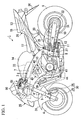
- a motorcycle 1 is provided with a motorcycle body frame 2 in the approximate center, and a front fork 5 which supports a front wheel 4 is steerably supported through a steering stem 6 by a head pipe 3 which is provided in the front end of a motorcycle body frame 2.
- a main frame 7 is provided from the head pipe 3 of the motorcycle body frame 2 so as to extend obliquely behind and downward after being separated to the right and left, and to extend downwardly through bends.
- Pivot sections 8 are provided in the approximately central front end sections of the parts of the main frame 7 extending downward, and rear forks 10 supporting a rear wheel 9 are supported rockably by the pivot sections 8.
- slightly rear sections of the parts supported by the pivot sections 8 of the rear forks 10 are joined to the main frame 7 through rear cushions 11 and link sections 12.
- a seat frame 13 is joined to rear sections of the main frame 7.
- a fuel tank 14 is arranged above the main frame 7, and an engine body 15 of a water-cooled parallel four-cylinder engine is arranged below the main frame 7. From the front part of the main frame 7, engine hangers 16 are extended downwardly, and the engine hangers 16 support the engine body 15 with other junctions for basic engine support which are provided in the main frame 7.
- a rider's seat 17 and a pillion seat 18 are respectively supported by a seat frame 13.
- rider's steps 19 are attached in the rear sections of the pivot sections 8 of the motorcycle body frame 2
- co-rider's steps 20 are attached in the lower portion of the seat frame 13.
- a pair of right and left handles 21 and 21 is attached to the top end of the front fork 5 through a top bridge 49.
- a front nose section of the motorcycle 1 is covered with a front cowl 25, and the vicinity of the seat frame 13 is covered by a rear cowl 26.
- a retractable prop stand 27 is arranged in a lower left side of the motorcycle body frame 2, the prop stand 27 which supports the motorcycle body of the motorcycle 1 in a rising state oblique to a left side.
- a front brake device 30 is constituted by a brake caliper 28 being attached to a bottom end section of the front fork 5 and a brake rotor 29, corresponding to the brake caliper 28, being attached to a front wheel 4.
- a front fender 31 covering over the front wheel 4 is attached to a bottom end section of the front fork 5.
- a rear sprocket 32 is attached to a left side of a rear wheel 9 so as to rotate with the rear wheel 9 integrally.
- a drive chain 34 is looped over the rear sprocket 32 and a drive sprocket 33 arranged in a lower left side of the engine body 15. Then, a driving force of the engine body 15 is transmitted to the rear wheel 9.
- a front rear fender 35 covering over an upper front side of the rear fork 10 is attached to an upper portion of the rear wheel 9, and a rear fender 36 covering over an upper rear side of the rear wheel 9 is attached to a lower portion of the rear cowl 26.
- a rear brake device which has the same structure as the front brake device 30 of the front wheel 4 is provided in the rear frame 10.
- a cylinder body 40 of the engine body 15 is arranged so as to slightly incline forward over a crankcase 41.
- Throttle bodies 42 corresponding to respective cylinders are joined to rear sections of the cylinder body 40, and respective throttle bodies 42 are joined to an air cleaner case 43 located between the main frame 7 and fuel tank 14.
- exhaust pipes 44 corresponding to respective cylinders are joined to front parts of the cylinder body 40.
- the exhaust pipes 44 extend forward from a front wall 45 of the cylinder body 40, are curved and extend downwardly, extend in front of and under the crankcase 41, and extend to a location behind the engine body 15.
- the above-mentioned steering stem 6, a top bridge 49 located above a bottom bridge of the steering stem 6 in parallel to the bottom bridge, the steering handle 21, and the like constitute the steering system 50 which steers the front wheel 4.
- the steering system 50 is provided with the steering damper 51 (refer to FIGS. 2 and 3).
- the steering damper 51 is for decreasing the vibration of the steering handle 21 which is caused by a kickback, etc., or absorbing vibration in a low steering angular velocity region which is caused by road surface disturbances during high speed driving.
- two types of steering dampers are known, one is a rod type and the other is a rotary type, and a rotary type steering damper 51, which is suitable for reducing the size thereof, is used in this embodiment.
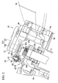
- the steering damper 51 includes a steering damper main body 51 A being constituted by a housing 52 and a shaft 53 which penetrates a bottom face section of the housing 52 and protruding outside, and a pressure control valve 68 intermediately installed in the fluid path of the steering damper main body 51A.
- the housing 52 is attached to a junction 3a provided with extending behind with the head pipe 3 through first and second brackets 54 and 55.
- the shaft 53 is attached to the top bridge 49 through a link mechanism 56.
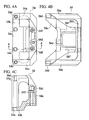
- the first bracket 54 has an approximately enclosed type shape whose inside is scooped out, and has right and left side wall sections 54a and 54a, a bottom plate section 54b, and a leg section 54c which has an approximately Y shape and is connected to rear edge sections of the side plate section 54a, and bottom plate section 54b. Then, respective mounting holes 54d, 54d, and 54d are formed in top face sections of the side wall sections 54a and 54a, and a top face section of the leg section 54c, and the above-mentioned steering damper 51 is bolted through the mounting holes 54d.
- mounting holes 54e and 54e are formed in the bottom plate section 54b, and mounting holes 54f and 54f are formed in the leg section 54c respectively, and the first bracket 54 is bolted to the junction 3a of the head pipe 3 through the mounting holes 54e.
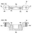
- the second bracket 55 has a base 55a formed in an approximately rectangular parallelepiped shape, and right and left overhang sections 55b and 55b protruding from both sides of the base upward.
- Mounting holes 55c and 55c are formed in the base 55a so as to be coaxial with the mounting holes 54f and 54f of the first bracket 54. Then, one bolt is inserted into the mounting holes 54f and 55c, both of which are coaxial, in the state that both the first bracket 54 and second bracket 55 are stacked. With the bolt, the second bracket 55 is attached to the junction 3a of the above-mentioned head pipe 3 with the first bracket 54.
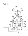
- an end section 60a of an arm 60 is attached to a shaft 53 which protrudes under the steering damper main body 51 A.
- An end section of an elongated figure-8-shape linkage 63 is spherically supported by another end section 60b of the arm 60, which is branched into two, through a bolt 61, a ball member 62 fitted on the outer periphery of the bolt 61, and the like.
- another end section of the linkage 63 is spherically supported by a junction 49a, formed in the top bridge 49, through a bolt 64 and a ball member 65 fitted on the outer periphery of the bolt 64. That is, the link mechanism 56 which transmits a motion of the top bridge to the shaft 53 is constituted by the arm 60, bolts 61 and 64, ball members 62 and 65, and linkage 63.
- the housing 52 of the steering damper main body 51 A is attached in the top bridge 49 so as to extend backward.
- a linear solenoid 69 which drives and controls a pressure control valve 68 is located below an extruding section 52a extending from the top bridge 49 of the housing 52 backward.
- a concavity 14a is formed in the front part of the fuel tank 14.
- reference numeral 70 denotes an ignition switch located ahead of the head pipe 3.
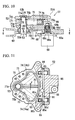
- the housing 52 of the steering damper main body 51 A is constituted by a body 71 and a cap 72.
- a fan-like concavity 73 is formed in a top face section of the body 71, and a fluid chamber 74 is formed by the concavity 73 being covered by the cap 72.
- the fluid chamber 74 is partitioned by a vane 75 into two, right and left, fluid chambers 74a and 74b.
- a base 75a of the vane 75 is formed in a cylindrical shape, and the shaft 53 is joined with the cylindrical section in a fixed state so as to rotate integrally with the vane 75 through fixing means such as a spline.
- the vane 75 is supported by the shaft 53 in a rockable manner with respect to the housing 52.
- a groove 75b is continuously formed on a top end, on a bottom end, and on a rear end of the vane 75, each of which faces the inner circumferential surface of the fluid chamber 74.
- a sealing member 76 which is formed in a U-shape so as to match the shape of the groove 75b, is fitted in the groove 75b.
- the groove 75b and sealing member 76 do not reach the shaft 53, but the groove 75b is formed, and the sealing member 76 is fitted in the groove 75b, up to points separated from the shaft 53.
- washers 77a and 77b for sealing are fitted so as to abut against upper and lower face sections of the base 75a of the vane 75. Furthermore, portions of the outer peripheries of washers 77a and 77b for the sealing of upper and lower sides thereof abut against the sealing member 76.
- two fluid chambers 74a and 74b partitioned inside the housing 52 are maintained to be sealed from each other in a fluid-tight manner, and are also maintained to be sealed from the shaft 53 in a fluid-tight manner, by the sealing member 76 and washers 77a and 77b for sealing.
- a bushing 78 is fitted on an upper part of an area where the washer 77a for the sealing of the shaft 53 is fitted, and a circlip 79 is fitted on a lower part of an area where the washer 77a for sealing is fitted, respectively.
- a bushing 80 and an oil seal 81 are fitted on a lower part of an area where the washer 77b for the sealing of the lower side of the shaft 53 is fitted, respectively.
- the fluid paths 83 and 84 in a discharge side where hydraulic fluid is exhausted from the right and left fluid chambers 74a and 74b are formed in the body 71 of the above-mentioned housing 52 so that they extend back further from rear edges of inner circumferential surfaces of the fluid chambers 74a and 74b, and so that they are arranged substantially parallel to each other.
- Check valves 85 and 85 are intermediately installed in the fluid paths 83 and 84, respectively.
- the rear edge sections of the fluid paths 83 and 84 are formed so that a fluid path 86 which makes the fluid paths 83 and 84 communicate mutually may be approximately orthogonal to the fluid paths 83 and 84.
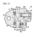
- the fluid path 86 is joined to a fluid path 87 in a lower side, extending so as to be substantially orthogonal to the fluid path 86, through the pressure control valve 68 located in the vertical direction (refer to FIG. 12).
- the fluid path 87 extends forward from an area in which the pressure control valve 68 is provided so as to reach under the fluid chamber 74, and communicates with the fluid path 88 whose front end is approximately orthogonal to the fluid path 87.
- check valves 89 and 89 are intermediately installed, respectively.
- both right and left ends of the fluid path 87 rise upward and communicate with the above-mentioned right and left fluid chambers 74a and 74b respectively.
- the fluid path 88 acts as a fluid path in an entrance side to which the once exhausted hydraulic fluid is returned again to the fluid chambers 74a and 74b.
- the fluid path 87 where the above-mentioned electric pressure control valve 68 is intermediately installed becomes a connecting fluid path which makes the fluid paths in the entrance side and discharge side in view of the fluid chamber communicate.
- the fluid paths 83, 84, 86, 87, and 88 are formed in an upper portion and in a lower portion, i.e., two steps, of the body 7 of the housing 52.
- Both the check valves 85 and 89 have the same structure.
- a valve body 85a not only a valve seat 85b is provided, but also a ball 85c is contained.
- the ball 85c is suitably urged by a spring 85d so as to abut against the valve seat 85b.
- the check valve 85 prevents the flow of the fluid in the reverse direction.
- the check valve 85 prevents the flow of the hydraulic fluid in the reverse direction.
- the check valve 89 prevents the flow of the hydraulic fluid in the reverse direction.
- the pressure control valve 68 varies a damping force of the steering damper 51.
- the pressure control valve 68 not only is a valve seat 68b provided in a valve body 68a, but also a poppet 68c is contained so as to face the valve seat 68b.
- the poppet 68c is suitably urged by a spring 68d intermediately installed between a base spring seat of the poppet 68c, and the valve seat 68b so as to depart from the valve seat 68b.
- An upper end of a push rod 68e is inserted into a lower edge of the poppet 68c, and a lower edge of the push rod 68e is joined to the linear solenoid 69. Then, pressure adjustment is performed by the energizing operation of the linear solenoid 69 so that the poppet 68c may resist the urging force of the spring 68d for its head to abut against the valve seat 68c.
- a location of the poppet 68c is settled by the differential pressure between the right and left fluid chambers 74a and 74b inside the housing 52 which communicate with spaces of its head and base, the urging force of the spring 68d, and an exciting force of the linear solenoid 69 through the push rod 68e.
- the poppet 68c abuts on the valve seat 68b for the pressure control valve 68 concerned to be in a closed state.
- linear solenoid 69 is controlled by a controller, which is not illustrated, according to vehicle speed or vehicle body acceleration.
- a bypass fluid path 91 is formed between the fluid path 86 and fluid path 87, and a relief valve 92 is intermediately installed in the bypass fluid path 91.
- the relief valve 92 has the structure that not only a valve seat 92b is provided in a valve body 92a, but also a ball 92c is contained, the ball 92c which is energized toward the valve seat 92b with the suitable thrust by the spring 92d.
- the relief valve 92 is moved and opens the valve by the ball 92c departing from a valve seat with resisting the urging force of the spring 92d by the thrust based on the differential pressure when the differential pressure between the fluid path 86 and fluid path 87 becomes a predetermined value or higher. Accordingly, the differential pressure between the fluid path 86 and fluid path 87 is relieved.
- a free piston 93 communicates with the fluid path 88.
- the free piston 93 has the structure of including a cylinder 93a formed with the body 71 integrally, a piston 93c which partitions a reserving section 93b for reserving hydraulic fluid in a front part of the cylinder 93a, and a spring 93d which energizes the piston 93c toward the reserving section.
- the linear solenoid 69 which controls the hydraulic control valve 68 of the steering damper 51 is controlled according to the vehicle speed and vehicle body acceleration which are determined by sensors, not shown, respectively.
- the top bridge 49 rotates in this direction integrally with the steering handle 21, and the motion of the top bridge 49 is transmitted to the shaft 53 of the steering damper main body 51 A through the link mechanism 56.
- the vane 75 also rotates in this direction therewith (F direction in FIG. 11).
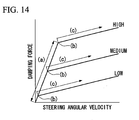
- the pressure of the hydraulic fluid which is filled in the fluid chamber 74b, increases, since the fluid chamber 74b becomes narrow, the hydraulic fluid in the fluid chamber 74b directly moves to the fluid chamber 74a in another side through a gap between the vane 75 and inner circumferential surface which partitions the fluid chamber 74, and the like (indicated by symbol (a) in FIG.
- the pressure control valve 68 is closed. Accordingly, even if some hydraulic fluid pressure is applied from the fluid chamber 74b, the pressure control valve 68 is maintained in the closed state. Because the thrust based on the differential pressure between the right and left fluid chambers 74a and 74b increases gradually with the rise of the steering angular velocity of the steering handle 21, the resultant force of the thrust and urging force of the spring 68d may exceed the exciting force of the linear solenoid 69.
- the poppet 68c departs from a valve seat 68b, and hence, the pressure control valve 68 becomes in the open state (this point is indicated by each symbol (b) in FIG. 14). Then, through the pressure control valve 68 which becomes in the open state, the hydraulic fluid in the fluid path 86 passes along a gap between the valve seat 68b of the pressure control valve 68 and the poppet 68c, and reaches the fluid path 87. Furthermore, it reaches therefrom to the left fluid chamber 74a through the fluid path 88 and check valve 89 (indicated by each symbol (c) in FIG. 14). That is, the hydraulic fluid flows into the fluid chamber 74a continuously from the fluid chamber 74b through the pressure control valve 68 which become in the open state.
- the flow resistance of the hydraulic fluid which flows into the fluid chamber 74a from the fluid chamber 74b generates a damping force which acts on the steering handle 21.
- the flow resistance of the hydraulic fluid acts as a resistance force when turning the steering handle 21, and acts as a resistance force to the momentary turning force acting on the steering handle.
- the increasing rate of the damping force with respect to the steering angular velocity become smaller at a large steering angular velocity than at a small steering angular velocity, or at a large damping force than at a low damping force (i.e., the slope of line (c) in FIG. 14 becomes less than the slope of line (a)).
- the linear solenoid 69 is controlled depending on the vehicle speed. More specifically, the upper limit of the current supplied to the linear solenoid 69 is controlled so as to be high as vehicle speed is increased. Hence, for example, at a high-speed region, the timing when the pressure control valve 68 enters in the open state (each symbol (b) in FIG. 14) is delayed, and furthermore, a larger damping force is exhibited by an increased amount of the exciting force even after entering in the open state. That is, when vehicle speed reaches a high-speed region, a damping force larger than that in a low speed region or a medium speed region is exhibited.
- the hydraulic fluid pressure in one of the right and left fluid chambers 74a and 74b is increased due to some causes during the control operation of the above-mentioned steering damper 51, and thus the differential pressure of the hydraulic fluid between the upstream and downstream of the pressure control valve 68 may become larger than a preset value, the excessively large differential pressure between them is relieved by opening the relief valve 92 so as to allow the hydraulic fluid in the fluid path 86 to flow to the fluid path 87 through the bypass fluid path 91. In this manner, the hydraulic fluid pressure of the one fluid chamber becoming excessively high is prevented beforehand.
- the current value supplied to the linear solenoid 69 is controlled steplessly according to the vehicle speed and vehicle body acceleration (in addition, FIG. 14 shows only three typical cases, that is, high, medium, and low current for the convenience of expression).
- the present invention is not limited to this, and can be applied to a configuration in which the supply current value to the linear solenoid 69 is controlled stepwise.
- the present invention is not limited to this, and it is also possible for the relationship between the steering angular velocity and the damping force of the steering system to not be linear over the entire steering angular velocity region by the relief valve 92 provided in the fluid path communicating with the fluid path 88 in an entrance side to the fluid chamber 74 of the steering damper main body 51 A, and fluid paths 83 and 84 in a discharge side, and an increasing rate of the damping force with respect to the steering angular velocity is set so as to be smaller at a large steering angular velocity than at a small steering angular velocity, or at a large damping force than at a small damping force.
- the relationship between the steering angular velocity and the damping force of the steering system is not linear in a full steering angular velocity region.
- the steering damper is set so that an increasing rate of the damping force with respect to the steering angular velocity of the steering system may become smaller at a large steering angular velocity than at a small steering angular velocity, or at a large damping force than at a small damping force.
- a steering damper includes a steering damper body installed in a steering system of a vehicle, and having a fluid path therein, and a pressure control valve for controlling a damping force in the steering system, and provided in the fluid path, wherein the pressure control valve controls the damping force so that an increasing rate of the damping force with respect to a steering angular velocity when the steering angular velocity is large is lower than that when the steering angular velocity is small.
Applications Claiming Priority (2)
| Application Number | Priority Date | Filing Date | Title |
|---|---|---|---|
| JP2003151263 | 2003-05-28 | ||
| JP2003151263A JP4545392B2 (ja) | 2003-05-28 | 2003-05-28 | ステアリングダンパ |
Publications (3)
| Publication Number | Publication Date |
|---|---|
| EP1481882A2 true EP1481882A2 (de) | 2004-12-01 |
| EP1481882A3 EP1481882A3 (de) | 2007-07-18 |
| EP1481882B1 EP1481882B1 (de) | 2011-08-10 |
Family
ID=33128253
Family Applications (1)
| Application Number | Title | Priority Date | Filing Date |
|---|---|---|---|
| EP04012506A Expired - Fee Related EP1481882B1 (de) | 2003-05-28 | 2004-05-26 | Lenkungsdämpfer |
Country Status (4)
| Country | Link |
|---|---|
| US (1) | US7267350B2 (de) |
| EP (1) | EP1481882B1 (de) |
| JP (1) | JP4545392B2 (de) |
| ES (1) | ES2367792T3 (de) |
Cited By (5)
| Publication number | Priority date | Publication date | Assignee | Title |
|---|---|---|---|---|
| DE102006036135A1 (de) * | 2006-08-01 | 2008-02-07 | Edgar Uden | Lenkungsdämpfer mit veränderbarer Wirkung für Kraftfahrzeuge und andere Fahrzeuge |
| EP2130754A1 (de) * | 2008-06-04 | 2009-12-09 | Yamaha Hatsudoki Kabushiki Kaisha | Lenkungsdämpfersystem und Sattelfahrzeug damit |
| EP2167837A1 (de) * | 2007-06-14 | 2010-03-31 | Öhlins Racing Ab | Hydraulischer rotationsdämpfer für ein fahrzeug |
| ITMI20090904A1 (it) * | 2009-05-21 | 2010-11-22 | Piaggio & C Spa | Metodo di controllo di un ammortizzatore di sterzo elettronicamente modulabile per un veicolo a due ruote ed apparato implementante lo stesso |
| US9409588B2 (en) | 2011-05-05 | 2016-08-09 | Ohlins Racing Ab | Steering damper with active adjustment of damping characteristics |
Families Citing this family (13)
| Publication number | Priority date | Publication date | Assignee | Title |
|---|---|---|---|---|
| US7021433B2 (en) * | 2003-03-20 | 2006-04-04 | Honda Motor Co., Ltd. | Vehicle steering damper, steering damper kit for motorcycle, and motorcycle incorporating same |
| JP4493074B2 (ja) * | 2004-02-05 | 2010-06-30 | 本田技研工業株式会社 | 自動2輪車のステアリングダンパ装置 |
| JP2006226342A (ja) * | 2005-02-16 | 2006-08-31 | Kayaba Ind Co Ltd | バルブ構造 |
| JP4545624B2 (ja) * | 2005-03-31 | 2010-09-15 | 本田技研工業株式会社 | ステアリングダンパ取り付け構造 |
| JP4739969B2 (ja) * | 2006-02-06 | 2011-08-03 | カヤバ工業株式会社 | ロータリダンパ |
| JP4768462B2 (ja) * | 2006-02-06 | 2011-09-07 | カヤバ工業株式会社 | ロータリダンパ |
| JP4750571B2 (ja) * | 2006-02-15 | 2011-08-17 | カヤバ工業株式会社 | ロータリダンパ |
| US7793957B2 (en) * | 2007-06-29 | 2010-09-14 | Kayaba Industry Co., Ltd. | Steering damping device |
| US7970511B2 (en) * | 2008-02-06 | 2011-06-28 | Honda Motor Company, Ltd. | Electronic steering damper systems and vehicles including same |
| US9863450B1 (en) * | 2014-04-16 | 2018-01-09 | Rockwell Collins, Inc. | Hydro-mechanical device with preloaded flow regulating assembly |
| IT201600090140A1 (it) * | 2016-09-06 | 2018-03-06 | Piaggio & C Spa | Gruppo di sterzo di motoveicolo e relativo motoveicolo |
| US10946925B2 (en) * | 2017-12-14 | 2021-03-16 | George John Athanasiou | Multi positional rotary steering damper assembly |
| JP2021162368A (ja) | 2020-03-30 | 2021-10-11 | 株式会社豊田中央研究所 | タイヤ状態量推定装置、タイヤ状態量推定方法及びタイヤ状態量推定プログラム |
Citations (5)
| Publication number | Priority date | Publication date | Assignee | Title |
|---|---|---|---|---|
| JPH0774023B2 (ja) | 1986-07-01 | 1995-08-09 | カヤバ工業株式会社 | 二輪車のステアリングダンパの減衰力制御装置 |
| US5944152A (en) | 1993-10-14 | 1999-08-31 | Vitec Group, Plc | Apparatus mountings providing at least one axis of movement with damping |
| EP1248013A2 (de) | 2001-04-06 | 2002-10-09 | Honda Giken Kogyo Kabushiki Kaisha | Dämpfer für Lenker |
| EP1323625A2 (de) | 2001-12-28 | 2003-07-02 | Honda Giken Kogyo Kabushiki Kaisha | Lenkungsdämpfer |
| EP1459971A2 (de) | 2003-03-20 | 2004-09-22 | HONDA MOTOR CO., Ltd. | Lenkungsdämpfer für Fahrzeug |
Family Cites Families (8)
| Publication number | Priority date | Publication date | Assignee | Title |
|---|---|---|---|---|
| US3907079A (en) * | 1973-10-31 | 1975-09-23 | Hughes Aircraft Co | Viscous fluid damper |
| JPS60219183A (ja) * | 1984-04-13 | 1985-11-01 | ヤマハ発動機株式会社 | 自動二輪車の操向装置 |
| JPH0322586Y2 (de) * | 1985-02-23 | 1991-05-16 | ||
| JPH03239828A (ja) * | 1990-02-13 | 1991-10-25 | Kayaba Ind Co Ltd | ロータリダンパ |
| EP0757644B1 (de) * | 1992-09-18 | 2000-11-29 | Klein Bicycle Corporation | Fahrradaufhängung mit hohem wirkungsgrad |
| JPH0774023A (ja) | 1993-09-01 | 1995-03-17 | Hitachi Ltd | 集積化インダクタおよびそれを用いた弾性表面波装置 |
| JP4640904B2 (ja) * | 2001-09-07 | 2011-03-02 | 本田技研工業株式会社 | ステアリングダンパ装置 |
| US6802519B2 (en) * | 2002-09-09 | 2004-10-12 | Rtt Motorsports, Llc | Steering damper |
-
2003
- 2003-05-28 JP JP2003151263A patent/JP4545392B2/ja not_active Expired - Lifetime
-
2004
- 2004-05-25 US US10/853,847 patent/US7267350B2/en active Active
- 2004-05-26 EP EP04012506A patent/EP1481882B1/de not_active Expired - Fee Related
- 2004-05-26 ES ES04012506T patent/ES2367792T3/es active Active
Patent Citations (5)
| Publication number | Priority date | Publication date | Assignee | Title |
|---|---|---|---|---|
| JPH0774023B2 (ja) | 1986-07-01 | 1995-08-09 | カヤバ工業株式会社 | 二輪車のステアリングダンパの減衰力制御装置 |
| US5944152A (en) | 1993-10-14 | 1999-08-31 | Vitec Group, Plc | Apparatus mountings providing at least one axis of movement with damping |
| EP1248013A2 (de) | 2001-04-06 | 2002-10-09 | Honda Giken Kogyo Kabushiki Kaisha | Dämpfer für Lenker |
| EP1323625A2 (de) | 2001-12-28 | 2003-07-02 | Honda Giken Kogyo Kabushiki Kaisha | Lenkungsdämpfer |
| EP1459971A2 (de) | 2003-03-20 | 2004-09-22 | HONDA MOTOR CO., Ltd. | Lenkungsdämpfer für Fahrzeug |
Cited By (9)
| Publication number | Priority date | Publication date | Assignee | Title |
|---|---|---|---|---|
| DE102006036135A1 (de) * | 2006-08-01 | 2008-02-07 | Edgar Uden | Lenkungsdämpfer mit veränderbarer Wirkung für Kraftfahrzeuge und andere Fahrzeuge |
| DE102006036135B4 (de) * | 2006-08-01 | 2010-07-22 | Edgar Uden | Lenkungsdämpfer mit veränderbarer Wirkung für Kraftfahrzeuge und andere Fahrzeuge mit nur einem gelenkten Vorderrad |
| EP2167837A1 (de) * | 2007-06-14 | 2010-03-31 | Öhlins Racing Ab | Hydraulischer rotationsdämpfer für ein fahrzeug |
| EP2167837A4 (de) * | 2007-06-14 | 2014-05-14 | Hlins Racing Ab | Hydraulischer rotationsdämpfer für ein fahrzeug |
| EP2130754A1 (de) * | 2008-06-04 | 2009-12-09 | Yamaha Hatsudoki Kabushiki Kaisha | Lenkungsdämpfersystem und Sattelfahrzeug damit |
| US8775024B2 (en) | 2008-06-04 | 2014-07-08 | Yamaha Hatsudoki Kabushiki Kaisha | Steering damper system, and a saddle riding type vehicle having the same |
| ITMI20090904A1 (it) * | 2009-05-21 | 2010-11-22 | Piaggio & C Spa | Metodo di controllo di un ammortizzatore di sterzo elettronicamente modulabile per un veicolo a due ruote ed apparato implementante lo stesso |
| EP2256022A1 (de) * | 2009-05-21 | 2010-12-01 | PIAGGIO & C. S.p.A. | Verfahren zur Steuerung einer elektronisch verstellbaren Lenkdämpfer eines zweiradfahrzeugs und dessen Vorrichtung |
| US9409588B2 (en) | 2011-05-05 | 2016-08-09 | Ohlins Racing Ab | Steering damper with active adjustment of damping characteristics |
Also Published As
| Publication number | Publication date |
|---|---|
| US7267350B2 (en) | 2007-09-11 |
| ES2367792T3 (es) | 2011-11-08 |
| US20040239069A1 (en) | 2004-12-02 |
| EP1481882B1 (de) | 2011-08-10 |
| EP1481882A3 (de) | 2007-07-18 |
| JP4545392B2 (ja) | 2010-09-15 |
| JP2004352048A (ja) | 2004-12-16 |
Similar Documents
| Publication | Publication Date | Title |
|---|---|---|
| EP1481882B1 (de) | Lenkungsdämpfer | |
| EP1459971B1 (de) | Lenkungsdämpfer für Fahrzeug | |
| EP1707483B1 (de) | Fahrzeug mit einer Befestigungsstruktur eines Lenkungsdämpfers | |
| JP4640905B2 (ja) | ステアリングダンパ装置 | |
| JP2003237672A (ja) | 自動二輪車用ステアリングダンパー | |
| US7258211B2 (en) | Rotary damper | |
| CN1321857C (zh) | 转向减震器装置 | |
| JP4197592B2 (ja) | ステアリングダンパ装置 | |
| EP1323946B1 (de) | Dämpfer für Lenker | |
| US7559566B2 (en) | Swing arm suspension | |
| JP3836053B2 (ja) | オートバイ枠体 | |
| JP4342981B2 (ja) | ロータリーダンパ | |
| JP4463489B2 (ja) | 自動二輪車におけるステアリングダンパの取付構造 | |
| JP4342820B2 (ja) | 車両用ステアリングダンパ | |
| JP4198497B2 (ja) | 自動二輪車におけるステアリングダンパの取付構造 | |
| JP2004231036A (ja) | ステアリング装置 | |
| JP2004026092A (ja) | 自動二輪車のステアリングダンパー装置 | |
| JP2003175877A (ja) | ステアリング装置 | |
| JP6494682B2 (ja) | 鞍乗り型車両用ステアリングダンパ装置 | |
| JP4142291B2 (ja) | ステアリングダンパ装置 | |
| JP3104573B2 (ja) | サスペンションアーム支持構造 | |
| JP2007223572A (ja) | 緩衝器および自動二輪車 |
Legal Events
| Date | Code | Title | Description |
|---|---|---|---|
| PUAI | Public reference made under article 153(3) epc to a published international application that has entered the european phase |
Free format text: ORIGINAL CODE: 0009012 |
|
| AK | Designated contracting states |
Kind code of ref document: A2 Designated state(s): AT BE BG CH CY CZ DE DK EE ES FI FR GB GR HU IE IT LI LU MC NL PL PT RO SE SI SK TR |
|
| AX | Request for extension of the european patent |
Extension state: AL HR LT LV MK |
|
| PUAL | Search report despatched |
Free format text: ORIGINAL CODE: 0009013 |
|
| AK | Designated contracting states |
Kind code of ref document: A3 Designated state(s): AT BE BG CH CY CZ DE DK EE ES FI FR GB GR HU IE IT LI LU MC NL PL PT RO SE SI SK TR |
|
| AX | Request for extension of the european patent |
Extension state: AL HR LT LV MK |
|
| 17P | Request for examination filed |
Effective date: 20071025 |
|
| AKX | Designation fees paid |
Designated state(s): DE ES FR GB IT |
|
| 17Q | First examination report despatched |
Effective date: 20090702 |
|
| GRAP | Despatch of communication of intention to grant a patent |
Free format text: ORIGINAL CODE: EPIDOSNIGR1 |
|
| GRAS | Grant fee paid |
Free format text: ORIGINAL CODE: EPIDOSNIGR3 |
|
| GRAA | (expected) grant |
Free format text: ORIGINAL CODE: 0009210 |
|
| RAP1 | Party data changed (applicant data changed or rights of an application transferred) |
Owner name: KAYABA INDUSTRY CO., LTD. Owner name: HONDA MOTOR CO., LTD. |
|
| RIN1 | Information on inventor provided before grant (corrected) |
Inventor name: SAKAI, KIYOTAKA Inventor name: NANRI, TAKEHIKO Inventor name: WAKABAYASHI, TAKESHI Inventor name: YAMADA, SHINICHI |
|
| AK | Designated contracting states |
Kind code of ref document: B1 Designated state(s): DE ES FR GB IT |
|
| REG | Reference to a national code |
Ref country code: GB Ref legal event code: FG4D |
|
| REG | Reference to a national code |
Ref country code: DE Ref legal event code: R081 Ref document number: 602004033820 Country of ref document: DE Owner name: KYB CORPORATION, JP Free format text: FORMER OWNERS: HONDA MOTOR CO., LTD., TOKYO, JP; KAYABA INDUSTRY CO., LTD., TOKYO, JP Ref country code: DE Ref legal event code: R081 Ref document number: 602004033820 Country of ref document: DE Owner name: HONDA MOTOR CO., LTD., JP Free format text: FORMER OWNERS: HONDA MOTOR CO., LTD., TOKYO, JP; KAYABA INDUSTRY CO., LTD., TOKYO, JP |
|
| REG | Reference to a national code |
Ref country code: DE Ref legal event code: R096 Ref document number: 602004033820 Country of ref document: DE Effective date: 20111013 |
|
| REG | Reference to a national code |
Ref country code: ES Ref legal event code: FG2A Ref document number: 2367792 Country of ref document: ES Kind code of ref document: T3 Effective date: 20111108 |
|
| PG25 | Lapsed in a contracting state [announced via postgrant information from national office to epo] |
Ref country code: IT Free format text: LAPSE BECAUSE OF FAILURE TO SUBMIT A TRANSLATION OF THE DESCRIPTION OR TO PAY THE FEE WITHIN THE PRESCRIBED TIME-LIMIT Effective date: 20110810 |
|
| PLBE | No opposition filed within time limit |
Free format text: ORIGINAL CODE: 0009261 |
|
| STAA | Information on the status of an ep patent application or granted ep patent |
Free format text: STATUS: NO OPPOSITION FILED WITHIN TIME LIMIT |
|
| 26N | No opposition filed |
Effective date: 20120511 |
|
| REG | Reference to a national code |
Ref country code: DE Ref legal event code: R097 Ref document number: 602004033820 Country of ref document: DE Effective date: 20120511 |
|
| REG | Reference to a national code |
Ref country code: FR Ref legal event code: PLFP Year of fee payment: 12 |
|
| REG | Reference to a national code |
Ref country code: DE Ref legal event code: R082 Ref document number: 602004033820 Country of ref document: DE Representative=s name: WEICKMANN & WEICKMANN PATENTANWAELTE - RECHTSA, DE Ref country code: DE Ref legal event code: R081 Ref document number: 602004033820 Country of ref document: DE Owner name: HONDA MOTOR CO., LTD., JP Free format text: FORMER OWNERS: HONDA MOTOR CO., LTD., TOKYO, JP; KAYABA INDUSTRY CO., LTD., TOKYO, JP Ref country code: DE Ref legal event code: R081 Ref document number: 602004033820 Country of ref document: DE Owner name: KYB CORPORATION, JP Free format text: FORMER OWNERS: HONDA MOTOR CO., LTD., TOKYO, JP; KAYABA INDUSTRY CO., LTD., TOKYO, JP Ref country code: DE Ref legal event code: R082 Ref document number: 602004033820 Country of ref document: DE Representative=s name: WEICKMANN & WEICKMANN PATENT- UND RECHTSANWAEL, DE |
|
| REG | Reference to a national code |
Ref country code: ES Ref legal event code: PC2A Owner name: KYB CORPORATION Effective date: 20160226 |
|
| REG | Reference to a national code |
Ref country code: FR Ref legal event code: PLFP Year of fee payment: 13 |
|
| REG | Reference to a national code |
Ref country code: FR Ref legal event code: CD Owner name: KYB CORPORATION, JP Effective date: 20160321 Ref country code: FR Ref legal event code: CD Owner name: HONDA MOTOR CO., LTD., JP Effective date: 20160321 Ref country code: FR Ref legal event code: CA Effective date: 20160321 |
|
| PG25 | Lapsed in a contracting state [announced via postgrant information from national office to epo] |
Ref country code: IT Free format text: LAPSE BECAUSE OF FAILURE TO SUBMIT A TRANSLATION OF THE DESCRIPTION OR TO PAY THE FEE WITHIN THE PRESCRIBED TIME-LIMIT Effective date: 20120526 |
|
| PG25 | Lapsed in a contracting state [announced via postgrant information from national office to epo] |
Ref country code: IT Free format text: LAPSE BECAUSE OF FAILURE TO SUBMIT A TRANSLATION OF THE DESCRIPTION OR TO PAY THE FEE WITHIN THE PRESCRIBED TIME-LIMIT Effective date: 20120526 |
|
| PGRI | Patent reinstated in contracting state [announced from national office to epo] |
Ref country code: IT Effective date: 20161116 |
|
| REG | Reference to a national code |
Ref country code: FR Ref legal event code: PLFP Year of fee payment: 14 |
|
| REG | Reference to a national code |
Ref country code: FR Ref legal event code: PLFP Year of fee payment: 15 |
|
| PGFP | Annual fee paid to national office [announced via postgrant information from national office to epo] |
Ref country code: SE Payment date: 20190523 Year of fee payment: 18 Ref country code: ES Payment date: 20190604 Year of fee payment: 16 |
|
| PGFP | Annual fee paid to national office [announced via postgrant information from national office to epo] |
Ref country code: FR Payment date: 20190410 Year of fee payment: 16 |
|
| PGFP | Annual fee paid to national office [announced via postgrant information from national office to epo] |
Ref country code: GB Payment date: 20190522 Year of fee payment: 16 |
|
| GBPC | Gb: european patent ceased through non-payment of renewal fee |
Effective date: 20200526 |
|
| PG25 | Lapsed in a contracting state [announced via postgrant information from national office to epo] |
Ref country code: GB Free format text: LAPSE BECAUSE OF NON-PAYMENT OF DUE FEES Effective date: 20200526 Ref country code: FR Free format text: LAPSE BECAUSE OF NON-PAYMENT OF DUE FEES Effective date: 20200531 |
|
| REG | Reference to a national code |
Ref country code: DE Ref legal event code: R082 Ref document number: 602004033820 Country of ref document: DE Representative=s name: WEICKMANN & WEICKMANN PATENT- UND RECHTSANWAEL, DE Ref country code: DE Ref legal event code: R081 Ref document number: 602004033820 Country of ref document: DE Owner name: HONDA MOTOR CO., LTD., JP Free format text: FORMER OWNERS: HONDA MOTOR CO., LTD., TOKYO, JP; KYB CORPORATION, TOKIO, JP |
|
| PGFP | Annual fee paid to national office [announced via postgrant information from national office to epo] |
Ref country code: DE Payment date: 20210427 Year of fee payment: 18 |
|
| REG | Reference to a national code |
Ref country code: ES Ref legal event code: FD2A Effective date: 20211004 |
|
| PG25 | Lapsed in a contracting state [announced via postgrant information from national office to epo] |
Ref country code: ES Free format text: LAPSE BECAUSE OF NON-PAYMENT OF DUE FEES Effective date: 20200527 |
|
| REG | Reference to a national code |
Ref country code: DE Ref legal event code: R119 Ref document number: 602004033820 Country of ref document: DE |
|
| PG25 | Lapsed in a contracting state [announced via postgrant information from national office to epo] |
Ref country code: IT Free format text: LAPSE BECAUSE OF FAILURE TO SUBMIT A TRANSLATION OF THE DESCRIPTION OR TO PAY THE FEE WITHIN THE PRESCRIBED TIME-LIMIT Effective date: 20200526 |
|
| PG25 | Lapsed in a contracting state [announced via postgrant information from national office to epo] |
Ref country code: DE Free format text: LAPSE BECAUSE OF NON-PAYMENT OF DUE FEES Effective date: 20221201 |