EP1479787B2 - Sinter magnet made from rare earth-iron-boron alloy powder for magnet - Google Patents
Sinter magnet made from rare earth-iron-boron alloy powder for magnet Download PDFInfo
- Publication number
- EP1479787B2 EP1479787B2 EP03737488.1A EP03737488A EP1479787B2 EP 1479787 B2 EP1479787 B2 EP 1479787B2 EP 03737488 A EP03737488 A EP 03737488A EP 1479787 B2 EP1479787 B2 EP 1479787B2
- Authority
- EP
- European Patent Office
- Prior art keywords
- alloy
- rare
- earth
- iron
- magnet
- Prior art date
- Legal status (The legal status is an assumption and is not a legal conclusion. Google has not performed a legal analysis and makes no representation as to the accuracy of the status listed.)
- Expired - Lifetime
Links
Images


Classifications
-
- C—CHEMISTRY; METALLURGY
- C22—METALLURGY; FERROUS OR NON-FERROUS ALLOYS; TREATMENT OF ALLOYS OR NON-FERROUS METALS
- C22C—ALLOYS
- C22C38/00—Ferrous alloys, e.g. steel alloys
- C22C38/005—Ferrous alloys, e.g. steel alloys containing rare earths, i.e. Sc, Y, Lanthanides
-
- C—CHEMISTRY; METALLURGY
- C22—METALLURGY; FERROUS OR NON-FERROUS ALLOYS; TREATMENT OF ALLOYS OR NON-FERROUS METALS
- C22C—ALLOYS
- C22C1/00—Making non-ferrous alloys
- C22C1/04—Making non-ferrous alloys by powder metallurgy
- C22C1/0433—Nickel- or cobalt-based alloys
- C22C1/0441—Alloys based on intermetallic compounds of the type rare earth - Co, Ni
-
- C—CHEMISTRY; METALLURGY
- C22—METALLURGY; FERROUS OR NON-FERROUS ALLOYS; TREATMENT OF ALLOYS OR NON-FERROUS METALS
- C22C—ALLOYS
- C22C38/00—Ferrous alloys, e.g. steel alloys
- C22C38/002—Ferrous alloys, e.g. steel alloys containing In, Mg, or other elements not provided for in one single group C22C38/001 - C22C38/60
-
- C—CHEMISTRY; METALLURGY
- C22—METALLURGY; FERROUS OR NON-FERROUS ALLOYS; TREATMENT OF ALLOYS OR NON-FERROUS METALS
- C22C—ALLOYS
- C22C38/00—Ferrous alloys, e.g. steel alloys
- C22C38/06—Ferrous alloys, e.g. steel alloys containing aluminium
-
- C—CHEMISTRY; METALLURGY
- C22—METALLURGY; FERROUS OR NON-FERROUS ALLOYS; TREATMENT OF ALLOYS OR NON-FERROUS METALS
- C22C—ALLOYS
- C22C38/00—Ferrous alloys, e.g. steel alloys
- C22C38/10—Ferrous alloys, e.g. steel alloys containing cobalt
-
- C—CHEMISTRY; METALLURGY
- C22—METALLURGY; FERROUS OR NON-FERROUS ALLOYS; TREATMENT OF ALLOYS OR NON-FERROUS METALS
- C22C—ALLOYS
- C22C38/00—Ferrous alloys, e.g. steel alloys
- C22C38/16—Ferrous alloys, e.g. steel alloys containing copper
-
- H—ELECTRICITY
- H01—ELECTRIC ELEMENTS
- H01F—MAGNETS; INDUCTANCES; TRANSFORMERS; SELECTION OF MATERIALS FOR THEIR MAGNETIC PROPERTIES
- H01F1/00—Magnets or magnetic bodies characterised by the magnetic materials therefor; Selection of materials for their magnetic properties
- H01F1/01—Magnets or magnetic bodies characterised by the magnetic materials therefor; Selection of materials for their magnetic properties of inorganic materials
- H01F1/03—Magnets or magnetic bodies characterised by the magnetic materials therefor; Selection of materials for their magnetic properties of inorganic materials characterised by their coercivity
- H01F1/032—Magnets or magnetic bodies characterised by the magnetic materials therefor; Selection of materials for their magnetic properties of inorganic materials characterised by their coercivity of hard-magnetic materials
- H01F1/04—Magnets or magnetic bodies characterised by the magnetic materials therefor; Selection of materials for their magnetic properties of inorganic materials characterised by their coercivity of hard-magnetic materials metals or alloys
- H01F1/047—Alloys characterised by their composition
- H01F1/053—Alloys characterised by their composition containing rare earth metals
- H01F1/055—Alloys characterised by their composition containing rare earth metals and magnetic transition metals, e.g. SmCo5
- H01F1/057—Alloys characterised by their composition containing rare earth metals and magnetic transition metals, e.g. SmCo5 and IIIa elements, e.g. Nd2Fe14B
- H01F1/0571—Alloys characterised by their composition containing rare earth metals and magnetic transition metals, e.g. SmCo5 and IIIa elements, e.g. Nd2Fe14B in the form of particles, e.g. rapid quenched powders or ribbon flakes
- H01F1/0575—Alloys characterised by their composition containing rare earth metals and magnetic transition metals, e.g. SmCo5 and IIIa elements, e.g. Nd2Fe14B in the form of particles, e.g. rapid quenched powders or ribbon flakes pressed, sintered or bonded together
- H01F1/0577—Alloys characterised by their composition containing rare earth metals and magnetic transition metals, e.g. SmCo5 and IIIa elements, e.g. Nd2Fe14B in the form of particles, e.g. rapid quenched powders or ribbon flakes pressed, sintered or bonded together sintered
-
- H—ELECTRICITY
- H01—ELECTRIC ELEMENTS
- H01F—MAGNETS; INDUCTANCES; TRANSFORMERS; SELECTION OF MATERIALS FOR THEIR MAGNETIC PROPERTIES
- H01F41/00—Apparatus or processes specially adapted for manufacturing or assembling magnets, inductances or transformers; Apparatus or processes specially adapted for manufacturing materials characterised by their magnetic properties
- H01F41/02—Apparatus or processes specially adapted for manufacturing or assembling magnets, inductances or transformers; Apparatus or processes specially adapted for manufacturing materials characterised by their magnetic properties for manufacturing cores, coils, or magnets
- H01F41/0253—Apparatus or processes specially adapted for manufacturing or assembling magnets, inductances or transformers; Apparatus or processes specially adapted for manufacturing materials characterised by their magnetic properties for manufacturing cores, coils, or magnets for manufacturing permanent magnets
- H01F41/0266—Moulding; Pressing
-
- H—ELECTRICITY
- H01—ELECTRIC ELEMENTS
- H01F—MAGNETS; INDUCTANCES; TRANSFORMERS; SELECTION OF MATERIALS FOR THEIR MAGNETIC PROPERTIES
- H01F41/00—Apparatus or processes specially adapted for manufacturing or assembling magnets, inductances or transformers; Apparatus or processes specially adapted for manufacturing materials characterised by their magnetic properties
- H01F41/02—Apparatus or processes specially adapted for manufacturing or assembling magnets, inductances or transformers; Apparatus or processes specially adapted for manufacturing materials characterised by their magnetic properties for manufacturing cores, coils, or magnets
- H01F41/0253—Apparatus or processes specially adapted for manufacturing or assembling magnets, inductances or transformers; Apparatus or processes specially adapted for manufacturing materials characterised by their magnetic properties for manufacturing cores, coils, or magnets for manufacturing permanent magnets
- H01F41/0273—Imparting anisotropy
-
- B—PERFORMING OPERATIONS; TRANSPORTING
- B22—CASTING; POWDER METALLURGY
- B22F—WORKING METALLIC POWDER; MANUFACTURE OF ARTICLES FROM METALLIC POWDER; MAKING METALLIC POWDER; APPARATUS OR DEVICES SPECIALLY ADAPTED FOR METALLIC POWDER
- B22F2998/00—Supplementary information concerning processes or compositions relating to powder metallurgy
- B22F2998/10—Processes characterised by the sequence of their steps
-
- B—PERFORMING OPERATIONS; TRANSPORTING
- B22—CASTING; POWDER METALLURGY
- B22F—WORKING METALLIC POWDER; MANUFACTURE OF ARTICLES FROM METALLIC POWDER; MAKING METALLIC POWDER; APPARATUS OR DEVICES SPECIALLY ADAPTED FOR METALLIC POWDER
- B22F2999/00—Aspects linked to processes or compositions used in powder metallurgy
Definitions
- the present invention relates to a rare-earth-iron-boron based alloy, a sintered magnet, and methods of making them.
- a rare-earth-iron-boron based rare-earth magnet (which will be sometimes referred to herein as an "R-Fe-B based magnet”) is atypical high-performance permanent magnet, has astructu re including, as a main phase, an R 2 Fe 14 B-type crystalline phase, which is a ternary tetragonal compound, and exhibits excellent magnet performance.
- R 2 Fe 14 B R is at least one element selected from the group consisting of the rare-earth elements and yttrium and portions of Fe and B may be replaced with other elements.
- R-Fe-B based magnets are roughly classifiable into sintered magnets and bonded magnets.
- a sintered magnet is produced by compacting a fine powder of an R-Fe-B based magnet alloy (with a mean particle size of several ⁇ m) with a press machine and then sintering the resultant compact.
- a bonded magnet is usually produced by compacting a compound of a powder of an R-Fe-B based magnet alloy (with particle sizes of about 100 ⁇ m) and a binder resin within a press machine.
- a powder for use to produce such an R-Fe-B based magnet is made by pulverizing an R-Fe-B based magnet alloy.
- an R-Fe-B based magnet alloy has been made either by an ingot process using a die casting technique or by a strip casting process for rapidly cooling a molten alloy with a chill roller.
- the molten alloy is rapidly cooled and solidified by a chill roller, for example.
- the resultant structure can have a desired small grain size.
- a rapidly solidified alloy in which low-melting grain boundary phases to be liquid phases during the sintering process are distributed uniformly and finely, can be obtained. If those grain boundary phases are distributed uniformly and finely in the alloy, then main and grain boundary phases are highly likely to be in contact with each other in the powder particles obtained by pulverizing the alloy. Thus, the grain boundary phases turn into liquid phases smoothly in the sintering process, thereby advancing the sintering process quickly.
- the sintering temperature can be lowered, the sintering time can be shortened, and a sintered magnet exhibiting high coercivity can be obtained with the excessive growth of crystal grains minimized.
- almost no ⁇ -Fe is crystallized in the rapidly solidified alloy, and therefore, there is no longer any need to carry out the solution treatment.
- the structure is so fine that it is difficult to finely pulverize the respective powder particles to single crystalline grains. If the powder particles are polycrystalline, then the degree of magnetic anisotropy is low. In that case, even if the powder particles are aligned, compressed and compacted under a magnetic field, a desired sintered magnet, in which the main phase has been aligned to such a degree as to achieve a high remanence, cannot be produced.
- Dy has often been added to the material alloy.
- Dy is a rare-earth element, which has the effect of increasing the magnetic anisotropy of an R 2 Fe 14 B phase that is the main phase of an R-Fe-B based sintered magnet.
- Dy is an element of which the supply is very limited. Accordingly, if electric cars are popularized so much in the near future as to generate higher and higher demand for refractory magnets for use in a motor for an electric car, for example, then the resources of Dy will be on the verge of being exhausted soon and there will be a deep concern about a steep rise in material cost.
- a heavy rare-earth element such as Dy cannot contribute to improving the magnet performance unless that element is included in the main phase as disclosed in JP-A-07-122413 , EP-A2-994493 or in JP-A-08-013078 If the rapid cooling rate of the molten alloy is sufficiently low, Dy tends to be absorbed into, and settled in, the main phase. However, if the cooling rate is relatively high as in the strip casting process, then Dy will not be allowed enough time to diffuse from the grain boundary portions into the main phase while the molten alloy is being solidified. To avoid these problems, a method of condensing Dy in the main phase by lowering the cooling rate of the molten alloy may be adopted. But if the molten alloy were cooled at a decreased rate, then the crystal grains would increase their sizes too much and ⁇ -Fe should be produced as already described for the ingot alloy.
- an object of the present invention is to provide a rare-earth-iron-boron based alloy powder, in which a heavy rare-earth element such as Dy is present at a higher concentration in the main phase than in the grain boundary phases and which can be sintered easily, and a method of making such an alloy powder.
- Another object of the present invention is to provide a material alloy for the powder, a sintered magnet made from the powder, and methods of making them.
- a rare-earth-iron-boron based magnet alloy disclosed in claim 1, according to the present invention includes, as a main phase, a plurality of R 2 Fe 14 B type crystals (where R is at least one element selected from the group consisting of the rare-earth elements and yttrium) in which rare-earth-rich phases are dispersed.
- the main phase includes Dy and/or Tb at a higher concentration than a grain boundary phase does.
- the alloy includes 2.5 mass% to 15 mass% of Dy and/or Tb.
- the ratio of Dy and/or Tb to the main phase is at least 1.03 times as high as the ratio of Dy and/or Tb to the overall alloy.
- the alloy includes at most 5 vol% of ⁇ -Fe phase.
- the alloy includes 27
- the alloy includes 27 mass% to 35 mass% of the rare-earth element.
- a rare-earth-iron-boron based magnet alloy powder according to the present invention is obtained by pulverizing any of the alloys described above.
- a sintered magnet according to the present invention is made from the rare-earth-iron-boron based magnet alloy powder described above.
- a method of making a rare-earth-iron-boron based magnet alloy as disclosed in claim 6, according to the present invention includes the steps of: preparing a melt of a rare-earth-iron-boron based alloy; and making a solidified alloy by quenching the melt.
- the step of making the solidified alloy includes the step of forming a solidified alloy layer, including, as a main phase, a plurality of R 2 Fe 14 B-type crystals (where R is at least one element selected from the group consisting of the rare-earth elements and yttrium) in which rare-earth-rich phases are dispersed, by quenching the melt through contact with a cooling member.
- the main phase includes Dy and/or Tb at a higher concentration than a grain boundary phase does.
- the alloy includes 2.5 mass% to 15 mass% of Dy and/or Tb.
- the ratio of Dy and/or Tb to the main phase is at least 1.03 times as high as the ratio of Dy and/or Tb to the overall alloy.
- the step of forming the solidified alloy layer includes forming a first texture layer in contact with the cooling member and then further feeding the melt onto the first texture layer to grow the R 2 Fe 14 B-type crystals on the first texture layer, thereby forming a second texture layer thereon.
- the melt is quenched at a rate of 10 °C /s to 1,000 °C/s and at a supercooling temperature of 100 °C to 300 °C.
- the melt is quenched at a rate of 1 °C/s to 500 °C/s.
- the cooling rate of the molten alloy while the second texture layer is being formed is lower than that of the molten alloy while the first texture layer is being formed.
- the R 2 Fe 14 B-type crystals have an average minor-axis size of at least 20 ⁇ m and an average major-axis size of at least 100 ⁇ m.
- the rare-earth-rich phases are dispersed at an average interval of 10 ⁇ m or less in the R 2 Fe 14 B-type crystals.
- the solidified alloy includes at most 5 vol% of ⁇ -Fe phase.
- the rare-earth element included in the solidified alloy has a concentration of 27 mass% to 35 mass%.
- the solidified alloy layer is formed by a centrifugal casting process.
- a method of making a magnet powder for a sintered magnet according to the present invention includes the steps of: preparing the rare-earth-iron-boron based magnet alloy by any of the methods described above; and pulverizing the alloy.
- a method for producing a sintered magnet according to the present invention includes the steps of: preparing the rare-earth-iron-boron based magnet alloy powder described above; compressing the powder under an aligning magnetic field to make a compact; and sintering the compact.
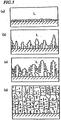
- the present inventors estimated concentration distributions of Dy in rare-earth-iron-boron based magnet alloys with various textures and structures. As a result, we discovered that Dy was present at a higher concentration in the main phase (i.e., R 2 Fe 14 B type crystals) than in the grain boundary phase in the rare-earth-iron-boron based magnet alloy having a structure such as that shown in FIG. 1(d)
- FIG. 1(d) schematically illustrates the structure of a rare-earth-iron-boron based magnet alloy according to the present invention.
- This alloy has a structure in which very small rare-earth-rich phases (shown as black dotted regions in FIG. 1(d) ) are dispersed in relatively coarse columnar crystals.
- Such an alloy including a plurality of columnar crystals, in which the rare-earth-rich phases are dispersed, can be formed by cooling and solidifying a melt of a rare-earth-iron-boron based alloy through contact with a cooling member.
- the composition of the alloy is characterized by R1 x1 R2 x2 T 100-x1-n2-y-z Q y M z (in mass percentages) where R1 is at least one element selected from the group consisting of the rare-earth elements (except R2) and yttrium, T is Fe and/or Co, Q is at least one element selected from the group consisting of B (boron) and C (carbon), R2 is at least one element selected from the group consisting of Dy and Tb, M is at least one element selected from the group consisting of Al, Ti, V, Cr, Mn, Ni, Cu, Zn, Ga, Zr, Nb, Mo, In, Sn, Hf, Ta, W and Pb, and a portion of B may be replaced with N, Si, P and/or S, then 27 ⁇ x1 +x2+ x2 ⁇ 35, 0. 95 ⁇ y ⁇ 1.05, 2.5 ⁇ x2 ⁇ 15 and 0.1 ⁇ z ⁇ 2 (where x,
- the molten alloy L is brought into contact with a cooling member (e.g., a copper chill plate or chill roller), thereby forming a thin first texture layer, including very small primary crystals (of R 2 Fe 14 B), on its side in contact with the cooling member.
- a cooling member e.g., a copper chill plate or chill roller
- the molten alloy L is further fed onto the first texture layer, thereby growing columnar crystals (i.e., R 2 Fe 14 B type crystals) on the first texture layer (see FIG. 1(b) ).
- columnar crystals are formed by continuously feeding the molten alloy but cooling the molten alloy at a lower cooling rate than the initial one.
- the solidification advances before the rare-earth element, included in the molten alloy supplied relatively slowly, diffuses and reaches the grain boundary of those underlying coarse columnar crystals, thus rapidly growing the columnar crystals in which the rare-earth-rich phases are dispersed.
- the cooling rate relatively high while primary crystals are being formed during an early stage of the solidification process and by slowing down the cooling rate during the subsequent crystal growth, the second texture layer, including excessively large columnar crystals, can be obtained in the end as shown in FIG. 1(d) .
- the second texture layer is cooled on the high-temperature first texture layer that has just been solidified. Accordingly, just by controlling the melt feeding rate, the cooling rate of the second texture layer can be set lower than that of the first texture layer without using any special means.
- the molten alloy is cooled at a rate of 10 °C/s to 1,000 °C/s and at a supercooling temperature of 100 °C to 300 °C.
- the supercooling can minimize the nucleation of the Fe primary crystals.
- the molten alloy is cooled at a rate of 1 °C/s to 500 °C/s while being fed continuously.
- the cooling rate is adjusted according to the rate of feeding the melt onto the cooling member.
- the melt is preferably constantly fed little by little onto a cooling member (such as a casting mold).
- a cooling process of scattering or atomizing droplets of the melt is preferably carried out.
- a method of atomizing a melt flow by blowing a gas jet against it or a method of scattering the droplets with centrifugal force may be adopted.
- Another point in the melt quenching method of the present invention is to collect the produced melt droplets on the cooling member at a high yield (i.e., use the droplets efficiently enough to make a solidified alloy).
- a method of blowing the melt droplets onto a flat-plate cooling member or a water-cooled mold with a gas spray or a method of scattering the melt droplets againstthe inner walls of a rotating cylindrical drum-like cooling member i.e., a centrifugal casting process
- a method of producing the melt droplets by a rotating electrode method and depositing them on the cooling member may also be adopted.
- the point is to create crystal nuclei in the areas to contact with the cooling member and to feed a molten alloy thereon relatively slowly.
- the special structure described above can be formed with an adequate balance struck between the quantity of heat to be dissipated during the cooling process and the melt feeding rate.
- large columnar crystals with an average minor-axis size of 20 ⁇ m or more and an average major-axis size of 100 ⁇ m or more can be grown.
- the rare-earth-rich phases, dispersed in the columnar crystals preferably have an average interval of 10 ⁇ m or less.
- No solidified alloy with such a texture and structure could be obtained by any conventional method such as a strip casting process or an alloy ingot process.
- a solidified alloy to be a rare-earth-iron-boron magnet alloy (which will be simply referred to herein as a "solidified alloy") by a conventional process.
- a strip casting process results in a relatively high cooling rate. Accordingly, a molten alloy L, having contacted with the outer surface of a cooling member such as a chill roller that is rotating at a high speed, is rapidly cooled and solidified from its contact surface. To achieve a high cooling rate, the amount of the molten alloy L needs to be decreased. Also, considering the mechanism of the strip caster, the molten alloy cannot be supplied sequentially. Accordingly, the thickness of the molten alloy L on the cooling member does not increase, but remains substantially constant, throughout the quenching process.
- the crystal growth advances rapidly from the surface contacting with the cooling member. Since the cooling rate is high, the minor-axis sizes of the columnar crystals are small as shown in FIGS. 2(a) through 2(c) , and the resultant solidified alloy has a fine structure.
- the rare-earth-rich phases are not present inside of the columnar texture but are dispersed on the grain boundary.
- the crystal grains have such small sizes that regions with aligned crystal orientation are small. Accordingly, the magnetic anisotropy of the respective powder particles decrease.
- FIGS. 3(a) through 3(d) how crystals grow in a conventional ingot process.
- An ingot process results in a relatively low cooling rate. Accordingly, a molten alloy L, having contacted with a cooling member, is slowly cooled and solidified from that contact surface. Inside of the still molten alloy L, first, Fe primary crystals are produced on the surface contacting with the cooling member and then dendritic crystals of Fe are going to grow as shown in FIGS. 3(b) and 3(c) .
- An R 2 Fe 14 B type crystalline phase is finally formed by a peritectic reaction but still includes some ⁇ -Fe phases that would deteriorate the magnet performance.
- the solidified alloy has a coarse structure and includes more than 5 vol% of big ⁇ -Fe phases.
- a homogenizing process needs to be carried out. Specifically, by diffusing and eliminating the ⁇ -Fe and R 2 Fe 17 phases in the ingot alloy as much as possible, the resultant structure should be made to consist essentially of the R 2 Fe 14 B and R-rich phases only.
- the homogenizing heat treatment is carried out at a temperature of 1,100 °C to 1,200 °C for 1 to 48 hours within either an inert atmosphere (except a nitrogen atmosphere) or a vacuum. Such a homogenizing treatment adversely increases the manufacturing cost.
- the mole fraction of the rare-earth element included in the material alloy needs to be sufficiently greater than that defined by stoichiometry.
- the mole fraction of the rare-earth element is increased, then the remanence of the resultant magnet will decrease and the corrosion resistance thereof will deteriorate, which are problems.
- the rare-earth-iron-boron based magnet alloy for use in the present invention includes a rare-earth element at a mole fraction close to that defined by stoichiometry, but is less likely to produce ⁇ -Fe, which is advantageous. Accordingly, the rare-earth content can be reduced than that of the conventional process. Also, the alloy for use in the present invention has a metallographic structure including columnar crystals in which the rare-earth-rich phases are dispersed. For that reason, when the alloy is pulverized into powder particles, rare-earth-rich phases to turn into liquid phases easily are more likely to appear on the surface of the powder particles.
- the rare-earth-rich phases are finely dispersed in the columnar crystals, and therefore, the probability of losing the rare-earth-rich phases as superfine powder in the pulverizing process decreases, too.
- Dy and Tb added are likely to be concentrated in the main phase rather than on the grain boundary as described above. This is because the cooling rate of the molten alloy is lower than that achieved by the strip casting process and Dy and Tb are introduced into the main phase more easily.
- the concentration of Dy or Tb which is one of rare natural resources, is defined to fall within the range of 2.5 mass% to 15 mass%, the effects achieved by that addition are comparable to a situation where the concentration of Dy or Tb is set to 3.0 mass% to 16 mass% in a conventional strip-cast alloy.
- the powder can be sintered more efficiently, the rare natural resource such as Dy can function more effectively, and a sintered magnet with excellent coercivity can be provided at a reduced cost.
- the concentration of the rare-earth element can be within the range of 27 mass% to 35 mass% and the ⁇ -Fe phase to be included in the as-cast solidified alloy yet to be thermally treated can be reduced to 5 vol% or less. As a result, the solidified alloy no longer needs to be thermally treated unlike the conventional ingot alloy.
- the respective powder particles become polycrystalline much less often than the alloy powder prepared by a normal rapid cooling process, and achieves high magnetic anisotropy, thus making the resultant sintered magnet magnetizable very easily.
- the powder can exhibit increased flowability.
- the overall surface area of the powder particles decreases with respect to a unit mass, and therefore, the degree of activity of the superfine powder to an oxidation reaction decreases. As a result, the amount of the rare-earth elementto be wasted due to the oxidation decreases and the resultant magnet performance deteriorates much less easily.
- the alloy was made by scattering a melt having the composition specified above (at about 1, 300 °C) with a centrifugal force toward the inner surfaces of a rotating cylindrical cooling member and cooling and solidifying the scattered melt on the inner surfaces of the cooling member.
- the strip-cast alloy was obtained by rapidly cooling and solidifying a melt having the composition specified above (at about 1,400 °C) through the contact with the outer surface of a water-cooled chill roller (made of copper) rotating at a peripheral velocity of 1 m/s.
- the resultant rapidly solidified alloy were cast flakes with a thickness of 0.2 mm.
- the ingot-cast alloy was obtained by pouring a melt having the composition specified above (at about 1,450 °C) into a water-cooled iron die and gradually cooling it there.
- the resultant ingot cast alloy had a thickness of about 25 mm.
- Alloys A, B and C obtained by the methods described above were coarsely pulverized by a hydrogen decrepitation process and then finely pulverized with a jet mill.
- the hydrogen decrepitation process was carried out in the following manner. First, the material alloy was loaded into a hydrogen process furnace airtight. The furnace was evacuated and then filled with an H 2 gas at 0.3 MPa, thereby performing a pressuring process (i.e., hydrogen absorption process) for an hour. Thereafter, a vacuum was created again in the hydrogen process furnace and a heat treatment was carried out at 400 °C for three hours in that state, thereby performing a dehydrogenation process of removing excessive hydrogen from the alloy.
- a pressuring process i.e., hydrogen absorption process
- an N 2 gas at 0.6 MPa was used as a pulverizing gas, which had an oxygen concentration of 0.1 vol%.
- Table 2 The numerals in Table 2 represent multiple compositions, each consisting of their associated elements (in mass percentages). More specifically, Table 2 shows the compositions of the material alloy, fine powder and sintered body for each of two powders with different particle sizes that were made from Alloy A, B or C. By checking out the compositions at these stages, the variation in composition before and after the pulverization process can be understood.
- Alloy A of the present invention has a higher Nd concentration and a higher Dy concentration in the fine powder than any other alloy B or C. This means that Nd and Dy included in the alloy are not lost easily during the hydrogen decrepitation process or the fine pulverization process with the jet mill.
- a light rare-earth element such as Nd is present on the grain boundary at a higher concentration than that defined by the stoichiometry of R 2 Fe 14 B type crystals and in the main-phase crystal grains at the concentration defined by the stoichiometry of R 2 Fe 14 B type crystals.
- a heavy rare-earth element such as Dy is broadly distributed in the grain boundary and main phases in Alloy B, in particular.
- the hydrogen decrepitation process makes the alloy easily splitting by swelling the grain boundary portions with a high rare-earth element concentration.
- the superfine powder (with particle sizes of 0.5 ⁇ m or less) produced by the hydrogen decrepitation and fine pulverization processes comes from the grain boundary and includes a lot of Nd and Dy.
- such a superfine powder is removed while the powder is being collected with ajet mill.
- Nd and Dy are lost easily.
- Alloy A when Alloy A is used, the rare-earth-rich phases are dispersed in the main-phase crystal grains with relatively large particle sizes, and therefore, fewer grain boundary phases (i.e., R-rich phases) are present between the columnar crystals. Furthermore, the heavy rare-earth element is hardly present on the grain boundary but is concentrated in the main phase. In view of these considerations, Alloy A has a very small amount of superfine powder and the percentage of Nd and Dy to be lost with the superfine powder decreases significantly during the hydrogen decrepitation process and the fine pulverization process with the jet mill.
- A1 through A6 are sintered magnets made from the powders of Alloy A, which had different mean particle sizes or sintering temperatures
- B1 through B4 are sintered magnets made from the powders of Alloy B
- C1 through C4 are sintered magnets made from the powders of Alloy C.
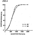
- FIG. 4 is a graph showing the magnetization characteristics.
- the abscissa represents the strength of the magnetizing field applied to the sintered magnet while the ordinate represents the magnetizing percentage.
- the sintered magnet A6 exhibited improved magnetization characteristic as compared with the sintered magnet B2. This is believed to be because Alloy A had a greater main phase size than Alloy B did and a uniform texture, and could be magnetized more easily.
- the atomic number ratio of the rare-earth elements included in each of the sintered magnets described above was calculated on the main phase alone and on the overall sintered magnet.
- the Dy ratio in the main phase is the highest in the sintered magnet made from Alloy A.
- the Dy ratio in the overall sintered magnet is 31.0 but the Dy ratio in the main phase alone is 32.5, which is higher than 31.0 by as much as 4%.
- the Dy concentration in the main phase is higher than that in the grain boundary phase (i.e., Dy is concentrated in the main phase).
- No such phenomenon reads from the results shown in Table 5 for Alloy B. Such a difference was created forthe following reason.
- the ratio of Dy and/or Tb in the main phase is at least 1.03 times as high as that of Dy and/orTb in the overall alloy orsintered magnet.
- the ratio of Dy and/orTb in the main phase is more preferably at least 1.05 times as high as that of Dy and/or Tb in the overall alloy or sintered magnet.
- FIGS. 5 and 6 are polarizing micrographs of a rare-earth-iron-boron based magnet alloy according to the present invention showing atexture cross section near its surface contacting with the cooling member and a texture cross section of a center portion in the thickness direction, respectively.
- the upside shows a cooled surface while the downside shows a heat-dissipating surface (i.e., free surface).
- a very small crystal texture i.e., the first texture layer
- coarse columnar crystals are present in the inner region (i.e., the second texture layer) that is more than about 100 ⁇ m away from the contact surface.
- the alloy cast flake has a thickness of 5 mm to 8 mm, and is mostly composed of the second texture layer consisting essentially of coarse columnar crystals. It should be noted that the boundary between the first and second texture layers is definite somewhere but indefinite elsewhere.
- the present inventors discovered that the higher the concentration of the rare-earth element included, the smaller the crystal grain size of the alloy.
- the FSSS mean particle size thereof is preferably controlled so as to fall within the range of 3.0 ⁇ m to 5.0 ⁇ m.
- Dy and Tb are concentrated in a main phase with a greater size than that of a rapidly solidified alloy, thus increasing the coercivity effectively.
- the main phase included in the resultant solidified alloy has a relatively big size, no ⁇ -Fe is produced and the powder can be sintered sufficiently. As a result, the manufacturing cost of the sintered magnets can be reduced significantly.
Landscapes
- Chemical & Material Sciences (AREA)
- Engineering & Computer Science (AREA)
- Materials Engineering (AREA)
- Mechanical Engineering (AREA)
- Metallurgy (AREA)
- Organic Chemistry (AREA)
- Power Engineering (AREA)
- Manufacturing & Machinery (AREA)
- Inorganic Chemistry (AREA)
- Crystallography & Structural Chemistry (AREA)
- Hard Magnetic Materials (AREA)
- Powder Metallurgy (AREA)
- Manufacturing Cores, Coils, And Magnets (AREA)
- Continuous Casting (AREA)
- Manufacture Of Metal Powder And Suspensions Thereof (AREA)
Applications Claiming Priority (3)
| Application Number | Priority Date | Filing Date | Title |
|---|---|---|---|
| JP2002028207 | 2002-02-05 | ||
| JP2002028207A JP4389427B2 (ja) | 2002-02-05 | 2002-02-05 | 希土類−鉄−硼素系磁石用合金粉末を用いた焼結磁石 |
| PCT/JP2003/001143 WO2003066922A1 (fr) | 2002-02-05 | 2003-02-04 | Aimant constitue par de la poudre d'alliage de bore et de fer des terres rares |
Publications (4)
| Publication Number | Publication Date |
|---|---|
| EP1479787A1 EP1479787A1 (en) | 2004-11-24 |
| EP1479787A4 EP1479787A4 (en) | 2006-01-04 |
| EP1479787B1 EP1479787B1 (en) | 2011-08-03 |
| EP1479787B2 true EP1479787B2 (en) | 2016-07-06 |
Family
ID=27677856
Family Applications (1)
| Application Number | Title | Priority Date | Filing Date |
|---|---|---|---|
| EP03737488.1A Expired - Lifetime EP1479787B2 (en) | 2002-02-05 | 2003-02-04 | Sinter magnet made from rare earth-iron-boron alloy powder for magnet |
Country Status (6)
| Country | Link |
|---|---|
| US (1) | US20060016515A1 (zh) |
| EP (1) | EP1479787B2 (zh) |
| JP (1) | JP4389427B2 (zh) |
| CN (1) | CN1308475C (zh) |
| AU (1) | AU2003244355A1 (zh) |
| WO (1) | WO2003066922A1 (zh) |
Families Citing this family (19)
| Publication number | Priority date | Publication date | Assignee | Title |
|---|---|---|---|---|
| CN100414650C (zh) * | 2001-06-22 | 2008-08-27 | 日立金属株式会社 | 稀土类磁体及其制造方法 |
| JP3997413B2 (ja) * | 2002-11-14 | 2007-10-24 | 信越化学工業株式会社 | R−Fe−B系焼結磁石及びその製造方法 |
| US7199690B2 (en) | 2003-03-27 | 2007-04-03 | Tdk Corporation | R-T-B system rare earth permanent magnet |
| EP1749599B1 (en) * | 2004-04-30 | 2015-09-09 | Hitachi Metals, Ltd. | Methods for producing raw material alloy for rare earth magnet, powder and sintered magnet |
| US20060165550A1 (en) * | 2005-01-25 | 2006-07-27 | Tdk Corporation | Raw material alloy for R-T-B system sintered magnet, R-T-B system sintered magnet and production method thereof |
| US20090035170A1 (en) * | 2007-02-05 | 2009-02-05 | Showa Denko K.K. | R-t-b type alloy and production method thereof, fine powder for r-t-b type rare earth permanent magnet, and r-t-b type rare earth permanent magnet |
| EP2034493B1 (en) * | 2007-05-02 | 2012-12-05 | Hitachi Metals, Ltd. | R-t-b sintered magnet |
| CN101657863B (zh) * | 2007-05-02 | 2012-11-07 | 日立金属株式会社 | R-t-b系烧结磁体 |
| US20100230013A1 (en) * | 2007-12-13 | 2010-09-16 | Showa Denko K.K. | R-t-b alloy, process for production of r-t-b alloy, fine powder for r-t-b rare earth permanent magnets, and r-t-b rare earth permanent magnet |
| JP5093215B2 (ja) * | 2009-11-26 | 2012-12-12 | トヨタ自動車株式会社 | 焼結希土類磁石の製造方法 |
| JP2011159733A (ja) * | 2010-01-29 | 2011-08-18 | Toyota Motor Corp | ナノコンポジット磁石の製造方法 |
| JP5736653B2 (ja) * | 2010-03-09 | 2015-06-17 | Tdk株式会社 | 希土類焼結磁石及び希土類焼結磁石の製造方法 |
| JP2011199069A (ja) * | 2010-03-19 | 2011-10-06 | Tdk Corp | 希土類焼結磁石の製造方法及び希土類焼結磁石用材料 |
| CN103526107B (zh) * | 2012-07-04 | 2017-03-15 | 宁波科宁达工业有限公司 | 制备烧结钕铁硼磁体的方法 |
| EP3011573B1 (en) | 2013-06-17 | 2020-06-10 | Urban Mining Technology Company, LLC | Magnet recycling to create nd-fe-b magnets with improved or restored magnetic performance |
| CN109887697B (zh) * | 2013-11-05 | 2021-07-20 | 株式会社Ihi | 稀土永磁材料以及稀土永磁材料的制造方法 |
| US9336932B1 (en) | 2014-08-15 | 2016-05-10 | Urban Mining Company | Grain boundary engineering |
| CN113563857B (zh) * | 2020-04-29 | 2023-02-24 | 南京公诚节能新材料研究院有限公司 | 一种用于稠油表面张力处理的合金材料及其应用方法 |
| CN112768168B (zh) * | 2020-12-25 | 2023-05-30 | 福建省长汀金龙稀土有限公司 | 一种钕铁硼材料及其制备方法 |
Family Cites Families (18)
| Publication number | Priority date | Publication date | Assignee | Title |
|---|---|---|---|---|
| JPH0663056B2 (ja) * | 1984-01-09 | 1994-08-17 | コルモーゲン コーポレイション | 非焼結永久磁石合金及びその製造方法 |
| CN1012477B (zh) * | 1987-08-19 | 1991-05-01 | 三菱金属株式会社 | 稀土-铁-硼磁体粉末及其制备方法 |
| US5200001A (en) * | 1989-12-01 | 1993-04-06 | Sumitomo Special Metals Co., Ltd. | Permanent magnet |
| JP3121824B2 (ja) * | 1990-02-14 | 2001-01-09 | ティーディーケイ株式会社 | 焼結永久磁石 |
| DE69318998T2 (de) * | 1992-02-15 | 1998-10-15 | Santoku Metal Ind | Legierungsblock für einen Dauermagnet, anisotropes Pulver für einen Dauermagnet, Verfahren zur Herstellung eines solchen und Dauermagneten |
| JPH06124824A (ja) * | 1992-10-28 | 1994-05-06 | Mitsubishi Steel Mfg Co Ltd | 焼結永久磁石 |
| JPH07122413A (ja) * | 1993-10-28 | 1995-05-12 | Hitachi Metals Ltd | 希土類永久磁石およびその製造方法 |
| JP2817624B2 (ja) * | 1994-06-29 | 1998-10-30 | 昭和電工株式会社 | 希土類磁石合金の製造方法 |
| US5858123A (en) * | 1995-07-12 | 1999-01-12 | Hitachi Metals, Ltd. | Rare earth permanent magnet and method for producing the same |
| EP0886284B1 (en) * | 1996-04-10 | 2002-10-23 | Showa Denko Kabushiki Kaisha | Cast alloy used for production of rare earth magnet and method for producing cast alloy and magnet |
| DE69911138T2 (de) * | 1998-10-14 | 2004-07-22 | Hitachi Metals, Ltd. | Gesinterter R-T-B-Dauermagnet |
| US6403024B1 (en) * | 1999-02-19 | 2002-06-11 | Sumitomo Special Metals Co., Ltd. | Hydrogen pulverizer for rare-earth alloy magnetic material powder using the pulverizer, and method for producing magnet using the pulverizer |
| EP1059645B1 (en) * | 1999-06-08 | 2006-06-14 | Shin-Etsu Chemical Co., Ltd. | Thin ribbon of rare earth-based permanent magnet alloy |
| JP3231034B1 (ja) * | 2000-05-09 | 2001-11-19 | 住友特殊金属株式会社 | 希土類磁石およびその製造方法 |
| EP1395381B1 (en) * | 2000-08-31 | 2006-04-05 | Showa Denko K.K. | Centrifugal casting method und centrifugal casting apparatus |
| WO2002079530A2 (en) * | 2001-03-30 | 2002-10-10 | Sumitomo Special Metals Co., Ltd. | Rare earth alloy sintered compact and method of making the same |
| CN100414650C (zh) * | 2001-06-22 | 2008-08-27 | 日立金属株式会社 | 稀土类磁体及其制造方法 |
| CN102511464A (zh) * | 2011-12-12 | 2012-06-27 | 孙名媛 | 一种可夜视蚊香盒 |
-
2002
- 2002-02-05 JP JP2002028207A patent/JP4389427B2/ja not_active Expired - Lifetime
-
2003
- 2003-02-04 EP EP03737488.1A patent/EP1479787B2/en not_active Expired - Lifetime
- 2003-02-04 WO PCT/JP2003/001143 patent/WO2003066922A1/ja active Application Filing
- 2003-02-04 US US10/503,359 patent/US20060016515A1/en not_active Abandoned
- 2003-02-04 CN CNB038033194A patent/CN1308475C/zh not_active Expired - Lifetime
- 2003-02-04 AU AU2003244355A patent/AU2003244355A1/en not_active Abandoned
Non-Patent Citations (1)
| Title |
|---|
| "Magnetic Properties of Nd-Fe-B Magnets alloyed with Dy, Al and Co" A.A. Kiiski et al. Paper No. 19P022t at the Int. Workshop on Rare-Earth Magnets and their Applications, Kyoto, Japan, 16-19 May, 1989 (Proceedings Book: The Society of Non-Traditional Technology, 1-2-8, Tornanomon, Minatoku, Tokyo, 105 Japan), pages 501-507. † |
Also Published As
| Publication number | Publication date |
|---|---|
| WO2003066922A1 (fr) | 2003-08-14 |
| JP4389427B2 (ja) | 2009-12-24 |
| CN1308475C (zh) | 2007-04-04 |
| JP2003226944A (ja) | 2003-08-15 |
| EP1479787A4 (en) | 2006-01-04 |
| AU2003244355A1 (en) | 2003-09-02 |
| CN1628182A (zh) | 2005-06-15 |
| US20060016515A1 (en) | 2006-01-26 |
| EP1479787A1 (en) | 2004-11-24 |
| EP1479787B1 (en) | 2011-08-03 |
Similar Documents
| Publication | Publication Date | Title |
|---|---|---|
| EP1479787B2 (en) | Sinter magnet made from rare earth-iron-boron alloy powder for magnet | |
| EP2388350B1 (en) | Method for producing r-t-b sintered magnet | |
| US7442262B2 (en) | Alloy flake for rare earth magnet, production method thereof, alloy powder for rare earth sintered magnet, rare earth sintered magnet, alloy powder for bonded magnet and bonded magnet | |
| US7892365B2 (en) | Rare earth element-iron-boron alloy, and magnetically anisotropic permanent magnet powder and method for production thereof | |
| EP1780736B1 (en) | R-T-B type alloy, production method of R-T-B type alloy flake, fine powder for R-T-B type rare earth permanent magnet, and R-T-B type rare earth permanent magnet | |
| US8961868B2 (en) | Nanocomposite bulk magnet and process for producing same | |
| US7867343B2 (en) | Rare earth magnet and method for production thereof | |
| US7431070B2 (en) | Rare earth magnet alloy ingot, manufacturing method for the same, R-T-B type magnet alloy ingot, R-T-B type magnet, R-T-B type bonded magnet, R-T-B type exchange spring magnet alloy ingot, R-T-B type exchange spring magnet, and R-T-B type exchange spring bonded magnet | |
| JP3932143B2 (ja) | 磁石の製造方法 | |
| US8182618B2 (en) | Rare earth sintered magnet and method for producing same | |
| JP3724513B2 (ja) | 永久磁石の製造方法 | |
| US20210005380A1 (en) | Method for manufacturing rare earth permanent magnet | |
| JP3693838B2 (ja) | 希土類磁石用合金薄帯、合金微粉末及びそれらの製造方法 | |
| EP1632299B1 (en) | Method for producing rare earth based alloy powder and method for producing rare earth based sintered magnet | |
| JP3693839B2 (ja) | 希土類磁石用合金薄帯、合金微粉末及びそれらの製造方法 | |
| JP2745042B2 (ja) | 希土類−鉄−ボロン系合金薄板、合金粉末及び永久磁石の製造方法 | |
| JP2002088451A (ja) | 希土類磁石およびその製造方法 | |
| JPH0757910A (ja) | 異方性磁性粉末の製造方法および異方性ボンド磁石の製造方法 | |
| JP2004214390A (ja) | 希土類磁石の製造法、希土類磁石用原料合金及び粉末 | |
| JPH09320825A (ja) | 希土類磁石の製造方法 | |
| JPH06132108A (ja) | 希土類−遷移金属−ボロン系磁石の製造方法 |
Legal Events
| Date | Code | Title | Description |
|---|---|---|---|
| PUAI | Public reference made under article 153(3) epc to a published international application that has entered the european phase |
Free format text: ORIGINAL CODE: 0009012 |
|
| 17P | Request for examination filed |
Effective date: 20040825 |
|
| AK | Designated contracting states |
Kind code of ref document: A1 Designated state(s): AT BE BG CH CY CZ DE DK EE ES FI FR GB GR HU IE IT LI LU MC NL PT SE SI SK TR |
|
| AX | Request for extension of the european patent |
Extension state: AL LT LV MK RO |
|
| A4 | Supplementary search report drawn up and despatched |
Effective date: 20051118 |
|
| RIC1 | Information provided on ipc code assigned before grant |
Ipc: C22C 33/02 19680901ALI20051114BHEP Ipc: B22D 1/00 19680901ALI20051114BHEP Ipc: C22C 38/00 19740701AFI20030821BHEP Ipc: B22F 9/10 19800101ALI20051114BHEP |
|
| RAP1 | Party data changed (applicant data changed or rights of an application transferred) |
Owner name: HITACHI METALS, LTD. |
|
| 17Q | First examination report despatched |
Effective date: 20100407 |
|
| GRAP | Despatch of communication of intention to grant a patent |
Free format text: ORIGINAL CODE: EPIDOSNIGR1 |
|
| GRAC | Information related to communication of intention to grant a patent modified |
Free format text: ORIGINAL CODE: EPIDOSCIGR1 |
|
| GRAS | Grant fee paid |
Free format text: ORIGINAL CODE: EPIDOSNIGR3 |
|
| GRAA | (expected) grant |
Free format text: ORIGINAL CODE: 0009210 |
|
| AK | Designated contracting states |
Kind code of ref document: B1 Designated state(s): DE FR NL |
|
| REG | Reference to a national code |
Ref country code: DE Ref legal event code: R096 Ref document number: 60337912 Country of ref document: DE Effective date: 20110929 |
|
| REG | Reference to a national code |
Ref country code: NL Ref legal event code: T3 |
|
| PLBI | Opposition filed |
Free format text: ORIGINAL CODE: 0009260 |
|
| 26 | Opposition filed |
Opponent name: SIEMENS AKTIENGESELLSCHAFT Effective date: 20120502 |
|
| PLAX | Notice of opposition and request to file observation + time limit sent |
Free format text: ORIGINAL CODE: EPIDOSNOBS2 |
|
| REG | Reference to a national code |
Ref country code: DE Ref legal event code: R026 Ref document number: 60337912 Country of ref document: DE Effective date: 20120502 |
|
| PLAF | Information modified related to communication of a notice of opposition and request to file observations + time limit |
Free format text: ORIGINAL CODE: EPIDOSCOBS2 |
|
| PLBB | Reply of patent proprietor to notice(s) of opposition received |
Free format text: ORIGINAL CODE: EPIDOSNOBS3 |
|
| REG | Reference to a national code |
Ref country code: FR Ref legal event code: PLFP Year of fee payment: 14 |
|
| PUAH | Patent maintained in amended form |
Free format text: ORIGINAL CODE: 0009272 |
|
| STAA | Information on the status of an ep patent application or granted ep patent |
Free format text: STATUS: PATENT MAINTAINED AS AMENDED |
|
| 27A | Patent maintained in amended form |
Effective date: 20160706 |
|
| AK | Designated contracting states |
Kind code of ref document: B2 Designated state(s): DE FR NL |
|
| REG | Reference to a national code |
Ref country code: DE Ref legal event code: R102 Ref document number: 60337912 Country of ref document: DE |
|
| REG | Reference to a national code |
Ref country code: NL Ref legal event code: FP |
|
| REG | Reference to a national code |
Ref country code: FR Ref legal event code: PLFP Year of fee payment: 15 |
|
| REG | Reference to a national code |
Ref country code: FR Ref legal event code: PLFP Year of fee payment: 16 |
|
| PGFP | Annual fee paid to national office [announced via postgrant information from national office to epo] |
Ref country code: DE Payment date: 20211230 Year of fee payment: 20 |
|
| PGFP | Annual fee paid to national office [announced via postgrant information from national office to epo] |
Ref country code: NL Payment date: 20220118 Year of fee payment: 20 Ref country code: FR Payment date: 20220118 Year of fee payment: 20 |
|
| REG | Reference to a national code |
Ref country code: DE Ref legal event code: R071 Ref document number: 60337912 Country of ref document: DE |
|
| REG | Reference to a national code |
Ref country code: NL Ref legal event code: MK Effective date: 20230203 |