EP1475655B1 - Vorrichtung zur Ansteuerung des Blickwinkelbereichs, Anzeigevorrichtung und elektronisches Gerät - Google Patents
Vorrichtung zur Ansteuerung des Blickwinkelbereichs, Anzeigevorrichtung und elektronisches Gerät Download PDFInfo
- Publication number
- EP1475655B1 EP1475655B1 EP04252464A EP04252464A EP1475655B1 EP 1475655 B1 EP1475655 B1 EP 1475655B1 EP 04252464 A EP04252464 A EP 04252464A EP 04252464 A EP04252464 A EP 04252464A EP 1475655 B1 EP1475655 B1 EP 1475655B1
- Authority
- EP
- European Patent Office
- Prior art keywords
- liquid crystal
- viewing angle
- angle control
- control element
- layer
- Prior art date
- Legal status (The legal status is an assumption and is not a legal conclusion. Google has not performed a legal analysis and makes no representation as to the accuracy of the status listed.)
- Expired - Lifetime
Links
- 239000004973 liquid crystal related substance Substances 0.000 claims description 192
- 230000003287 optical effect Effects 0.000 claims description 31
- 230000005540 biological transmission Effects 0.000 claims description 30
- 238000010586 diagram Methods 0.000 description 26
- 238000009826 distribution Methods 0.000 description 23
- 239000010408 film Substances 0.000 description 17
- 239000000758 substrate Substances 0.000 description 11
- 238000005259 measurement Methods 0.000 description 10
- 230000001276 controlling effect Effects 0.000 description 9
- 230000000694 effects Effects 0.000 description 6
- 238000010030 laminating Methods 0.000 description 5
- 238000000034 method Methods 0.000 description 4
- 230000001105 regulatory effect Effects 0.000 description 4
- 238000010521 absorption reaction Methods 0.000 description 3
- 238000004519 manufacturing process Methods 0.000 description 3
- 239000012788 optical film Substances 0.000 description 3
- 230000003247 decreasing effect Effects 0.000 description 2
- 229920001721 polyimide Polymers 0.000 description 2
- 239000004988 Nematic liquid crystal Substances 0.000 description 1
- 239000004642 Polyimide Substances 0.000 description 1
- VYPSYNLAJGMNEJ-UHFFFAOYSA-N Silicium dioxide Chemical compound O=[Si]=O VYPSYNLAJGMNEJ-UHFFFAOYSA-N 0.000 description 1
- 239000004020 conductor Substances 0.000 description 1
- 238000010276 construction Methods 0.000 description 1
- 230000006866 deterioration Effects 0.000 description 1
- 230000005684 electric field Effects 0.000 description 1
- 239000011521 glass Substances 0.000 description 1
- 229910010272 inorganic material Inorganic materials 0.000 description 1
- 239000011147 inorganic material Substances 0.000 description 1
- 239000011368 organic material Substances 0.000 description 1
- 230000010363 phase shift Effects 0.000 description 1
- 239000004033 plastic Substances 0.000 description 1
- 229910052814 silicon oxide Inorganic materials 0.000 description 1
- 238000012795 verification Methods 0.000 description 1
Images


Classifications
-
- A—HUMAN NECESSITIES
- A61—MEDICAL OR VETERINARY SCIENCE; HYGIENE
- A61M—DEVICES FOR INTRODUCING MEDIA INTO, OR ONTO, THE BODY; DEVICES FOR TRANSDUCING BODY MEDIA OR FOR TAKING MEDIA FROM THE BODY; DEVICES FOR PRODUCING OR ENDING SLEEP OR STUPOR
- A61M5/00—Devices for bringing media into the body in a subcutaneous, intra-vascular or intramuscular way; Accessories therefor, e.g. filling or cleaning devices, arm-rests
- A61M5/14—Infusion devices, e.g. infusing by gravity; Blood infusion; Accessories therefor
- A61M5/158—Needles for infusions; Accessories therefor, e.g. for inserting infusion needles, or for holding them on the body
-
- G—PHYSICS
- G02—OPTICS
- G02F—OPTICAL DEVICES OR ARRANGEMENTS FOR THE CONTROL OF LIGHT BY MODIFICATION OF THE OPTICAL PROPERTIES OF THE MEDIA OF THE ELEMENTS INVOLVED THEREIN; NON-LINEAR OPTICS; FREQUENCY-CHANGING OF LIGHT; OPTICAL LOGIC ELEMENTS; OPTICAL ANALOGUE/DIGITAL CONVERTERS
- G02F1/00—Devices or arrangements for the control of the intensity, colour, phase, polarisation or direction of light arriving from an independent light source, e.g. switching, gating or modulating; Non-linear optics
- G02F1/01—Devices or arrangements for the control of the intensity, colour, phase, polarisation or direction of light arriving from an independent light source, e.g. switching, gating or modulating; Non-linear optics for the control of the intensity, phase, polarisation or colour
- G02F1/13—Devices or arrangements for the control of the intensity, colour, phase, polarisation or direction of light arriving from an independent light source, e.g. switching, gating or modulating; Non-linear optics for the control of the intensity, phase, polarisation or colour based on liquid crystals, e.g. single liquid crystal display cells
- G02F1/1323—Arrangements for providing a switchable viewing angle
-
- A—HUMAN NECESSITIES
- A61—MEDICAL OR VETERINARY SCIENCE; HYGIENE
- A61M—DEVICES FOR INTRODUCING MEDIA INTO, OR ONTO, THE BODY; DEVICES FOR TRANSDUCING BODY MEDIA OR FOR TAKING MEDIA FROM THE BODY; DEVICES FOR PRODUCING OR ENDING SLEEP OR STUPOR
- A61M25/00—Catheters; Hollow probes
- A61M25/01—Introducing, guiding, advancing, emplacing or holding catheters
- A61M25/06—Body-piercing guide needles or the like
- A61M25/0612—Devices for protecting the needle; Devices to help insertion of the needle, e.g. wings or holders
- A61M25/0637—Butterfly or winged devices, e.g. for facilitating handling or for attachment to the skin
-
- G—PHYSICS
- G02—OPTICS
- G02F—OPTICAL DEVICES OR ARRANGEMENTS FOR THE CONTROL OF LIGHT BY MODIFICATION OF THE OPTICAL PROPERTIES OF THE MEDIA OF THE ELEMENTS INVOLVED THEREIN; NON-LINEAR OPTICS; FREQUENCY-CHANGING OF LIGHT; OPTICAL LOGIC ELEMENTS; OPTICAL ANALOGUE/DIGITAL CONVERTERS
- G02F1/00—Devices or arrangements for the control of the intensity, colour, phase, polarisation or direction of light arriving from an independent light source, e.g. switching, gating or modulating; Non-linear optics
- G02F1/01—Devices or arrangements for the control of the intensity, colour, phase, polarisation or direction of light arriving from an independent light source, e.g. switching, gating or modulating; Non-linear optics for the control of the intensity, phase, polarisation or colour
- G02F1/13—Devices or arrangements for the control of the intensity, colour, phase, polarisation or direction of light arriving from an independent light source, e.g. switching, gating or modulating; Non-linear optics for the control of the intensity, phase, polarisation or colour based on liquid crystals, e.g. single liquid crystal display cells
- G02F1/133—Constructional arrangements; Operation of liquid crystal cells; Circuit arrangements
- G02F1/1333—Constructional arrangements; Manufacturing methods
- G02F1/1347—Arrangement of liquid crystal layers or cells in which the final condition of one light beam is achieved by the addition of the effects of two or more layers or cells
- G02F1/13471—Arrangement of liquid crystal layers or cells in which the final condition of one light beam is achieved by the addition of the effects of two or more layers or cells in which all the liquid crystal cells or layers remain transparent, e.g. FLC, ECB, DAP, HAN, TN, STN, SBE-LC cells
-
- A—HUMAN NECESSITIES
- A61—MEDICAL OR VETERINARY SCIENCE; HYGIENE
- A61M—DEVICES FOR INTRODUCING MEDIA INTO, OR ONTO, THE BODY; DEVICES FOR TRANSDUCING BODY MEDIA OR FOR TAKING MEDIA FROM THE BODY; DEVICES FOR PRODUCING OR ENDING SLEEP OR STUPOR
- A61M5/00—Devices for bringing media into the body in a subcutaneous, intra-vascular or intramuscular way; Accessories therefor, e.g. filling or cleaning devices, arm-rests
- A61M5/14—Infusion devices, e.g. infusing by gravity; Blood infusion; Accessories therefor
- A61M5/158—Needles for infusions; Accessories therefor, e.g. for inserting infusion needles, or for holding them on the body
- A61M2005/1586—Holding accessories for holding infusion needles on the body
Definitions
- the present invention relates to a viewing angle control element, a display device, and an electronic apparatus.
- image display devices provided in word processors, computers, or the like, display manipulation result of an operator together with various data on screens.
- the brightness, the contrast ratio and the width of viewing angle of display are required, and with enhancement of such characteristics, works can be easily performed and fatigue due to the works can be reduced.
- image display devices comprising means for concealing the displayed image from persons around the operator have been required more and more.
- optical components for limiting viewing angles of the display devices or display devices comprising the optical components have been suggested (for example, see Patent Document 1 and Non-Patent Document 1).
- US 2003/0007227 discloses a viewing angle control shutter for a liquid crystal display device, the shutter comprising a liquid crystal layer disposed between two substrates.
- the shutter further comprises two polarising plates, one each side of the liquid crystal layer.
- the liquid crystal layer is electrically controllable to tilt liquid crystal molecules therein in a predetermined direction. Light travelling along the major axis of the molecules passes through the shutter and light travelling along the minor axis of the molecules is interrupted.
- US 4653865 discloses a liquid crystal display device comprising a liquid crystal layer disposed between two substrates and further comprising a polarising plate on each side of the liquid crystal layer.
- the liquid crystal layer consists of a nematic liquid crystal forming a helical structure, which may be twisted by an angle of 180° over its thickness.
- JP 61046930 discloses a liquid crystal display device comprising a first liquid crystal layer disposed between a first polariser and a second polariser.
- the device also includes a second liquid crystal layer disposed between the second polariser and a third polariser.
- the absorbing axis of the second polariser is perpendicular to the absorbing axes of the first and third polarisers.
- US 2002/0154377 discloses an optical phased array device for steering a light beam, the device comprising two liquid crystal layers separated by a polarisation rotator.
- the liquid crystal layers are electrically controllable to phase shift linearly polarised components of a beam incident on the device.
- the present invention has been made to solve the above problems, and it is an object of the present invention to provide a viewing angle control element capable of realizing high information concealment without damaging brightness of transmitted light and of dynamically changing a viewing angle in accordance with need or no need of information concealment.
- a viewing angle control element comprising: a pair of polarizing layers having transmission axes arranged to be substantially parallel to each other; and a liquid crystal layer disposed between the pair of polarizing layers and being electrically controllable, wherein liquid crystal molecules adjacent to one polarizing layer and liquid crystal molecules adjacent to the other polarizing layer are aligned to be substantially parallel to the transmission axis of the nearest polarizing layer, or wherein liquid crystal molecules adjacent to one polarizing layer and liquid crystal molecules adjacent to the other polarizing layer are aligned to be substantially perpendicular to the transmission axis of the nearest polarizing layer.
- the emission angle of light transmitted through the viewing angle control element can be freely adjusted by means of a voltage applied to the liquid crystal layer, so that when the viewing angle control element is arranged on the front face of a display medium such as a display element, it is possible to freely enlarge and lessen the range of a viewing angle.
- optical axes of the pair of polarizing layers are arranged to be substantially parallel to each other. As a result, it is easy to hold a high transmissivity as seen from the front thereof.
- the liquid crystal layer includes liquid crystal twist-aligned by approximately 180°, and liquid crystal molecules adjacent to the polarizing layers are aligned to be substantially parallel to the optical axes of the polarizing layers. According to this configuration, it is possible to obtain a viewing angle control element having an excellent viewing angle control function and efficiently using the optical characteristics of the liquid crystal layer including the twist-aligned liquid crystal.
- an alignment axis of the liquid crystal layer and absorption axes of the polarizing layers may be arranged to be substantially perpendicular to each other. According to this configuration, since a high transmissivity in all directions can be obtained in a case of a wide viewing angle and the transmissivity in a specific direction can be effectively reduced in a case of a narrow viewing angle, it is possible to provide a viewing angle control element suitable for a viewing angle restriction device specifically provided in a display element.
- an alignment axis of the liquid crystal layer and absorption axes of the polarizing layers may be arranged to be substantially parallel to each other. This configuration also allows a high transmissivity in all directions to be obtained in a case of a wide viewing angle and the transmissivity in a specific direction to be effectively reduced in a case of a narrow viewing angle.
- a viewing angle control element suitable for a viewing angle restriction device specifically provided in a display element.
- product ⁇ nd of the refractive-index anisotropy ⁇ n of the liquid crystal layer and the thickness d of the liquid crystal layer may be equal to or greater than 1.0 ⁇ m.
- product ⁇ nd of the refractive-index anisotropy ⁇ n of the liquid crystal layer and the thickness d of the liquid crystal layer may be equal to or less than 8.0 ⁇ m. Accordingly, a sufficient range of viewing angle can be obtained in controlling the viewing angle. Even when the liquid crystal layer is driven with a relatively low voltage, the emission angle of transmitted light can be controlled excellently, so that it is possible to reduce the power consumption of the viewing angle control element.
- product ⁇ nd of the refractive-index anisotropy ⁇ n of the liquid crystal layer and the thickness d of the liquid crystal layer may be equal to or greater than 2.0 ⁇ m and equal to or less than 5.0 ⁇ m.
- a phase difference layer may be provided between the pair of polarizing layers. According to this configuration, it is possible to further enhance the viewing angle restriction function.
- the phase difference layer may be provided on both sides of the liquid crystal layer.
- the phase difference layer has an optical characteristic of mainly giving a phase difference to a component of light transmitted through the phase difference layer in its thickness direction. According to this configuration, when the viewing angle control element is arranged at the front side of a display device, etc., it is not necessary to consider in-plane phase difference such as symmetry of the viewing angle characteristic, etc., so that it is easy to optically design the display device, etc.
- a display device may comprise the viewing angle control element described above and a display element, wherein the viewing angle of the display element can be adjusted by means of the viewing angle control element.
- a display device capable of freely controlling the viewing angle by using a function of controlling the emission angle of transmitted light by means of the viewing angle control element.
- the display device being capable of effectively accomplishing the concealment of information from a third party by narrowing the viewing angle of the viewing angle control element in a situation requiring a high information concealment, and being seen well by an operator by widening the viewing angle of the viewing angle control element in a situation other than the aforementioned situation.
- the display element may comprise a liquid crystal display element
- the viewing angle control element may be provided on the front surface or the back surface of the liquid crystal display element.
- the polarizing layer of the viewing angle control element on the liquid crystal display element side may function as a polarizing layer of the liquid crystal display element. According to this configuration, it is possible to decrease the thickness of the display device, compared with a case where a display device is constructed by combining a viewing angle control element and a liquid crystal display element prepared separately. Furthermore, since the number of components can be reduced, it contributes to reduction of manufacturing cost.
- optical rotation means for adjusting a deviation between an optical axis of a polarizing layer provided on a viewing angle control element forming surface of the liquid crystal display element and the optical axes of the polarizing layers of the viewing angle control element may be provided between the liquid crystal display element and the viewing angle control element.
- the light transmitted through one polarizing layer can be converted into the light having a polarized direction parallel to the optical axis of the other polarizing layer by means of the optical rotation means, and then can be made incident on the other polarizing layer. Therefore, the light can be prevented from being absorbed between the viewing angle control element and the liquid crystal display element, so that it is possible to provide a display device capable of accomplishing a bright display.
- the optical rotation means may be a half-wave plate, or may have twist-aligned liquid crystal. According to this configuration, the light can be prevented from being absorbed between the viewing angle control element and the liquid crystal display element, so that it is possible to provide a display device capable of accomplishing a bright display.
- the display element may be an EL display element
- a circularly polarizing layer may be provided between the EL display element and the viewing angle control element
- the polarizing layer of the viewing angle control element on the EL display element side may constitute a part of the circularly polarizing layer.
- the polarizer provided with the circularly polarizing layer can be allowed to function as the polarizing layer of the viewing angle control element, it is possible to easily accomplish decrease of the thickness of the device. Furthermore, a specular effect of the EL display element can be effectively prevented by means of operation of the circularly polarizing layer, so that a display with a high quality can be obtained.
- An electronic apparatus may comprise the viewing angle control element according to the present invention described above.
- the electronic apparatus according to the present invention may comprise the display device according to the present invention described above.
- the electronic apparatus comprises the viewing angle control element or the display device according to the present invention
- a visible condition of information can be freely controlled by using the viewing angle control function of the viewing angle control element, so that it is possible to easily perform the concealment of information from a third party and to provide excellent visibility of information to the operator.
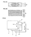
- Fig. 1(a) is a schematic sectional view illustrating the basic structure of a viewing angle control element according to the present invention
- Fig. 1(b) is a schematic sectional view illustrating a structural example of the viewing angle control element according to the present invention
- Fig. 2 is a structural diagram illustrating two-dimensionally the basic structure of the viewing angle control element according to the present invention.
- a viewing angle control element 10 according to this embodiment has a basic structure comprising a pair of polarizing layers 11, 13 and a liquid crystal layer 12 interposed between the polarizing layers. Further, as shown in Fig.
- transmission axes 11p, 13p of the polarizing layers 11, 13 are arranged to be parallel to each other, and the liquid crystal layer 12 includes liquid crystal twist-aligned by 180°.
- An aligned direction 12r1 of liquid crystal molecules adjacent to the polarizing layer 11 and the transmission axis 11p of the polarizing layer 11 are arranged to be parallel to each other, and an aligned direction 12r2 of liquid crystal molecules adjacent to the polarizing layer 13 and the transmission axis 13p of the polarizing layer 13 are parallel to each other.
- an aligned state of the liquid crystal layer 12 is electrically controllable, and can be shifted to another aligned state by applying an electric field to the liquid crystal layer 12 in the twist-aligned state.
- the viewing angle control element 10 can have a configuration, for example, shown in Fig. 1(b).
- the liquid crystal layer 12 is interposed between a pair of substrates 24, 25 arranged to face each other, and polarizers (polarizing layers) 21, 23 are arranged on the outer surface sides of the substrates 24, 25.
- An electrode layer 26 as voltage applying means to the liquid crystal layer 12 and an alignment film 27 as alignment regulating means for regulating an initial alignment of the liquid crystal layer 12 are sequentially formed on the inner surface side (on the liquid crystal layer 12 side) of the substrate 24, and an electrode layer 28 as voltage applying means and an alignment film 29 as alignment regulating means are sequentially formed on the inner surface side (on the liquid crystal layer 12 side) of the substrate 25.
- the electrode layers 26, 28 may be made of transparent conductive materials such as ITO.
- the alignment films 27, 29 may be made of organic materials such as polyimide or inorganic materials such as silicon oxide. When the alignment films 27, 29 are made of polyimide films, their rubbing directions and the transmission axes of the polarizers 21, 23 are arranged to be parallel to each other.
- the polarizers 21, 23 may be formed as polarizing layers on the inner surface side (on the liquid crystal layer 12 side) of the substrates 24, 25, and may be formed by using the polarizers 21, 23 as substrates.
- the liquid crystal layer 12 is regulated into a twist-aligned state by 180° by means of the alignment films 27, 29, and by changing the aligned state of the liquid crystal layer 12 with a voltage applied between the electrode layers 26, 28, the viewing angle characteristic of transmitted light can be controlled.
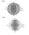
- the inventor verifies that the emission angle of the transmitted light can be controlled by means of the viewing angle control element 20 having the above configuration, and the verification result will be described with reference to Figs. 3 and 4.
- Figs. 3 and 4 are a diagram illustrating transmissivity distribution of the viewing angle control element 20, the transmissivity being measured while changing the measuring angle.
- the measuring method in a state where a planar light source is arranged on a back surface side (downside in the figure) of the viewing angle control element 20 shown in Fig. 1(b), a detector is arranged above the viewing angle control element 20, and the planar light source is turned on, the transmissivity of the viewing angle control element 20 was measured while changing the measuring angle of the detector (where a normal direction of the viewing angle control element 20 is supposed as 0°).
- Fig. 3 shows the measurement result in a state where a voltage is not applied to the electrode layers 26, 28 shown in Fig. 1(b)
- Fig. 4 shows the measurement result in a state where a voltage is applied to the electrode layers 26, 28 to align the liquid crystal molecules of the liquid crystal layer 12 to be substantially perpendicular to the substrates 24, 25.
- areas denoted by a reference numeral A are areas having a highest transmissivity
- areas denoting by reference numerals B, C and D are areas having a lower transmissivity in that order.
- a high transmissivity is obtained in all directions within a range of about 60° in an up-and-down direction and about 40° in a right-and-left direction from the front face of the viewing angle control element 20.
- the transmissivity distribution in the up-and-down direction from the front is almost equal to Fig. 3, but the transmissivity of a large angle side in the right-and-left direction from the front is lower than the state shown in Fig. 3.
- the viewing angle control element 20 according to this embodiment, it can be seen that, by switching the voltage applying condition to the electrode layers 26, 28, the emission angle of the transmitted light in the right-and-left direction can be narrowed without damaging the brightness in the up-and-down direction from the front of the viewing angle control element 20.
- the transmissivity distribution to the emission angle can be freely enlarged and lessened by means of adjustment of the voltage applying condition to the liquid crystal layer, the range of viewing angle in which information is visible can be freely changed by displaying various information transmitted through the viewing angle control element, so that an observer can enjoy an excellent display while effectively concealing data from a third party.
- the transmission axes 11p, 13p of the polarizing layers 11, 13 and the aligned directions 12r1, 12r2 of the liquid crystal molecules of the liquid crystal layer adjacent to the polarizing layers are parallel to each other, the axes or the aligned directions in manufacturing the viewing angle control element may be deviated from the parallel arrangement only if practical problems do not occur. That is, within a range where problems such as remarkably damaging the controllability of transmissivity within the range of emission angle at the front of the device do not occur, arrangement between the transmission axes and the liquid crystal molecules can be adjusted.
- FIG. 5 is a diagram illustrating a two-dimensional configuration of a viewing angle control element according to this embodiment.
- the basic structure of a viewing angle control element 30 according to this embodiment is similar to the viewing angle control element 10 according to the first embodiment shown in Fig. 1(a), where as shown in Fig.
- the transmission axis 11p of the polarizing layer 11 and the transmission axis 13p of the polarizing layer 13 are arranged to be parallel to each other, and the aligned direction 12r1 of the liquid crystal molecules of the liquid crystal layer 12 adjacent to the polarizing layer 11 and the aligned direction 12r2 of the liquid crystal molecules adjacent to the polarizing layer 13 are arranged to be perpendicular to each other.
- the configuration shown in Fig. 1(b) can be applied. That is, in the structural example shown in Fig. 1(b), by rotating the transmission axes of the polarizers 21, 23 by 90° from the arrangement of the first embodiment, the viewing angle control element having the basis structure shown in Fig. 5 can be obtained.
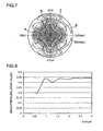
- Fig. 6 shows the measurement result in a state where a voltage is not applied to the liquid crystal layer
- Fig. 7 shows the measurement result in a state where a voltage is applied to the liquid crystal layer (in a state where the liquid crystal molecules are aligned to be perpendicular to the polarizing layers 11, 13).
- the area A with a high transmissivity occupies a wide range of angle similarly to the distribution shown in Fig. 3, and in a state where a voltage is applied to the liquid crystal layer shown in Fig. 7, the area A with a high transmissivity is narrowed remarkably compared with the distribution shown in Fig. 6. Therefore, it is possible to freely enlarge and lessen the range of viewing angle of the transmitted light by means of the viewing angle control element comprising the configuration according to this embodiment.
- Fig. 8 is a graph illustrating the measurement result, where an axis of abscissa expresses ⁇ nd ⁇ m and an axis of ordinate expresses brightness (transmissivity). As shown in Fig. 8, the brightness at the front side of the viewing angle control element 20 is gradually increased while repeating periodical up and down movement with respect to ⁇ nd.
- the inventor has verified a change of the aforementioned viewing angle restriction effect (an effect of narrowing the viewing angle by means of application of a voltage to the liquid crystal layer 12) by changing ⁇ nd of the liquid crystal layer 12.
- Fig. 9 is a graph illustrating a result of measuring the brightness (transmissivity) in the right-and-left direction from the front side of the viewing angle control element 20 in cases of eight kinds of liquid crystal layers 12 of which ⁇ nd is 1.0 ⁇ m to 8.0 ⁇ m, where the axis of abscissa expresses the measuring angle in the right-and-left direction from the front side of the viewing angle control element 20 and the axis of ordinate expresses the brightness (transmissivity). A voltage of 7V is applied to the liquid crystal layer 12 in measurement. As shown in Fig.
- the symmetry of the brightness (about 0°) tends to be damaged with increase of ⁇ nd, and the brightness is enhanced specifically in the vicinity of 20° to 30° in the positive viewing angle. Therefore, the range of ⁇ nd where a sufficient viewing angle can be secured in restricting the viewing angle is 8.0 ⁇ m or less, and the range of ⁇ nd where the symmetry of brightness can be also obtained is 5.0 ⁇ m or less.
- the asymmetry of brightness is generated because the amount of alignment change with respect to application of a voltage to the liquid crystal layer 12 is decreased with increase of ⁇ nd of the liquid crystal layer 12. Therefore, in a case where it is not necessary to consider power consumption of the viewing angle control element 20, by applying a higher voltage to the liquid crystal layer 12 to secure the symmetry of brightness, it is possible to obtain an excellent viewing angle restriction effect even when the liquid crystal having ⁇ nd of 5 ⁇ m or more is used.
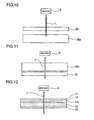
- FIGs. 10 and 11 are schematic structural diagrams illustrating a display device comprising the viewing angle control element 20 according the aforementioned embodiment, where Fig. 10 shows an example where the viewing angle control element 20 is provided at the front surface side (an observer O side) of the display element 35a, and Fig. 11 shows an example where the viewing angle control element 20 is provided at the back surface side (a side opposite to an observer O) of the display element 35b.
- a display is carried out on the observer O by allowing the display light L of the display element 35a to be transmitted through the viewing angle control element 20. Then, by electrically controlling the liquid crystal layer 12 of the viewing angle control element 20 according to the aforementioned embodiment, the emission angle (that is, viewing angle) of the display light L can be freely increased and decreased. Therefore, according to the display device of this embodiment, in a state where the viewing angle of the display light L is narrowed by means of the viewing angle control element 20, the concealment of displayed information from a third party can be very easily performed, and in the situation requiring the concealment of information, an excellent visibility is obtained by not allowing the viewing angle control to be performed by means of the viewing angle control element 20.
- a light-emission type display element such as a cathode ray tube (CRT) display element, an electroluminescent (EL) display element, or a plasma display panel (PDP), or a light shutter type display element such as a liquid crystal display element.
- CTR cathode ray tube
- EL electroluminescent
- PDP plasma display panel
- a light shutter type display element such as a liquid crystal display element.
- the viewing angle control element 20 is provided on the front surface of the display element 35a, it is specifically effective that the light-emission type display element or the liquid crystal display element with a wide viewing angle is used as the display element 35a.
- the display device shown in Fig. 11 by allowing the light supplied from a light source, etc. to be incident on the display element 35b after the viewing angle is controlled by means of the viewing angle control element 20 in advance, the display is carried out on the observer O.
- the light-shutter type display element such as a liquid crystal display element is used as the display element 35b.
- the display element 35b is arranged at the first front surface as seen from the observer O, so that it is possible to obtain a clear display without parallax.
- a display device shown in Fig. 12 has a structure obtained by sequentially laminating a polarizing layer 11, a liquid crystal layer 12, a polarizing layer 13a, a liquid crystal layer 36 and a polarizing layer 38 from the upside of the figure. That is, the polarizing layers 11, 13a and the liquid crystal layer 12 interposed therebetween at the upside of the figure constitute a viewing angle control element having the same function as the viewing angle control element 10 according to the first embodiment, and the polarizing layers 13a, 38 and the liquid crystal layer 36 interposed therebetween at the downside of the figure constitute a liquid crystal display element.
- the viewing angle control element and the liquid crystal display element share the polarizing layer 13a.
- the liquid crystal display element is schematically described as comprising only the liquid crystal layer 36 and the polarizing layers 38, 13a for interposing the liquid crystal layer therebetween, but actually, it is needless to say that the liquid crystal display element further comprises alignment films or electrodes for driving and controlling alignment of the liquid crystal, phase difference layers, etc.
- the display device having the aforementioned configuration modulates the light L of a light source, etc. incident from the downside of the figure (from the outer surface side of the polarizing layer 38) by means of the liquid crystal layer 36 to generate the display light forming an image, and then controls the emission angle (viewing angle) of the display light incident on the liquid crystal layer 12. Accordingly, compared with a case where a display device is constructed by laminating the viewing angle control element and the liquid crystal display element individually prepared, it is possible to realize decrease of the thickness of the display device and reduction of the number of components, and it is also possible to suppress attenuation of the display light due to transmission through the polarizing layer, so that it is possible to provide a bright and thin display device at low cost.
- the display device shown in Fig. 13 has a structure where a polarizing layer 39, a liquid crystal layer 36, a polarizing layer 11a, a liquid crystal layer 12 and a polarizing layer 13 are sequentially laminated from the upside of the figure. That is, the polarizing layers 11a, 13 at the downside of the figure and the liquid crystal layer 12 interposed therebetween constitute a viewing angle control element having the same function as the viewing angle control element 10 according to the aforementioned first embodiment, and the polarizing layers 39 at the upside of the figure, the polarizing layer 11a and the liquid crystal layer 36 interposed therebetween constitute a liquid crystal display element. Therefore, the liquid crystal display element and the viewing angle control element share the polarizing layer 11a.
- the liquid crystal display element is schematically described as comprising only the liquid crystal layer 36 and the polarizing layers 11a, 39 for interposing the liquid crystal layer therebetween, but actually, it is needless to say that the liquid crystal display element further comprises alignment films or electrodes for driving and controlling the alignment of the liquid crystal, phase difference plates, etc.
- the display device having the above configuration first controls the emission angle (viewing angle) by means of the liquid crystal layer 12, then allows the light L of a light source, etc. incident from the downside of the figure (from the outer surface side of the polarizing layer 13) to be incident on the liquid crystal layer 36, modulates the light by means of the liquid crystal layer 36 to generate the display light, and then performs the display to an observer O.
- a display device is constructed by laminating the viewing angle control element and the liquid crystal display element individually prepared, it is possible to realize decrease of the thickness of the display device and reduction of the number of components, and it is also possible to suppress attenuation of the display light due to transmission through the polarizing layer, so that it is possible to provide a bright and thin display device at low cost.
- the display device comprises an EL display element as the display element 37, and has a structure where a viewing angle control element obtained by laminating a circularly polarizing layer 13b, the liquid crystal layer 12 and the polarizing layer 11 is provided on the EL display element 37.
- the viewing angle control element provided on the EL display element 37 has the same function as the viewing angle control element 10 according to the first embodiment, except that the circularly polarizing layer 13b is provided on one side surface of the viewing angle control element.
- the circularly polarizing layer 13b interposed between the EL display element 37 and the liquid crystal layer 12 functions to remove a specular effect of the EL display element, and thus the visibility of the display device can be improved.
- the circularly polarizing layer 13b for example, an optical film obtained by laminating a phase difference layer and a polarizing layer can be used.
- the phase difference layer is provided on the EL display element 37 side
- the polarizing layer is provided on the liquid crystal layer 12 side.
- the viewing angle control element 10 comprising the polarizing layers 11, 13 and the liquid crystal layer 12 interposed therebetween, and a liquid crystal display element 35 comprising polarizing layers 38, 39 and a liquid crystal layer 36 interposed therebetween are laminated with an optical rotation element (optical rotation means) 40 therebetween.
- the viewing angle is controlled by means of the viewing angle control element 10, and then the light L of a light source, etc. incident on the viewing angle control element 10 is allowed to be incident on the optical rotation element 40.
- a direction of the transmission axis of the polarizing layer of the viewing angle control element 10 can be set to any direction without depending upon the direction of the transmission axis of the liquid crystal display element 35. Therefore, even if the arrangement of the polarizing layers 38, 39 of the liquid crystal display element 35 is set to the direction where a high contrast display is obtained, the directions of the polarizing layers 11, 13 of the viewing angle control element 10 for controlling the viewing angle can be set to a direction in which the viewing angle is properly controlled, so that it is possible to allow the high quality display to be compatible with the excellent viewing angle control function.
- the viewing angle control element 10 is arranged at the back surface side of the liquid crystal display element 35 as seen from the observer O
- the positional relation of the viewing angle control element 10 and the liquid crystal display element 35 may be inverted.
- the liquid crystal display element 35 is arranged at the observer O side, but since the viewing angle control by the viewing angle control element 10 is carried out prior to the optical modulation by the liquid crystal display element 35, the display at a high angle side becomes a little dark. Therefore, it is preferable that arrangement of the liquid crystal display element 35 and the viewing angle control element 10 is determined in consideration of brightness and clearness of the display. Now, differences in viewing angle characteristics based on the arrangement will be described with reference to the drawings.
- Fig. 16 and 17 are diagrams illustrating transmissivity distribution of the display device according to this embodiment, where the transmissivity has been measured while changing the measurement angle.
- the measuring method is similar to the first embodiment.
- Fig. 16 shows a measurement result in a state where a voltage is not applied to the liquid crystal layer 12
- Fig. 17 shows a measurement result in a state where a voltage is applied to the liquid crystal layer 12.
- switching of the display to a wide viewing angle or a narrow viewing angle can be also easily carried out by switching the voltage applying condition to the liquid crystal layer 12.
- the viewing angle control element 10 is arranged at a front surface side (the observer O side) of the liquid crystal display element 35, the viewing angle characteristic as shown in Figs. 3 and 4 is obtained. Therefore, if comparing Fig. 16 with Fig. 3, in a state where a voltage is not applied, a bright display is obtained with a wider range of viewing angle by arranging the viewing angle control element 10 at the front surface side of the liquid crystal display element 35. However, by arranging the viewing angle control element 10 at the front surface side, the clearness of the display is deteriorated.
- phase difference film having an in-plane phase difference or a half-wave plate comprising a laminated structure of the phase difference film may be used.
- the optical rotation element 40 may comprise liquid crystal having a twist structure of the element in its thickness direction.
- the twist angle of the twist structure is an angle which the optical axis direction of the polarizing layer 11 of the viewing angle control element 10 and the optical axis direction of the polarizing layer 38 of the liquid crystal display element 35 form, and ⁇ nd ( ⁇ m) of the liquid crystal is larger than 1/200 of an angle which the optical axes of the polarizing layers 11, 38 form.
- a viewing angle control element according to this embodiment of which the sectional structure is shown in Fig. 19 comprises polarizing layers 11, 13 and phase difference layers 14, 15 and the liquid crystal layer 12 interposed therebetween, and can be arranged, for example, at the front surface side of the liquid crystal display element 20, similarly to the aforementioned embodiment.
- the liquid crystal layer 12 includes a liquid crystal twist-aligned by 180°, and the transmission axes of the polarizing layers 11, 13 are parallel to each other.
- the viewing angle control element 50 has a configuration similar to the viewing angle control element according to the first embodiment, except that the phase difference layers 14, 15 are provided.
- phase difference films phase difference films having an optical axis in its thickness direction, that is, so-called C plates
- C plates phase difference films which have retardation not in its in-plane direction but only in its thickness direction, and of which a refractive index in the thickness direction is smaller than a refractive index in the in-plane direction
- the retardation of the phase difference film in its thickness direction is d ⁇ ((nx+ny)/2-nz), where d is thickness.
- phase difference film By using such phase difference film, the alignment of the optical axes with the polarizing layers 11, 13 is not necessary, so that it is possible to improve facility of manufacture.
- phase difference layers 14, 15 are arranged on both sides of the liquid crystal layer 12, but the arrangement is not limited thereto. That is, a single phase-difference layer 14 may be provided between the liquid crystal layer 12 and the polarizing layer 11, and the two phase-difference layers 14, 15 are superposed and arranged between the liquid crystal layer 12 and the polarizing layer 11.
- a single phase-difference layer 14 may be provided between the liquid crystal layer 12 and the polarizing layer 11
- the two phase-difference layers 14, 15 are superposed and arranged between the liquid crystal layer 12 and the polarizing layer 11.
- the viewing angle control element 50 according to this embodiment having the aforementioned configuration, by providing the phase difference layers 14, 15, it is specifically possible to narrow the range of viewing angle in restricting the viewing angle.
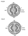
- Fig. 20 is a diagram illustrating the transmissivity distribution in a state where the viewing angle control element 50 according to this embodiment is arranged at the front surface side of the liquid crystal display element 20
- Fig. 21 is a diagram illustrating the transmissivity distribution in a case where ⁇ nd of the liquid crystal layer of the viewing angle control element 10 according to the first embodiment is set to 2.0 for the purpose of comparison.
- the white area denoted by a reference numeral E in Figs. 20 and 21 is an area where the transmissivity (brightness) is 10% or less of the transmissivity in the front direction (the center of the distribution diagram), and thus in this area E, the display of the liquid crystal display element 20 at the back side is dark enough almost not to be recognizable.
- the method of measuring the transmissivity distributions shown in Figs. 20 and 21 is similar to the first embodiment, and the phase difference layers 14, 15 used for the measurement are C plates having a phase difference of 200 nm in its thickness direction.
- the display device comprising the viewing angle control element 50 (Fig. 20) having the phase difference layers 14, 15 at the inside of the polarizing layers 11, 12 has the area E wider than the display device comprising the viewing angle control element 10 according to the above embodiment, so that it is possible to conceal the display with a wider range of viewing angle and have excellent viewing angle controllability.
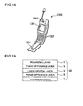
- FIG. 18 is a perspective view illustrating an example of an electronic apparatus according to the present invention.
- a mobile phone 1300 shown in the figure has the display device according to the present invention as a small-sized display unit 1301, and comprises a plurality of manipulation buttons 1302, an earpiece 1303 and a mouthpiece 1304.
- the display devices according to the aforementioned embodiments are not limited to the mobile phone, but can be suitably used as image display means of an electronic book, a personal computer, a digital still camera, a liquid crystal television, a view finder type or monitor direct vision-type video tape recorder, a car navigation apparatus, a pager, an electronic note, an electronic calculator, a word processor, a work station, a television phone, a POS terminal, an apparatus including a touch panel and the like.
- the display devices can very easily perform the switching between the wide viewing angle and the narrow viewing angle in any electronic apparatus, has an excellent concealment property of information, and enables a display with a high quality.
Landscapes
- Physics & Mathematics (AREA)
- Nonlinear Science (AREA)
- Optics & Photonics (AREA)
- General Physics & Mathematics (AREA)
- Crystallography & Structural Chemistry (AREA)
- Chemical & Material Sciences (AREA)
- Health & Medical Sciences (AREA)
- Mathematical Physics (AREA)
- Life Sciences & Earth Sciences (AREA)
- Hematology (AREA)
- Engineering & Computer Science (AREA)
- Veterinary Medicine (AREA)
- Public Health (AREA)
- Anesthesiology (AREA)
- General Health & Medical Sciences (AREA)
- Animal Behavior & Ethology (AREA)
- Heart & Thoracic Surgery (AREA)
- Biomedical Technology (AREA)
- Liquid Crystal (AREA)
- Pulmonology (AREA)
- Biophysics (AREA)
- Vascular Medicine (AREA)
- Polarising Elements (AREA)
- Electroluminescent Light Sources (AREA)
Claims (19)
- Vorrichtung zur Ansteuerung des Blickwinkelbereichs (10), umfassend
ein Paar von polarisierenden Schichten (11, 13) mit Transmissionsachsen (11p, 13p), die so angeordnet sind, dass sie im Wesentlichen parallel zueinander liegen; und
eine Flüssigkristallschicht (12), die zwischen dem Paar von polarisierenden Schichten (11, 13) angeordnet ist und elektrisch ansteuerbar ist, und
ein Mittel zur Induzierung einer Ausrichtung der Flüssigkristallmoleküle, dadurch gekennzeichnet, dass
die Flüssigkristallmoleküle neben der einen polarisierenden Schicht (11) und Flüssigkristallmoleküle neben der anderen polarisierenden Schicht (13) so ausgerichtet sind, dass sie im Wesentlichen parallel zu den Transmissionsachsen (11p, 13p) der polarisierenden Schichten (11, 13) liegen, oder Flüssigkristallmoleküle neben der einen polarisierenden Schicht (11) und Flüssigkristallmoleküle neben der anderen polarisierenden Schicht (13) so ausgerichtet sind, dass sie im Wesentlichen senkrecht zu den Transmissionsachsen (11p, 13p) der polarisierenden Schichten (11, 13) liegen. - Vorrichtung zur Ansteuerung des Blickwinkelbereichs (10) nach Anspruch 1,
wobei die Flüssigkristallschicht (12) Flüssigkristall enthält, der um etwa 180° verdreht ausgerichtet ist, und
wobei Flüssigkristallmoleküle neben den polarisierenden Schichten (11, 13) so ausgerichtet sind, dass sie im Wesentlichen parallel zu den Transmissionsachsen (11p, 13p) der polarisierenden Schichten (11, 13) liegen. - Vorrichtung zur Ansteuerung des Blickwinkelbereichs (10) nach Anspruch 1,
wobei Flüssigkristallmoleküle neben der einen polarisierenden Schicht (11) und Flüssigkristallmoleküle neben der anderen polarisierenden Schicht (13) so ausgerichtet sind, dass sie im Wesentlichen parallel zu den Transmissionsachsen (11p, 13p) der am nächsten liegenden polarisierenden Schicht liegen. - Vorrichtung zur Ansteuerung des Blickwinkelbereichs (10) nach Anspruch 1,
wobei Flüssigkristallmoleküle neben der einen polarisierenden Schicht (11) und Flüssigkristallmoleküle neben der anderen polarisierenden Schicht (13) so ausgerichtet sind, dass sie im Wesentlichen senkrecht zu den Transmissionsachsen (11p, 13p) der am nächsten liegenden polarisierenden Schicht (11, 13) liegen. - Vorrichtung zur Ansteuerung des Blickwinkelbereichs (10) nach einem der Ansprüche 1 bis 4,
wobei das Produkt Δnd der Brechungsindexanisotropie Δn der Flüssigkristallschicht (12) und der Dicke d der Flüssigkristallschicht (12) gleich oder größer 1,0 µm ist. - Vorrichtung zur Ansteuerung des Blickwinkelbereichs (10) nach einem der Ansprüche 1 bis 4,
wobei das Produkt Δnd der Brechungsindexanisotropie Δn der Flüssigkristallschicht (12) und der Dicke d der Flüssigkristallschicht (12) gleich oder kleiner 8,0 µm ist. - Vorrichtung zur Ansteuerung des Blickwinkelbereichs (10) nach einem der Ansprüche 1 bis 4,
wobei das Produkt Δnd der Brechungsindexanisotropie An der Flüssigkristallschicht (12) und der Dicke d der Flüssigkristallschicht (12) gleich oder größer 2,0 µm ist und gleich oder kleiner 5,0 µm ist. - Vorrichtung zur Ansteuerung des Blickwinkelbereichs (10) nach einem der Ansprüche 1 bis 7,
wobei eine Phasendifferenzschicht (14, 15) zwischen dem Paar von polarisierenden Schichten (11, 13) bereitgestellt ist. - Vorrichtung zur Ansteuerung des Blickwinkelbereichs (10) nach Anspruch 8,
wobei die Phasendifferenzschicht (14, 15) an beiden Seiten der Flüssigkristallschicht (12) bereitgestellt ist. - Vorrichtung zur Ansteuerung des Blickwinkelbereichs (10) nach Anspruch 8 oder 9,
wobei die Phasendifferenzschicht (14, 15) eine vorbestimmte optische Verzögerung in ihre Dickenrichtung hat. - Anzeigevorrichtung, umfassend die Vorrichtung zur Ansteuerung des Blickwinkelbereichs (10) nach einem der Ansprüche 1 bis 10 und ein Anzeigeelement (35),
wobei der Blickwinkelbereich des Anzeigeelements (35) mit Hilfe der Vorrichtung zur Ansteuerung des Blickwinkelbereichs (10) eingestellt werden kann. - Anzeigevorrichtung nach Anspruch 11,
wobei das Anzeigeelement (35) ein Flüssigkristallanzeigeelement umfasst, und die Vorrichtung zur Ansteuerung des Blickwinkelbereichs (10) an der Vorderseite oder der Rückseite des Flüssigkristallanzeigeelements (35) bereitgestellt ist. - Anzeigevorrichtung nach Anspruch 12,
wobei die polarisierende Schicht (11a) der Vorrichtung zur Ansteuerung des Blickwinkelbereichs (10) an der Seite des Flüssigkristallanzeigeelements als polarisierende Schicht (11a) des Flüssigkristallanzeigeelements (35) dient. - Anzeigevorrichtung nach Anspruch 12,
wobei ein optisches Rotationsmittel (40) zur Einstellung einer Abweichung zwischen einer Transmissionsachse einer polarisierenden Schicht (38), die auf einer Oberfläche des Flüssigkristallanzeigeelements (35) bereitgestellt ist, die der Vorrichtung zur Ansteuerung des Blickwinkelbereichs zugewandt ist, und den Transmissionsachsen (11p, 13p) der polarisierenden Schichten (11, 13) der Vorrichtung zur Ansteuerung des Blickwinkelbereichs (10) zwischen dem Flüssigkristallanzeigeelement und der Vorrichtung zur Ansteuerung des Blickwinkelbereichs (10) bereitgestellt ist. - Anzeigevorrichtung nach Anspruch 14,
wobei das optische Rotationsmittel (40) ein Halbwellenlängenplättchen ist. - Anzeigevorrichtung nach Anspruch 14,
wobei das optische Rotationsmittel (40) einen verdreht ausgerichteten Flüssigkristall hat. - Anzeigevorrichtung nach Anspruch 11,
wobei das Anzeigeelement (35) ein EL-Anzeigeelement umfasst, eine kreisförmig polarisierende Schicht zwischen dem EL-Anzeigeelement und der Vorrichtung zur Ansteuerung des Blickwinkelbereichs (10) bereitgestellt ist, und die polarisierende Schicht (11, 13) der Vorrichtung zur Ansteuerung des Blickwinkelbereichs (10) an der Seite des EL-Anzeigeelements einen Teil der kreisförmig polarisierenden Schicht bildet. - Elektronisches Gerät, umfassend die Vorrichtung zur Ansteuerung des Blickwinkelbereichs (10) nach einem der Ansprüche 1 bis 10.
- Elektronisches Gerät, umfassend die Anzeigevorrichtung nach einem der Ansprüche 11 bis 17.
Applications Claiming Priority (4)
| Application Number | Priority Date | Filing Date | Title |
|---|---|---|---|
| JP2003131672 | 2003-05-09 | ||
| JP2003131672 | 2003-05-09 | ||
| JP2004025421 | 2004-02-02 | ||
| JP2004025421A JP3823972B2 (ja) | 2003-05-09 | 2004-02-02 | 視角制御素子、表示装置、及び電子機器 |
Publications (2)
| Publication Number | Publication Date |
|---|---|
| EP1475655A1 EP1475655A1 (de) | 2004-11-10 |
| EP1475655B1 true EP1475655B1 (de) | 2006-09-13 |
Family
ID=32993123
Family Applications (1)
| Application Number | Title | Priority Date | Filing Date |
|---|---|---|---|
| EP04252464A Expired - Lifetime EP1475655B1 (de) | 2003-05-09 | 2004-04-28 | Vorrichtung zur Ansteuerung des Blickwinkelbereichs, Anzeigevorrichtung und elektronisches Gerät |
Country Status (7)
| Country | Link |
|---|---|
| US (1) | US7400367B2 (de) |
| EP (1) | EP1475655B1 (de) |
| JP (1) | JP3823972B2 (de) |
| KR (1) | KR100685569B1 (de) |
| CN (1) | CN1332256C (de) |
| DE (1) | DE602004002315T2 (de) |
| TW (1) | TW200508697A (de) |
Cited By (1)
| Publication number | Priority date | Publication date | Assignee | Title |
|---|---|---|---|---|
| WO2013049088A1 (en) * | 2011-09-30 | 2013-04-04 | 3M Innovative Properties Company | Electronically switchable privacy film and display device having same |
Families Citing this family (43)
| Publication number | Priority date | Publication date | Assignee | Title |
|---|---|---|---|---|
| US7683875B2 (en) * | 2003-03-31 | 2010-03-23 | Sharp Kabushiki Kaisha | Liquid crystal display device and electronic device |
| GB2413394A (en) | 2004-04-20 | 2005-10-26 | Sharp Kk | Display |
| JP4668549B2 (ja) * | 2004-04-21 | 2011-04-13 | 大日本印刷株式会社 | 位相差量可変な光学補償素子およびそれを用いた液晶ディスプレイ |
| US20060044290A1 (en) * | 2004-08-24 | 2006-03-02 | Hurwitz Roger A | Electronic privacy filter |
| JPWO2006025340A1 (ja) * | 2004-08-30 | 2008-05-08 | シャープ株式会社 | 表示制御デバイス、表示装置、表示デバイスの制御方法、表示制御プログラム、および該プログラムを記録した記録媒体 |
| JPWO2006025326A1 (ja) * | 2004-08-31 | 2008-05-08 | シャープ株式会社 | 視野角制御デバイス、表示装置、視野角制御デバイスの制御方法、視野角制御プログラム、および該プログラムを記録した記録媒体 |
| KR100809231B1 (ko) * | 2004-09-07 | 2008-03-05 | 샤프 가부시키가이샤 | 표시 장치, 시야각 제어 장치, 및 전자 기기 |
| US7817106B2 (en) * | 2004-09-15 | 2010-10-19 | Sharp Kabushiki Kaisha | Display device, viewing angle control device, and electronic apparatus |
| US8031273B2 (en) * | 2004-09-17 | 2011-10-04 | Sharp Kabushiki Kaisha | Display device, viewing angle control device, and electronic device |
| WO2006038574A1 (ja) * | 2004-10-04 | 2006-04-13 | Sharp Kabushiki Kaisha | 表示装置および電子機器 |
| US20070297064A1 (en) * | 2004-10-27 | 2007-12-27 | Fujitsu Ten Limited | Display Device |
| JP4536489B2 (ja) | 2004-11-15 | 2010-09-01 | 株式会社 日立ディスプレイズ | 光学素子及びそれを用いた表示装置 |
| EP1865364A4 (de) * | 2005-04-01 | 2012-03-28 | Sharp Kk | Mobiles informationsendgerät und display-endgerät |
| JP2006330164A (ja) * | 2005-05-24 | 2006-12-07 | Casio Comput Co Ltd | 液晶表示装置 |
| US7965268B2 (en) * | 2005-07-08 | 2011-06-21 | Sharp Kabushiki Kaisha | Display device and liquid crystal display panel |
| KR101258591B1 (ko) * | 2005-12-23 | 2013-05-02 | 엘지디스플레이 주식회사 | 액정표시장치 및 그 구동방법 |
| KR100816078B1 (ko) * | 2006-06-19 | 2008-03-24 | 광운대학교 산학협력단 | 공간영상 투영장치 및 그 방법 |
| KR100998385B1 (ko) * | 2006-07-05 | 2010-12-03 | 샤프 가부시키가이샤 | 액정 표시 장치 및 시야각 제어 패널 |
| US8045097B2 (en) * | 2006-08-09 | 2011-10-25 | Sharp Kabushiki Kaisha | Liquid crystal display device and viewing angle control module |
| JP5043019B2 (ja) * | 2006-09-07 | 2012-10-10 | シャープ株式会社 | 液晶表示装置 |
| JP4572888B2 (ja) | 2006-10-30 | 2010-11-04 | ソニー株式会社 | 液晶装置及び電子機器 |
| GB2443648A (en) * | 2006-11-07 | 2008-05-14 | Sharp Kk | LC display having public and private viewing modes arranged to display a first image in the public mode and second and third spatially interlaced images in th |
| JP2008139769A (ja) * | 2006-12-05 | 2008-06-19 | Tohoku Univ | 視野角制御液晶パネル |
| KR101476841B1 (ko) | 2006-12-28 | 2014-12-24 | 엘지디스플레이 주식회사 | 시야각 제어 액정표시장치 |
| US8698988B2 (en) | 2007-01-09 | 2014-04-15 | Japan Display West Inc. | Liquid crystal device having viewing angle control pixels |
| JP2008275966A (ja) * | 2007-05-01 | 2008-11-13 | Epson Imaging Devices Corp | 液晶表示装置および電子機器 |
| WO2008143256A1 (ja) * | 2007-05-21 | 2008-11-27 | Sharp Kabushiki Kaisha | ディスプレイおよびそれに用いられる視野角制御素子 |
| CN101681061B (zh) * | 2007-07-09 | 2012-01-11 | 夏普株式会社 | 视野角控制元件和具备其的显示装置 |
| KR100869810B1 (ko) * | 2007-08-02 | 2008-11-21 | 삼성에스디아이 주식회사 | 표시 장치 |
| EP2199848A4 (de) * | 2007-10-18 | 2011-07-20 | Sharp Kk | Flüssigkristallanzeigeeinrichtung |
| CN101458411B (zh) * | 2007-12-12 | 2012-08-29 | 奇美电子股份有限公司 | 视角可调的液晶显示装置 |
| US8681294B2 (en) * | 2008-12-02 | 2014-03-25 | Hiap L. Ong & Kyoritsu Optronics Co., Ltd. | Optical compensation film for LCD viewing angles reduction |
| EP2685307B1 (de) * | 2011-03-11 | 2019-07-10 | Citizen Watch Co., Ltd. | Lichtmodulationselement und mit dem lichtmodulationselement ausgestattete mikroskopvorrichtung |
| KR20130048070A (ko) * | 2011-11-01 | 2013-05-09 | 삼성디스플레이 주식회사 | 표시장치 |
| JP6359338B2 (ja) * | 2014-05-22 | 2018-07-18 | スタンレー電気株式会社 | 液晶表示装置 |
| CN106353941A (zh) * | 2016-10-31 | 2017-01-25 | 亚世光电股份有限公司 | 一种可直接反向视角的tft液晶模组 |
| JP2020529627A (ja) | 2018-01-04 | 2020-10-08 | エルジー・ケム・リミテッド | 液晶表示装置およびその製造方法 |
| CN110361883B (zh) | 2018-03-26 | 2023-04-28 | 中强光电股份有限公司 | 防窥控制装置与采用其的背光模块与显示器 |
| CN208126055U (zh) | 2018-04-28 | 2018-11-20 | 扬升照明股份有限公司 | 显示装置 |
| US10739625B2 (en) * | 2018-08-29 | 2020-08-11 | Innolux Corporation | Display device |
| JP7312632B2 (ja) * | 2019-07-17 | 2023-07-21 | 株式会社ジャパンディスプレイ | 光学素子および液晶表示装置 |
| JP7395328B2 (ja) * | 2019-11-14 | 2023-12-11 | 株式会社ジャパンディスプレイ | 車両用表示装置 |
| JP2021156943A (ja) * | 2020-03-25 | 2021-10-07 | 株式会社ジャパンディスプレイ | 表示装置、車両用表示装置、及び、車両 |
Family Cites Families (34)
| Publication number | Priority date | Publication date | Assignee | Title |
|---|---|---|---|---|
| US4927240A (en) * | 1983-11-02 | 1990-05-22 | Michael Stolov | Multiple liquid crystal display |
| JPS6146930A (ja) | 1984-08-10 | 1986-03-07 | Ricoh Co Ltd | 液晶表示方法および表示装置 |
| JPH0656459B2 (ja) | 1985-04-05 | 1994-07-27 | 株式会社日立製作所 | 液晶表示素子 |
| JPS62143990A (ja) * | 1985-12-18 | 1987-06-27 | Hitachi Ltd | 液晶表示素子 |
| KR900008302B1 (ko) | 1987-12-30 | 1990-11-12 | 삼성전자 주식회사 | 디지탈 적산 전력계의 역률 측정회로 및 방법 |
| JP2523811B2 (ja) * | 1988-09-02 | 1996-08-14 | 株式会社日立製作所 | 液晶光変調装置 |
| EP0367616A3 (de) * | 1988-11-04 | 1991-04-24 | Matsushita Electric Industrial Co., Ltd. | Optisches Flüssigkristall-Element |
| JP2721284B2 (ja) | 1991-02-07 | 1998-03-04 | 株式会社東芝 | 液晶表示素子および光学異方素子 |
| EP0528542B1 (de) * | 1991-07-19 | 1998-09-16 | SHARP Corporation | Optisches Modulationselement und Vorrichtungen mit einem solchen Element |
| JP3087861B2 (ja) | 1991-10-14 | 2000-09-11 | 日本電信電話株式会社 | 視野角制御型表示装置 |
| US5572343A (en) * | 1992-05-26 | 1996-11-05 | Olympus Optical Co., Ltd. | Visual display having see-through function and stacked liquid crystal shutters of opposite viewing angle directions |
| JP3006643B2 (ja) * | 1992-10-05 | 2000-02-07 | 富士通株式会社 | 液晶表示装置 |
| JPH07244284A (ja) * | 1994-03-02 | 1995-09-19 | Fujitsu Ltd | 液晶表示装置 |
| US5680184A (en) * | 1994-04-12 | 1997-10-21 | Casio Computer Co., Ltd. | Color liquid crystal display device |
| US5751385A (en) * | 1994-06-07 | 1998-05-12 | Honeywell, Inc. | Subtractive color LCD utilizing circular notch polarizers and including a triband or broadband filter tuned light source or dichroic sheet color polarizers |
| JPH07333640A (ja) * | 1994-06-14 | 1995-12-22 | Toshiba Corp | 液晶表示素子 |
| JP3184069B2 (ja) * | 1994-09-02 | 2001-07-09 | シャープ株式会社 | 画像表示装置 |
| JPH0943654A (ja) * | 1995-07-31 | 1997-02-14 | Hitoshi Nitta | 並列光論理演算素子及び装置 |
| TW332870B (en) * | 1995-08-17 | 1998-06-01 | Toshiba Co Ltd | LCD and optical anisotropy device |
| JP3481741B2 (ja) * | 1995-09-06 | 2003-12-22 | セイコーエプソン株式会社 | 画像表示装置 |
| DE69634849T2 (de) * | 1995-09-25 | 2006-05-18 | Koninklijke Philips Electronics N.V. | Elektrolumineszentes beleuchtungssystem und flachtafelbildanzeigevorrichtung mit einem solchen system |
| KR100218983B1 (ko) | 1995-10-24 | 1999-09-01 | 손욱 | 어카이랄스멕틱 시 액정 물질을 이용한 액정 표시 장치 |
| KR100241816B1 (ko) | 1995-11-24 | 2000-02-01 | 니시무로 타이죠 | 액정표시소자 및 광학이방소자 |
| GB9608175D0 (en) * | 1996-04-19 | 1996-06-26 | Ncr Int Inc | Method of controlling veiwability of a display screen and a device therefor |
| JP3833777B2 (ja) * | 1997-04-25 | 2006-10-18 | 旭硝子株式会社 | カラー液晶表示装置 |
| JP3322197B2 (ja) * | 1997-12-17 | 2002-09-09 | 松下電器産業株式会社 | 液晶表示装置 |
| JP2000047195A (ja) | 1998-07-30 | 2000-02-18 | Casio Comput Co Ltd | 液晶表示装置 |
| US6642984B1 (en) * | 1998-12-08 | 2003-11-04 | Fujitsu Display Technologies Corporation | Liquid crystal display apparatus having wide transparent electrode and stripe electrodes |
| KR20000066806A (ko) * | 1999-04-21 | 2000-11-15 | 구본준 | 광시야각과 협시야각 모드전환이 가능한 액정표시장치 |
| KR100695297B1 (ko) | 2000-06-13 | 2007-03-14 | 삼성전자주식회사 | 보상 필름을 이용한 광시야각 액정 표시 장치 |
| US6490076B2 (en) * | 2001-01-11 | 2002-12-03 | Hrl Laboratories, Llc | Optical phased array for depolarized optical beam control |
| JP2002297044A (ja) | 2001-03-29 | 2002-10-09 | Toshiba Corp | 狭視野角モバイルディスプレイ、それに用いるフィルターの製造方法、および携帯端末装置 |
| JP4425496B2 (ja) | 2001-07-03 | 2010-03-03 | アルパイン株式会社 | 表示装置 |
| JP2004062094A (ja) | 2002-07-31 | 2004-02-26 | Sony Ericsson Mobilecommunications Japan Inc | 携帯端末装置及び視野角可変表示装置 |
-
2004
- 2004-02-02 JP JP2004025421A patent/JP3823972B2/ja not_active Expired - Lifetime
- 2004-04-27 US US10/832,275 patent/US7400367B2/en active Active
- 2004-04-28 DE DE602004002315T patent/DE602004002315T2/de not_active Expired - Lifetime
- 2004-04-28 EP EP04252464A patent/EP1475655B1/de not_active Expired - Lifetime
- 2004-05-05 TW TW093112678A patent/TW200508697A/zh unknown
- 2004-05-07 KR KR1020040032356A patent/KR100685569B1/ko active IP Right Grant
- 2004-05-09 CN CNB2004100347333A patent/CN1332256C/zh not_active Expired - Lifetime
Cited By (1)
| Publication number | Priority date | Publication date | Assignee | Title |
|---|---|---|---|---|
| WO2013049088A1 (en) * | 2011-09-30 | 2013-04-04 | 3M Innovative Properties Company | Electronically switchable privacy film and display device having same |
Also Published As
| Publication number | Publication date |
|---|---|
| DE602004002315T2 (de) | 2007-09-20 |
| JP2004361917A (ja) | 2004-12-24 |
| US7400367B2 (en) | 2008-07-15 |
| CN1550840A (zh) | 2004-12-01 |
| EP1475655A1 (de) | 2004-11-10 |
| KR100685569B1 (ko) | 2007-02-22 |
| TWI326367B (de) | 2010-06-21 |
| US20040252258A1 (en) | 2004-12-16 |
| TW200508697A (en) | 2005-03-01 |
| KR20040095736A (ko) | 2004-11-15 |
| JP3823972B2 (ja) | 2006-09-20 |
| DE602004002315D1 (de) | 2006-10-26 |
| CN1332256C (zh) | 2007-08-15 |
Similar Documents
| Publication | Publication Date | Title |
|---|---|---|
| EP1475655B1 (de) | Vorrichtung zur Ansteuerung des Blickwinkelbereichs, Anzeigevorrichtung und elektronisches Gerät | |
| JP4819122B2 (ja) | 液晶表示装置及び視野角制御パネル | |
| US7468770B2 (en) | Viewing angle control element, method of manufacturing the same, liquid crystal display device, and electronic apparatus | |
| JP5131510B2 (ja) | 液晶表示装置、及び端末装置 | |
| JP4005808B2 (ja) | ジグザグ状波長板を有するlcdプライバシ・スクリーン | |
| JP5019848B2 (ja) | 液晶装置及び電子機器 | |
| US20090174843A1 (en) | Liquid crystal display device and viewing angle control module | |
| JP2006350106A (ja) | 液晶表示装置 | |
| JP5252335B2 (ja) | 液晶表示装置、および端末装置 | |
| US20080117364A1 (en) | Liquid crystal device and electronic apparatus | |
| JP2008310271A (ja) | 液晶表示装置及び視野角制御パネル | |
| JP2006309105A (ja) | 液晶表示素子 | |
| US20080158484A1 (en) | Viewing angle controllable liquid crystal display device | |
| JP2004157454A (ja) | 液晶表示装置及び電子機器 | |
| US8203671B2 (en) | View angle controllable display device and terminal having the same | |
| JP4470904B2 (ja) | 視角制御素子、表示装置、及び電子機器 | |
| JP2003107477A (ja) | 液晶表示装置 | |
| JP4788247B2 (ja) | 液晶装置および電子機器 | |
| JP4649149B2 (ja) | 液晶表示装置 | |
| JP4686164B2 (ja) | 液晶表示装置 | |
| JP5291871B2 (ja) | 液晶装置及び電子機器 | |
| JP2008165043A (ja) | 液晶表示素子 | |
| TW200841087A (en) | Liquid crystal display device | |
| JP5089118B2 (ja) | 液晶装置及び電子機器 | |
| JP2004157453A (ja) | 液晶表示装置及び電子機器 |
Legal Events
| Date | Code | Title | Description |
|---|---|---|---|
| PUAI | Public reference made under article 153(3) epc to a published international application that has entered the european phase |
Free format text: ORIGINAL CODE: 0009012 |
|
| AK | Designated contracting states |
Kind code of ref document: A1 Designated state(s): AT BE BG CH CY CZ DE DK EE ES FI FR GB GR HU IE IT LI LU MC NL PL PT RO SE SI SK TR |
|
| AX | Request for extension of the european patent |
Extension state: AL HR LT LV MK |
|
| 17P | Request for examination filed |
Effective date: 20050413 |
|
| 17Q | First examination report despatched |
Effective date: 20050517 |
|
| AKX | Designation fees paid |
Designated state(s): DE FR GB |
|
| GRAP | Despatch of communication of intention to grant a patent |
Free format text: ORIGINAL CODE: EPIDOSNIGR1 |
|
| GRAS | Grant fee paid |
Free format text: ORIGINAL CODE: EPIDOSNIGR3 |
|
| GRAA | (expected) grant |
Free format text: ORIGINAL CODE: 0009210 |
|
| AK | Designated contracting states |
Kind code of ref document: B1 Designated state(s): DE FR GB |
|
| REG | Reference to a national code |
Ref country code: GB Ref legal event code: FG4D |
|
| REF | Corresponds to: |
Ref document number: 602004002315 Country of ref document: DE Date of ref document: 20061026 Kind code of ref document: P |
|
| ET | Fr: translation filed | ||
| PLBE | No opposition filed within time limit |
Free format text: ORIGINAL CODE: 0009261 |
|
| STAA | Information on the status of an ep patent application or granted ep patent |
Free format text: STATUS: NO OPPOSITION FILED WITHIN TIME LIMIT |
|
| 26N | No opposition filed |
Effective date: 20070614 |
|
| REG | Reference to a national code |
Ref country code: DE Ref legal event code: R082 Ref document number: 602004002315 Country of ref document: DE Representative=s name: WEICKMANN & WEICKMANN PATENTANWAELTE - RECHTSA, DE Ref country code: DE Ref legal event code: R081 Ref document number: 602004002315 Country of ref document: DE Owner name: BOE TECHNOLOGY GROUP CO., LTD., CN Free format text: FORMER OWNER: BOE TECHNOLOGY (HK) LIMITED, HONG KONG, HK Ref country code: DE Ref legal event code: R081 Ref document number: 602004002315 Country of ref document: DE Owner name: BOE TECHNOLOGY GROUP CO., LTD., CN Free format text: FORMER OWNER: SEIKO EPSON CORP., TOKYO, JP Ref country code: DE Ref legal event code: R082 Ref document number: 602004002315 Country of ref document: DE Representative=s name: WEICKMANN & WEICKMANN PATENT- UND RECHTSANWAEL, DE |
|
| REG | Reference to a national code |
Ref country code: FR Ref legal event code: PLFP Year of fee payment: 13 |
|
| REG | Reference to a national code |
Ref country code: GB Ref legal event code: 732E Free format text: REGISTERED BETWEEN 20160218 AND 20160224 |
|
| REG | Reference to a national code |
Ref country code: FR Ref legal event code: TP Owner name: BOE TECHNOLOGY GROUP CO., LTD., CN Effective date: 20160405 |
|
| REG | Reference to a national code |
Ref country code: FR Ref legal event code: PLFP Year of fee payment: 14 |
|
| REG | Reference to a national code |
Ref country code: FR Ref legal event code: PLFP Year of fee payment: 15 |
|
| PGFP | Annual fee paid to national office [announced via postgrant information from national office to epo] |
Ref country code: FR Payment date: 20230417 Year of fee payment: 20 Ref country code: DE Payment date: 20230418 Year of fee payment: 20 |
|
| PGFP | Annual fee paid to national office [announced via postgrant information from national office to epo] |
Ref country code: GB Payment date: 20230420 Year of fee payment: 20 |
|
| REG | Reference to a national code |
Ref country code: DE Ref legal event code: R071 Ref document number: 602004002315 Country of ref document: DE |
|
| REG | Reference to a national code |
Ref country code: GB Ref legal event code: PE20 Expiry date: 20240427 |