EP1475281A1 - Gurtaufroller und Gurtaufroller-Federkassettengehäuse für einen Gurtaufroller - Google Patents
Gurtaufroller und Gurtaufroller-Federkassettengehäuse für einen Gurtaufroller Download PDFInfo
- Publication number
- EP1475281A1 EP1475281A1 EP04090158A EP04090158A EP1475281A1 EP 1475281 A1 EP1475281 A1 EP 1475281A1 EP 04090158 A EP04090158 A EP 04090158A EP 04090158 A EP04090158 A EP 04090158A EP 1475281 A1 EP1475281 A1 EP 1475281A1
- Authority
- EP
- European Patent Office
- Prior art keywords
- belt retractor
- spring
- belt
- spring cassette
- cassette housing
- Prior art date
- Legal status (The legal status is an assumption and is not a legal conclusion. Google has not performed a legal analysis and makes no representation as to the accuracy of the status listed.)
- Granted
Links
Images


Classifications
-
- B—PERFORMING OPERATIONS; TRANSPORTING
- B60—VEHICLES IN GENERAL
- B60R—VEHICLES, VEHICLE FITTINGS, OR VEHICLE PARTS, NOT OTHERWISE PROVIDED FOR
- B60R22/00—Safety belts or body harnesses in vehicles
- B60R22/34—Belt retractors, e.g. reels
Definitions
- the invention relates to a belt retractor spring cassette housing, the one Belt retractor can be connected.
- Such belt retractor spring cassette housing or - Lids contain a mainspring that fits onto a belt spindle of the belt retractor exerts such torque that the seat belt of the belt retractor is rolled up becomes.
- the invention has for its object a belt retractor spring cassette housing specify that are particularly easy and therefore inexpensive to manufacture and can be installed.
- the belt retractor spring cassette housing and / or a spring heart of the belt retractor spring cassette housing are so symmetrical that the mainspring of the Belt retractor spring cassette housing have any torque direction can.
- a major advantage of the belt retractor spring cassette housing according to the invention can be seen in the fact that this for different roll-up directions of rotation or Belt retraction directions of rotation can be used; it just has to depend on the desired belt retraction direction of rotation a mainspring with the appropriate or corresponding torque direction in the belt retractor spring cassette housing to be built in. Due to the symmetrical structure of the invention Spring heart and / or the belt retractor spring cassette housing, this is easily done possible.
- a belt retractor spring cassette housing is particularly simple and therefore advantageous by means of a belt retractor spring cassette cover.
- the invention is also based on the object of specifying a belt retractor, which is particularly easy and therefore inexpensive to manufacture.
- the belt retractor is a spring cassette connection plate has a belt retractor spring cassette housing according to Claim 1 or 2 can be connected.
- a major advantage of the belt retractor according to the invention can be seen in the fact that This can be used very universally because of the design of the Spring cassette connection plate the belt retractor spring cassette housing already explained above or belt retractor spring cassette cover with any Belt retraction direction of rotation can be used.
- the direction of rotation of the retractor is thus determined by the torque direction of the drive spring of the belt retractor spring cassette housing certainly.
- the spring cassette connection plate and the belt retractor as a whole are advantageous in this way constructed symmetrically that any belt roll-up directions of rotation of the belt spindle are possible and thus the belt retraction direction of the belt retractor exclusively by Torque direction of the drive spring of the belt retractor spring cassette housing or Belt retractor spring cassette cover is set.
- the belt retractor can be opened be used on any side of the vehicle, is only a suitable driving force use.
- the belt retractor has a sensor device, in particular a belt strap sensor device or a vehicle sensor, having.
- the sensor device is preferably configured such that a belt retractor spring cassette housing according to claim 1 or 2 can be mounted thereon.
- the sensor device is configured such that when the Belt retractor spring cassette housing according to claim 1 or 2, a power transmission between the mainspring and the belt spindle of the belt retractor is guaranteed.
- the spring cassette connection plate can preferably be through an outside of the Be formed sensor device.
- the sensor device and the spring cassette connection plate can be opened be arranged on different sides of the belt retractor.
- a belt retractor 10 can be seen, which has a tensioning device 20 one side 30 of the belt retractor is equipped.
- a sensor device 50 mounted, for example, a webbing sensor device and / or a Vehicle sensor can contain.
- On the outside of the sensor device 50 is an in formed in the figure not explicitly marked spring cassette connection plate a belt retractor spring cassette cover 60 is attached. The belt retractor spring cassette cover 60 is thus on the "mechanism side" 40 of the Belt retractor 10.
- the tensioning device 20 is on the rear side in FIG. 1 arranged; the sensor device 50 and the belt retractor spring cassette cover 60 are attached on the front side in FIG. 1.
- the belt retractor is preferably designed in such a way as to be "mirror-symmetrical" that the arrangement of the tensioning device 20, the sensor device 50 and the belt retractor spring cassette cover 60 as well can be reversed. Specifically, this means that in the belt retractor 10 the Tensioning device 20 can also be arranged on the front side in FIG. 1; the Sensor device 50 and the belt retractor spring cassette cover 60 would then be on the to attach in Figure 1 rear side.
- FIG. 2 shows a further exemplary embodiment of an inventive one Belt retractor shown.
- the belt retractor according to FIG. 2 does not have a tensioning device 20.
- the belt retractor according to FIG. 2 is the belt retractor spring cassette cover 60 on the "Mechanism side" 40 of the belt retractor arranged.
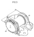
- FIG. 3 shows an embodiment for a belt retractor in which the Mechanism side 40 (side with the sensor device 50) from the Spring cassette connection plate and the belt retractor spring cassette cover 60 separately is; the sensor device 50 and the belt retractor spring cassette cover are specific 60 arranged on different sides of the belt retractor.
- the belt retractor spring cassette cover 60 is thus designed such that it both on the mechanism side 40 - and thus on the outside of the sensor device 50 - Can also be mounted on the opposite side 30.
- FIGS. 4a and 4b each show a three-dimensional representation, like the belt retractor spring cassette cover 60 according to FIG. 3 or the belt retractor spring cassette cover can be constructed according to Figures 1 and 2 in the "interior".
- a mainspring 200 can be seen, which is held in a spring heart 210.
- FIG. 5 shows the belt retractor spring cassette cover 60 according to FIGS. 4a and 4a 4b shown again in a detailed representation.
- FIG. 5 shows specifically Construction drawings of the belt retractor spring cassette cover 60 with different cross sections and views.
- the belt retractor spring cassette cover 60 already attached to a spring cassette connection plate 300, which will later be attached to the belt retractor.
- FIG. 5 also shows the mainspring 200, which is held in the spring heart 210.
- the attachment of the mainspring 200 in the spring heart 210 is shown in detail in detail.
Landscapes
- Engineering & Computer Science (AREA)
- Mechanical Engineering (AREA)
- Automotive Seat Belt Assembly (AREA)
Abstract
Description
- Fig. 1
- ein erstes Ausführungsbeispiel für einen erfindungsgemäßen Gurtaufroller, bei dem ein Ausführungsbeispiel für einen erfindungsgemäßen Gurtaufroller-Federkassettendeckel auf derselben Seite wie eine Sensor-Vorrichtung des Gurtaufrollers montiert ist,
- Fig. 2
- ein zweites Ausführungsbeispiel für einen erfindungsgemäßen Gurtaufroller, bei dem ein Ausführungsbeispiel für einen erfindungsgemäßen Gurtaufroller-Federkassettendeckel auf derselben Seite wie eine Sensor-Vorrichtung des Gurtaufrollers montiert ist,
- Fig. 3
- ein drittes Ausführungsbeispiel für einen erfindungsgemäßen Gurtaufroller, bei dem die Sensor-Vorrichtung des Gurtaufrollers und die Federkassetten-Seite des Gurtaufrollers auf unterschiedlichen Seiten liegen,
- Fig. 4a und 4b
- ein Ausführungsbeispiel für einen erfindungsgemäßen Gurtaufroller-Federkassettendeckel und
- Fig. 5
- Konstruktionszeichnungen für den Gurtaufroller-Federkassettendeckel gemäß Figuren 4a und 4b im Detail.
| Bezugszeichenliste | |
| 10 | Gurtaufroller |
| 20 | Straffeinrichtung |
| 30 | Eine Seite des Gurtaufrollers |
| 40 | Mechanismusseite bzw. -platte des Gurtaufrollers |
| 50 | Sensor-Vorrichtung |
| 60 | Gurtaufroller-Federkassettendeckel |
| 200 | Triebfeder |
| 210 | Federherz |
| 300 | Federkassettenanschlussplatte |
Claims (10)
- Gurtaufroller-Federkassettengehäuse (60) mit einem Federherz (210) und einer Triebfeder (200), die in dem Federherz (210) gehalten wird, wobei das Gurtaufroller-Federkassettengehäuse (10) und/oder das Federherz (200) derart symmetrisch ausgestaltet sind, dass die Triebfeder (200) eine beliebige Drehmomentrichtung aufweisen kann.
- Gurtaufroller-Federkassettengehäuse nach Anspruch 1, dadurch gekennzeichnet, dass das Gurtaufroller-Federkassettengehäuse durch einen Gurtaufroller-Federkassettendeckel (60) gebildet ist.
- Gurtaufroller (10) mit einer Federkassettenanschlussplatte (300), die derart ausgestaltet ist, dass ein Gurtaufroller-Federkassettengehäuse (60) nach Anspruch 1 oder 2 anschließbar ist.
- Gurtaufroller nach Anspruch 3, dadurch gekennzeichnet, dass die Federkassettenanschlussplatte (300) einen derartig symmetrischen Aufbau aufweist, dass ein Gurtaufroller-Federkassettengehäuse nach Anspruch 1 oder 2 mit beliebiger Federdrehmomentrichtung anschließbar ist.
- Gurtaufroller nach Anspruch 4, dadurch gekennzeichnet, dass der Gurtaufroller (10) derart ausgestaltet ist, dass beliebige Gurtaufroll-Drehrichtungen der Gurtspindel möglich sind und die Gurtaufrollrichtung des Gurtaufrollers ausschließlich durch die Drehmomentrichtung der Triebfeder (200) bestimmt ist.
- Gurtaufroller nach einem der vorangehenden Ansprüche, dadurch gekennzeichnet, dass der Gurtaufroller (10) mindestens eine Sensor-Vorrichtung, insbesondere eine Gurtband-Sensoreinrichtung und/oder einen Fahrzeugsensor, aufweist.
- Gurtaufroller nach Anspruch 6, dadurch gekennzeichnet, dass die Sensor-Vorrichtung (50) derart ausgestaltet ist, dass ein Gurtaufroller-Federkassettengehäuse (60) nach Anspruch 1 oder 2 daran montierbar ist.
- Gurtaufroller nach Anspruch 7, dadurch gekennzeichnet, dass die Sensor-Vorrichtung (50) derart ausgestaltet ist, dass bei einer Montage des Gurtaufroller-Federkassettengehäuses nach Anspruch 1 oder 2 eine Kraftübertragung zwischen der Triebfeder (200) des Gurtaufroller-Federkassettengehäuses und der Gurtspindel des Gurtaufrollers gewährleistet ist.
- Gurtaufroller nach einem der vorangehenden Ansprüche, dadurch gekennzeichnet, dass die Federkassettenanschlussplatte (300) durch eine Außenseite der Sensor-Vorrichtung (50) gebildet ist.
- Gurtaufroller, nach einem der vorangehenden Ansprüche 2 bis 8, dadurch gekennzeichnet, dass die Sensor-Vorrichtung (50) und die Federkassettenanschlussplatte (300) auf unterschiedlichen Seiten des Gurtaufrollers angeordnet sind.
Applications Claiming Priority (2)
| Application Number | Priority Date | Filing Date | Title |
|---|---|---|---|
| DE10320836A DE10320836A1 (de) | 2003-05-08 | 2003-05-08 | Gurtaufroller und Gurtaufroller-Federkassettengehäuse für einen Gurtaufroller |
| DE10320836 | 2003-05-08 |
Publications (2)
| Publication Number | Publication Date |
|---|---|
| EP1475281A1 true EP1475281A1 (de) | 2004-11-10 |
| EP1475281B1 EP1475281B1 (de) | 2006-08-09 |
Family
ID=32981305
Family Applications (1)
| Application Number | Title | Priority Date | Filing Date |
|---|---|---|---|
| EP04090158A Expired - Fee Related EP1475281B1 (de) | 2003-05-08 | 2004-04-22 | Gurtaufroller und Gurtaufroller-Federkassettengehäuse für einen Gurtaufroller |
Country Status (5)
| Country | Link |
|---|---|
| US (1) | US7309041B2 (de) |
| EP (1) | EP1475281B1 (de) |
| JP (1) | JP4559773B2 (de) |
| CN (1) | CN1550384B (de) |
| DE (2) | DE10320836A1 (de) |
Families Citing this family (4)
| Publication number | Priority date | Publication date | Assignee | Title |
|---|---|---|---|---|
| DE10043601A1 (de) * | 2000-09-01 | 2002-03-14 | Aixtron Ag | Vorrichtung und Verfahren zum Abscheiden insbesondere kristalliner Schichten auf insbesondere kristallinen Substraten |
| JP2006290087A (ja) * | 2005-04-08 | 2006-10-26 | Takata Corp | シートベルトリトラクタおよびこれを備えたシートベルト装置 |
| JP2006290124A (ja) * | 2005-04-08 | 2006-10-26 | Takata Corp | シートベルトリトラクタおよびこれを備えたシートベルト装置 |
| KR101715969B1 (ko) * | 2009-08-22 | 2017-03-13 | 아돌프 폴 게엠베하 + 씨오. 카게 | 안전 벨트용 벨트 리트랙터 |
Citations (4)
| Publication number | Priority date | Publication date | Assignee | Title |
|---|---|---|---|---|
| DE2900104A1 (de) * | 1978-01-06 | 1979-07-12 | American Safety Equip | Gehaeusezusammenstellung fuer eine vorgespannte feder einer sicherheitsgurteinziehvorrichtung |
| US4340191A (en) * | 1980-09-26 | 1982-07-20 | Barnes Group Inc. | Seat belt retractor spring assembly |
| EP0115919A2 (de) * | 1983-02-03 | 1984-08-15 | BRITAX-KOLB GMBH & CO | Sicherheitsgurtaufroller mit Notsperre |
| US4776574A (en) * | 1985-11-07 | 1988-10-11 | General Safety Corporation | Seat belt retractor rewind spring assembly |
Family Cites Families (10)
| Publication number | Priority date | Publication date | Assignee | Title |
|---|---|---|---|---|
| US4301977A (en) * | 1979-12-03 | 1981-11-24 | Pacific Scientific Company | Dual tension strap retractor |
| JPS58185351A (ja) * | 1982-04-26 | 1983-10-29 | Nissan Motor Co Ltd | シ−トベルトリトラクタ |
| JPH02283547A (ja) * | 1989-04-21 | 1990-11-21 | Fuji Auto Ribu Kk | シートベルトリトラクタ |
| JPH0742882Y2 (ja) * | 1989-12-27 | 1995-10-04 | 富士オートリブ株式会社 | 渦巻きばねの懸架構造 |
| JP2870957B2 (ja) * | 1990-03-28 | 1999-03-17 | アイシン精機株式会社 | シートベルト巻取装置 |
| US5411222A (en) * | 1993-09-23 | 1995-05-02 | Trw Vehicle Safety Systems Limited | Seat belt retractor with tension controller |
| US5443223A (en) * | 1993-10-26 | 1995-08-22 | Trw Vehicle Safety Systems Inc. | Structure for use in a seat belt retractor and method of using the structure to make a seat belt retractor |
| DE19611748C2 (de) * | 1996-03-25 | 1998-03-26 | Autoliv Dev | Sicherheitsgurtaufroller mit Komfortfunktion |
| JPH10167007A (ja) * | 1996-12-16 | 1998-06-23 | Takata Kk | シートベルトリトラクタ |
| GB2360019B (en) * | 1999-03-31 | 2001-11-28 | Breed Automotive Tech | Retractor |
-
2003
- 2003-05-08 DE DE10320836A patent/DE10320836A1/de not_active Withdrawn
-
2004
- 2004-04-22 DE DE502004001132T patent/DE502004001132D1/de not_active Expired - Lifetime
- 2004-04-22 EP EP04090158A patent/EP1475281B1/de not_active Expired - Fee Related
- 2004-05-07 JP JP2004166410A patent/JP4559773B2/ja not_active Expired - Fee Related
- 2004-05-08 CN CN2004100385903A patent/CN1550384B/zh not_active Expired - Fee Related
- 2004-05-10 US US10/841,839 patent/US7309041B2/en not_active Expired - Fee Related
Patent Citations (4)
| Publication number | Priority date | Publication date | Assignee | Title |
|---|---|---|---|---|
| DE2900104A1 (de) * | 1978-01-06 | 1979-07-12 | American Safety Equip | Gehaeusezusammenstellung fuer eine vorgespannte feder einer sicherheitsgurteinziehvorrichtung |
| US4340191A (en) * | 1980-09-26 | 1982-07-20 | Barnes Group Inc. | Seat belt retractor spring assembly |
| EP0115919A2 (de) * | 1983-02-03 | 1984-08-15 | BRITAX-KOLB GMBH & CO | Sicherheitsgurtaufroller mit Notsperre |
| US4776574A (en) * | 1985-11-07 | 1988-10-11 | General Safety Corporation | Seat belt retractor rewind spring assembly |
Also Published As
| Publication number | Publication date |
|---|---|
| JP4559773B2 (ja) | 2010-10-13 |
| CN1550384A (zh) | 2004-12-01 |
| US20050023402A1 (en) | 2005-02-03 |
| JP2004331070A (ja) | 2004-11-25 |
| DE10320836A1 (de) | 2004-12-02 |
| US7309041B2 (en) | 2007-12-18 |
| EP1475281B1 (de) | 2006-08-09 |
| DE502004001132D1 (de) | 2006-09-21 |
| CN1550384B (zh) | 2011-09-14 |
Similar Documents
| Publication | Publication Date | Title |
|---|---|---|
| DE69825697T2 (de) | Haltevorrichtung eines Abdeckrollos | |
| DE69926777T2 (de) | Fensterhebemechanismus | |
| EP1404956B1 (de) | Elektromotorischer antrieb mit einer schnecke | |
| EP1819574A1 (de) | Lenkung mit einem elektromotor zur lenkkraftunterstuetzung | |
| DE3108612A1 (de) | Anschnallgurt-aufwickeleinrichtung mit spannungsunterdruecker | |
| DE10058933A1 (de) | Sicherheitsgurtrückholer | |
| DE602006000151T2 (de) | Sicherheitsgurt-Aufroller und Sicherheitsgurtvorrichtung mit einem derartigen Sicherheitsgurt-Aufroller | |
| DE102017111398A1 (de) | Gurtaufroller und Verfahren zur Steuerung eines Gurtaufrollers | |
| DE843630C (de) | Sicherungsring | |
| DE69836280T2 (de) | Rückenlehne für einen fahrzeugsitz | |
| DE602006000439T2 (de) | Sicherheitsgurt-Aufroller und Sicherheitsgurtvorrichtung mit einem derartigen Sicherheitsgurt-Aufroller | |
| DE60219695T2 (de) | Sicherheitsgurtaufroller | |
| EP1475281A1 (de) | Gurtaufroller und Gurtaufroller-Federkassettengehäuse für einen Gurtaufroller | |
| DE102006036283A1 (de) | Einstellmechanismus zur Längeneinstellung eines Bowdenzugs | |
| WO2003039299A1 (de) | Vorrichtung zur verstellung einer sitzkomponente | |
| DE102020202523A1 (de) | Verstelleinrichtung für einen Fahrzeugsitz | |
| EP1524160B1 (de) | Gurtaufroller für einen Fahrzeug-Sicherheitsgurt | |
| DE102018202390A1 (de) | Kraftfahrzeugsitz, hiermit ausgestattetes Kraftfahrzeug sowie Verfahren zum Einstellen einer Bezugsspannung des Kraftfahrzeugsitzes | |
| DE4036440C2 (de) | Positionseinstelleinrichtung für einen Schultergurt in einer Sitzgurtanordnung | |
| EP1285827A1 (de) | Gurtaufroller für einen Fahrzeugsicherheitsgurt | |
| DE102020207557B3 (de) | Gurtaufroller | |
| DE202011005331U1 (de) | Positionierungsvorrichtung für Fahrzeugtüren | |
| DE102020213193A1 (de) | Seilantriebsvorrichtung eines Kraftfahrzeugs | |
| DE19961108B4 (de) | Gurtaufroller für einen Sicherheitsgurt in einem Fahrzeug | |
| DE202019105528U1 (de) | Sitzbezugselement für einen Fahrzeugsitz, Verwendung eines solchen Sitzbezugselements und Fahrzeugsitz |
Legal Events
| Date | Code | Title | Description |
|---|---|---|---|
| PUAI | Public reference made under article 153(3) epc to a published international application that has entered the european phase |
Free format text: ORIGINAL CODE: 0009012 |
|
| AK | Designated contracting states |
Kind code of ref document: A1 Designated state(s): AT BE BG CH CY CZ DE DK EE ES FI FR GB GR HU IE IT LI LU MC NL PL PT RO SE SI SK TR |
|
| AX | Request for extension of the european patent |
Extension state: AL HR LT LV MK |
|
| 17P | Request for examination filed |
Effective date: 20050504 |
|
| AKX | Designation fees paid |
Designated state(s): DE FR GB SE |
|
| GRAP | Despatch of communication of intention to grant a patent |
Free format text: ORIGINAL CODE: EPIDOSNIGR1 |
|
| GRAS | Grant fee paid |
Free format text: ORIGINAL CODE: EPIDOSNIGR3 |
|
| GRAA | (expected) grant |
Free format text: ORIGINAL CODE: 0009210 |
|
| AK | Designated contracting states |
Kind code of ref document: B1 Designated state(s): DE FR GB SE |
|
| REG | Reference to a national code |
Ref country code: GB Ref legal event code: FG4D Free format text: NOT ENGLISH |
|
| REF | Corresponds to: |
Ref document number: 502004001132 Country of ref document: DE Date of ref document: 20060921 Kind code of ref document: P |
|
| REG | Reference to a national code |
Ref country code: SE Ref legal event code: TRGR |
|
| GBT | Gb: translation of ep patent filed (gb section 77(6)(a)/1977) |
Effective date: 20061030 |
|
| ET | Fr: translation filed | ||
| PLBE | No opposition filed within time limit |
Free format text: ORIGINAL CODE: 0009261 |
|
| STAA | Information on the status of an ep patent application or granted ep patent |
Free format text: STATUS: NO OPPOSITION FILED WITHIN TIME LIMIT |
|
| 26N | No opposition filed |
Effective date: 20070510 |
|
| PGFP | Annual fee paid to national office [announced via postgrant information from national office to epo] |
Ref country code: SE Payment date: 20130412 Year of fee payment: 10 Ref country code: GB Payment date: 20130417 Year of fee payment: 10 |
|
| REG | Reference to a national code |
Ref country code: SE Ref legal event code: EUG |
|
| GBPC | Gb: european patent ceased through non-payment of renewal fee |
Effective date: 20140422 |
|
| PG25 | Lapsed in a contracting state [announced via postgrant information from national office to epo] |
Ref country code: GB Free format text: LAPSE BECAUSE OF NON-PAYMENT OF DUE FEES Effective date: 20140422 Ref country code: SE Free format text: LAPSE BECAUSE OF NON-PAYMENT OF DUE FEES Effective date: 20140423 |
|
| REG | Reference to a national code |
Ref country code: FR Ref legal event code: PLFP Year of fee payment: 12 |
|
| PGFP | Annual fee paid to national office [announced via postgrant information from national office to epo] |
Ref country code: FR Payment date: 20150408 Year of fee payment: 12 |
|
| REG | Reference to a national code |
Ref country code: FR Ref legal event code: ST Effective date: 20161230 |
|
| PG25 | Lapsed in a contracting state [announced via postgrant information from national office to epo] |
Ref country code: FR Free format text: LAPSE BECAUSE OF NON-PAYMENT OF DUE FEES Effective date: 20160502 |
|
| REG | Reference to a national code |
Ref country code: DE Ref legal event code: R082 Ref document number: 502004001132 Country of ref document: DE Representative=s name: MAIKOWSKI & NINNEMANN PATENTANWAELTE PARTNERSC, DE Ref country code: DE Ref legal event code: R081 Ref document number: 502004001132 Country of ref document: DE Owner name: JOYSON SAFETY SYSTEMS JAPAN K.K., JP Free format text: FORMER OWNER: TAKATA CORP., TOKIO/TOKYO, JP |
|
| PGFP | Annual fee paid to national office [announced via postgrant information from national office to epo] |
Ref country code: DE Payment date: 20180629 Year of fee payment: 15 |
|
| REG | Reference to a national code |
Ref country code: DE Ref legal event code: R119 Ref document number: 502004001132 Country of ref document: DE |
|
| PG25 | Lapsed in a contracting state [announced via postgrant information from national office to epo] |
Ref country code: DE Free format text: LAPSE BECAUSE OF NON-PAYMENT OF DUE FEES Effective date: 20191101 |