EP1475115B1 - Trockenpulverinhalator - Google Patents
Trockenpulverinhalator Download PDFInfo
- Publication number
- EP1475115B1 EP1475115B1 EP04018486A EP04018486A EP1475115B1 EP 1475115 B1 EP1475115 B1 EP 1475115B1 EP 04018486 A EP04018486 A EP 04018486A EP 04018486 A EP04018486 A EP 04018486A EP 1475115 B1 EP1475115 B1 EP 1475115B1
- Authority
- EP
- European Patent Office
- Prior art keywords
- holder
- medicator
- blister pack
- medical powder
- inhalant
- Prior art date
- Legal status (The legal status is an assumption and is not a legal conclusion. Google has not performed a legal analysis and makes no representation as to the accuracy of the status listed.)
- Expired - Lifetime
Links
- 229940112141 dry powder inhaler Drugs 0.000 title 1
- 239000000843 powder Substances 0.000 claims description 190
- 238000003860 storage Methods 0.000 claims description 104
- 230000007246 mechanism Effects 0.000 claims description 19
- 238000005304 joining Methods 0.000 claims description 8
- 238000011144 upstream manufacturing Methods 0.000 claims description 4
- 239000003814 drug Substances 0.000 description 41
- 229940079593 drug Drugs 0.000 description 26
- 238000003780 insertion Methods 0.000 description 23
- 230000037431 insertion Effects 0.000 description 23
- 210000004072 lung Anatomy 0.000 description 18
- 230000009471 action Effects 0.000 description 15
- 239000002775 capsule Substances 0.000 description 11
- 239000000463 material Substances 0.000 description 10
- 230000029058 respiratory gaseous exchange Effects 0.000 description 10
- XAGFODPZIPBFFR-UHFFFAOYSA-N aluminium Chemical compound [Al] XAGFODPZIPBFFR-UHFFFAOYSA-N 0.000 description 6
- 229910052782 aluminium Inorganic materials 0.000 description 6
- 229920003002 synthetic resin Polymers 0.000 description 6
- 239000000057 synthetic resin Substances 0.000 description 6
- 238000009833 condensation Methods 0.000 description 5
- 230000005494 condensation Effects 0.000 description 5
- 230000000149 penetrating effect Effects 0.000 description 5
- 238000002483 medication Methods 0.000 description 4
- 230000001965 increasing effect Effects 0.000 description 3
- 210000000214 mouth Anatomy 0.000 description 3
- 239000002245 particle Substances 0.000 description 3
- 210000003437 trachea Anatomy 0.000 description 3
- 239000000443 aerosol Substances 0.000 description 2
- 208000006673 asthma Diseases 0.000 description 2
- 230000000903 blocking effect Effects 0.000 description 2
- 238000004891 communication Methods 0.000 description 2
- 230000002708 enhancing effect Effects 0.000 description 2
- 239000008187 granular material Substances 0.000 description 2
- 230000002401 inhibitory effect Effects 0.000 description 2
- 238000000034 method Methods 0.000 description 2
- 239000000203 mixture Substances 0.000 description 2
- 238000009423 ventilation Methods 0.000 description 2
- 206010011224 Cough Diseases 0.000 description 1
- 238000012387 aerosolization Methods 0.000 description 1
- 230000033228 biological regulation Effects 0.000 description 1
- 230000006835 compression Effects 0.000 description 1
- 238000007906 compression Methods 0.000 description 1
- 230000007423 decrease Effects 0.000 description 1
- 230000000994 depressogenic effect Effects 0.000 description 1
- 238000009792 diffusion process Methods 0.000 description 1
- 239000012530 fluid Substances 0.000 description 1
- 239000008263 liquid aerosol Substances 0.000 description 1
- 238000004519 manufacturing process Methods 0.000 description 1
- 230000004048 modification Effects 0.000 description 1
- 238000012986 modification Methods 0.000 description 1
- 230000002093 peripheral effect Effects 0.000 description 1
Images


Classifications
-
- A—HUMAN NECESSITIES
- A61—MEDICAL OR VETERINARY SCIENCE; HYGIENE
- A61M—DEVICES FOR INTRODUCING MEDIA INTO, OR ONTO, THE BODY; DEVICES FOR TRANSDUCING BODY MEDIA OR FOR TAKING MEDIA FROM THE BODY; DEVICES FOR PRODUCING OR ENDING SLEEP OR STUPOR
- A61M15/00—Inhalators
- A61M15/0028—Inhalators using prepacked dosages, one for each application, e.g. capsules to be perforated or broken-up
- A61M15/0045—Inhalators using prepacked dosages, one for each application, e.g. capsules to be perforated or broken-up using multiple prepacked dosages on a same carrier, e.g. blisters
-
- A—HUMAN NECESSITIES
- A61—MEDICAL OR VETERINARY SCIENCE; HYGIENE
- A61M—DEVICES FOR INTRODUCING MEDIA INTO, OR ONTO, THE BODY; DEVICES FOR TRANSDUCING BODY MEDIA OR FOR TAKING MEDIA FROM THE BODY; DEVICES FOR PRODUCING OR ENDING SLEEP OR STUPOR
- A61M11/00—Sprayers or atomisers specially adapted for therapeutic purposes
- A61M11/001—Particle size control
- A61M11/002—Particle size control by flow deviation causing inertial separation of transported particles
-
- A—HUMAN NECESSITIES
- A61—MEDICAL OR VETERINARY SCIENCE; HYGIENE
- A61M—DEVICES FOR INTRODUCING MEDIA INTO, OR ONTO, THE BODY; DEVICES FOR TRANSDUCING BODY MEDIA OR FOR TAKING MEDIA FROM THE BODY; DEVICES FOR PRODUCING OR ENDING SLEEP OR STUPOR
- A61M15/00—Inhalators
- A61M15/0028—Inhalators using prepacked dosages, one for each application, e.g. capsules to be perforated or broken-up
- A61M15/003—Inhalators using prepacked dosages, one for each application, e.g. capsules to be perforated or broken-up using capsules, e.g. to be perforated or broken-up
- A61M15/0033—Details of the piercing or cutting means
- A61M15/0035—Piercing means
-
- A—HUMAN NECESSITIES
- A61—MEDICAL OR VETERINARY SCIENCE; HYGIENE
- A61M—DEVICES FOR INTRODUCING MEDIA INTO, OR ONTO, THE BODY; DEVICES FOR TRANSDUCING BODY MEDIA OR FOR TAKING MEDIA FROM THE BODY; DEVICES FOR PRODUCING OR ENDING SLEEP OR STUPOR
- A61M15/00—Inhalators
- A61M15/0028—Inhalators using prepacked dosages, one for each application, e.g. capsules to be perforated or broken-up
- A61M15/0045—Inhalators using prepacked dosages, one for each application, e.g. capsules to be perforated or broken-up using multiple prepacked dosages on a same carrier, e.g. blisters
- A61M15/0046—Inhalators using prepacked dosages, one for each application, e.g. capsules to be perforated or broken-up using multiple prepacked dosages on a same carrier, e.g. blisters characterized by the type of carrier
- A61M15/0048—Inhalators using prepacked dosages, one for each application, e.g. capsules to be perforated or broken-up using multiple prepacked dosages on a same carrier, e.g. blisters characterized by the type of carrier the dosages being arranged in a plane, e.g. on diskettes
-
- A—HUMAN NECESSITIES
- A61—MEDICAL OR VETERINARY SCIENCE; HYGIENE
- A61M—DEVICES FOR INTRODUCING MEDIA INTO, OR ONTO, THE BODY; DEVICES FOR TRANSDUCING BODY MEDIA OR FOR TAKING MEDIA FROM THE BODY; DEVICES FOR PRODUCING OR ENDING SLEEP OR STUPOR
- A61M2202/00—Special media to be introduced, removed or treated
- A61M2202/06—Solids
- A61M2202/064—Powder
-
- A—HUMAN NECESSITIES
- A61—MEDICAL OR VETERINARY SCIENCE; HYGIENE
- A61M—DEVICES FOR INTRODUCING MEDIA INTO, OR ONTO, THE BODY; DEVICES FOR TRANSDUCING BODY MEDIA OR FOR TAKING MEDIA FROM THE BODY; DEVICES FOR PRODUCING OR ENDING SLEEP OR STUPOR
- A61M2206/00—Characteristics of a physical parameter; associated device therefor
- A61M2206/10—Flow characteristics
- A61M2206/16—Rotating swirling helical flow, e.g. by tangential inflows
Definitions
- the present invention relates to an inhalant medicator suitable to prescribe granular or powdered medicines toward within lungs of a patient by way of breathing action of the patient.
- an inhalant medicator used for an inhalation treatment where a dose of medical powder is inhaled is generally constructed by a medicator body including a capsule housing chamber (or a medical powder storage chamber) at one axial end and equipped at the other axial end with an inhalant port through which the medical powder is inhaled, an air passageway communicating the inhalant port with the atmosphere via the capsule housing chamber, and a pricking tool which provided for pricking holes in the capsule accommodated in the capsule housing chamber.
- inhalant medicators utilizing a blister pack having a set of blisters (a plurality of blistered medical powder storage chambers) spaced apart from each other in the circumferential direction, for inhalant medication.
- Such inhalant medicators have been disclosed in Japanese Patent Provisional Publication Nos. 59-88158 and 62-41668 .
- the inhalant medicator as disclosed in the Japanese Patent Provisional Publication Nos. 59-88158 and 62-41668 includes a blister pack holder which holds a blister pack having a plurality of blisters circumferentially spaced apart from each other.
- the blister pack holder is rotatably mounted to a medicator body.
- the blister pack installed on the holder consists of a base panel formed with a large number of blistered portions, a lid panel affixed onto the principal surface of the base panel and defining a plurality of medical powder storage chambers by hermetically covering the blistered portions of the base panel.
- a dose of medical powder is stored in each of the medical powder storage chambers.
- the blister pack is installed on the pack holder of the inhalant medicator.
- holes needed to intercommunicate the atmospheric side and the inhalant port via the internal space of the medical powder storage chamber are pricked by means of a single plunger having a needle-shaped pricking tip.
- US 5,533,502 A discloses an apparatus for generating respirable aerosol internal to a selected one of a plurality of medicament receptacles containing pre-measured amounts of powdered medicament is disclosed herein.
- the receptacles are disposed in a medicament carrier contained within a housing, and are sealed from exposure to the outside environment.
- the medicament carrier is preferably a ring-shaped member detachably coupled to a carriage which can be rotated to any one of a plurality of selected positions.
- a pair of aerosolization conduits having ends capable of puncturing the seal covering the medicament receptacle selected by the patient are also provided.
- US 5,715,810 A discloses a device for oral or nasal inhalation comprising a body member having a first passageway therethrough, a first end of said first passageway for insertion into a mouth or nose of a user and a second end of said first passageway for intake of air responsive to a user's inhalation, a holder connected to the body member between the first and seconds of the first passageway for receiving a container in an opening defined therein with a second passageway defined through the holder a first end of said second passageway communicating with the first passageway and a second end of said second passageway extending to an exterior of the body member for intake of air responsive to a user's inhalation, and at least one piercer positioned in the second passageway, wherein, air drawn through the first and second passageways is mixed before exiting the first end of the first passageway.
- WO 99/047199 A1 concerns an inhalation activated inhaler having a primary inhalation passage, a secondary inhalation passage disposed in communication with the primary inhalation passage, and a source of medicament.
- the primary inhalation passage has inflow inhibiting mechanism connected to a blocking plate positioned to selectively block fluid flow in the secondary inhalation passage.
- the flow inhibiting mechanism restricts flow through the primary inhalation passage, and moves the blocking plate to enable airflow through the secondary passage.
- the medicament is provided through the secondary inhalation passage, thereby optimizing the delivery of medicament to the lungs.
- EP 0 711 572 A discloses a suction piece provided with an inhaling port and a holder housing member.
- a capsule holder is provided with a capsule housing bore, axially extending ventilation passages, and pin insert holes communicating with these ventilation passages and extending in the radial direction.
- the invention provides an inhalant medicator, which is capable of prescribing a specified amount of medical powder toward within lungs of a patient, while satisfactorily diffusing the medical powder stored in a medical powder storage chamber of a blister pack.
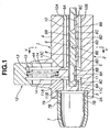
- FIG. 1 there are shown the inhalant medicator of the first embodiment and a blister pack 16 applied to the inhalant medicator of the first embodiment.
- reference sign 1 denotes an inhalant medicator assembly.
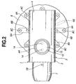
- the inhalant medicator assembly 1 is mainly constructed by a medicator body 2 and an inhalant port 7. As described later, the medicator body 2 is formed therein with a plurality of air passageways, and also serves as a blister pack holder mounting portion for a blister pack 16 which will be fully described later. As best seen in Figs. 3 through 5, as a whole, the medicator body 2 is substantially cylindrical in shape.
- the medicator body 2 is comprised of an upper medicator-body portion 4 having a substantially semi-circular cross section, a lower medicator-body portion 5 having a substantially semi-circular cross section (see Figs. 3 and 5), and a substantially cylindrical joining portion 3 through which the upper and lower medicator-body portions 4 and 5 are formed integral with each other.
- Joining portion 3 has an internal thread portion 3A into which an external thread portion 7A of the inhalant port 7 is screwed.
- Upper and lower medicator-body portions 4 and 5, each having the substantially semi-circular cross section, are constructed in such a manner as to axially extend from the joining portion 3, so that their opposed flat surfaces, namely a ceiling wall surface 6B of a holder mounting groove 6 (described later) and a bottom surface 6C of the holder mounting groove 6, are parallel to each other and spaced apart from each other by a predetermined aperture (see Figs. 3 and 5).
- Medicator body 2 is also formed with the blister pack holder mounting groove 6 defined between upper and lower medicator-body portions 4 and 5. As a whole, the medicator body 2 is substantially cylindrical in shape. As clearly shown in Figs.
- the upper medicator-body portion 4 is formed with a pricking tool guide 4A capable of slidably supporting or guiding a support portion 13 of a pricking tool (pricking means) 12 (described later).
- the holder mounting groove 6 is defined between upper and lower medicator-body portions 4 and 5 by three surfaces, namely an innermost end surface 6A forming part of the joining portion 3, the ceiling wall surface 6B corresponding to the underside of upper medicator-body portion 4, and the bottom surface 6C corresponding to the upside of lower medicator-body portion 5.
- the holder mounting groove 6 opens to three directions, that is, leftwards and rightwards, and in one axial direction of the medicator body.
- the innermost end surface 6A of the groove 6 is formed into a concave circular-arc shape that fits the contour of the outer periphery of a blister pack holder 8 (see Fig. 4).
- the predetermined aperture defined between the ceiling wall surface 6B and the bottom surface 6C is dimensioned to be somewhat greater than the thickness dimension of the holder 8 (see Fig. 1).
- the lower medicator-body portion 5 is formed with a protruded portion 6D extending upwards from a substantially central portion of the bottom surface 6C of holder mounting groove 6, such that the axis of the protruded portion 6D is perpendicular to the bottom surface 6C.
- the protruded portion 6D functions as a center of rotation (or an axis of rotation) of the blister pack holder 8.
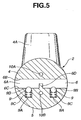
- Inhalant port 7 is screwed into the other axial end of medicator body 2, and is substantially cylindrical hollow in shape.
- the top end (the left-hand side axial end of the inhalant medicator assembly 1 shown in Fig. 1) of inhalant port 7 is configured in a manner so as to gradually diametrically small-sized in the other axial direction.
- the root portion of inhalant port 7 is formed nearby the external thread portion 7A with a plurality of radially-extending auxiliary air passageways 7B. 7B, ... (only two auxiliary air passageways 7B and 7B are shown in Fig.
- Each of the auxiliary air passageways 7B serves to avoid difficulty in breathing action by increasing a quantity of air flowing through the inhalant medicator during the breathing action.
- the inhalant port 7 is installed on the other axial end of the medicator body by screwing the external thread portion 7A of inhalant port 7 into the internal thread portion 3A of joining portion 3 of the medicator body.
- the blister pack holder 8 is detachably rotatably mounted into the groove 6 of medicator body 2, so that the disc-shaped holder 8 is easily inserted into and removed from within the groove 6.
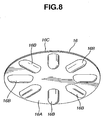
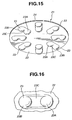
- the holder 8 When the innermost end of the guide groove 8E of the holder engages with the protruded portion 6D of the medicator body, the holder 8 is rotatable about the protruded portion 6D. As clearly shown in Figs. 6 and 7, the holder 8 has a substantially disc shape. As can be seen from the top view shown in Fig. 6, the holder 8 is formed on its upside with eight recessed fit portions 8A, 8A, ..., 8A circumferentially spaced apart from each other by 45 degrees and located near its circumference. In the inhalant medicator of the first embodiment, the eight recessed fit portions 8A are configured or formed as eight radially-elongated, substantially semi-cylindrical cavities.
- Eight blistered portions 16B of blister pack 16 are integrally fitted into the respective eight recessed fit portions 8A of holder 8.
- the holder 8 is formed in each of recessed fit portions 8A with an inflow pin insertion hole (a radially inward pin insertion hole) 8B and an outflow pin insertion hole (a radially-outward pin insertion hole) 8C spaced apart from each other in the radial direction of the holder 8 (viewing Fig. 6), so that two pin insertion holes 8B and 8C penetrate the disc-shaped holder 8 in a direction perpendicular to upper and lower surfaces of the holder 8. As viewed from the top view of Fig.
- recessed fit portions 8A eight pairs of radially-aligned inward and outward pin insertion holes (8B, 8C) are also circumferentially spaced apart from each other by 45 degrees.
- the holder 8 is also formed with eight recessed fit portions 8D, 8D, ..., 8D.
- the recessed fit portions 8D are formed as eight small spherical bowl cavities.
- the number of the recessed fit portions 8D is an even number, for easy but reliable engagement between one diametrically-opposed pair (8D, 8D) of the eight recessed fit portions and a pair of spring-loaded balls (9A, 9A) of a positioning mechanism 9 (described later).
- a positioning mechanism (positioning means) 9 is provided between the holder 8 and the blister pack holder mounting portion of the medicator body for positioning one of the medical powder storage chambers of the blister pack installed or held on the holder 8 at a predetermined pricking position.
- a pair of spherical ball portions (9B, 9B) included in the positioning mechanism 9 are easily fitted to one diametrically-opposed pair (8D, 8D) of the eight recessed fit portions.
- Such easy fit between two spherical ball portions (9B, 9B) and diametrically-opposed pair (8D, 8D) ensures easy rotation of the holder 8 about the protruded portion 6D (serving as the axis of rotation of the holder 8) and is produced by proper mechanical snap action during rotary motion of the holder.
- two spherical ball portions (9B, 9B) are comprised of spring-loaded balls included in the positioning mechanism 9 (described later).
- the eight recessed fit portions 8D are located around the center of the holder 8.
- Each of recessed fit portions 8D is located on a straight line including two centers of the associated radially-aligned inward and outward pin insertion holes 8B and 8C.
- the eight recessed fit portions 8D are also circumferentially spaced apart from each other by 45 degrees.
- the holder 8 is also formed on the underside with the guide groove 8E radially extending from the center of rotation of the holder 8.
- the guide groove 8E is formed to guide the protruded portion 6D of the holder mounting groove 6 toward the center of rotation of the holder 8.
- the holder 8 is inserted or mounted into the holder mounting groove 6 in accordance with the following procedures.
- the guide groove 8E is engaged with the protruded portion 6D under a condition where the blister pack 16 is installed on and fitted to the upside of the holder 8. Thereafter, the holder 8 installing thereon the blister pack 16, is inserted into the holder mounting groove 6 of medicator body 2. until the innermost end of the guide groove 8E of the holder reaches the protruded portion 6D of the medicator body.
- a component part denoted by 9 is the positioning mechanism (or positioning means).
- the positioning mechanism 9 includes a pair of spring-loaded ball housing bores (9A, 9A) each closed at one end.
- the bores (9A, 9A) are point-symmetrical with respect to the protruded portion 6D and formed in the bottom surface 6C (lower medicator-body portion 5) of holder mounting groove 6.
- the positioning mechanism 9 also includes two spring-loaded spherical balls (9B, 9B) housed in the respective ball housing bores (9A, 9A) in an unremovable fashion so that the inside diameter of the opening end of each spring-loaded ball housing bore 9A is slightly less than the inside diameter of the other portion of the bore 9A, and two coil springs (9C, 9C), each operably disposed in the ball housing bore 9A in a manner so as to permanently bias the associated ball 9B in a direction that causes a part of the spherical surface of the ball 9B to be slightly protruded from the bottom surface 6C through an opening end of the bore 9A into the groove 6 of medicator body 2.
- the positioning mechanism 9 is comprised of a snap-action mechanism with a pair of spring-loaded balls (9B, 9B).
- the two spring-loaded balls (9B, 9B) can be brought into engagement with the respective recessed fit portions (8D, 8D) of the holder 8.
- one of eight radially-elongated recessed fit portions 8A (that is, one of eight medical powder storage chambers 16D of blister pack 16) is efficiently reliably positioned in a predetermined pricking position of the pricking tool 12 (or in a set position for inhalant medication).
- Reference sign 10 denotes an inflow air passageway through which the atmosphere (outside air) can be introduced into or directed toward within the recessed fit portion 8A of the holder 8.
- the inflow air passageway 10 includes an upper axially-extending air passage 10A which is bored or formed in the upper medicator-body portion 4, and whose one axial end opens at one axial end of the upper medicator-body portion 4 to the atmosphere.
- the inflow air passageway 10 includes a lower axially-extending air passage 10B which is bored or formed in the lower medicator-body portion 5, and whose one axial end opens at one axial end of the lower medicator-body portion 5 to the atmosphere.
- the inflow air passageway 10 also includes a radially-extending pin insertion hole 10C formed in the medicator body 2 so that the pin insertion hole 10C radially extends from the pricking tool guide 4A via the upper medicator-body portion 4 toward the lower medicator-body portion 5.
- the radially-extending pin insertion hole 10C is fluidly communicated with the other axial end of each of the upper and lower axially-extending air passages 10A and 10B.
- the pin insertion hole 10C is designed to communicate with the inflow pin insertion hole 8B of the holder 8, when one of eight recessed fit portions 8A of the holder 8 is positioned in the pricking position.
- reference sign 11 denotes an outflow air passageway through which medical powder stored in the medical powder storage chamber 16D of the blister pack 16 flows into the inhalant port 7.
- the outflow air passageway 11 includes a pin insertion hole 11A, an upper outflow air passage 11B, and a lower outflow air passage 11C.
- the pin insertion hole 11A radially extends in parallel with the pin insertion hole 10C of the inflow air passageway 10.
- the upper outflow air passage 11B axially extends from the upper medicator-body portion 4 via the joining portion 3 toward the inhalant port 7.
- One axial end of the upper outflow air passage 11B is fluidly communicated with the pin insertion hole 11A, whereas the other axial end opens to the interior space of the inhalant port 7.
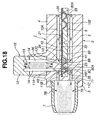
- a component part denoted by reference sign 12 is the pricking tool used to prick holes in the blister pack 16.
- the pricking tool 12 includes the support portion 13 whose outer periphery is slidably supported or guided by a cylindrical inner peripheral wall of the pricking tool guide 4A, and a pair of parallel pins (14, 14) whose root portions are fixedly connected to the support portion 13, and whose tips are inserted into the respective pin insertion holes 10C and 11A.
- the pair of parallel pins are spaced apart from each other by a predetermined distance smaller than a longitudinal length of each of the blistered portions of the blister pack.
- the pricking tool 12 also includes a return spring 15 operably disposed between the support portion 13 and the upper medicator-body portion 4 for permanently biasing the support portion 13 and the pins (14, 14) toward their initial positions.
- a patient pushes the support portion 13 of pricking tool 12 into the pricking tool guide 4A against the bias of the spring 15, and thus the two pins (14, 14) are deeply inserted into the respective pin insertion holes 10C and 11A.
- the tips of pins (14, 14) penetrate the blister pack 16.
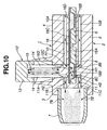
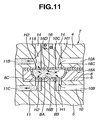
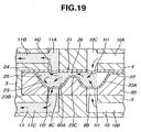
- two inflow holes or two inflow ports (H1, H1) and two outflow holes or two outflow ports (H2, H2) are pricked respectively in the blistered portion 16B of a base panel 16A and a lid panel 16C of blister pack 16 (see Figs. 10 and 11), so that two inflow holes (H1, H1) and two outflow holes (H2, H2) are pricked in a perpendicular to the upper surface of the lid panel of the blister pack, and two inflow holes (H1, H1) and two outflow holes (H2, H2) are spaced apart from each other by a predetermined distance which corresponds to a distance between the downstream end of the inflow air passage and the upstream end of the outflow air passageway.
- eight blistered portions 16B of the base panel 16A define eight medical powder storage chambers 16D in conjunction with the lid panel 16C. After pricking, as soon as the pushing force applied to the support portion 13 is removed, the support portion 13 and the two pins (14, 14) are returned back to their initial positions.
- blister pack 16 is comprised of base panel 16A and lid panel 16C affixed onto the principal surface (or the obverse) of base panel 16A.
- the base panel 16A has a thin-walled disc shape and is made of synthetic resin, aluminum material, or the like.
- the base panel 16A has a plurality of blistered portions 16B, 16B, ..., 16B (in the first embodiment, eight blistered portions) around its entire circumference.
- the lid panel 16C has a thin-walled disc shape and is made of synthetic resin, aluminum material, or the like.
- the blistered portions 16B formed in the base panel 16A are located near the circumference of the base panel 16A, and formed as eight radially-elongated, substantially semi-cylindrical convex portions.
- the eight blistered portions 16B are circumferentially spaced apart from each other by 45 degrees.
- eight medical powder storage chambers 16D are defined between the eight blistered portions 16B of base panel 16A and the lid panel 16C.
- a predetermined amount of medical powder such as granular medicine or powdered medicine is stored in each of the medical powder storage chambers 16D.
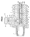
- the inhalant medicator of the first embodiment is constructed as previously discussed. Hereinbelow described in detail in reference to Figs. 9 - 11 are the preliminary operation of inhalant medication through which a patient inhales medical powder, and the flow of air and the flow of medical powder during inhalation.
- blister pack holder 8 is removed from the holder mounting groove 6 of medicator body 2.
- the guide groove 8E formed in the underside of the holder and radially outwardly extending from the center of the holder, must be axially aligned with respect to the axis of the medicator body 2 under a condition in which the outermost end of guide groove 8E faces the inhalant port 7.
- the holder 8 can be removed from the medicator body 2 by pulling the holder 8 against the bias produced by the two spring-loaded balls 9B of the positioning mechanism 9.
- blister pack 16 is fitted to and installed on the upside of holder 8, such that eight blistered portions 16B of the blister pack are fitted to respective recessed fit portions 8A of the holder 8.
- the blister pack 16 can be integrally connected to and reliably positioned with respect to the holder 8, and thus the blister pack 16 is rotatable together with the holder 8.
- the holder 8 is mounted into the holder mounting groove 6.
- the guide groove 8E must be aligned with the axis of the medicator body 2 so that the outermost end of the guide groove 8E is directed toward the inhalant port 7, and also the protruded portion 6D must be engaged with the guide groove 8E.
- two opposed inflow holes (H1, H1) communicating with the inflow air passageway 10 are pricked in the blistered portion 16B of base panel 16A and in the lid panel 16C by means of one of the two pins (14, 14) inserted into the pin insertion hole 10C, and at the same time two opposed outflow holes (H2, H2) communicating with the outflow air passageway 11 are pricked in the blistered portion 16B of base panel 16A and in the lid panel 16C by means of the other pin 14 inserted into the pin insertion hole 11A.
- the medical powder storage chamber 16D of blister pack 16 is communicated through the inflow holes (H1, H1) with the inflow air passageway 10, and also communicated through the outflow holes (H2, H2) with the outflow air passageway 11.
- air atmosphere
- the air flow introduced via the inflow holes (H1, H1) into the medical powder storage chamber 16D is brought into collision with the inner wall surface of medical powder storage chamber 16D, because the inflow holes (H1, H1) and the outflow holes (H2, H2) are spaced apart from each other in the axial direction of the medicator body (or in the longitudinal direction of the blistered portion of the blister pack) by a distance between the two pin insertion holes 8B and 8C, thereby resulting in turbulent flow within the medical powder storage chamber 16D.
- the medical powder stored in the chamber 16D can be effectively diffused or micronized by means of the turbulent flow.
- the inflow holes (H1, H1) communicating with the inflow air passageway 10 and the outflow holes (H2, H2), communicating with the outflow air passageway can be formed or pricked in the blister pack by means of two pins (14, 14) fixedly connected to the pricking tool 12, so that the inflow holes (H1, H1) and the outflow holes (H2, H2) are spaced apart from each other by a predetermined distance corresponding to a distance between the axes of two pins (14, 14).
- air flowing via the inflow holes (H1, H1) toward the outflow holes (H2, H2) is not directed straight, but brought into collision with the inner wall of the medical powder storage chamber.
- Turbulent air flow is thus produced within the medical powder storage chamber by the air flow directed from two inflow holes (H1, H1.) via the internal space of the medical powder storage chamber to two outflow holes (H2, H2). Therefore, it is possible to effectively diffuse or micronize medical powder stored in the medical powder storage chamber by virtue of the turbulent air flow occurring in the medical powder storage chamber owing to the two inflow holes and two outflow holes pricked in both the base panel and lid panel of the blister pack by the two parallel pins during inhalation treatment of air/medical powder mixture. As a result of this, it is possible to efficiently reliably prescribe a specified amount of medical powder pre-stored in one of storage chambers 16D into lungs of a patient by way of breathing action.
- the holder 8 is formed on its underside with the recessed fit portions 8D, and additionally the positioning mechanism 9 is provided in the holder mounting groove 6 for positioning the medical powder storage chamber 16D of blister pack 16 at the predetermined pricking position (the set position for inhalant medication) by fitting the spring-loaded balls (9B, 9B) to the recessed fit portions (8D, 8D).
- the predetermined pricking position the set position for inhalant medication
- the medicator body 2 is constructed by not only upper and lower medicator-body portions 4 and 5, but also joining portion 3 interconnecting the upper and lower medicator-body portions 4 and 5, and also the holder mounting groove 6 is simply defined between the upper and lower medicator-body portions.
- a holder mounting groove structure is so simple.
- the inhalant medicator of the embodiment is designed to be easily assembled by mounting the disc-shaped blister pack holder 8 into the holder mounting groove 6 being simple in structure, thus reducing the number of parts of the inhalant medicator assembly. This ensures ease of assembly, and also reduces total production costs of the inhalant medicator.
- the disc-shaped holder 8 is formed on its upside with circumferentially equally spaced, radially-elongated eight recessed fit portions 8A (eight substantially semi-cylindrical cavities).
- the holder 8 is formed on its underside with the guide groove 8E which is engageable with the protruded portion 6D of holder mounting groove 6.
- the guide groove 8E permits the protruded portion 6D to be reliably easily guided to the rotation center of the holder 8 (the innermost end of the guide groove 8E). This ensures accurate and easy mounting of the holder 8 on the desired position of the medicator body 2, thus ensuring ease of handling.
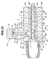
- FIGs. 12 through 19 there are shown the inhalant medicator of the second embodiment and a blister pack 21 applied to the inhalant medicator of the second embodiment.
- the inhalant medicator of the second embodiment of Figs. 12 - 19 is similar to the first embodiment of Figs. 1-11, except that the shape of the blister pack holder 80 and the shape of the blister pack 21 of the second embodiment are different from those of the first embodiment.
- the same reference signs used to designate elements in the first embodiment shown in Figs. 1 - 11 will be applied to the corresponding elements used in the second embodiment shown in Figs. 12 - 19, for the purpose of comparison of the first and second embodiments.
- the blister pack 21 and its holder 80 of the second embodiment will be hereinafter described in detail with reference to the accompanying drawings, while detailed description of elements denoted by the same reference signs will be omitted because the above description thereon seems to be self-explanatory.
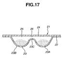
- blister pack 21 is comprised of a base panel 22, a lid panel 24, a medical powder storage chamber 25, and a flow-constriction passage 26.
- Base panel 22 has a thin-walled disc shape and is made of synthetic resin, aluminum material, or the like.
- the base panel has a plurality of blistered portions 23, 23, ..., 23 (in the second embodiment, eight blistered portions) around its entire circumference.
- lid panel 24 has a thin-walled disc shape and is made of synthetic resin, aluminum material, or the like.
- the eight blistered portions 23 are circumferentially spaced apart from each other by 45 degrees. As best seen in Figs.
- the blistered portions 23 formed in the base panel 22 are located near the circumference of the base panel 22, and formed as eight radially-elongated, substantially elliptical convex portions.
- Each of the blistered portions 23 includes a radially-inward, substantially hemispherical convex portion 23A and a radially-outward, substantially hemispherical convex portion 23B, and a flow-constriction portion 23C formed between the two hemispherical convex portions 23A and 23B.
- the flow-constriction portion 23C is configured to provide a flow-constriction orifice passage 26 between the base panel 22 and the lid panel 24 at a connecting point between two convex portions 23A and 23B in close proximity to the inner wall of the lid panel 24.
- the flow-constriction orifice passage 26 is formed in the medical powder storage chamber 25 and arranged between the previously-described inflow holes (H1, H1) and outflow holes (H2, H2).
- the flow-constriction orifice passage 26 functions to increase the flow velocity of air flowing from the inflow holes (H1, H1) via the interior of the medical powder storage chamber 25 to the outflow holes (H2, H2). Additionally, the flow-constriction orifice passage 26 functions to cause proper turbulent flow within the medical powder storage chamber 25 and consequent mixing action.
- the orifice size of the flow-constriction orifice passage 26 depending on characteristics or properties of medical powder used, such as a strong condensation, and a particle size, turbulent air flow suitable to properties of medical powder can be produced. Therefore, it is possible to effectively diffuse the medical powder by virtue of the flow-constriction orifice passage 26 which is dimensioned and designed to be suitable for the properties of medical powder stored in the storage chamber 25.
- the holder 80 is formed on its upside with eight recessed fit portions 80A, 80A, .... 80A circumferentially spaced apart from each other by 45 degrees and located near its circumference.
- the eight recessed fit portions 80A are configured or formed as eight radially-elongated, substantially elliptical cavities.
- Eight blistered portions 23 of blister pack 21 are integrally fitted into the respective eight recessed fit portions 80A of holder 80.
- inhalant medicator of the first embodiment when inhalant medication is initiated using the inhalant medicator of the second embodiment, first, the preliminary operation of inhalant medication is made.
- Inflow holes (H1, H1) and outflow holes (H2, H2) are pricked in the blistered portion 23 of base panel 22 and in the lid panel 24 of blister pack 21 held at the predetermined pricking position, after a series of preliminary setting operations have been completed. Under these conditions, when the patient draws his or her breath while taking the inhalant port 7 in his or her mouse, air flows through the inflow air passage 10 and the inflow holes (H1, H1) into the storage chamber 25.
- the flow-constriction orifice passage 26 is defined within the medical powder storage chamber 25 of blister pack 21 by the flow-constriction portion 23C of blistered portion 23 so that the flow-constriction orifice passage 26 is located between the inflow holes (H1, H1) and the outflow holes (H2, H2).
- the flow-constriction orifice passage 26 acts to properly regulate or control the air flow passing through the medical powder storage chamber 25 depending on the properties or characteristics peculiar to medical powder stored in the storage chamber 25.
- the blister pack 21, storing medical powder has its own flow-constriction orifice passage 26 in each of the blistered portions (or in each of the medical powder storage chambers). Thus, it is possible to easily form a flow-constriction orifice passage suitable for every kind of medical powder, and thereby an efficiency of inhalant medication can be remarkably enhanced.
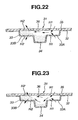
- a modified blister pack 31 As detailed hereunder, the modified blister pack 31 shown in Figs. 20 - 23 is characterized by a deeply-recessed medical powder collecting portion 34, as viewed from the cross section shown in Fig. 21.
- the blister pack 31 is comprised of base panel 32, medical powder collecting portion 34, lid panel 35, and medical powder storage chamber 36.
- the base panel 32 has a thin-walled disc shape and is made of synthetic resin, aluminum material, or the like. As best seen in Fig. 20, the base panel 32 has a plurality of blistered portions 33, 33, ..., 33 (eight blistered portions) around its entire circumference.
- the shape and material of the lid panel 35 of blister pack 31 are identical to those of blister pack 16 applied to the inhalant medicator of the first embodiment (or to those of blister pack 21 applied to the inhalant medicator of the second embodiment).
- the modified blister pack 31 shown in Figs. 20 - 23 is different from the blister pack 21 shown in Figs. 15 - 17, in that the shape of each blistered portion 33 of base panel 32 differs from the shape of each blistered portion 23 of base panel 22.
- the blistered portions 33 are formed as eight radially-elongated, substantially elliptical convex portions.
- Each of the blistered portions 33 includes a radially-inward, shallow pricked portion 33A in which the previously-noted inflow hole H1 is pricked, and a radially-outward, shallow pricked portion 33B in which the previously-noted outflow hole H2 is pricked.
- the medical powder collecting portion 34 is deeply formed or recessed in the base panel 32 midway between the radially-inward, shallow pricked portion 33A and the radially-outward, shallow pricked portion 33B.
- the medical powder collecting portion 34 serves as an air-flow regulation means as described later.
- the medical powder collecting portion 34 of the blistered portion 33 serves as a deeply-recessed medical powder collecting portion kept at a level lower than the shallow pricked portions (33A, 33B).
- a portion denoted by reference sign 36 is the medical powder storage chamber defined between the blistered portion 33 of base panel 32 and the lid panel 35.
- a predetermined amount of medical powder is stored in the medical powder storage chamber 36, such that almost all of the medical powder is collected or pre-stored in the medical powder collecting portion 34.
- the blister pack 31 shown in Figs. 20 - 23 is constructed as previously discussed. Hereinbelow described in detail in reference to Figs.
- Inflow holes (H1, H1) and outflow holes (H2, H2) are pricked in the blistered portion 33 of base panel 32 and in the lid panel 34 of blister pack 31 held at the predetermined pricking position, after a series of preliminary setting operations have been completed.
- air introduced through the inflow air passage 10 via the inflow holes (H1, H1) into the storage chamber 35 functions to fling up and diffuse a part of medical powder located at the top of the medical powder collecting portion 34 (see Fig. 22).
- the upflung and diffused portion of the medical powder collected in the collecting portion 34 is supplied into the outflow holes (H2, H2).
- the medical powder stored in the storage chamber 36 can be gradually reduced.
- air flow passing through the inflow holes (H1, H1) enters the medical powder collecting portion 34, and therefore medical powder collected in the collecting portion 34 is gradually flung up and diffused from the uppermost portion until a lowermost portion of the medical powder stored is flung up, and thus the diffused medical powder is supplied into the outflow holes (H2, H2) little by little.
- the blister pack 31 having the deeply-recessed medical powder collecting portion 34 it is possible to fling up and uniformly diffuse the medical powder stored in the storage chamber 36 little by little. This prevents a large amount of air/medical powder mixture in one breath from being flown into the outflow holes (H2, H2), thus avoiding the outflow holes from being choked up with such a large amount of medical powder flow mass.
- the patient can inhale the medical powder little by little. This prevents the patient from getting a fit of coughing during the inhalant medication, thus ensuring a stable medication during the breathing action.
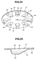
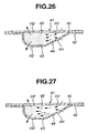
- Figs. 24 through 27 there is shown another modified blister pack 41.
- the modified blister pack 41 shown in Figs. 24 - 27 is characterized by a sloped surface 44, as viewed from the cross section shown in Fig. 25.
- the blister pack 41 is comprised of base panel 42, sloped surface 44, lid panel 45, and medical powder storage chamber 46.
- the blistered portion 43 of blister pack 41 is formed with the previously-noted sloped surface 44 such that a side of the inflow holes (H1, H1) penetrating the radially-inward half of the blistered portion of base panel 42 is formed as a shallow portion, whereas a side of the outflow holes (H2, H2) penetrating the radially-outward half of the blistered portion of base panel 42 is formed as a deep portion.
- the base panel 42 has a plurality of blistered portions 43, 43 Vietnamese 43 (eight blistered portions) around its entire circumference.
- the shape and material of the lid panel 45 of blister pack 41 are identical to those of blister pack 16 applied to the inhalant medicator of the first embodiment (or to those of blister pack 31 shown in Figs. 20 - 23).
- the modified blister pack 41 shown in Figs. 24 - 27 is different from the blister pack 21 shown in Figs. 15 - 17, in that the shape of each blistered portion 43 of base panel 42 differs from the shape of each blistered portion 23 of base panel 22.
- the blistered portions 43 are formed as eight radially-elongated, substantially elliptical convex portions.
- the radially-elongated inward half of the blistered portion 43 is formed as a comparatively shallow, sloped surface portion 44 (simply, a sloped surface), while the radially-elongated outward half of the blistered portion 43 is formed as a comparatively deep, recessed portion (simply, a deep recess), as viewed from the cross section shown in Fig. 25.
- the sloped surface 44 is dimensioned or sloped downwards (viewing Fig. 25) so that the convexity ratio of the blistered portion 43 radially increases from the inside to the outside.
- the inflow holes (H1, H1) are pricked in the sloped surface 44, while the outflow holes (H2, H2) are pricked in the deep recess.
- the medical powder storage chamber 46 is defined between the blistered portion 43 of base panel 42 and the lid panel 45. A predetermined amount of medical powder is stored in the medical powder storage chamber 46, such that almost all of the medical powder is mainly stored in the deep recess corresponding to the outflow holes (H2, H2) by way of the sloped surface 44.
- the blister pack 41 shown in Figs. 24 - 27 is constructed as previously discussed. Hereinbelow described in detail in reference to Figs. 26 and 27 are the flow of air passing through the medical powder storage chamber 46 and the flow of medical powder within the storage chamber 46 during inhalation.
- Inflow holes (H1, H1) and outflow holes (H2, H2) are pricked in the blistered portion 43 of base panel 42 and in the lid panel 44 of blister pack 41 held at the predetermined pricking position, after a series of preliminary setting operations have been completed.
- air introduced through the inflow air passage 10 via the inflow holes (H1, H1) into the storage chamber 46 flows through the interior of the storage chamber in a manner so as to push out the medical powder toward within the outflow holes (H2, H2) while diffusing the medical powder mainly stored in the deep recess of the blistered portion 43 (see Fig. 26).
- the air introduced through the inflow holes (H1, H1) forcibly pushes the medical powder towards the outflow holes (H2, H2), and thus the medical powder stored in the storage chamber 46 is flown out of the outflow holes (H2, H2) at a breath (see Fig. 27).
- the structure of the blister pack 41 having the sloped surface 44 at the inflow side thereof it is possible to flow out the medical powder stored in the storage chamber 46 at a breath, such that the medical power accumulated around the outflow holes (H2, H2) is pushed out by way of air flow directed from the inflow holes (H1, H1) to the outflow holes (H2, H2).
- the patient can inhale the medical powder stored in the storage chamber 46 for a short time period. This reduces a burden on the patient's lungs.
- the blister pack 41 shown in Figs. 24 - 27 is suitable to prescribe a relatively small amount of medical powder.
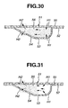
- the modified blister pack 51 shown in Figs. 28 - 31 is characterized by a sloped surface 54, as viewed from the cross section shown in Fig. 29.
- the blister pack 51 is comprised of base panel 52, sloped surface 54, lid panel 55, and medical powder storage chamber 56.
- the blistered portion 53 of blister pack 51 is formed with the previously-noted sloped surface 54 such that a side of the outflow holes (H2, H2) penetrating the radially-outward half of the blistered portion of base panel 52 is formed as a shallow portion, whereas a side of the inflow holes (H1, H1) penetrating the radially-inward half of the blistered portion of base panel 52 is formed as a deep portion.
- the base panel 52 has a plurality of blistered portions 53, 53, ..., 53 (eight blistered portions) around its entire circumference.
- the shape and material of the lid panel 55 of blister pack 51 are identical to those of blister pack 16 applied to the inhalant medicator of the first embodiment (or to those of blister pack 31 shown in Figs. 20 - 23).
- the modified blister pack 51 shown in Figs. 28 - 31 is different from the blister pack 21 shown in Figs. 15 - 17, in that the shape of each blistered portion 53 of base panel 52 differs from the shape of each blistered portion 23 of base panel 22.
- the blistered portions 53 are formed as eight radially-elongated, substantially elliptical convex portions.
- the radially-elongated outward half of the blistered portion 53 is formed as a comparatively shallow, sloped surface portion 54 (simply, a sloped surface), while the radially-elongated inward half of the blistered portion 53 is formed as a comparatively deep, recessed portion (simply, a deep recess), as viewed from the cross section shown in Fig. 29.
- the sloped surface 54 is dimensioned or sloped upwards (viewing Fig. 25) so that the convexity ratio of the blistered portion 53 radially decreases from the inside to the outside.
- the outflow holes (H2, H2) are pricked in the sloped surface 54, while the inflow holes (H1, H1) are pricked in the deep recess.
- the medical powder storage chamber 56 is defined between the blistered portion 53 of base panel 52 and the lid panel 55. A predetermined amount of medical powder is stored in the medical powder storage chamber 56, such that almost all of the medical powder is mainly stored in the deep recess corresponding to the inflow holes (H1, H1) by way of the sloped surface 54.
- the blister pack 51 shown in Figs. 28 - 31 is constructed as previously discussed. Hereinbelow described in detail in reference to Figs. 30 and 31 are the flow of air passing through the medical powder storage chamber 56 and the flow of medical powder within the storage chamber 56 during inhalation.
- Inflow holes (H1, H1) and outflow holes (H2, H2) are pricked in the blistered portion 53 of base panel 52 and in the lid panel 54 of blister pack 51 held at the predetermined pricking position, after a series of preliminary setting operations have been completed.
- air introduced through the inflow holes (H1, H1) into the storage chamber 56 is brought into direct-collision with the medical powder pre-stored in the deep recess of blistered portion 53 in which the inflow holes (H1, H1) are pricked.
- the medical powder is diffused within the storage chamber 56 at a breath (see Fig.
- the blister pack 51 having the sloped surface 54 at the outflow side thereof, it is possible to effectively diffuse the medical powder stored in the storage chamber by way of direct collision between the air flow introduced through the inflow holes (H1, H1) into the storage chamber and the medical powder stored.
- the blister pack 51 functions to uniformly disperse the medical powder into the entire air flow, while adequately diffusing the medical powder within the storage chamber 56. That is, the blister pack 51 permits medical powder to be stably supplied or inhaled into the lungs of the patient little by little.
- the modified blister pack 61 is characterized by a flow-constriction orifice passage 66 and a flap valve 67.
- the flow-constriction passage 66 is located between the radially inward and outward halves of the blistered portion 63 of the blister pack 61.
- the flap valve 67 is disposed in the flow-constriction passage 66 so that the flap valve fully opens only in presence of a strong inhaling action.
- the blister pack 61 is comprised of base panel 62, lid panel 64, medical powder storage chamber 65, flow-constriction passage 66, and flap valve 67.
- the base panel 62 has a thin-walled disc shape and is made of synthetic resin, aluminum material, or the like.
- the base panel 62 has a plurality of blistered portions 63, 63, ..., 63 (eight blistered portions) around its entire circumference.
- Each of the blistered portions 63 includes a radially-inward convex portion 63A and a radially-outward convex portion 63B, and a flow-constriction portion 63C provided between the two convex portions 63A and 63B.
- the shape and material of the lid panel 64 of blister pack 61 are identical to those of blister pack 21 applied to the inhalant medicator of the second embodiment.
- the lid panel 64 is formed at its inner wall with the flap valve 67 which opens and closes the flow-constriction passage 66.
- the lid panel 64 By hermetically covering the base panel 62 by the lid panel 64, eight medical powder storage chambers 65 are defined between the eight blistered portions 63 of base panel 62 and the lid panel 64. A predetermined amount of medical powder is stored in only the inward convex portion 63A of the two convex portions 63A and 63B of each of the blistered portions, before inhaling action is started.
- the blister pack 61 shown in Fig. 32 is different from the blister pack shown in Fig.
- the flap valve 67 is opened to permit fluid-communication between the two convex portions 63A and 63B, as indicated by the two-dotted line in Fig. 32.
- the blister pack 61 having the flap valve 67 disposed in the flow-constriction passage 66, it is possible to inhibit medical powder from being prescribed toward within lungs of the patient in case of a weak inhalation force.
- the blister pack 61 is designed to permit medical powder to be prescribed toward within the lungs of the patient, only when a level of the inhalation force exceeds a predetermined threshold value, and thus an acceptable inhalation-force level that adequately diffuses the medical powder is satisfied. Furthermore, it is possible to intermittently or pulsatively prescribe medical powder toward within lungs of a patient by adjusting the magnitude of the inhalation force. As discussed above, the blister pack 61 shown in Fig. 32 insures adequate diffusion of the medical powder, thus enhancing an efficiency of medication.
- each of the blistered portions 23 of blister pack 21 is formed as a radially-elongated, elliptical convex portion having the flow-constriction portion narrowed in a direction perpendicular to a flat surface of the lid panel.
- a blistered portion may be formed as a radially-extending, guitar-shaped or gourd-shaped convex portion 23' having a narrow part narrowed at its center in a transverse direction.
- the narrow portion of the gourd-shaped convex portion 23' forms a greatly reduced flow-constriction passage between the two convex portions 23A and 23B, thereby remarkably effectively increasing the flow velocity of air flow through the orifice passage 26.
Claims (5)
- Eine Inhalationsmedikamentenverabreichungsvorrichtung (1), die folgende Merkmale aufweist:einen Medikamentenverabreichungsvorrichtungskörper (2), der einen Halterbefestigungsabschnitt (6) an einem Axialende und ein Inhalationstor (7) an dem anderen Axialende zur Inhalation eines Medizinpulvers umfasst;einen Halter (8), der lösbar drehbar an dem Halterbefestigungsabschnitt (6) befestigt ist und an demselben einen Blasenblock (16) hält, der eine Basisplatte (16A) mit einer Mehrzahl blasiger Abschnitte (16B) und eine Deckelplatte (16C) aufweist, die an einer Vorderseite der Basisplatte (16A) befestigt ist und die blasigen Abschnitte (16B) der Basisplatte (16A) hermetisch bedeckt, um eine Mehrzahl von Medizinpulverspeicherkammern (16D) zu definieren, die voneinander in einer Umfangsrichtung derselben beabstandet sind;ein Stechwerkzeug (12), das an dem Medikamentenverabreichungsvorrichtungskörper (2) angebracht ist und zwei Stifte (14) aufweist; gekennzeichnet dadurch, dassder Medikamentenverabreichungsvorrichtungskörper (2) einen Abschnitt aufweist, der zwei Einströmluftdurchlässe (10) definiert, um Atmosphäre in Richtung einer der Mehrzahl von Medizinpulverspeicherkammern (16D) des Blasenblocks (16) zu liefern, der an dem Halter (8) gehalten wird, der an dem Halterbefestigungsabschnitt (6) befestigt ist;der Medikamentenverabreichungsvorrichtungskörper (2) einen Abschnitt aufweist, der zwei Ausströmluftdurchlässe (11) definiert, um das Medizinpulver, das in der einen Medizinpulverspeicherkammer (16D) des Blasenblocks (16) gespeichert ist, der an dem Halter (8) gehalten wird, in Richtung des Inhalationstors (7) ausströmen zu lassen; unddas Stechwerkzeug (12) angepasst ist, um gleichzeitig ein oberes Einström- und Ausströmloch (H1, H2) in der Deckeltafel (16C) zu durchstechen und gleichzeitig ein unteres Einström- und Ausströmloch (H1, H2) in dem einen blasigen Abschnitt (16B) des Blasenblocks (16) zu durchstechen, so dass das obere und das untere Einströmloch (H1, H1) fluidisch mit den jeweiligen Einströmluftdurchlässen (10) kommunizieren und das obere und das untere Ausströmloch (H2, H2) fluidisch mit den jeweiligen Ausströmluftdurchlässen (12) kommunizieren;wobei das obere Einström- und Ausströmloch (H1, H2) voneinander um eine vorbestimmte Entfernung beabstandet sind, die einer Entfernung zwischen einem stromabwärtigen Ende des ersten Einströmluftdurchlasses (10) und einem stromaufwärtigen Ende des ersten Ausströmluftdurchlasses (11) entspricht, und
wobei das untere Einström- und Ausströmloch (H1, H2) voneinander um eine vorbestimmte Entfernung beabstandet sind, die einer Entfernung zwischen einem stromabwärtigen Ende des zweiten Einströmluftdurchlasses (10) und einem stromaufwärtigen Ende des zweiten Ausströmluftdurchlasses (11) entspricht. - Die Inhalationsmedikamentenverabreichungsvorrichtung gemäß Anspruch 1, dadurch gekennzeichnet, dass
der Medikamentenverabreichungsvorrichtungskörper (2) einen oberen und einen unteren Medikamentenverabreichungsvorrichtungskörperabschnitt (4, 5) und einen Verbindungsabschnitt (3), durch den der obere und der untere Medikamentenverabreichungsvorrichtungskörperabschnitt (4, 5) einstückig miteinander gebildet sind, aufweist, wobei der obere und der untere Medikamentenverabreichungsvorrichtungskörperabschnitt (4, 5) zwischen sich eine Halterbefestigungsrille (6) definieren, die sich in drei Richtungen öffnet, die eine Links- und eine Rechts-Richtung, die senkrecht zu einer Achse des Medikamentenverabreichungsvorrichtungskörpers (2) sind, und eine Axialrichtung des Medikamentenverabreichungsvorrichtungskörpers (2) sind, wobei der Halter (8) einen plattenförmigen Halter aufweist, so dass der plattenförmige Halter in die Halterbefestigungsrille (6) eingeführt und aus derselben entfernt wird. - Die Inhalationsmedikamentenverabreichungsvorrichtung gemäß Anspruch 2, dadurch gekennzeichnet, dass
der Medikamentenverabreichungsvorrichtungskörper (2) einen vorstehenden Abschnitt (6D) aufweist, der an dem unteren Medikamentenverabreichungsvorrichtungskörperabschnitt (5) gebildet ist, der ein Rotationszentrum des Halters (8) ist, und der Halter (8) eine Mehrzahl ausgenommener Einpassabschnitte (8A) aufweist, die jeweils an einer Oberseite des Halters (8) gebildet sind und an eine der Mehrzahl von Medizinpulverspeicherkammern (16D) des Blasenblocks (16) eingepasst sind, und der Halter (8) einen Abschnitt aufweist, der eine Führungsrille (8E) definiert, die an einer Unterseite des Halters (8) gebildet ist, um den vorstehenden Abschnitt (6D) zu dem Rotationszentrum des Halters (8) zu führen. - Die Inhalationsmedikamentenverabreichungsvorrichtung gemäß Anspruch 3, gekennzeichnet durch
einen Positionierungsmechanismus (9), der zwischen dem Halterbefestigungsabschnitt des Medikamentenverabreichungsvorrichtungskörpers (2) und dem Halter (8) vorgesehen ist, zum Positionieren der einen Medizinpulverspeicherkammer (16D) des Blasenblocks (16), der an dem Halter (8) gehalten wird, in einer vorbestimmten Stechposition des Stechwerkzeugs (12). - Die Inhalationsmedikamentenverabreichungsvorrichtung gemäß Anspruch 4, bei der der Positionierungsmechanismus (9) ein Paar federbelasteter Kugeln (9B), die jeweils in einer eines Paars von Bohrungen (9A) gehäust sind, die jeweils an einem Ende geschlossen sind und in dem unteren Medikamentenverabreichungsvorrichtungskörperabschnitt (5) gebildet sind, und ein Paar von Federn (9C), die jeweils wirksam in einer der Bohrungen (9A) angeordnet sind, um so die Kugeln (9B) in einer Richtung vorzuspannen, die bewirkt, dass ein Teil einer sphärischen Oberfläche jeder der Kugeln (9D) durch ein Öffnungsende jeder der Bohrungen (9A) in die Halterbefestigungsrille (6) vorsteht, aufweist.
Applications Claiming Priority (5)
| Application Number | Priority Date | Filing Date | Title |
|---|---|---|---|
| JP35228099A JP3828698B2 (ja) | 1999-12-10 | 1999-12-10 | ブリスタパック |
| JP35228199 | 1999-12-10 | ||
| JP35228099 | 1999-12-10 | ||
| JP35228199A JP3685671B2 (ja) | 1999-12-10 | 1999-12-10 | 吸入式投薬器 |
| EP00125814A EP1106196B1 (de) | 1999-12-10 | 2000-11-24 | Blisterpackung für einen Inhalationsapparat |
Related Parent Applications (1)
| Application Number | Title | Priority Date | Filing Date |
|---|---|---|---|
| EP00125814A Division EP1106196B1 (de) | 1999-12-10 | 2000-11-24 | Blisterpackung für einen Inhalationsapparat |
Publications (5)
| Publication Number | Publication Date |
|---|---|
| EP1475115A2 EP1475115A2 (de) | 2004-11-10 |
| EP1475115A3 EP1475115A3 (de) | 2004-11-17 |
| EP1475115A8 EP1475115A8 (de) | 2005-01-12 |
| EP1475115A9 EP1475115A9 (de) | 2005-03-16 |
| EP1475115B1 true EP1475115B1 (de) | 2007-08-08 |
Family
ID=26579598
Family Applications (4)
| Application Number | Title | Priority Date | Filing Date |
|---|---|---|---|
| EP04018486A Expired - Lifetime EP1475115B1 (de) | 1999-12-10 | 2000-11-24 | Trockenpulverinhalator |
| EP05022452A Withdrawn EP1618911A3 (de) | 1999-12-10 | 2000-11-24 | Blisterpackung für einen Inhalationsapparat |
| EP00125814A Expired - Lifetime EP1106196B1 (de) | 1999-12-10 | 2000-11-24 | Blisterpackung für einen Inhalationsapparat |
| EP05022451A Withdrawn EP1618910A3 (de) | 1999-12-10 | 2000-11-24 | Blisterpackung für einen Inhalationsapparat |
Family Applications After (3)
| Application Number | Title | Priority Date | Filing Date |
|---|---|---|---|
| EP05022452A Withdrawn EP1618911A3 (de) | 1999-12-10 | 2000-11-24 | Blisterpackung für einen Inhalationsapparat |
| EP00125814A Expired - Lifetime EP1106196B1 (de) | 1999-12-10 | 2000-11-24 | Blisterpackung für einen Inhalationsapparat |
| EP05022451A Withdrawn EP1618910A3 (de) | 1999-12-10 | 2000-11-24 | Blisterpackung für einen Inhalationsapparat |
Country Status (4)
| Country | Link |
|---|---|
| US (2) | US6810872B1 (de) |
| EP (4) | EP1475115B1 (de) |
| DE (2) | DE60035911T2 (de) |
| PT (2) | PT1475115E (de) |
Families Citing this family (111)
| Publication number | Priority date | Publication date | Assignee | Title |
|---|---|---|---|---|
| GB2353222B (en) | 1999-06-23 | 2001-09-19 | Cambridge Consultants | Inhalers |
| GB9920839D0 (en) | 1999-09-04 | 1999-11-10 | Innovata Biomed Ltd | Inhaler |
| US6679256B2 (en) † | 1999-12-17 | 2004-01-20 | Nektar Therapeutics | Systems and methods for extracting powders from receptacles |
| US6971383B2 (en) | 2001-01-24 | 2005-12-06 | University Of North Carolina At Chapel Hill | Dry powder inhaler devices, multi-dose dry powder drug packages, control systems, and associated methods |
| FI20011317A0 (fi) * | 2001-06-20 | 2001-06-20 | Orion Corp | Jauheinhalaattori |
| WO2003026559A2 (en) | 2001-09-28 | 2003-04-03 | Kurve Technology, Inc | Nasal nebulizer |
| GB2380410B (en) * | 2001-10-05 | 2003-11-19 | Alchemy Healthcare Ltd | Apparatus for the nasal or oral delivery of a medicament |
| GB0128148D0 (en) | 2001-11-23 | 2002-01-16 | Innovata Biomed Ltd | Assembly |
| US20030235538A1 (en) * | 2002-04-09 | 2003-12-25 | Boehringer Ingelheim Pharma Gmbh & Co. Kg | Method for the administration of an anticholinergic by inhalation |
| AU2003249623A1 (en) * | 2002-05-09 | 2003-12-12 | Kurve Technology, Inc. | Particle dispersion chamber for nasal nebulizer |
| US7677411B2 (en) | 2002-05-10 | 2010-03-16 | Oriel Therapeutics, Inc. | Apparatus, systems and related methods for processing, dispensing and/or evaluatingl dry powders |
| JP2005532091A (ja) * | 2002-05-10 | 2005-10-27 | オリエル・セラピューティクス,インコーポレイテッド | ドライ・パウダー吸入器、関連するブリスター装置、およびドライ・パウダー物質を施与しならびにブリスター・パッケージを製作する関連付けられた方法 |
| US6889690B2 (en) | 2002-05-10 | 2005-05-10 | Oriel Therapeutics, Inc. | Dry powder inhalers, related blister devices, and associated methods of dispensing dry powder substances and fabricating blister packages |
| WO2004045487A2 (en) * | 2002-11-20 | 2004-06-03 | Sun Pharmaceutical Industries Limited | Dry powder inhaler |
| US7284553B2 (en) * | 2002-12-12 | 2007-10-23 | Boehringer Ingelheim Pharma Gmbh & Co. Kg | Powder inhaler comprising a chamber for a capsule for taking up a non-returnable capsule being filled with an active ingredient |
| AR042452A1 (es) * | 2002-12-13 | 2005-06-22 | Otsuka Pharma Co Ltd | Dispositivo de inhalacion para la administrcion transpulmonar |
| GB0312007D0 (en) * | 2003-05-24 | 2003-07-02 | Innovata Biomed Ltd | Container |
| GB0315509D0 (en) * | 2003-07-02 | 2003-08-06 | Meridica Ltd | Dispensing device |
| US20070131230A1 (en) * | 2003-09-05 | 2007-06-14 | Kurve Technology, Inc. | Nasal adapter for the base of the nose |
| EP1673123A2 (de) * | 2003-09-05 | 2006-06-28 | Kurve Technology, Inc. | Integrierter vernebler und teilchendispersionskammer zur abgabe eines medikaments |
| GB2405798A (en) * | 2003-09-15 | 2005-03-16 | Vectura Ltd | Dry powder inhaler with primary and secondary piercing elements and a medicament pack for use with an inhalation device. |
| WO2005041848A2 (en) * | 2003-10-27 | 2005-05-12 | Oriel Therapeutics, Inc. | Dry powder drug containment system packages with tabs, inhalers and associated methods |
| JP2007533387A (ja) | 2004-04-21 | 2007-11-22 | イノベータ バイオメド リミテッド | 吸入器 |
| US7861712B2 (en) * | 2004-04-23 | 2011-01-04 | Manta Product Development | Sealed capsule including an integrated puncturing mechanism |
| JP2007534384A (ja) * | 2004-04-23 | 2007-11-29 | ミスティック ファーマシューティカルズ, インコーポレイテッド | 複数の単位用量の薬物送達システム |
| GB0409197D0 (en) | 2004-04-24 | 2004-05-26 | Innovata Biomed Ltd | Device |
| WO2005110519A1 (en) * | 2004-05-17 | 2005-11-24 | Sun Pharmaceutical Industries Limited | Dry powder inhaler |
| EP1778322B1 (de) * | 2004-07-26 | 2017-11-22 | 1355540 Ontario Inc. | Pulverinhalator mit verringertem kompaktionsinhalator |
| CA2616997C (en) | 2004-09-13 | 2014-12-23 | Oriel Therapeutics, Inc. | Dry powder inhalers that inhibit agglomeration, related devices and methods |
| JP2006130143A (ja) * | 2004-11-08 | 2006-05-25 | Hitachi Ltd | 吸入式投薬器及び薬剤カートリッジ |
| FR2877925B1 (fr) * | 2004-11-16 | 2008-09-19 | Valois Sas | Dispositif de distribution de produit fluide. |
| GB0427028D0 (en) * | 2004-12-09 | 2005-01-12 | Cambridge Consultants | Dry powder inhalers |
| GB0427853D0 (en) * | 2004-12-20 | 2005-01-19 | Glaxo Group Ltd | Manifold for use in medicament dispenser |
| US20070012316A1 (en) * | 2005-07-14 | 2007-01-18 | Joann Truza | Disposable compact rescue inhaler |
| US8763605B2 (en) | 2005-07-20 | 2014-07-01 | Manta Devices, Llc | Inhalation device |
| DE102006014434A1 (de) * | 2006-03-27 | 2007-10-04 | Boehringer Ingelheim Pharma Gmbh & Co. Kg | Packmittel für Mehrdosispulverinhalatoren mit optimierten Entleerungseigenschaften |
| DE102006016904A1 (de) * | 2006-04-11 | 2007-10-25 | Boehringer Ingelheim Pharma Gmbh & Co. Kg | Inhalator |
| DE102006016901A1 (de) * | 2006-04-11 | 2007-10-25 | Boehringer Ingelheim Pharma Gmbh & Co. Kg | Mundstück für einen Inhalator |
| EP1844806A1 (de) * | 2006-04-13 | 2007-10-17 | Boehringer Ingelheim Pharma GmbH | Medikamenten-Ausgabevorrichtung, Medikamentenmagazin dafür, und Verfahren zur Entnahme eines Medikaments aus einer Medikamentenkammer |
| PT103481B (pt) * | 2006-05-16 | 2008-08-01 | Hovione Farmaciencia S A | Inalador de uso simples e método de inalação |
| US7806117B2 (en) * | 2006-06-07 | 2010-10-05 | Shin Nippon Biomedical Laboratories, Ltd. | Peroral powder delivery device |
| JP2009539531A (ja) * | 2006-06-16 | 2009-11-19 | シプラ・リミテッド | 改良型乾燥粉末吸入装置 |
| EP2043717A1 (de) * | 2006-07-14 | 2009-04-08 | Astra Zeneca AB | Inhaliersystem und abgabevorrichtung zur verabreichung eines arzneimittels in form eines trockenpulvers |
| WO2008028092A2 (en) | 2006-08-30 | 2008-03-06 | Kurve Technology, Inc. | Aerosol generating and delivery device |
| DE102006045788A1 (de) * | 2006-09-26 | 2008-03-27 | Alfred Von Schuckmann | Spender für pulverförmige Massen |
| GB0621957D0 (en) * | 2006-11-03 | 2006-12-13 | Vectura Group Plc | Inhaler devices and bespoke pharmaceutical compositions |
| WO2008086413A2 (en) * | 2007-01-09 | 2008-07-17 | Mystic Pharmaceuticals, Inc. | Intranasal cartridge devices |
| GB0700839D0 (en) * | 2007-01-17 | 2007-02-21 | Braithwaite Philip | Device |
| US8616199B2 (en) * | 2007-03-16 | 2013-12-31 | Canon Kabushiki Kaisha | Inhaler and ejection head unit attachable to the inhaler |
| US8683995B2 (en) | 2007-05-16 | 2014-04-01 | Mystic Pharmaceuticals, Inc. | Dose dispensing containers |
| US9248076B2 (en) | 2007-05-16 | 2016-02-02 | Mystic Pharmaceuticals, Inc. | Dose dispensing containers |
| CN105776119B (zh) | 2007-05-16 | 2019-04-23 | 神秘制药公司 | 组成物单位剂量分配容器 |
| WO2009004456A1 (en) * | 2007-07-02 | 2009-01-08 | Pfizer Limited | Dry powder container and use of such dry powder container in a dry powder inhaler |
| EP2170444B1 (de) | 2007-07-06 | 2016-09-07 | Manta Devices, LLC | Inhalationsvorrichtungen zur lagerung und abgabe von medikamenten |
| US11224704B2 (en) | 2007-07-06 | 2022-01-18 | Manta Devices, Llc | Dose delivery device for inhalation |
| CA2886525A1 (en) * | 2007-09-14 | 2009-03-19 | Mystic Pharmaceuticals, Inc. | Deep draw container forming method |
| EP2224984A4 (de) | 2007-12-20 | 2013-10-30 | Astrazeneca Ab | Spender und verfahren zur einspeisung von pulver in einen luftstrom |
| EP2082763A1 (de) * | 2008-01-24 | 2009-07-29 | Boehringer Ingelheim International Gmbh | Inhalator |
| GB0802030D0 (en) * | 2008-02-05 | 2008-03-12 | Dunne Stephen T | Blister piercer |
| EP3272379A1 (de) | 2008-02-07 | 2018-01-24 | The University of Washington | Ringförmige aerosolvorrichtung |
| BRPI0919126B1 (pt) | 2008-09-26 | 2021-07-27 | Oriel Therapeutics, Inc | Inalador de pó seco |
| KR101311977B1 (ko) | 2008-09-26 | 2013-09-26 | 오리엘 테라퓨틱스, 인크. | 분리된 공기통로 채널들을 갖는 공기통로 디스크들 및 관련된 디스크들을 구비한 흡입기 및 이와 관련된 방법 |
| US8887722B2 (en) * | 2008-09-26 | 2014-11-18 | Oriel Therapeutics, Inc. | Inhaler mechanisms with radially biased piercers and related methods |
| US9050427B2 (en) * | 2008-09-30 | 2015-06-09 | Oriel Therapeutics, Inc. | Dry powder inhalers with multi-facet surface deagglomeration chambers and related devices and methods |
| MX2011003245A (es) * | 2008-10-01 | 2011-04-26 | Oriel Therapeutics Inc | Inhaladores de polvo seco con mecanismos de perforacion giratorios y dispositivos y metodos relacionados. |
| EP2198907A1 (de) * | 2008-12-19 | 2010-06-23 | Boehringer Ingelheim International GmbH | Inhalator |
| US8550074B2 (en) | 2009-01-15 | 2013-10-08 | Manta Devices, Llc | Delivery device and related methods |
| NZ597009A (en) | 2009-07-01 | 2014-05-30 | Astrazeneca Ab | Dispenser and method for entraining powder in an airflow |
| US9492625B2 (en) | 2009-11-12 | 2016-11-15 | Stc.Unm | Dry powder inhaler with flutter dispersion member |
| KR20120115264A (ko) * | 2009-11-13 | 2012-10-17 | 머크 샤프 앤드 돔 코포레이션 | 다수의 저장부를 가지는 투약 제품 및 건식 분말 흡입기 |
| EP2498846A4 (de) * | 2009-11-13 | 2014-08-27 | Merck Sharp & Dohme | Arzneimittelprodukte, trockenpulverinhalatoren und mehrfachfluss-kollisionsanordnungen |
| WO2011116293A2 (en) | 2010-03-19 | 2011-09-22 | Manta Devices, Llc | Delivery device and related methods |
| USD635246S1 (en) | 2010-03-26 | 2011-03-29 | Oriel Therapeutics, Inc. | Dose disk for dry powder inhalers |
| USD641076S1 (en) | 2010-03-26 | 2011-07-05 | Oriel Therapeutics, Inc. | Dry powder inhaler |
| RU2013104024A (ru) | 2010-07-21 | 2014-08-27 | Астразенека Аб | Ингалятор |
| EP2648788B1 (de) | 2010-12-07 | 2017-08-09 | Respira Therapeutics, Inc. | Trockenpulverinhalator |
| RU2612506C2 (ru) | 2011-03-03 | 2017-03-09 | Импел Ньюрофарма Инк. | Устройство для назальной доставки лекарственных средств |
| CA2835208C (en) | 2011-05-09 | 2019-08-20 | Impel Neuropharma, Inc. | Nozzles for nasal drug delivery |
| PL2709700T3 (pl) * | 2011-05-16 | 2017-01-31 | The Technology Partnership Plc | Pojemnik dawki |
| US11103659B2 (en) | 2011-07-06 | 2021-08-31 | Manta Devices, Llc | Delivery device and related methods |
| CA2846899C (en) | 2011-09-07 | 2019-12-03 | Syphase, Llc | Dry powder inhalation device |
| US10463815B2 (en) | 2012-02-21 | 2019-11-05 | Respira Therapeutics, Inc. | Inhaler to deliver substances for prophylaxis or prevention of disease or injury caused by the inhalation of biological or chemical agents |
| US9649454B2 (en) | 2012-05-03 | 2017-05-16 | Manta Devices, Llc | Delivery device and related methods |
| AU2013202919C1 (en) * | 2012-07-03 | 2016-02-04 | Advent Pharmaceuticals Pty Ltd | Blister Pack |
| EP2914320B1 (de) * | 2012-10-31 | 2019-12-04 | Inhaletech LLC | Systeme zur medikamentösen behandlung der lunge |
| US10537692B2 (en) | 2013-04-28 | 2020-01-21 | Impel Neuropharma, Inc. | Medical unit dose container |
| SE537715C2 (sv) * | 2013-11-26 | 2015-10-06 | Simplified Solutions Sweden Ab | Inhalationsanordning för ämnen i pulverform |
| US11147936B2 (en) | 2014-05-02 | 2021-10-19 | Manta Devices, Llc | Dose delivery device with cover connected to dose chamber seal |
| AU2015352888C1 (en) * | 2014-11-26 | 2018-02-15 | Vectura Delivery Devices Limited | Dry powder inhaler |
| EP3838317A1 (de) | 2015-01-14 | 2021-06-23 | Respira Therapeutics, Inc. | Trockenpulverinhalator |
| PT108426B (pt) | 2015-04-30 | 2017-07-24 | Hovione Farmaciência S A | Inalador de pó para administração de doses elevadas de fármacos |
| IL257845B (en) | 2015-09-10 | 2022-07-01 | Impel Neuropharma Inc | Lined nasal delivery device |
| WO2017144386A1 (de) * | 2016-02-24 | 2017-08-31 | Boehringer Ingelheim International Gmbh | Inhalator |
| DE102016119789A1 (de) * | 2016-07-04 | 2018-01-04 | Alfred Von Schuckmann | Vorrichtung zur Ausgabe einer durch Luft austragbaren Substanz |
| GB201615602D0 (en) * | 2016-09-14 | 2016-10-26 | British American Tobacco Investments Ltd | Receptacle Section |
| GB201615601D0 (en) | 2016-09-14 | 2016-10-26 | British American Tobacco Investments Ltd | Receptacle section |
| CA3039908A1 (en) * | 2016-10-11 | 2018-04-19 | Microdose Therapeutx, Inc. | Inhaler and methods of use thereof |
| GB201700136D0 (en) | 2017-01-05 | 2017-02-22 | British American Tobacco Investments Ltd | Aerosol generating device and article |
| GB201700620D0 (en) | 2017-01-13 | 2017-03-01 | British American Tobacco Investments Ltd | Aerosol generating device and article |
| CN107080885B (zh) * | 2017-02-21 | 2020-09-25 | 鑑道生命科技有限公司 | 一种定量释放香气的肺功能改善装置 |
| BR112019019107A2 (pt) * | 2017-03-15 | 2020-04-22 | Csp Technologies Inc | inalador e métodos de uso e produção do mesmo |
| AU2018244582A1 (en) | 2017-03-28 | 2019-09-19 | Concentrx Pharmaceuticals, Inc. | Devices and methods for delivering dry powder medicaments |
| EP3713626A4 (de) | 2017-11-21 | 2021-08-18 | Impel Neuropharma Inc. | Intranasale vorrichtung mit einlassschnittstelle |
| EP3713628A4 (de) | 2017-11-21 | 2021-08-18 | Impel Neuropharma Inc. | Intranasale vorrichtung mit tauchrohr |
| GB201720338D0 (en) | 2017-12-06 | 2018-01-17 | British American Tobacco Investments Ltd | Component for an aerosol-generating apparatus |
| JP2021509677A (ja) | 2018-01-05 | 2021-04-01 | インペル ニューロファーマ インコーポレイテッド | 精密嗅覚装置によるオランザピンの鼻孔間送達 |
| BR112020013744A8 (pt) | 2018-01-05 | 2022-10-18 | Impel Neuropharma Inc | Dispensação intranasal de di-hidroergotamina por dispositivo olfativo de precisão |
| WO2020018959A1 (en) | 2018-07-19 | 2020-01-23 | Impel Neuropharma, Inc. | Respiratory tract delivery of levodopa and dopa decarboxylase inhibitor for treatment of parkinson's disease |
| AU2019418744B2 (en) | 2019-01-03 | 2023-08-03 | Impel Pharmaceuticals Inc. | Nasal drug delivery device |
| JP2022532259A (ja) | 2019-05-17 | 2022-07-13 | インペル ファーマシューティカルズ インコーポレイテッド | 使い捨ての鼻腔内送達デバイス |
| EP4221793A1 (de) | 2021-09-29 | 2023-08-09 | Norton (Waterford) Limited | Inhalator für medikamente in form eines trockenpulvers |
Family Cites Families (32)
| Publication number | Priority date | Publication date | Assignee | Title |
|---|---|---|---|---|
| US3831606A (en) * | 1971-02-19 | 1974-08-27 | Alza Corp | Auto inhaler |
| US3967761A (en) * | 1974-04-08 | 1976-07-06 | Southwest Research Institute | System for injecting particulate material into the combustion chamber of a repetitive combustion coating apparatus |
| US3971377A (en) * | 1974-06-10 | 1976-07-27 | Alza Corporation | Medicament dispensing process for inhalation therapy |
| CH581992A5 (de) * | 1975-08-15 | 1976-11-30 | Laib Jakob C | |
| US4298125A (en) * | 1980-05-19 | 1981-11-03 | Bristol-Myers Company | Dial type child resistant dispenser |
| AU570013B2 (en) | 1982-10-08 | 1988-03-03 | Glaxo Group Limited | Medicament inhaler |
| US4778054A (en) * | 1982-10-08 | 1988-10-18 | Glaxo Group Limited | Pack for administering medicaments to patients |
| ZA837318B (en) | 1982-10-08 | 1985-06-26 | Glaxo Group Ltd | Device for administering medicaments to patients |
| GB2169265B (en) | 1982-10-08 | 1987-08-12 | Glaxo Group Ltd | Pack for medicament |
| AU591152B2 (en) | 1985-07-30 | 1989-11-30 | Glaxo Group Limited | Devices for administering medicaments to patients |
| US4691820A (en) * | 1985-11-18 | 1987-09-08 | Vistakon, Inc. | Package for hydrophilic contact lens |
| IT1228459B (it) * | 1989-02-23 | 1991-06-19 | Phidea S R L | Inalatore con svuotamento regolare e completo della capsula. |
| US5239991A (en) | 1989-06-21 | 1993-08-31 | Fisons Plc | Disposable powder medicament inhalation device with peel-off cover |
| DE3927170A1 (de) | 1989-08-17 | 1991-02-21 | Boehringer Ingelheim Kg | Inhalator |
| US5337740A (en) | 1991-08-01 | 1994-08-16 | New England Pharmaceuticals, Inc. | Inhalation devices |
| DE4128295A1 (de) | 1991-08-27 | 1993-03-04 | Pfeiffer Erich Gmbh & Co Kg | Austragvorrichtung fuer fliessfaehige medien |
| DE9204577U1 (de) * | 1992-04-03 | 1992-05-21 | Dr. Karl Thomae Gmbh, 7950 Biberach, De | |
| GB9303525D0 (en) * | 1993-02-22 | 1993-04-07 | Boots Co Plc | Medicament presentation |
| US5533502A (en) | 1993-05-28 | 1996-07-09 | Vortran Medical Technology, Inc. | Powder inhaler with aerosolization occurring within each individual powder receptacle |
| US5349947A (en) * | 1993-07-15 | 1994-09-27 | Newhouse Michael T | Dry powder inhaler and process that explosively discharges a dose of powder and gas from a soft plastic pillow |
| DE4400083C2 (de) * | 1994-01-04 | 1997-07-03 | Asta Medica Ag | Verpackung für kleine vordosierte Mengen eines fein verteilten Feststoffs |
| JP3372105B2 (ja) | 1994-05-26 | 2003-01-27 | 株式会社日立ユニシアオートモティブ | 吸入式投薬器 |
| US5483954A (en) * | 1994-06-10 | 1996-01-16 | Mecikalski; Mark B. | Inhaler and medicated package |
| US5622166A (en) * | 1995-04-24 | 1997-04-22 | Dura Pharmaceuticals, Inc. | Dry powder inhaler delivery system |
| DE19523516C1 (de) * | 1995-06-30 | 1996-10-31 | Asta Medica Ag | Inhalator zum Verabreichen von Medikamenten aus Blisterpackungen |
| US6209538B1 (en) | 1995-08-02 | 2001-04-03 | Robert A. Casper | Dry powder medicament inhalator having an inhalation-activated flow diverting means for triggering delivery of medicament |
| US5988163A (en) * | 1995-08-02 | 1999-11-23 | Innovative Devices | Dry powder medicament inhalator having an inhalation-activated flow diverting means for triggering delivery of delivery of medicament |
| US5669378A (en) * | 1995-12-21 | 1997-09-23 | Pera; Ivo | Inhaling device |
| CA2212430A1 (en) | 1997-08-07 | 1999-02-07 | George Volgyesi | Inhalation device |
| US5839609A (en) * | 1997-08-27 | 1998-11-24 | Colgate-Palmolive Company | Thermoformed pack with ridge valve |
| GB9810126D0 (de) * | 1998-05-13 | 1998-07-08 | Glaxo Group Ltd | |
| GB2340758A (en) | 1998-08-21 | 2000-03-01 | Bespak Plc | Drug dispensing system |
-
2000
- 2000-11-02 US US09/703,794 patent/US6810872B1/en not_active Expired - Fee Related
- 2000-11-24 PT PT04018486T patent/PT1475115E/pt unknown
- 2000-11-24 EP EP04018486A patent/EP1475115B1/de not_active Expired - Lifetime
- 2000-11-24 DE DE60035911T patent/DE60035911T2/de not_active Expired - Fee Related
- 2000-11-24 EP EP05022452A patent/EP1618911A3/de not_active Withdrawn
- 2000-11-24 DE DE60029727T patent/DE60029727T2/de not_active Expired - Fee Related
- 2000-11-24 PT PT00125814T patent/PT1106196E/pt unknown
- 2000-11-24 EP EP00125814A patent/EP1106196B1/de not_active Expired - Lifetime
- 2000-11-24 EP EP05022451A patent/EP1618910A3/de not_active Withdrawn
-
2004
- 2004-10-08 US US10/960,575 patent/US20050048003A1/en not_active Abandoned
Also Published As
| Publication number | Publication date |
|---|---|
| EP1618911A2 (de) | 2006-01-25 |
| US20050048003A1 (en) | 2005-03-03 |
| EP1106196A3 (de) | 2004-01-07 |
| EP1618911A3 (de) | 2006-05-31 |
| EP1475115A3 (de) | 2004-11-17 |
| PT1106196E (pt) | 2006-11-30 |
| EP1475115A8 (de) | 2005-01-12 |
| EP1106196A2 (de) | 2001-06-13 |
| DE60035911T2 (de) | 2008-04-17 |
| US6810872B1 (en) | 2004-11-02 |
| EP1475115A2 (de) | 2004-11-10 |
| EP1475115A9 (de) | 2005-03-16 |
| EP1618910A3 (de) | 2006-02-08 |
| EP1618910A2 (de) | 2006-01-25 |
| DE60029727D1 (de) | 2006-09-14 |
| DE60035911D1 (de) | 2007-09-20 |
| DE60029727T2 (de) | 2007-08-02 |
| EP1106196B1 (de) | 2006-08-02 |
| PT1475115E (pt) | 2007-09-24 |
Similar Documents
| Publication | Publication Date | Title |
|---|---|---|
| EP1475115B1 (de) | Trockenpulverinhalator | |
| US6408846B1 (en) | Inhalation type drug dispenser | |
| EP1068874B1 (de) | Medikamentenabgabevorrichtung in form eines inhalators | |
| EP0973571B1 (de) | Inhalationsapparat | |
| EP0796628B1 (de) | Inhalator | |
| RU2456026C2 (ru) | Усовершенствованный ингалятор для сухого порошкообразного препарата | |
| JP2912453B2 (ja) | 乾燥粉末の吸入器 | |
| EP0696458B1 (de) | Inhalationsgerät für medizinische Zwecke | |
| EP1731186B1 (de) | Vorrichtung zur Verabreichung von pulverförmigen Medikamenten | |
| US6341605B1 (en) | Inhalant medicator | |
| JP3328131B2 (ja) | 吸入式投薬器 | |
| JP3828698B2 (ja) | ブリスタパック | |
| JP3845530B2 (ja) | 吸入式投薬器 | |
| JP3315031B2 (ja) | 投薬器 | |
| JP3685671B2 (ja) | 吸入式投薬器 | |
| JPH11299891A (ja) | 吸入式投薬器 | |
| JP2006142102A (ja) | ブリスタパック | |
| JP3547612B2 (ja) | 吸入式投薬器 | |
| JPH09253209A (ja) | 吸入式投薬器 | |
| JPH09140792A (ja) | 投薬器 | |
| JP2000217918A (ja) | 吸入式投薬器 | |
| JPH11267213A (ja) | 吸入式投薬器 | |
| JPH1128248A (ja) | 吸入式投薬器 |
Legal Events
| Date | Code | Title | Description |
|---|---|---|---|
| PUAI | Public reference made under article 153(3) epc to a published international application that has entered the european phase |
Free format text: ORIGINAL CODE: 0009012 |
|
| PUAL | Search report despatched |
Free format text: ORIGINAL CODE: 0009013 |
|
| 17P | Request for examination filed |
Effective date: 20040804 |
|
| AC | Divisional application: reference to earlier application |
Ref document number: 1106196 Country of ref document: EP Kind code of ref document: P |
|
| AK | Designated contracting states |
Kind code of ref document: A2 Designated state(s): CH DE FR GB LI PT |
|
| AK | Designated contracting states |
Kind code of ref document: A3 Designated state(s): CH DE FR GB LI PT |
|
| RIN1 | Information on inventor provided before grant (corrected) |
Inventor name: YAZAWA, YOSHIYUKI,UNISIA JECS CORPORATION Inventor name: OHKI, HISATOMO,UNISIA JECS CORPORATION Inventor name: YANAGAWA, AKIRA,DOTT LIMITED COMPANY Inventor name: NAKAMURA, SHIGEMI,UNISIA JECS CORPORATION Inventor name: ISHIZEKI, KAZUNORI,UNISIA JECS CORPORATION |
|
| RIN1 | Information on inventor provided before grant (corrected) |
Inventor name: OHKI, HISATOMO,UNISIA JECS CORPORATION Inventor name: NAKAMURA, SHIGEMI,UNISIA JECS CORPORATION Inventor name: YANAGAWA, AKIRA,DOTT LIMITED COMPANY Inventor name: YAZAWA, YOSHIYUKI,C/O UNISIA JECS CORPORATION Inventor name: ISHIZEKI, KAZUNORI,UNISIA JECS CORPORATION |
|
| RAP1 | Party data changed (applicant data changed or rights of an application transferred) |
Owner name: HITACHI, LTD. Owner name: DOTT LIMITED COMPANY |
|
| 17Q | First examination report despatched |
Effective date: 20050407 |
|
| AKX | Designation fees paid |
Designated state(s): CH DE FR GB LI PT |
|
| RTI1 | Title (correction) |
Free format text: DRY POWDER INHALER |
|
| GRAP | Despatch of communication of intention to grant a patent |
Free format text: ORIGINAL CODE: EPIDOSNIGR1 |
|
| GRAS | Grant fee paid |
Free format text: ORIGINAL CODE: EPIDOSNIGR3 |
|
| GRAA | (expected) grant |
Free format text: ORIGINAL CODE: 0009210 |
|
| AC | Divisional application: reference to earlier application |
Ref document number: 1106196 Country of ref document: EP Kind code of ref document: P |
|
| AK | Designated contracting states |
Kind code of ref document: B1 Designated state(s): CH DE FR GB LI PT |
|
| REG | Reference to a national code |
Ref country code: GB Ref legal event code: FG4D |
|
| REG | Reference to a national code |
Ref country code: CH Ref legal event code: EP |
|
| REF | Corresponds to: |
Ref document number: 60035911 Country of ref document: DE Date of ref document: 20070920 Kind code of ref document: P |
|
| REG | Reference to a national code |
Ref country code: PT Ref legal event code: SC4A Free format text: AVAILABILITY OF NATIONAL TRANSLATION Effective date: 20070911 |
|
| ET | Fr: translation filed | ||
| REG | Reference to a national code |
Ref country code: CH Ref legal event code: NV Representative=s name: BOVARD AG PATENTANWAELTE |
|
| PGFP | Annual fee paid to national office [announced via postgrant information from national office to epo] |
Ref country code: FR Payment date: 20071116 Year of fee payment: 8 |
|
| PGFP | Annual fee paid to national office [announced via postgrant information from national office to epo] |
Ref country code: PT Payment date: 20071018 Year of fee payment: 8 |
|
| PLBE | No opposition filed within time limit |
Free format text: ORIGINAL CODE: 0009261 |
|
| STAA | Information on the status of an ep patent application or granted ep patent |
Free format text: STATUS: NO OPPOSITION FILED WITHIN TIME LIMIT |
|
| 26N | No opposition filed |
Effective date: 20080509 |
|
| PGFP | Annual fee paid to national office [announced via postgrant information from national office to epo] |
Ref country code: CH Payment date: 20081130 Year of fee payment: 9 Ref country code: DE Payment date: 20081120 Year of fee payment: 9 |
|
| REG | Reference to a national code |
Ref country code: PT Ref legal event code: MM4A Free format text: LAPSE DUE TO NON-PAYMENT OF FEES Effective date: 20090525 |
|
| PGFP | Annual fee paid to national office [announced via postgrant information from national office to epo] |
Ref country code: GB Payment date: 20081119 Year of fee payment: 9 |
|
| PG25 | Lapsed in a contracting state [announced via postgrant information from national office to epo] |
Ref country code: PT Free format text: LAPSE BECAUSE OF NON-PAYMENT OF DUE FEES Effective date: 20090525 |
|
| REG | Reference to a national code |
Ref country code: FR Ref legal event code: ST Effective date: 20090731 |
|
| REG | Reference to a national code |
Ref country code: CH Ref legal event code: PL |
|
| GBPC | Gb: european patent ceased through non-payment of renewal fee |
Effective date: 20091124 |
|
| PG25 | Lapsed in a contracting state [announced via postgrant information from national office to epo] |
Ref country code: LI Free format text: LAPSE BECAUSE OF NON-PAYMENT OF DUE FEES Effective date: 20091130 Ref country code: CH Free format text: LAPSE BECAUSE OF NON-PAYMENT OF DUE FEES Effective date: 20091130 |
|
| PG25 | Lapsed in a contracting state [announced via postgrant information from national office to epo] |
Ref country code: DE Free format text: LAPSE BECAUSE OF NON-PAYMENT OF DUE FEES Effective date: 20100601 |
|
| PG25 | Lapsed in a contracting state [announced via postgrant information from national office to epo] |
Ref country code: GB Free format text: LAPSE BECAUSE OF NON-PAYMENT OF DUE FEES Effective date: 20091124 |
|
| PG25 | Lapsed in a contracting state [announced via postgrant information from national office to epo] |
Ref country code: FR Free format text: LAPSE BECAUSE OF NON-PAYMENT OF DUE FEES Effective date: 20081130 |