EP1472579B1 - Système robotique avec centre de mouvement à distance - Google Patents
Système robotique avec centre de mouvement à distance Download PDFInfo
- Publication number
- EP1472579B1 EP1472579B1 EP03710669.7A EP03710669A EP1472579B1 EP 1472579 B1 EP1472579 B1 EP 1472579B1 EP 03710669 A EP03710669 A EP 03710669A EP 1472579 B1 EP1472579 B1 EP 1472579B1
- Authority
- EP
- European Patent Office
- Prior art keywords
- coupled
- effector
- rcm
- linking
- axis
- Prior art date
- Legal status (The legal status is an assumption and is not a legal conclusion. Google has not performed a legal analysis and makes no representation as to the accuracy of the status listed.)
- Expired - Lifetime
Links
Images


Classifications
-
- B—PERFORMING OPERATIONS; TRANSPORTING
- B25—HAND TOOLS; PORTABLE POWER-DRIVEN TOOLS; MANIPULATORS
- B25J—MANIPULATORS; CHAMBERS PROVIDED WITH MANIPULATION DEVICES
- B25J18/00—Arms
- B25J18/007—Arms the end effector rotating around a fixed point
-
- A—HUMAN NECESSITIES
- A61—MEDICAL OR VETERINARY SCIENCE; HYGIENE
- A61B—DIAGNOSIS; SURGERY; IDENTIFICATION
- A61B34/00—Computer-aided surgery; Manipulators or robots specially adapted for use in surgery
- A61B34/30—Surgical robots
-
- A—HUMAN NECESSITIES
- A61—MEDICAL OR VETERINARY SCIENCE; HYGIENE
- A61B—DIAGNOSIS; SURGERY; IDENTIFICATION
- A61B34/00—Computer-aided surgery; Manipulators or robots specially adapted for use in surgery
- A61B34/70—Manipulators specially adapted for use in surgery
- A61B34/71—Manipulators operated by drive cable mechanisms
-
- B—PERFORMING OPERATIONS; TRANSPORTING
- B25—HAND TOOLS; PORTABLE POWER-DRIVEN TOOLS; MANIPULATORS
- B25J—MANIPULATORS; CHAMBERS PROVIDED WITH MANIPULATION DEVICES
- B25J17/00—Joints
- B25J17/02—Wrist joints
- B25J17/0241—One-dimensional joints
- B25J17/025—One-dimensional joints mounted in series
-
- B—PERFORMING OPERATIONS; TRANSPORTING
- B25—HAND TOOLS; PORTABLE POWER-DRIVEN TOOLS; MANIPULATORS
- B25J—MANIPULATORS; CHAMBERS PROVIDED WITH MANIPULATION DEVICES
- B25J9/00—Programme-controlled manipulators
- B25J9/06—Programme-controlled manipulators characterised by multi-articulated arms
-
- B—PERFORMING OPERATIONS; TRANSPORTING
- B25—HAND TOOLS; PORTABLE POWER-DRIVEN TOOLS; MANIPULATORS
- B25J—MANIPULATORS; CHAMBERS PROVIDED WITH MANIPULATION DEVICES
- B25J9/00—Programme-controlled manipulators
- B25J9/10—Programme-controlled manipulators characterised by positioning means for manipulator elements
- B25J9/102—Gears specially adapted therefor, e.g. reduction gears
-
- B—PERFORMING OPERATIONS; TRANSPORTING
- B25—HAND TOOLS; PORTABLE POWER-DRIVEN TOOLS; MANIPULATORS
- B25J—MANIPULATORS; CHAMBERS PROVIDED WITH MANIPULATION DEVICES
- B25J9/00—Programme-controlled manipulators
- B25J9/10—Programme-controlled manipulators characterised by positioning means for manipulator elements
- B25J9/104—Programme-controlled manipulators characterised by positioning means for manipulator elements with cables, chains or ribbons
-
- A—HUMAN NECESSITIES
- A61—MEDICAL OR VETERINARY SCIENCE; HYGIENE
- A61B—DIAGNOSIS; SURGERY; IDENTIFICATION
- A61B34/00—Computer-aided surgery; Manipulators or robots specially adapted for use in surgery
- A61B34/30—Surgical robots
- A61B2034/305—Details of wrist mechanisms at distal ends of robotic arms
-
- A—HUMAN NECESSITIES
- A61—MEDICAL OR VETERINARY SCIENCE; HYGIENE
- A61B—DIAGNOSIS; SURGERY; IDENTIFICATION
- A61B34/00—Computer-aided surgery; Manipulators or robots specially adapted for use in surgery
- A61B34/70—Manipulators specially adapted for use in surgery
- A61B34/71—Manipulators operated by drive cable mechanisms
- A61B2034/715—Cable tensioning mechanisms for removing slack
-
- A—HUMAN NECESSITIES
- A61—MEDICAL OR VETERINARY SCIENCE; HYGIENE
- A61B—DIAGNOSIS; SURGERY; IDENTIFICATION
- A61B90/00—Instruments, implements or accessories specially adapted for surgery or diagnosis and not covered by any of the groups A61B1/00 - A61B50/00, e.g. for luxation treatment or for protecting wound edges
- A61B90/50—Supports for surgical instruments, e.g. articulated arms
- A61B2090/506—Supports for surgical instruments, e.g. articulated arms using a parallelogram linkage, e.g. panthograph
-
- Y—GENERAL TAGGING OF NEW TECHNOLOGICAL DEVELOPMENTS; GENERAL TAGGING OF CROSS-SECTIONAL TECHNOLOGIES SPANNING OVER SEVERAL SECTIONS OF THE IPC; TECHNICAL SUBJECTS COVERED BY FORMER USPC CROSS-REFERENCE ART COLLECTIONS [XRACs] AND DIGESTS
- Y10—TECHNICAL SUBJECTS COVERED BY FORMER USPC
- Y10T—TECHNICAL SUBJECTS COVERED BY FORMER US CLASSIFICATION
- Y10T74/00—Machine element or mechanism
- Y10T74/20—Control lever and linkage systems
- Y10T74/20207—Multiple controlling elements for single controlled element
- Y10T74/20305—Robotic arm
- Y10T74/20317—Robotic arm including electric motor
-
- Y—GENERAL TAGGING OF NEW TECHNOLOGICAL DEVELOPMENTS; GENERAL TAGGING OF CROSS-SECTIONAL TECHNOLOGIES SPANNING OVER SEVERAL SECTIONS OF THE IPC; TECHNICAL SUBJECTS COVERED BY FORMER USPC CROSS-REFERENCE ART COLLECTIONS [XRACs] AND DIGESTS
- Y10—TECHNICAL SUBJECTS COVERED BY FORMER USPC
- Y10T—TECHNICAL SUBJECTS COVERED BY FORMER US CLASSIFICATION
- Y10T74/00—Machine element or mechanism
- Y10T74/20—Control lever and linkage systems
- Y10T74/20207—Multiple controlling elements for single controlled element
- Y10T74/20305—Robotic arm
- Y10T74/20323—Robotic arm including flaccid drive element
-
- Y—GENERAL TAGGING OF NEW TECHNOLOGICAL DEVELOPMENTS; GENERAL TAGGING OF CROSS-SECTIONAL TECHNOLOGIES SPANNING OVER SEVERAL SECTIONS OF THE IPC; TECHNICAL SUBJECTS COVERED BY FORMER USPC CROSS-REFERENCE ART COLLECTIONS [XRACs] AND DIGESTS
- Y10—TECHNICAL SUBJECTS COVERED BY FORMER USPC
- Y10T—TECHNICAL SUBJECTS COVERED BY FORMER US CLASSIFICATION
- Y10T74/00—Machine element or mechanism
- Y10T74/20—Control lever and linkage systems
- Y10T74/20207—Multiple controlling elements for single controlled element
- Y10T74/20305—Robotic arm
- Y10T74/20329—Joint between elements
Definitions
- the present invention relates to robotic devices and methods.
- the invention relates to systems and methods for orienting an end-effector about two axes intersecting at a fixed geometric point located distally, materializing a pivot point or a Remote Center of Motion (RCM).
- RCM Remote Center of Motion
- the RCM principle is commonly used in freehand surgical practice. In robotic assisted surgery, several mechanisms implementing the RCM principle have also been developed.
- the present invention is a new type of RCM mechanism possessing unlimited rotations, with no kinematic singularities, and adjustable RCM point.
- US Patent No. 4,098,001 describes a passive 3-D n-bar linkage RCC mechanism for part assembly operations.
- a flurry of inventions by Watson's collaborators see US Patent Nos. 4,409,736 , 4,477,975 , 4,556,203 , and 4,537,557 ; Nevins J, (1981): "Systems analysis and experimental study advance the art of assembly automation", Assembly Automation, vol. 1, no.4 p.
- the RCM point can be defined and mechanically locked by the kinematics of the mechanism, or can be arbitrarily chosen and implemented with a high degrees-of-freedom (DOF) mechanism under coordinated joint control. Almost any high mobility robot can be programmed to perform such a task.
- DOF degrees-of-freedom
- US Patent No. 6,047,610 describes an example. This approach has advantages of pivot flexibility, increased maneuverability, and overall versatility. However, these mechanisms are unsafe for surgical applications. Mechanical RCMs are safer due to their reduced DOF, decoupled motion and locked pivot features.
- daVinci robot Intuitive Surgical, Inc., Mountain View, CA, http://www.intusurg.com/). See US Patent No. 6,246,200 .
- This system comprises a bilateral surgical robot and a camera holder performing laparoscopic tasks under direct control of a surgeon located at a command console. Both the robot and the surgeon's console use a version of an RCM mechanism.
- the RCM mechanism is a very elegant, but rather massive version of the original Taylor RCM.
- Intuitive Surgical modified the base linkage of the parallelogram mechanism in order to accommodate the drive-of the additional cable driven DOF.
- daVinci has the same capabilities as Taylor's LARS robot.
- the prior art RCM mechanical devices for use in surgical applications are either goniometer arc systems or are variations on the Taylor design, from the original LARS robot to the newest and highly sophisticated daVinci.
- the prior art devices each have limitations that beg improvement.
- rigid linkage RCM designs have limited range of motion.
- WO 97/43942 describes a telesurgery system that includes a force-reflecting surgical instrument which is mounted by a bracket to a positioning mechanism.
- the instrument and the positioning mechanism are driven by drive motors in conjunction with a series of cables and pulleys.
- the positioning mechanism is a two degree-of-freedom, four bar linkage comprising rigid members that provides rotation of the instrument about axes D-D and E-E.
- the pulley and cable system is directed to providing rotational and translational actuation of two work members and a wrist member, and translation of the instrument along longitudinal axis C-C.
- an "uncalibrated" system are provided for accurate needle placement without precise camera/imager calibration.
- the invention is defined by the appended claims.
- a robotic module that can be used to orient an end-effector about two axes intersecting at a fixed geometric point located distal to the mechanism materializing a pivot point or a Remote Center of Motion (RCM).
- RCM Remote Center of Motion
- a robotic tool (or end-effector) mounted on an RCM module will rotate about the RCM point, which can be conveniently located on the end-effector since this point is remote from the robotic module.
- the module presents two rotational degrees-of-freedom (DOF) with coincident axes at the geometric RCM point.
- DOF degrees-of-freedom
- the position of the pivot is adjustable along one axis by modifying the relative angle between the axes. As such, the two rotations are not necessarily orthogonal.
- this new mechanism provides unrestricted rotation about both axes with no singularities. This is achieved by using a double belt-drive not previously reported. It also allows the end-effector to rotate about any initial orientation of the mechanism, folded, extended, or midway. The mechanism presents uniform mechanical properties at different orientations. Mechanical and/or electronic means can used to limit and set the desired range of motion.
- the present invention is a new RCM device for performing controlled motion in the form of a robotic module.
- the novelty of this device is that it can attain any rotational orientation without encountering the kinematic singularities that limit the motion of all previously reported mechanisms of rigid linkage RCM designs.
- the module can manipulate various tools/instruments.
- the module can be used standalone or in conjunction with other robotic components for increased DOF. It also provides an RCM motion without any part of the mechanism impinging "over" the center of motion (i.e., without the mechanism interfering with free access from the RCM point along a direction orthogonal to the two rotational axes of the RCM mechanism.
- a remote center of motion robotic system includes a base unit, a plurality of linking units and an end effector.
- the base unit is rotatable about a first axis.
- the plurality of linking units are coupled with one another. At least two of the plurality of linking units are positioned parallel to each other throughout motion.
- a first end of the plurality of linking units is moveably coupled with the base unit by a passive joint.
- the passive joint can change the orientation of the first axis by setting an adjustment angle between the base unit and the plurality of linking units.
- the end-effector is rotataly coupled with a second end of the plurality of linking units, and is rotatable about a second axis by changing an angle between each of said plurality of links.
- FIGS 1A-1C are diagrams of the robotic module according to an embodiment of the present invention.
- FIGS. 2a and 2B are schematic representations of the module in Figures 1a-1c , according to an embodiment of the present invention
- Figures 3A and 3B are schematic representations of the module in Figures 1a-1c , according to an embodiment of the present invention.
- Figure 4 is a schematic of the kinematic principals of the module in Figures 1A-1C , according to an embodiment of the present invention
- Figures 5A and 5B are a frontal view and a cross sectional view of the module in Figures 1A-1C , according to an embodiment of the present invention
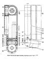
- Figures 6A and 6B are a top view and an aligned cross sectional view of the module in Figures 1A-1C , according to an embodiment of the present invention
- FIG. 7 shows an RCM module under CT guidance according to an embodiment of the present invention.
- Figure 8 shows an RCM module configured for CT-guided prostate brachytherapy, according to an embodiment of the present invention.
- the present invention provides a novel apparatus and method for performing image assisted surgery.
- the invention includes a robotic system or module that can be used to orient an end-effector about two axes intersecting at a fixed geometric point, located distal to the mechanism materializing a pivot point, referred to herein as a Remote Center of Motion (RCM).
- RCM Remote Center of Motion
- An end-effector for example, a robotic tool such as a needle driver, may be mounted upon an RCM module and configured to rotate about the RCM point, which can be conveniently located on the end-effector since this point is remote from the robotic module.
- the present invention is configured to allow two rotational degrees-of-freedom (DOF) with coincident axes at the geometric RCM point.
- DOF degrees-of-freedom
- the position of the pivot is adjustable along one axis by modifying the relative angle between the axes, referred to herein as the adjustment angle.
- the two rotations are not necessarily orthogonal.
- the present invention provides a double belt-drive configuration that helps achieve unrestricted rotation about both axes with no singularity points.
- the present invention also allows the end-effector to rotate about any initial orientation of the RCM mechanism, including folded, extended, or any orientation in between.
- the present invention is capable of uniform mechanical properties at different orientations. Mechanical and/or electronic means can used to limit and set the desired range of motion.
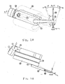
- FIGS 1A - 1C show an isometric, top, and frontal view, respectively, of an RCM module according to an embodiment of the present invention.
- the module or mechanism 100 includes first, second and third arms (also referred to as links and linking units) 10, 18, and 26, respectively.
- First arm 10 is coupled with a base element 9, which can be secured to a base, such as a fixed support or a forerunner robotic component, through the base shaft 1.
- Third arm 26 is configured to receive a holder/driver 32 that holds an end-effector 33, which can be connected on either side of the output shaft 31 or 34 of arm 26.
- a mounting screw 35 is used which can accommodate different end-effectors for different applications.
- the means for coupling the each of the elements are described below in more detail.
- the system 100 is configured to allow two active DOF: a) rotation ⁇ about axis x ⁇ of the base shaft 1 representing a first pivoting axis; and b) rotation ⁇ about axis y of the parallelogram structure formed by arms 18, 26, and holder/driver 32 and/or end-effector 33, representing a second pivoting axis y .
- the two axes intersect at the center of the xyz coordinate system, representing the pivot point or RCM point of the mechanism.
- the Adjustment angle y between the elements 9 and 10 can be adjusted, and the elements 9 and 10 can be locked in a desired relative orientation.
- the adjustment angle ⁇ changes the orientation of the axis x ⁇ and shifts the location of the RCM point along the second pivot axis y .
- This angular adjustment design allows for conveniently setting the pivot point to accommodate different end-effectors while maintaining a compact design.
- One drawback is the degeneration of the orthogonal pivoting axes (x & y
- ⁇ 0) into the non-orthogonal pivot ( x ⁇ & y
- the second pivoting axis y is materialized by the pseudo-parallelogram mechanism described by the links 18, 26, and the end-effector 33 / holder 32.
- the link 18 may be actuated with respect to link 10, and the link 26 maintains its parallel orientation with respect to link 10.
- the end-effector 33 / holder 32 (which is rigidly attached to the output shaft 31, 34) maintains its relative orientation with respect to link 18.
- Output shaft 31, 34 is rotatable, and therefore, the orientation of end-effector 33 / holder 32 with respect to link 26 is adjustable.
- This design allows for rotating the end-effector 33 / holder 32 about an axis y, which is remote from the mechanism. In fact this is the classic RCM design.
- the novelty of the present module is given by the kinematic design and mechanisms used to implement the parallelogram.
- the two pivot axes have unlimited motion, and the axes are able to continuously spin. This is not necessarily important for performing multiple turns, but is important for allowing different operation modes.
- the initial (zero) position of the mechanism 100 can be set at any angle, especially at any ⁇ angle, and can allow the end-effector to pivot from one side to the other of that zero-set direction in space.
- Figures 2A - 2B and 3A - 3B illustrate two examples respectively.
- Figures 2a - 2b respectively show a frontal view of the module and its top, aligned view together with a special end-effector 33 and holder 32.
- the mechanism 100 is shown as mounted inclined ( ⁇ 1 > 0°) with respect to the ground in order to raise the mechanism above the RCM point.
- the holder 32 is shown as connected on the outer side 31 of the module.
- An adjustment of the adjustment angle ⁇ > 0° is used to shift the RCM point along the y axis and place it at the tip of the end-effector 33.
- the RCM is the pivot point for the x ⁇ & y
- the mechanism is inclined ( ⁇ 1 > 0°) with respect to the ground in order to lower the RCM point.
- the outer mounting which avoids interference, could also be employed.
- This unfolded mode with ⁇ 0 near 90° is suitable for situations when the presence of the robotic module above the RCM pivot does not encumber the operation, in procedures such as robotically assisted laparoscopy.
- the folded and unfolded operation modes exemplified above are two preferred arrangements of initial positions, orientation of the module, holder design, and side mountings showing the large variety of potential architectures and application capabilities.
- Figure 4 illustrates the kinematic design of the RCM module according to an embodiment of the present invention.
- Six links (1, 9, 10,18, 26, 31) and five revolute joints (2, 8, 17, 22, 30) are shown.
- One of these joints is passive ( ⁇ adjustment 8) and three other joints (17, 22, 30) are kinematically coupled by belts, so that the mechanism presents only two active DOF (2,17-22-30).
- Module 100 incorporates three main mechanisms: the base adjustment angle, the first pivoting joint of rotation ⁇ along the inclined direction x ⁇ , and the pseudo-parallelogram mechanism.
- the base adjustment angle is realized by changing the angle between the elements 9 and 10 of module 100, which are coupled by the joint 8.
- a convex and respectively a concave cylindrical shape can be mated to implement the revolute joint 8, which can be set and locked at the desired orientation.
- the first pivoting joint of rotation ⁇ along the inclined direction x ⁇ is implemented by the revolute joint 2 acting between the input shaft 1 and the link 9.
- this joint is activated by a worm transmission 3-4 by mounting worm gear 3 on the input shaft 1.
- the worm transmission may be a Bail-Worm type described in U.S. Provisional Patent Application 60/339,247 , entitled “Miniature Ball-Worm Transmission”, filed on October 16,2002.
- a bevel gear transmission 6-7 is used to actuate the worm 4 from the actuator motor 11 of the first axis. These components are arranged so that the adjustment joint 8, the worm 4, and the bevel gear 6 are coaxial.
- the worm 4 and the bevel gear 6 are rigidly attached to one another and supported by a set of bearings 5 located at the center of convex joint surface of 9. This kinematic chain insures that the motion of the actuator motor 11 is transmitted to the output shaft 1 at any set position ⁇ of the adjustment joint 8. In this way the actuator motor 11 could be compactly located in the base link 10, together with the actuator motor 12 of the other pivoting axis.
- the pseudo-parallelogram mechanism is implemented by the remaining components.
- the parallelogram (more easily observed in the frontal views of Figure 1C and Figure 3B ) is formed between the links 18, 26, and the holder 32 and/or end-effector 33.
- An imaginary line connects the output shaft 31 to the RCM pivot.
- Three corner points of this parallelogram are located at joints 17, 22, and 30, and the fourth corner point is imaginary representing the second RCM pivot.
- the parallelogram has equal sides of 100mm.
- the only actuated joint is 17 and the other two are coupled to it through belt-drive mechanisms of 1:1 non-slip transmission ratios implemented by the two belts 19 and 25 (timing belt, chain, cable chain, cable drive, metallic belts, etc.).
- worm mechanism 13-14 is implemented by the mechanism described in provisional patent application 60/339,247 .
- An inverted-pulley mounting design can be used to generate the motion of a parallelogram mechanism with two belt-drives rather than a classic four-bar linkage.
- the motor rotates the link 18 with angle ⁇ ; the link 26 stays parallel to the base 10 at any rotation ⁇ ; and the output shaft 31 maintains its orientation (stays parallel) with respect to link 18.
- the gear 14 spins the link 18 and not the pulley 16, which is attached to the base element 10.
- the second pulley 23 of the first belt 19 tensioned by the idler 21 mounted on the bearing 20, maintains its orientation with respect to the base 10.
- a similar inverted-pulley mounting is then employed for the second 26 and third 31 edge of the parallelogram.
- Link 26 is attached through a shaft to the pulley 23, thus remaining parallel to base 10, and the first pulley 24 of the second belt 25 is connected to the previous link 18.
- the idler 21 supported by the bearing 20 tensions the belt 25, coupling the second pulley 29.
- the output shaft 31, which is attached to the pulley 29 maintains its relative orientation with respect to link 18, closing the pseudo-parallelogram mechanism.
- the combined kinematic design implements an adjustable pivot RCM mechanism of non-orthogonal x ⁇ & y
- the figure depicts an embodiment of the present invention using the Ball-Worm mechanisms.
- the worm gears 3 and 14 have been machined on their shafts 1 and 35, respectively, as represented in Figure 5b .
- the worm gears In the classic worm embodiment, the worm gears have been mounted on the shafts by press fitting and securing with a longitudinal key.
- the bearings used to implement the joints of the kinematic design are labeled with the same number in Figures 5b .
- the shaft 1 is supported by two bearings 2.
- the adjustment joint 8 of the base angle y between the links 9 and 10 can be easily observed in the cross-section A-A, as well as co-axially with the axis of the worm 4.
- the links 18 and 26 can be covered with thin lids 42 and 43, respectively.
- Figure 5B also depicts the inverted-pulley mounting of the belts 19 and 25.
- the pulley 16 is fixed with respect to the base 10 and the gear 14 engages the link 18.
- the pulley 24 is mounted on link 18, and the pulley 23 engages link 26.
- the belts can be tensioned using idlers 21 and 28 mounted on the bearings 20 and 27 supported by the eccentric shafts 37 and 38, respectively, and locked by the flat head screws.
- An angular adjustment at the level of the kinematic joint 22 has been incorporated for adjusting the angle between links 18 and 26 in the assembly process so that link 26 is parallel to the base link 10.
- This allows for mounting the pulleys on their shafts in any initial orientation, for tensioning of the belts, and performance of the "timing" of the belts.
- This mechanism allows for adjusting the angle between the pulley 23 and link 26 and locking it in the desired orientation.
- the pulley 23 is mounted on a shaft 39 presenting a conic surface mated the shaft 40, which is attached to the link 26. The adjustment is performed setting the relative angle between the shafts 39 and 40 and locking it with the screw 41.
- the output shaft presents a symmetric construction so that the end-effector holder can be mounted on the conic surface of either side 31 or side 34 with the screw 35.
- Figure 5B depicts the screw 35 mounted from the side 31 of the shaft 34 for attaching the holder on the side of the shaft 31 (outer side). For mounting on the opposite side (inner side) the screw 35 is reversed, with its head on the side 31 of the shaft.
- Figures 6A and 6B present a top view of the module and an aligned cross section B-B through the center of the adjustment joint.
- Figure 6B depicts the base adjustment arrangement and its bilateral tensioning mechanism, which comprises the plate 46, the dowel pin 47, and the setscrew 48 presenting a tapered point.
- the dowel pin 47 is inserted into the link 9 presenting a radial channel 49 coaxial with the adjustment joint 8. In this way, the pin 47 can sweep the channel adjusting its location so that the tensioning plate 46 maintains a normal direction at the surface of the joint 8.
- the plate 46 is secured at one end into the link 9 by pin 47.
- a hole which is engaged on the conical part of the tapered setscrew 48, which is threaded into link 10. This acts like a wedge between the conical surface of 48 and the hole in plate 46, activated by the setscrew 48.
- the plate 46 is released unlocking the adjustment joint 8, and vice versa for locking.
- Figure 6B also shows the placement of both actuator motors 11 and 12 compactly into the body of link 10, and the motor cover 44 allowing immediate access to the motors. All electric components, motor connectors, and redundant encoder connections, which have been incorporated in the second prototype, are placed in the hollow space of link 10, next to the motors. The wiring cable is released through the hole 45 drilled in the cap 44.
- the RCM module can be a Ball-Worm RCM (BW-RCM), that is, a robotic module for surgical applications that implements a fulcrum point located 100 mm distal to the mechanism.
- BW-RCM Ball-Worm RCM
- the BW-RCM presents a compact design and can be folded into a small structure and can weigh very little (e.g., 175 x 68 x 54 mm structure at only 1.35 Kg).
- the BW-RCM can precisely orient a surgical instrument in space while maintaining the location of one of its points.
- the kinematic architecture of the RCM module of the present invention makes it suitable for minimally invasive applications as well as trocar/needle orientation in percutaneous procedures.
- the RCM module of the present invention can accommodate various end-effectors.
- the RCM may be used in conjunction with the Percutaneous-Access-of-the-Kidney (PAKY) radiolucent needle driver (See: Stoianovici D, Cadeddu JA, Demaree RD, Basile HA, Taylor RH, Whitcomb LL, Sharpe WN, Kavoussi LR: An Efficient Needle Injection Technique and Radiological Guidance Method for Percutaneous Procedures.
- PAKY Percutaneous-Access-of-the-Kidney
- Patent of Invention No. 60/03 8,115 Filed as regular U. S. utility and PCT application on Feb 20,1998 by Johns Hopkins University. Pending U.S. Patent Application Serial No. 09/026,669 filed in February 20, 1998 Publisched as US 6400979 . Published PCT document WO 98/36688 ;) for performing image-guided percutaneous renal access.
- the robot can orient and insert the needle using X-ray fluoroscopy guidance from a C-Arm imager as controlled by the surgeon.
- the system can be used for percutaneous renal access, offering an unquestionable improvement of needle placement accuracy and procedure time while reducing the radiation exposure to patient and urologist.
- the RCM module of the present invention can be used with a special needle driver for computer topography (CT) registration.
- CT computer topography
- the Z-Stage PAKY is a modified version of the PAKY needle driver adapted to implement a CT/MRI registration method in addition to PAKY's needle driving capabilities, constructed in collaboration with the National Science Foundation (NSF) Engineering Research Center for Computer Integrated Surgical Systems and Technology (CISST) at the Johns Hopkins University and the University of Tokyo.
- NSF National Science Foundation
- CISST Computer Integrated Surgical Systems and Technology
- the RCM also operates in a folded mode with non-orthogonal axes.
- Figure 7 shows that under CT guidance, the RCM module of the present invention can be used for kidney and spine percutaneous procedures using a simple method for robot registration in CT and MR imaging system.
- the method uses the laser markers readily available on any CT scanner and does not require imaging thus eliminating radiation exposure.
- the method allows for performing oblique insertions, for which the skin entry point and the target are located in different slices.
- FIG. 8 shows this system configured for CT-guided percutaneous renal access.
- an RCM module which is a compact robotic module capable of orienting an end-effector in two directions in space about a pivot point located distal to the mechanism.
- Applications of the remote pivoting motion include industrial and, most importantly, surgical operations because this type of motion is commonly involved in manual surgical practice.
- the module accommodates various end-effectors and operation modes yielding application flexibility.
- the multiple clinical applications performed with multiple modular arrangements show the versatility of the RCM, its utility and safety for surgical use.
Claims (13)
- Système robotique à centre de mouvement à distance (100), comprenant :une unité de base (9), pouvant tourner sur un premier axe ;plusieurs unités de liaison (10, 18, 26), accouplées les unes aux autres, au moins deux desdites plusieurs unités de liaison étant positionnées parallèlement l'une à l'autre ; etun effecteur terminal (33), accouplé de manière rotative à une deuxième extrémité desdites plusieurs unités de liaison (10, 18, 26), ledit effecteur terminal (33) pouvant tourner sur un deuxième axe en changeant un angle entre chacune desdites plusieurs unités de liaison ;caractérisé en ce qu'une première extrémité desdites plusieurs unités de liaison (10, 18, 26) est accouplée de manière mobile à ladite unité de base par une articulation passive (8), ladite articulation passive (8) changeant une orientation du premier axe par rapport aux unités de liaison en ajustant un angle d'ajustement entre l'unité de base (9) et les plusieurs unités de liaison (10, 18, 26).
- Système selon la revendication 1, dans lequel ledit premier axe et ledit deuxième axe sont orthogonaux.
- Système selon la revendication 1, dans lequel lesdites plusieurs unités de liaison (10, 18, 26) englobent au moins un entraînement par courroie à accouplement (19 ou 25), contrôlant l'angle entre au moins deux desdites plusieurs unités de liaison (10, 18, 26).
- Système selon la revendication 1, comprenant en outre :un premier entraînement à vis sans fin (3, 4), faisant tourner ladite unité de base (9) sur ledit premier axe ;un deuxième entraînement à vis sans fin (13, 14), faisant tourner ladite unité de base (9) sur ledit deuxième axe.
- Système selon la revendication 1, comprenant en outre un moyen de retenue de l'effecteur terminal (32), accouplé de manière rotative à la deuxième extrémité desdites plusieurs unités de liaison (10, 18, 26) pour retenir l'effecteur terminal (33), le contrôle de l'angle entre chacune desdites plusieurs unités de liaison (10, 18, 26) et d'une rotation dudit moyen de retenue de l'effecteur terminal (32) permettant la rotation de l'effecteur terminal (33) autour d'un point du centre de mouvement à distance.
- Système selon la revendication 5, dans lequel ledit moyen de retenue de l'effecteur terminal (32) est positionné sur la deuxième extrémité pour retenir l'effecteur terminal (33) dans une position parallèle à au moins une unité de liaison desdites plusieurs unités de liaison (10, 18, 26).
- Système selon la revendication 2, dans lequel lesdites plusieurs unités de liaison (10, 18, 26) englobent plusieurs articulations (17, 22, 30), chacune desdites plusieurs articulations (17, 22, 30) étant accouplée de manière cinématique.
- Système selon la revendication 5, dans lequel lesdites plusieurs unités de liaison englobent des première (10), deuxième (18) et troisième (26) unités de liaison, ladite première unité de liaison (10) étant accouplée à ladite unité de base (9) par ladite articulation passive (8), ladite deuxième unité de liaison (18) étant accouplée à ladite première unité de liaison (10) par une première articulation tournante (17), ladite troisième unité de liaison (26) étant accouplée à ladite deuxième unité de liaison (18) par une deuxième articulation tournante (22), et ladite troisième unité de liaison (26) étant accouplée audit moyen de retenue de l'effecteur terminal (32) par une troisième articulation tournante (30), chacune des première (17), deuxième (22) et troisième (30) articulations tournantes étant accouplée de manière cinématique.
- Système selon la revendication 8, comprenant en outre :un premier entraînement par courroie (19), connectant lesdites première (17) et deuxième (22) articulations tournantes ;un deuxième entraînement par courroie (25), connectant lesdites deuxième (22) et troisième (30) articulations tournantes.
- Système selon la revendication 4, comprenant en outre un premier moteur (11) accouplé audit premier entraînement à vis sans fin (3, 4) et entraînant celui-ci, et un deuxième moteur (12), accouplé audit deuxième entraînement à vis sans fin (13, 14) et entraînant celui-ci.
- Système selon la revendication 9, comprenant en outre :un premier entraînement à vis sans fin (3, 4), faisant tourner ladite unité de base (9) sur ledit premier axe ;un deuxième entraînement à vis sans fin (13, 14), accouplé audit premier entraînement par courroie (19), pour faire tourner lesdites plusieurs unités de liaison (10, 18, 26) sur ledit deuxième axe ;un premier moteur (11), accouplé audit premier entraînement à vis sans fin (3, 4) et entraînant celui-ci ; etun deuxième moteur (12), accouplé audit deuxième entraînement à vis sans fin (13, 14) et entraînant celui-ci.
- Système selon la revendication 11, comprenant en outre une transmission (5, 6) destinée à s'engager dans ledit premier entraînement à vis sans fin (3, 4) à un quelconque angle d'ajustement réglé.
- Système selon la revendication 12, dans lequel ledit angle d'ajustement est réglé entre 0 et 15 degrés.
Applications Claiming Priority (3)
| Application Number | Priority Date | Filing Date | Title |
|---|---|---|---|
| US35465602P | 2002-02-06 | 2002-02-06 | |
| US354656P | 2002-02-06 | ||
| PCT/US2003/001090 WO2003067341A2 (fr) | 2002-02-06 | 2003-02-06 | Centre telecommande d'un procede et d'un systeme automatises et motorises |
Publications (3)
| Publication Number | Publication Date |
|---|---|
| EP1472579A2 EP1472579A2 (fr) | 2004-11-03 |
| EP1472579A4 EP1472579A4 (fr) | 2009-08-12 |
| EP1472579B1 true EP1472579B1 (fr) | 2013-05-01 |
Family
ID=27734404
Family Applications (1)
| Application Number | Title | Priority Date | Filing Date |
|---|---|---|---|
| EP03710669.7A Expired - Lifetime EP1472579B1 (fr) | 2002-02-06 | 2003-02-06 | Système robotique avec centre de mouvement à distance |
Country Status (7)
| Country | Link |
|---|---|
| US (1) | US7021173B2 (fr) |
| EP (1) | EP1472579B1 (fr) |
| JP (1) | JP2005516786A (fr) |
| CN (1) | CN100349705C (fr) |
| AU (1) | AU2003214837B2 (fr) |
| CA (1) | CA2475239C (fr) |
| WO (1) | WO2003067341A2 (fr) |
Families Citing this family (152)
| Publication number | Priority date | Publication date | Assignee | Title |
|---|---|---|---|---|
| US9050119B2 (en) * | 2005-12-20 | 2015-06-09 | Intuitive Surgical Operations, Inc. | Cable tensioning in a robotic surgical system |
| US6626899B2 (en) | 1999-06-25 | 2003-09-30 | Nidus Medical, Llc | Apparatus and methods for treating tissue |
| US8768516B2 (en) | 2009-06-30 | 2014-07-01 | Intuitive Surgical Operations, Inc. | Control of medical robotic system manipulator about kinematic singularities |
| US7594912B2 (en) * | 2004-09-30 | 2009-09-29 | Intuitive Surgical, Inc. | Offset remote center manipulator for robotic surgery |
| US7766894B2 (en) | 2001-02-15 | 2010-08-03 | Hansen Medical, Inc. | Coaxial catheter system |
| US8414505B1 (en) | 2001-02-15 | 2013-04-09 | Hansen Medical, Inc. | Catheter driver system |
| US7195642B2 (en) | 2001-03-13 | 2007-03-27 | Mckernan Daniel J | Method and apparatus for fixing a graft in a bone tunnel |
| US6517546B2 (en) * | 2001-03-13 | 2003-02-11 | Gregory R. Whittaker | Method and apparatus for fixing a graft in a bone tunnel |
| US7594917B2 (en) * | 2001-03-13 | 2009-09-29 | Ethicon, Inc. | Method and apparatus for fixing a graft in a bone tunnel |
| US7331967B2 (en) * | 2002-09-09 | 2008-02-19 | Hansen Medical, Inc. | Surgical instrument coupling mechanism |
| US6840127B2 (en) * | 2003-02-05 | 2005-01-11 | Michael Julius Moran | Tendon link mechanism with six degrees of freedom |
| US8007511B2 (en) | 2003-06-06 | 2011-08-30 | Hansen Medical, Inc. | Surgical instrument design |
| US7972298B2 (en) * | 2004-03-05 | 2011-07-05 | Hansen Medical, Inc. | Robotic catheter system |
| US7976539B2 (en) * | 2004-03-05 | 2011-07-12 | Hansen Medical, Inc. | System and method for denaturing and fixing collagenous tissue |
| US7971505B2 (en) * | 2004-03-11 | 2011-07-05 | Ntn Corporation | Link actuating device |
| US20050267359A1 (en) * | 2004-05-27 | 2005-12-01 | General Electric Company | System, method, and article of manufacture for guiding an end effector to a target position within a person |
| US10646292B2 (en) | 2004-09-30 | 2020-05-12 | Intuitive Surgical Operations, Inc. | Electro-mechanical strap stack in robotic arms |
| US9261172B2 (en) * | 2004-09-30 | 2016-02-16 | Intuitive Surgical Operations, Inc. | Multi-ply strap drive trains for surgical robotic arms |
| US7763015B2 (en) * | 2005-01-24 | 2010-07-27 | Intuitive Surgical Operations, Inc. | Modular manipulator support for robotic surgery |
| US20060229641A1 (en) * | 2005-01-28 | 2006-10-12 | Rajiv Gupta | Guidance and insertion system |
| JP2016190297A (ja) * | 2015-03-31 | 2016-11-10 | セイコーエプソン株式会社 | ロボットシステム |
| WO2007005976A1 (fr) | 2005-07-01 | 2007-01-11 | Hansen Medical, Inc. | Systeme de catheter robotique |
| GB0521281D0 (en) | 2005-10-19 | 2005-11-30 | Acrobat Company The Ltd | hybrid constrant mechanism |
| US9060678B2 (en) | 2006-06-13 | 2015-06-23 | Intuitive Surgical Operations, Inc. | Minimally invasive surgical system |
| US20100228096A1 (en) * | 2009-03-06 | 2010-09-09 | Ethicon Endo-Surgery, Inc. | Methods and devices for providing access into a body cavity |
| CA2654344C (fr) * | 2006-06-19 | 2015-11-03 | Robarts Research Institute | Appareil de guidage d'un outil medical |
| US8900306B2 (en) | 2006-09-26 | 2014-12-02 | DePuy Synthes Products, LLC | Nucleus anti-expulsion devices and methods |
| CN100425409C (zh) * | 2006-12-13 | 2008-10-15 | 北京航空航天大学 | 一种绳驱动的二维虚拟中心转动机构 |
| US8444631B2 (en) | 2007-06-14 | 2013-05-21 | Macdonald Dettwiler & Associates Inc | Surgical manipulator |
| CA2709634C (fr) * | 2007-12-21 | 2017-04-25 | Benny Hon Bun Yeung | Manipulateur chirurgical |
| US7967549B2 (en) * | 2008-05-15 | 2011-06-28 | The Boeing Company | Robotic system including foldable robotic arm |
| US9610131B2 (en) * | 2008-11-05 | 2017-04-04 | The Johns Hopkins University | Rotating needle driver and apparatuses and methods related thereto |
| US20100126293A1 (en) * | 2008-11-21 | 2010-05-27 | Comau Inc. | Robotic radial tool positioning system |
| US9737334B2 (en) * | 2009-03-06 | 2017-08-22 | Ethicon Llc | Methods and devices for accessing a body cavity |
| US20100228090A1 (en) * | 2009-03-06 | 2010-09-09 | Ethicon Endo-Surgery, Inc. | Methods and devices for providing access into a body cavity |
| US9254123B2 (en) | 2009-04-29 | 2016-02-09 | Hansen Medical, Inc. | Flexible and steerable elongate instruments with shape control and support elements |
| GB0908368D0 (en) | 2009-05-15 | 2009-06-24 | Univ Leuven Kath | Adjustable remote center of motion positioner |
| US20120067354A1 (en) | 2009-06-03 | 2012-03-22 | Moog B.V. | Skewed-axis three degree-of-freedom remote-center gimbal |
| CN102029608A (zh) * | 2009-09-24 | 2011-04-27 | 鸿富锦精密工业(深圳)有限公司 | 机器人 |
| US9474540B2 (en) | 2009-10-08 | 2016-10-25 | Ethicon-Endo-Surgery, Inc. | Laparoscopic device with compound angulation |
| SE0901394A1 (sv) * | 2009-10-30 | 2010-10-12 | Olaf Ruppel | Ställbar arm för gripdon |
| CN101708129B (zh) * | 2009-11-04 | 2012-05-09 | 温州医学院 | 消化道内窥镜介入治疗遥控操作装置 |
| US8376938B2 (en) * | 2009-11-20 | 2013-02-19 | Ethicon Endo-Surgery, Inc. | Discrete flexion head for single port device |
| US8500633B2 (en) * | 2009-12-11 | 2013-08-06 | Ethicon Endo-Surgery, Inc. | Methods and devices for providing surgical access through tissue to a surgical site |
| US8231570B2 (en) * | 2009-12-11 | 2012-07-31 | Ethicon Endo-Surgery, Inc. | Inverted conical expandable retractor |
| US8444557B2 (en) * | 2009-12-11 | 2013-05-21 | Ethicon Endo-Surgery, Inc. | Methods and devices for providing access through tissue to a surgical site |
| US8517932B2 (en) * | 2009-12-11 | 2013-08-27 | Ethicon Endo-Surgery, Inc. | Methods and devices for providing access through tissue to a surgical site |
| US8414483B2 (en) * | 2009-12-11 | 2013-04-09 | Ethicon Endo-Surgery, Inc. | Methods and devices for providing access into a body cavity |
| US8353873B2 (en) * | 2009-12-11 | 2013-01-15 | Ethicon Endo-Surgery, Inc. | Methods and devices for providing access through tissue to a surgical site |
| US8357088B2 (en) * | 2009-12-11 | 2013-01-22 | Ethicon Endo-Surgery, Inc. | Methods and devices for providing access into a body cavity |
| US8435174B2 (en) * | 2009-12-11 | 2013-05-07 | Ethicon Endo-Surgery, Inc. | Methods and devices for accessing a body cavity |
| US8282546B2 (en) * | 2009-12-11 | 2012-10-09 | Ethicon Endo-Surgery, Inc. | Inverted conical expandable retractor with coil spring |
| US8460186B2 (en) * | 2009-12-11 | 2013-06-11 | Ethicon Endo-Surgery, Inc. | Methods and devices for providing access through tissue to a surgical site |
| IT1399603B1 (it) | 2010-04-26 | 2013-04-26 | Scuola Superiore Di Studi Universitari E Di Perfez | Apparato robotico per interventi di chirurgia minimamente invasiva |
| US8562592B2 (en) | 2010-05-07 | 2013-10-22 | Ethicon Endo-Surgery, Inc. | Compound angle laparoscopic methods and devices |
| US9226760B2 (en) | 2010-05-07 | 2016-01-05 | Ethicon Endo-Surgery, Inc. | Laparoscopic devices with flexible actuation mechanisms |
| KR101205364B1 (ko) * | 2010-05-13 | 2012-11-28 | 삼성중공업 주식회사 | 탈부착형 4절 링크기구 구동장치를 갖는 산업용 로봇 |
| KR101550451B1 (ko) * | 2010-08-10 | 2015-09-07 | (주)미래컴퍼니 | 수술용 로봇 암의 rcm 구조 |
| WO2011149260A2 (fr) * | 2010-05-28 | 2011-12-01 | 주식회사 이턴 | Structure à centre de mouvement déporté pour bras de robot chirurgical |
| US8460337B2 (en) | 2010-06-09 | 2013-06-11 | Ethicon Endo-Surgery, Inc. | Selectable handle biasing |
| US20130190774A1 (en) | 2010-08-11 | 2013-07-25 | Ecole Polytechnique Ferderale De Lausanne (Epfl) | Mechanical positioning system for surgical instruments |
| CA2713053A1 (fr) | 2010-08-12 | 2012-02-12 | Socpra-Sciences Et Genie S.E.C. | Dispositif d'orientation d'un objet selon un axe spatial determine |
| CN102371590A (zh) * | 2010-08-25 | 2012-03-14 | 鸿富锦精密工业(深圳)有限公司 | 机器人的臂结构 |
| US10092359B2 (en) | 2010-10-11 | 2018-10-09 | Ecole Polytechnique Federale De Lausanne | Mechanical manipulator for surgical instruments |
| US8603078B2 (en) | 2010-10-13 | 2013-12-10 | Ethicon Endo-Surgery, Inc. | Methods and devices for guiding and supporting surgical instruments |
| US20140039314A1 (en) * | 2010-11-11 | 2014-02-06 | The Johns Hopkins University | Remote Center of Motion Robot for Medical Image Scanning and Image-Guided Targeting |
| WO2012100211A2 (fr) | 2011-01-20 | 2012-07-26 | Hansen Medical, Inc. | Système et procédé de thérapie endoluminale et transluminale |
| CN102229145A (zh) * | 2011-06-23 | 2011-11-02 | 哈尔滨工程大学 | 水下电动机械手二级摆动关节结构 |
| US9696700B2 (en) | 2011-07-27 | 2017-07-04 | Ecole Polytechnique Federale De Lausanne | Mechanical teleoperated device for remote manipulation |
| US9138166B2 (en) | 2011-07-29 | 2015-09-22 | Hansen Medical, Inc. | Apparatus and methods for fiber integration and registration |
| US9227326B2 (en) | 2011-08-11 | 2016-01-05 | The Board Of Trustees Of The Leland Stanford Junior University | Remote center of motion mechanism and method of use |
| US8617176B2 (en) | 2011-08-24 | 2013-12-31 | Depuy Mitek, Llc | Cross pinning guide devices and methods |
| CN103170987B (zh) * | 2011-12-21 | 2015-06-03 | 中国科学院沈阳自动化研究所 | 一种星球表面机械臂采样装置 |
| US9956042B2 (en) | 2012-01-13 | 2018-05-01 | Vanderbilt University | Systems and methods for robot-assisted transurethral exploration and intervention |
| US9687303B2 (en) | 2012-04-20 | 2017-06-27 | Vanderbilt University | Dexterous wrists for surgical intervention |
| US9549720B2 (en) | 2012-04-20 | 2017-01-24 | Vanderbilt University | Robotic device for establishing access channel |
| US9539726B2 (en) * | 2012-04-20 | 2017-01-10 | Vanderbilt University | Systems and methods for safe compliant insertion and hybrid force/motion telemanipulation of continuum robots |
| KR102636293B1 (ko) * | 2012-06-01 | 2024-02-15 | 인튜어티브 서지컬 오퍼레이션즈 인코포레이티드 | 멀티포트 수술 로봇 시스템 구조 |
| KR102530353B1 (ko) * | 2012-06-01 | 2023-05-09 | 인튜어티브 서지컬 오퍼레이션즈 인코포레이티드 | 하드웨어 제한형 원격 중심 로봇 매니퓰레이터용 여유 축 및 자유도 |
| KR102222959B1 (ko) | 2012-06-01 | 2021-03-05 | 인튜어티브 서지컬 오퍼레이션즈 인코포레이티드 | 수술 기구 매니퓰레이터 양태들 |
| BR112015001895A2 (pt) | 2012-08-02 | 2017-07-04 | Koninklijke Philips Nv | sistema cirúrgico robótico, e método robótico |
| CN102922509A (zh) * | 2012-09-27 | 2013-02-13 | 北京航空航天大学 | 一种模块化二自由度虚拟转心并联机构 |
| US20140148673A1 (en) | 2012-11-28 | 2014-05-29 | Hansen Medical, Inc. | Method of anchoring pullwire directly articulatable region in catheter |
| US20140277334A1 (en) | 2013-03-14 | 2014-09-18 | Hansen Medical, Inc. | Active drives for robotic catheter manipulators |
| US9326822B2 (en) | 2013-03-14 | 2016-05-03 | Hansen Medical, Inc. | Active drives for robotic catheter manipulators |
| US20140276936A1 (en) | 2013-03-15 | 2014-09-18 | Hansen Medical, Inc. | Active drive mechanism for simultaneous rotation and translation |
| US9408669B2 (en) | 2013-03-15 | 2016-08-09 | Hansen Medical, Inc. | Active drive mechanism with finite range of motion |
| WO2014155257A1 (fr) | 2013-03-28 | 2014-10-02 | Koninklijke Philips N.V. | Localisation de centre distant robotisé de point de mouvement au moyen d'un trocart personnalisé |
| JP6220085B2 (ja) | 2014-02-03 | 2017-10-25 | ディスタルモーション エスエーDistalmotion Sa | 交換可能な遠位装置を備える機械的遠隔操作デバイス |
| EP3102142A1 (fr) * | 2014-02-04 | 2016-12-14 | Koninklijke Philips N.V. | Définition de centre de mouvement éloigné au moyen de sources lumineuses pour des systèmes de robot |
| US10046140B2 (en) | 2014-04-21 | 2018-08-14 | Hansen Medical, Inc. | Devices, systems, and methods for controlling active drive systems |
| US9549781B2 (en) | 2014-05-30 | 2017-01-24 | The Johns Hopkins University | Multi-force sensing surgical instrument and method of use for robotic surgical systems |
| WO2016009339A1 (fr) * | 2014-07-15 | 2016-01-21 | Koninklijke Philips N.V. | Intégration d'images et commande d'endoscope robotique dans une installation radiographique |
| WO2016030767A1 (fr) | 2014-08-27 | 2016-03-03 | Distalmotion Sa | Système chirurgical pour techniques de microchirurgie |
| TWI675728B (zh) * | 2014-09-30 | 2019-11-01 | 日商精工愛普生股份有限公司 | 機器人及機器人系統 |
| WO2016097868A1 (fr) | 2014-12-19 | 2016-06-23 | Distalmotion Sa | Instrument chirurgical réutilisable pour interventions non effractives |
| EP4289385A3 (fr) | 2014-12-19 | 2024-03-27 | DistalMotion SA | Instrument chirurgical avec organe terminal effecteur articulé |
| EP3232977B1 (fr) | 2014-12-19 | 2020-01-29 | DistalMotion SA | Système d'accueil pour télémanipulateur mécanique |
| EP3232974B1 (fr) | 2014-12-19 | 2018-10-24 | DistalMotion SA | Poignée articulée pour télémanipulateur mécanique |
| EP3232973B1 (fr) | 2014-12-19 | 2020-04-01 | DistalMotion SA | Interface stérile pour instruments chirurgicaux articulés |
| CN105832412B (zh) * | 2015-01-12 | 2018-05-29 | 上银科技股份有限公司 | 用于内视镜定位方法及该定位方法所使用的辅助定位装置 |
| DE102015101018A1 (de) * | 2015-01-23 | 2016-07-28 | MAQUET GmbH | Vorrichtung zum Halten und Bewegen eines Laparoskops während einer Operation |
| KR101666103B1 (ko) * | 2015-02-02 | 2016-10-13 | 하이윈 테크놀로지스 코포레이션 | 내시경의 위치를 결정하는 방법 및 이에 사용되는 위치 결정 보조장치 |
| JP6677970B2 (ja) * | 2015-02-20 | 2020-04-08 | 川崎重工業株式会社 | 産業用ロボット |
| JP2016190294A (ja) * | 2015-03-31 | 2016-11-10 | セイコーエプソン株式会社 | ロボットシステム |
| JP2016190296A (ja) * | 2015-03-31 | 2016-11-10 | セイコーエプソン株式会社 | ロボットシステム |
| JP6582492B2 (ja) * | 2015-03-31 | 2019-10-02 | セイコーエプソン株式会社 | ロボットシステム |
| JP6582491B2 (ja) * | 2015-03-31 | 2019-10-02 | セイコーエプソン株式会社 | ロボット |
| JP2016190298A (ja) * | 2015-03-31 | 2016-11-10 | セイコーエプソン株式会社 | ロボットおよびロボットシステム |
| WO2016162751A1 (fr) | 2015-04-09 | 2016-10-13 | Distalmotion Sa | Instrument manuel articulé |
| EP3280343A1 (fr) | 2015-04-09 | 2018-02-14 | DistalMotion SA | Dispositif mécanique télécommandé pour manipulation à distance |
| JP6528525B2 (ja) * | 2015-04-27 | 2019-06-12 | セイコーエプソン株式会社 | ロボットおよびロボットシステム |
| JP6511939B2 (ja) | 2015-04-27 | 2019-05-15 | セイコーエプソン株式会社 | ロボット |
| EP3290168A4 (fr) | 2015-04-28 | 2018-12-12 | Seiko Epson Corporation | Système de robot et robot |
| JP6582520B2 (ja) * | 2015-04-28 | 2019-10-02 | セイコーエプソン株式会社 | ロボット |
| CN106078675A (zh) * | 2015-04-28 | 2016-11-09 | 精工爱普生株式会社 | 机器人 |
| GB201512966D0 (en) | 2015-07-22 | 2015-09-02 | Cambridge Medical Robotics Ltd | Drive arrangements for robot arms |
| KR200479723Y1 (ko) * | 2015-08-21 | 2016-03-03 | (주)미래컴퍼니 | 수술용 로봇 암의 rcm 구조 |
| WO2017037532A1 (fr) | 2015-08-28 | 2017-03-09 | Distalmotion Sa | Instrument chirurgical doté d'une force d'actionnement accrue |
| JP2017052016A (ja) * | 2015-09-07 | 2017-03-16 | セイコーエプソン株式会社 | ロボット、制御装置およびロボットシステム |
| CN107053252B (zh) | 2015-10-30 | 2021-07-16 | 精工爱普生株式会社 | 机器人 |
| JP2017087301A (ja) * | 2015-11-02 | 2017-05-25 | セイコーエプソン株式会社 | ロボット、制御装置およびロボットシステム |
| JP6766339B2 (ja) * | 2015-11-02 | 2020-10-14 | セイコーエプソン株式会社 | ロボットおよびロボットシステム |
| JP6686644B2 (ja) | 2016-04-06 | 2020-04-22 | セイコーエプソン株式会社 | ロボットおよびロボットシステム |
| CN109310478B (zh) | 2016-05-26 | 2021-08-03 | 西门子保健有限责任公司 | 用于在手术期间保持医疗器械的3d打印的机器人以及其控制 |
| JP2018001313A (ja) * | 2016-06-29 | 2018-01-11 | セイコーエプソン株式会社 | ロボット、ロボット制御装置およびロボットシステム |
| JP2018001315A (ja) * | 2016-06-29 | 2018-01-11 | セイコーエプソン株式会社 | ロボット、制御装置およびロボットシステム |
| JP6769771B2 (ja) * | 2016-07-28 | 2020-10-14 | 株式会社Ihi | 廃棄物解体設備と方法 |
| US10463439B2 (en) | 2016-08-26 | 2019-11-05 | Auris Health, Inc. | Steerable catheter with shaft load distributions |
| US11241559B2 (en) | 2016-08-29 | 2022-02-08 | Auris Health, Inc. | Active drive for guidewire manipulation |
| EP3513300A4 (fr) | 2016-09-16 | 2020-06-03 | Verb Surgical Inc. | Capteur à degrés de liberté multiples |
| ES2903422T3 (es) * | 2016-09-16 | 2022-04-01 | Verb Surgical Inc | Terminación de correa y tensión en disposición de polea para un brazo robótico |
| US11564760B2 (en) | 2016-10-18 | 2023-01-31 | Intuitive Surgical Operations, Inc. | Computer-assisted teleoperated surgery systems and methods |
| WO2018102718A1 (fr) | 2016-12-02 | 2018-06-07 | Vanderbilt University | Endoscope orientable avec manipulateur de continuum |
| CN106584445B (zh) * | 2016-12-16 | 2018-12-25 | 微创(上海)医疗机器人有限公司 | 不动点机构 |
| JP2018187749A (ja) | 2017-05-11 | 2018-11-29 | セイコーエプソン株式会社 | ロボット |
| US11058503B2 (en) | 2017-05-11 | 2021-07-13 | Distalmotion Sa | Translational instrument interface for surgical robot and surgical robot systems comprising the same |
| US10967504B2 (en) | 2017-09-13 | 2021-04-06 | Vanderbilt University | Continuum robots with multi-scale motion through equilibrium modulation |
| JP7013766B2 (ja) * | 2017-09-22 | 2022-02-01 | セイコーエプソン株式会社 | ロボット制御装置、ロボットシステム、及び制御方法 |
| CN107639627A (zh) * | 2017-09-29 | 2018-01-30 | 重庆金山医疗器械有限公司 | 平行四边形传动结构 |
| AU2019218707A1 (en) | 2018-02-07 | 2020-08-13 | Distalmotion Sa | Surgical robot systems comprising robotic telemanipulators and integrated laparoscopy |
| JP7167522B2 (ja) * | 2018-07-27 | 2022-11-09 | セイコーエプソン株式会社 | ロボットアーム |
| CN109394342B (zh) * | 2018-12-18 | 2023-09-05 | 中国科学院苏州生物医学工程技术研究所 | 基于双平行四边形rcm机构的穿刺机器人的进针装置 |
| WO2020144714A1 (fr) * | 2019-01-11 | 2020-07-16 | Indian Council Of Medical Research | Système robotique |
| US11426198B2 (en) * | 2019-07-04 | 2022-08-30 | Aaron Fenster | Biopsy apparatus |
| US11071601B2 (en) | 2019-11-11 | 2021-07-27 | Procept Biorobotics Corporation | Surgical probes for tissue resection with robotic arms |
| CN111166471B (zh) * | 2020-01-09 | 2020-12-22 | 浙江理工大学 | 一种三轴交汇式主被动混合手术持镜臂 |
| CN111227940B (zh) * | 2020-01-23 | 2021-11-30 | 诺创智能医疗科技(杭州)有限公司 | 手术机械臂及手术机器人 |
| US11877818B2 (en) * | 2020-06-26 | 2024-01-23 | Procept Biorobotics Corporation | Integration of robotic arms with surgical probes |
| US11096753B1 (en) | 2020-06-26 | 2021-08-24 | Procept Biorobotics Corporation | Systems and methods for defining and modifying range of motion of probe used in patient treatment |
| CN218128745U (zh) * | 2021-10-03 | 2022-12-27 | 崔迪 | 一种眼科手术机器人 |
| US11844585B1 (en) | 2023-02-10 | 2023-12-19 | Distalmotion Sa | Surgical robotics systems and devices having a sterile restart, and methods thereof |
Family Cites Families (35)
| Publication number | Priority date | Publication date | Assignee | Title |
|---|---|---|---|---|
| US4068763A (en) * | 1976-07-26 | 1978-01-17 | Nasa | Wrist joint assembly |
| US4098001A (en) * | 1976-10-13 | 1978-07-04 | The Charles Stark Draper Laboratory, Inc. | Remote center compliance system |
| US4149278A (en) * | 1977-09-27 | 1979-04-17 | Nasa | Compact artificial hand |
| US4355469A (en) * | 1980-11-28 | 1982-10-26 | The Charles Stark Draper Laboratory, Inc. | Folded remote center compliance device |
| US4477975A (en) * | 1981-05-22 | 1984-10-23 | The Charles Stark Draper Laboratory | Adjustable remote center compliance device |
| US4409736A (en) * | 1981-07-31 | 1983-10-18 | The Charles Stark Draper Laboratory, Inc. | Null seeking system for remote center compliance device |
| EP0078113A3 (fr) * | 1981-10-26 | 1984-05-30 | United Kingdom Atomic Energy Authority | Manipulateur |
| US4537557A (en) * | 1982-04-23 | 1985-08-27 | The Charles Stark Draper Laboratory, Inc. | Remote center compliance gripper system |
| US4556203A (en) * | 1984-01-05 | 1985-12-03 | The Charles Stark Draper Laboratory, Inc. | Remote center compliance device |
| JPS60186384A (ja) * | 1984-03-07 | 1985-09-21 | 株式会社日立製作所 | ロボツトの駆動装置 |
| JP2535366B2 (ja) * | 1988-01-09 | 1996-09-18 | ファナック株式会社 | 産業用ロボットの動作能力確認方法と装置 |
| US5207114A (en) * | 1988-04-21 | 1993-05-04 | Massachusetts Institute Of Technology | Compact cable transmission with cable differential |
| JPH03114460A (ja) * | 1989-09-29 | 1991-05-15 | Mitaka Koki Kk | 医療用三次元定位装置 |
| US5647554A (en) * | 1990-01-23 | 1997-07-15 | Sanyo Electric Co., Ltd. | Electric working apparatus supplied with electric power through power supply cord |
| US5279309A (en) * | 1991-06-13 | 1994-01-18 | International Business Machines Corporation | Signaling device and method for monitoring positions in a surgical operation |
| US5305653A (en) * | 1991-09-30 | 1994-04-26 | Tokico Ltd. | Robot wrist mechanism |
| US5524180A (en) * | 1992-08-10 | 1996-06-04 | Computer Motion, Inc. | Automated endoscope system for optimal positioning |
| US5515478A (en) * | 1992-08-10 | 1996-05-07 | Computer Motion, Inc. | Automated endoscope system for optimal positioning |
| JP3273084B2 (ja) * | 1992-08-20 | 2002-04-08 | オリンパス光学工業株式会社 | 医療器具ホルダ装置 |
| US5397323A (en) * | 1992-10-30 | 1995-03-14 | International Business Machines Corporation | Remote center-of-motion robot for surgery |
| WO1994026167A1 (fr) * | 1993-05-14 | 1994-11-24 | Sri International | Dispositif de positionnement a centre deporte |
| JP3476878B2 (ja) * | 1993-11-15 | 2003-12-10 | オリンパス株式会社 | 手術用マニピュレータ |
| US5876325A (en) * | 1993-11-02 | 1999-03-02 | Olympus Optical Co., Ltd. | Surgical manipulation system |
| US5765444A (en) * | 1995-07-10 | 1998-06-16 | Kensington Laboratories, Inc. | Dual end effector, multiple link robot arm system with corner reacharound and extended reach capabilities |
| US5792135A (en) * | 1996-05-20 | 1998-08-11 | Intuitive Surgical, Inc. | Articulated surgical instrument for performing minimally invasive surgery with enhanced dexterity and sensitivity |
| US5807377A (en) * | 1996-05-20 | 1998-09-15 | Intuitive Surgical, Inc. | Force-reflecting surgical instrument and positioning mechanism for performing minimally invasive surgery with enhanced dexterity and sensitivity |
| US6047610A (en) * | 1997-04-18 | 2000-04-11 | Stocco; Leo J | Hybrid serial/parallel manipulator |
| EP1109497B1 (fr) * | 1998-08-04 | 2009-05-06 | Intuitive Surgical, Inc. | Eléments articules servant à positionner un manipulateur, dans une chirurgie robotise |
| DE19840358A1 (de) * | 1998-09-04 | 2000-03-09 | Motan Holding Gmbh | Verfahren zum Heizen und/oder Trocknen von fließfähigem Schüttgut, vorzugsweise von Kunststoffgranulat, und Heizeinrichtung zur Durchführung des Verfahrens |
| JP2000141270A (ja) * | 1998-11-06 | 2000-05-23 | Matsushita Electric Ind Co Ltd | 多関節型ロボット |
| JP3926501B2 (ja) * | 1998-11-13 | 2007-06-06 | ナブテスコ株式会社 | ロボットアーム及びその駆動装置 |
| JP3326472B2 (ja) * | 1999-11-10 | 2002-09-24 | 独立行政法人 航空宇宙技術研究所 | 多関節ロボット |
| JP2001310287A (ja) * | 2000-04-28 | 2001-11-06 | Shinko Electric Co Ltd | ロボット用アーム装置 |
| CA2410333C (fr) * | 2001-10-31 | 2011-04-26 | Thermo Crs Ltd. | Robot chargeur d'instruments de laboratoire |
| US6675671B1 (en) * | 2002-05-22 | 2004-01-13 | Sandia Corporation | Planar-constructed spatial micro-stage |
-
2003
- 2003-02-06 EP EP03710669.7A patent/EP1472579B1/fr not_active Expired - Lifetime
- 2003-02-06 CN CNB038063514A patent/CN100349705C/zh not_active Expired - Lifetime
- 2003-02-06 WO PCT/US2003/001090 patent/WO2003067341A2/fr active Application Filing
- 2003-02-06 AU AU2003214837A patent/AU2003214837B2/en not_active Expired
- 2003-02-06 JP JP2003566630A patent/JP2005516786A/ja active Pending
- 2003-02-06 CA CA002475239A patent/CA2475239C/fr not_active Expired - Lifetime
- 2003-02-06 US US10/359,284 patent/US7021173B2/en not_active Expired - Lifetime
Also Published As
| Publication number | Publication date |
|---|---|
| JP2005516786A (ja) | 2005-06-09 |
| EP1472579A2 (fr) | 2004-11-03 |
| US20030221504A1 (en) | 2003-12-04 |
| WO2003067341A2 (fr) | 2003-08-14 |
| EP1472579A4 (fr) | 2009-08-12 |
| CN100349705C (zh) | 2007-11-21 |
| AU2003214837B2 (en) | 2008-06-12 |
| CN1642696A (zh) | 2005-07-20 |
| WO2003067341A3 (fr) | 2004-02-26 |
| CA2475239C (fr) | 2008-07-29 |
| AU2003214837A1 (en) | 2003-09-02 |
| CA2475239A1 (fr) | 2003-08-14 |
| US7021173B2 (en) | 2006-04-04 |
Similar Documents
| Publication | Publication Date | Title |
|---|---|---|
| EP1472579B1 (fr) | Système robotique avec centre de mouvement à distance | |
| JP6907299B2 (ja) | 手術器具マニピュレータの態様 | |
| US6997866B2 (en) | Devices for positioning implements about fixed points | |
| JP2020175214A (ja) | ハードウェア拘束リモートセンタロボットマニピュレータのための冗長な軸及び自由度 | |
| US9027431B2 (en) | Remote centre of motion positioner | |
| US10828115B2 (en) | Robotic arm and robotic surgical system | |
| JP6297084B2 (ja) | 小型リストを有する手術ツール | |
| JP4542710B2 (ja) | 外科用マニプレータ | |
| US7204168B2 (en) | Hand controller and wrist device | |
| US8282653B2 (en) | System and methods for controlling surgical tool elements | |
| US9968405B2 (en) | Modular manipulator support for robotic surgery | |
| US6406472B1 (en) | Remote center positioner | |
| US5800423A (en) | Remote center positioner with channel shaped linkage element | |
| US8167872B2 (en) | Center robotic arm with five-bar spherical linkage for endoscopic camera | |
| US20080314181A1 (en) | Robotic Manipulator with Remote Center of Motion and Compact Drive | |
| US20070173977A1 (en) | Center robotic arm with five-bar spherical linkage for endoscopic camera | |
| EP3831543A1 (fr) | Centre distant de mécanisme de mouvement | |
| US20230149106A1 (en) | Surgical robotic system comprising strut assembly |
Legal Events
| Date | Code | Title | Description |
|---|---|---|---|
| PUAI | Public reference made under article 153(3) epc to a published international application that has entered the european phase |
Free format text: ORIGINAL CODE: 0009012 |
|
| 17P | Request for examination filed |
Effective date: 20040809 |
|
| AK | Designated contracting states |
Kind code of ref document: A2 Designated state(s): AT BE BG CH CY CZ DE DK EE ES FI FR GB GR HU IE IT LI LU MC NL PT SE SI SK TR |
|
| A4 | Supplementary search report drawn up and despatched |
Effective date: 20090709 |
|
| 17Q | First examination report despatched |
Effective date: 20091030 |
|
| REG | Reference to a national code |
Ref country code: DE Ref legal event code: R079 Ref document number: 60343936 Country of ref document: DE Free format text: PREVIOUS MAIN CLASS: G05B0001000000 Ipc: A61B0019000000 |
|
| GRAP | Despatch of communication of intention to grant a patent |
Free format text: ORIGINAL CODE: EPIDOSNIGR1 |
|
| RIC1 | Information provided on ipc code assigned before grant |
Ipc: B25J 9/10 20060101ALI20120903BHEP Ipc: B25J 17/02 20060101ALI20120903BHEP Ipc: B25J 9/06 20060101ALI20120903BHEP Ipc: A61B 19/00 20060101AFI20120903BHEP Ipc: B25J 18/00 20060101ALI20120903BHEP |
|
| GRAJ | Information related to disapproval of communication of intention to grant by the applicant or resumption of examination proceedings by the epo deleted |
Free format text: ORIGINAL CODE: EPIDOSDIGR1 |
|
| GRAP | Despatch of communication of intention to grant a patent |
Free format text: ORIGINAL CODE: EPIDOSNIGR1 |
|
| RAP1 | Party data changed (applicant data changed or rights of an application transferred) |
Owner name: THE JOHNS HOPKINS UNIVERSITY |
|
| RIN1 | Information on inventor provided before grant (corrected) |
Inventor name: TAYLOR, RUSSELL, H. Inventor name: STOIANOVICI, DAN Inventor name: KAVOUSSI, LOUIS, R. Inventor name: WHITCOMB, LOUIS, L. Inventor name: MAZILU, DUMITRU |
|
| GRAS | Grant fee paid |
Free format text: ORIGINAL CODE: EPIDOSNIGR3 |
|
| GRAA | (expected) grant |
Free format text: ORIGINAL CODE: 0009210 |
|
| AK | Designated contracting states |
Kind code of ref document: B1 Designated state(s): AT BE BG CH CY CZ DE DK EE ES FI FR GB GR HU IE IT LI LU MC NL PT SE SI SK TR |
|
| REG | Reference to a national code |
Ref country code: GB Ref legal event code: FG4D |
|
| REG | Reference to a national code |
Ref country code: CH Ref legal event code: EP Ref country code: AT Ref legal event code: REF Ref document number: 609394 Country of ref document: AT Kind code of ref document: T Effective date: 20130515 |
|
| REG | Reference to a national code |
Ref country code: IE Ref legal event code: FG4D |
|
| REG | Reference to a national code |
Ref country code: DE Ref legal event code: R096 Ref document number: 60343936 Country of ref document: DE Effective date: 20130627 |
|
| REG | Reference to a national code |
Ref country code: AT Ref legal event code: MK05 Ref document number: 609394 Country of ref document: AT Kind code of ref document: T Effective date: 20130501 |
|
| REG | Reference to a national code |
Ref country code: NL Ref legal event code: VDEP Effective date: 20130501 |
|
| PG25 | Lapsed in a contracting state [announced via postgrant information from national office to epo] |
Ref country code: FI Free format text: LAPSE BECAUSE OF FAILURE TO SUBMIT A TRANSLATION OF THE DESCRIPTION OR TO PAY THE FEE WITHIN THE PRESCRIBED TIME-LIMIT Effective date: 20130501 Ref country code: PT Free format text: LAPSE BECAUSE OF FAILURE TO SUBMIT A TRANSLATION OF THE DESCRIPTION OR TO PAY THE FEE WITHIN THE PRESCRIBED TIME-LIMIT Effective date: 20130902 Ref country code: ES Free format text: LAPSE BECAUSE OF FAILURE TO SUBMIT A TRANSLATION OF THE DESCRIPTION OR TO PAY THE FEE WITHIN THE PRESCRIBED TIME-LIMIT Effective date: 20130812 Ref country code: GR Free format text: LAPSE BECAUSE OF FAILURE TO SUBMIT A TRANSLATION OF THE DESCRIPTION OR TO PAY THE FEE WITHIN THE PRESCRIBED TIME-LIMIT Effective date: 20130802 Ref country code: SI Free format text: LAPSE BECAUSE OF FAILURE TO SUBMIT A TRANSLATION OF THE DESCRIPTION OR TO PAY THE FEE WITHIN THE PRESCRIBED TIME-LIMIT Effective date: 20130501 Ref country code: SE Free format text: LAPSE BECAUSE OF FAILURE TO SUBMIT A TRANSLATION OF THE DESCRIPTION OR TO PAY THE FEE WITHIN THE PRESCRIBED TIME-LIMIT Effective date: 20130501 Ref country code: AT Free format text: LAPSE BECAUSE OF FAILURE TO SUBMIT A TRANSLATION OF THE DESCRIPTION OR TO PAY THE FEE WITHIN THE PRESCRIBED TIME-LIMIT Effective date: 20130501 |
|
| PG25 | Lapsed in a contracting state [announced via postgrant information from national office to epo] |
Ref country code: BG Free format text: LAPSE BECAUSE OF FAILURE TO SUBMIT A TRANSLATION OF THE DESCRIPTION OR TO PAY THE FEE WITHIN THE PRESCRIBED TIME-LIMIT Effective date: 20130801 |
|
| PG25 | Lapsed in a contracting state [announced via postgrant information from national office to epo] |
Ref country code: BE Free format text: LAPSE BECAUSE OF FAILURE TO SUBMIT A TRANSLATION OF THE DESCRIPTION OR TO PAY THE FEE WITHIN THE PRESCRIBED TIME-LIMIT Effective date: 20130501 Ref country code: CZ Free format text: LAPSE BECAUSE OF FAILURE TO SUBMIT A TRANSLATION OF THE DESCRIPTION OR TO PAY THE FEE WITHIN THE PRESCRIBED TIME-LIMIT Effective date: 20130501 Ref country code: DK Free format text: LAPSE BECAUSE OF FAILURE TO SUBMIT A TRANSLATION OF THE DESCRIPTION OR TO PAY THE FEE WITHIN THE PRESCRIBED TIME-LIMIT Effective date: 20130501 Ref country code: SK Free format text: LAPSE BECAUSE OF FAILURE TO SUBMIT A TRANSLATION OF THE DESCRIPTION OR TO PAY THE FEE WITHIN THE PRESCRIBED TIME-LIMIT Effective date: 20130501 Ref country code: EE Free format text: LAPSE BECAUSE OF FAILURE TO SUBMIT A TRANSLATION OF THE DESCRIPTION OR TO PAY THE FEE WITHIN THE PRESCRIBED TIME-LIMIT Effective date: 20130501 |
|
| PG25 | Lapsed in a contracting state [announced via postgrant information from national office to epo] |
Ref country code: NL Free format text: LAPSE BECAUSE OF FAILURE TO SUBMIT A TRANSLATION OF THE DESCRIPTION OR TO PAY THE FEE WITHIN THE PRESCRIBED TIME-LIMIT Effective date: 20130501 |
|
| PLBE | No opposition filed within time limit |
Free format text: ORIGINAL CODE: 0009261 |
|
| STAA | Information on the status of an ep patent application or granted ep patent |
Free format text: STATUS: NO OPPOSITION FILED WITHIN TIME LIMIT |
|
| 26N | No opposition filed |
Effective date: 20140204 |
|
| REG | Reference to a national code |
Ref country code: DE Ref legal event code: R097 Ref document number: 60343936 Country of ref document: DE Effective date: 20140204 |
|
| PG25 | Lapsed in a contracting state [announced via postgrant information from national office to epo] |
Ref country code: MC Free format text: LAPSE BECAUSE OF FAILURE TO SUBMIT A TRANSLATION OF THE DESCRIPTION OR TO PAY THE FEE WITHIN THE PRESCRIBED TIME-LIMIT Effective date: 20130501 Ref country code: LU Free format text: LAPSE BECAUSE OF FAILURE TO SUBMIT A TRANSLATION OF THE DESCRIPTION OR TO PAY THE FEE WITHIN THE PRESCRIBED TIME-LIMIT Effective date: 20140206 |
|
| REG | Reference to a national code |
Ref country code: CH Ref legal event code: PL |
|
| PG25 | Lapsed in a contracting state [announced via postgrant information from national office to epo] |
Ref country code: CH Free format text: LAPSE BECAUSE OF NON-PAYMENT OF DUE FEES Effective date: 20140228 Ref country code: LI Free format text: LAPSE BECAUSE OF NON-PAYMENT OF DUE FEES Effective date: 20140228 |
|
| REG | Reference to a national code |
Ref country code: IE Ref legal event code: MM4A |
|
| PG25 | Lapsed in a contracting state [announced via postgrant information from national office to epo] |
Ref country code: IE Free format text: LAPSE BECAUSE OF NON-PAYMENT OF DUE FEES Effective date: 20140206 |
|
| REG | Reference to a national code |
Ref country code: FR Ref legal event code: PLFP Year of fee payment: 14 |
|
| PG25 | Lapsed in a contracting state [announced via postgrant information from national office to epo] |
Ref country code: CY Free format text: LAPSE BECAUSE OF FAILURE TO SUBMIT A TRANSLATION OF THE DESCRIPTION OR TO PAY THE FEE WITHIN THE PRESCRIBED TIME-LIMIT Effective date: 20130501 |
|
| PG25 | Lapsed in a contracting state [announced via postgrant information from national office to epo] |
Ref country code: HU Free format text: LAPSE BECAUSE OF FAILURE TO SUBMIT A TRANSLATION OF THE DESCRIPTION OR TO PAY THE FEE WITHIN THE PRESCRIBED TIME-LIMIT; INVALID AB INITIO Effective date: 20030206 Ref country code: TR Free format text: LAPSE BECAUSE OF FAILURE TO SUBMIT A TRANSLATION OF THE DESCRIPTION OR TO PAY THE FEE WITHIN THE PRESCRIBED TIME-LIMIT Effective date: 20130501 |
|
| REG | Reference to a national code |
Ref country code: FR Ref legal event code: PLFP Year of fee payment: 15 |
|
| REG | Reference to a national code |
Ref country code: FR Ref legal event code: PLFP Year of fee payment: 16 |
|
| PGFP | Annual fee paid to national office [announced via postgrant information from national office to epo] |
Ref country code: GB Payment date: 20220225 Year of fee payment: 20 Ref country code: DE Payment date: 20220225 Year of fee payment: 20 |
|
| PGFP | Annual fee paid to national office [announced via postgrant information from national office to epo] |
Ref country code: IT Payment date: 20220222 Year of fee payment: 20 Ref country code: FR Payment date: 20220223 Year of fee payment: 20 |
|
| REG | Reference to a national code |
Ref country code: DE Ref legal event code: R071 Ref document number: 60343936 Country of ref document: DE |
|
| REG | Reference to a national code |
Ref country code: GB Ref legal event code: PE20 Expiry date: 20230205 |
|
| PG25 | Lapsed in a contracting state [announced via postgrant information from national office to epo] |
Ref country code: GB Free format text: LAPSE BECAUSE OF EXPIRATION OF PROTECTION Effective date: 20230205 |