EP1470070B1 - Dokumentenvernichter mit einzelblattzufuhr von gestapeltem blattgut - Google Patents
Dokumentenvernichter mit einzelblattzufuhr von gestapeltem blattgut Download PDFInfo
- Publication number
- EP1470070B1 EP1470070B1 EP03731706A EP03731706A EP1470070B1 EP 1470070 B1 EP1470070 B1 EP 1470070B1 EP 03731706 A EP03731706 A EP 03731706A EP 03731706 A EP03731706 A EP 03731706A EP 1470070 B1 EP1470070 B1 EP 1470070B1
- Authority
- EP
- European Patent Office
- Prior art keywords
- pressure
- sheet
- support surface
- link
- stack
- Prior art date
- Legal status (The legal status is an assumption and is not a legal conclusion. Google has not performed a legal analysis and makes no representation as to the accuracy of the status listed.)
- Expired - Lifetime
Links
- 230000009471 action Effects 0.000 claims description 2
- 230000009467 reduction Effects 0.000 claims description 2
- 238000006073 displacement reaction Methods 0.000 claims 9
- 230000013011 mating Effects 0.000 claims 1
- 238000000034 method Methods 0.000 abstract description 4
- 230000006378 damage Effects 0.000 description 7
- 238000007639 printing Methods 0.000 description 7
- 230000007246 mechanism Effects 0.000 description 4
- 238000012545 processing Methods 0.000 description 4
- 230000001360 synchronised effect Effects 0.000 description 4
- 230000000454 anti-cipatory effect Effects 0.000 description 3
- 230000008878 coupling Effects 0.000 description 3
- 238000010168 coupling process Methods 0.000 description 3
- 238000005859 coupling reaction Methods 0.000 description 3
- 238000013461 design Methods 0.000 description 3
- 238000003780 insertion Methods 0.000 description 3
- 230000037431 insertion Effects 0.000 description 3
- 230000008569 process Effects 0.000 description 3
- 238000010276 construction Methods 0.000 description 2
- 238000007790 scraping Methods 0.000 description 2
- 238000012546 transfer Methods 0.000 description 2
- 240000006829 Ficus sundaica Species 0.000 description 1
- 208000027418 Wounds and injury Diseases 0.000 description 1
- 238000013459 approach Methods 0.000 description 1
- 230000003247 decreasing effect Effects 0.000 description 1
- 230000001419 dependent effect Effects 0.000 description 1
- 238000005516 engineering process Methods 0.000 description 1
- 208000014674 injury Diseases 0.000 description 1
- NJPPVKZQTLUDBO-UHFFFAOYSA-N novaluron Chemical compound C1=C(Cl)C(OC(F)(F)C(OC(F)(F)F)F)=CC=C1NC(=O)NC(=O)C1=C(F)C=CC=C1F NJPPVKZQTLUDBO-UHFFFAOYSA-N 0.000 description 1
- 230000000630 rising effect Effects 0.000 description 1
Images






Classifications
-
- B—PERFORMING OPERATIONS; TRANSPORTING
- B02—CRUSHING, PULVERISING, OR DISINTEGRATING; PREPARATORY TREATMENT OF GRAIN FOR MILLING
- B02C—CRUSHING, PULVERISING, OR DISINTEGRATING IN GENERAL; MILLING GRAIN
- B02C18/00—Disintegrating by knives or other cutting or tearing members which chop material into fragments
- B02C18/06—Disintegrating by knives or other cutting or tearing members which chop material into fragments with rotating knives
- B02C18/16—Details
- B02C18/22—Feed or discharge means
- B02C18/2225—Feed means
- B02C18/2283—Feed means using rollers
-
- B—PERFORMING OPERATIONS; TRANSPORTING
- B02—CRUSHING, PULVERISING, OR DISINTEGRATING; PREPARATORY TREATMENT OF GRAIN FOR MILLING
- B02C—CRUSHING, PULVERISING, OR DISINTEGRATING IN GENERAL; MILLING GRAIN
- B02C18/00—Disintegrating by knives or other cutting or tearing members which chop material into fragments
- B02C18/0007—Disintegrating by knives or other cutting or tearing members which chop material into fragments specially adapted for disintegrating documents
-
- B—PERFORMING OPERATIONS; TRANSPORTING
- B02—CRUSHING, PULVERISING, OR DISINTEGRATING; PREPARATORY TREATMENT OF GRAIN FOR MILLING
- B02C—CRUSHING, PULVERISING, OR DISINTEGRATING IN GENERAL; MILLING GRAIN
- B02C18/00—Disintegrating by knives or other cutting or tearing members which chop material into fragments
- B02C18/0007—Disintegrating by knives or other cutting or tearing members which chop material into fragments specially adapted for disintegrating documents
- B02C2018/003—Removing clips, pins or staples before disintegrating
Definitions
- the invention relates to a document shredder, namely a device for im Substantial sheet by sheet destruct of stacked sheet Sheet material according to PCT WO 01/54820 A1.
- the sheet material is his cutting - possibly also for cross-cut - not in more or less isolated Leaf shape by hand but driven by a motor automatically from a stack of leaves fed.
- the known document shredder automatically pulls through preferably a continuously rotating friction wheel drive sheet by sheet from the bottom of the From the stack of leaves, folds the sheet in the middle and leads it with anticipatory crease the below the support for the stack of sheet stacker too.
- the occasional sheet feeder to the cutting unit can also be used for a large Scaling a simple cutting unit of conventional document shredders use. Leave the trigger and the fold as well as the feed to the cutting unit in a simple design by a continuously rotating friction drive machine realize. The sheet by sheet destruction of the stack of sheets takes Although a certain time to complete, but after the sheet stacking feed completely automatically without manual assistance with structurally comparatively low Effort.
- Essential part of the individual sheets from the bottom of the stack of sheet material and withdrawing transport means are two counter-clockwise at constant circulation speed driven carrier rollers. They grip with their as friction lining or perimeter equipped with grip teeth that in the sheet stack below Leaf on its overlying surface and push it from its two sides towards the leaf center. The middle of the sheet is thereby directed towards the passage deflected between the two drive rollers. The by this deflection resulting Blattzwickel or folding apex is between the two drive rollers through in the direction away from the stack down the underlying direction Cutting unit of conventional design by the exerted by the friction rollers Supplied thrust. There, the anticipatory Faltscheitel of the cutting discs of the cutting mechanism. The folded sheet is doubled Leaf sides lying on each other pulled by the cutting discs through the cutting unit.
- the known document shredder contains a stack of sheets in the middle of above acting Andruckvocardi. This is above the gap positioned above the two drive rollers and applied there the sheet material stack downward. It is their main task at the bottom of the Sheet stack peeled single sheet forming a downward direction Cutting mechanism towards and from the sheet material stack resulting gusset or folding apex force.
- the present invention has for its object to provide a pressure device create, which when removing the stack lying in the bottom sheet generation a pointing in the direction of the cutting unit toward the leaf gusset or Faltscheitels even safer and more efficiently accomplished, the trigger device for Avoidance of injury to the outside shields and easy operation with good work safety.
- the solution allows it, the supplied Blattgutstapel during the Vemichtungsvorganges after to be covered externally by means of pivoting manually operated closure elements.
- the closure elements shield in the direction of each other in the manner of hinged lid halves the sheet stack to the loading side, so after above. Furthermore, they control both in their closed position and in their opening position. loading or loading as well as their manual transfer into their opening and in its closed position, the positioning of the printing elements. At her opening movement not only do the closing elements give unrestricted access free to the sheet stacking pad of the document shredder. Rather, remove them at their Opening movement and the printing elements from the access path to the sheet stacking pad. This allows the special gear technology linkage of the printing elements. They are automatically at the opening pivoting of the closure elements from the Auflageraum removed and are therefore not hindering the loading process.
- the closure elements When the closure elements are transferred into their closed position, the closure elements control the pressure elements as a function of the height of the to be destroyed Sheet stack in a suitable pressure position. In addition, they control after achieved Closed position the pressure of the printing elements on top of the sheet stack. This control is accomplished in a manner that is automatic without separate, from the outside attacking drive means each an optimal Anyakwolf and pressure-positioning of the printing elements ensures.
- the document shredder 1 includes a support surface 4 with in a center in the support surface 4 positioned passage opening 5. This is used for the discharge of the two driver rollers 2,3 withdrawn from the bottom 6 of the sheet stack 7 Single sheets.
- the driver rollers 2,3 are partially within the passage opening 5 and stand with their upper outer circumference on the support surface 4 in the direction on the stack of leaves 7 addition. They are continuously in opposite directions in the directions of rotation 48.49 revolving driven.
- Closure element 11 is hereinafter also referred to as "closure lid” for the sake of simplicity. designated.
- the closure elements 11 are pivotable about the pivot axis 12 mounted on the respective bearing base 10. Close in its closed position (Fig. 1 to 5) the closure elements 11 the support space 9 upwards. At the destruction process the support room 9 is not accessible.
- the two are the support space 9 flanking bearing pedestals 10 each have a closure element 11 to the respective Swivel axle 12 pivotally assigned.
- Their pivot axes 12 flank the Supporting space 9 for the sheet stack 7 on both sides. They run parallel to the not shown, perpendicular to the image plane of Fig. 1 extending slot direction of Passage opening 5 in the support surface. 4
- the document shredder contains between its support surface 4 and the closure elements 11 positioned printing elements 15. These have the form of pressure plates on, which are perpendicular to the presentation of the drawing figures almost extend over the greater part of the width extension of the closure elements 11.
- the printing elements 15 act on the sheet stack 7 in the direction of the support surface 4.
- the respective bearing base 10 facing sides of the two Drukkieri 15 are formed as socket-like joint carrier holder 16.
- Each articulated carrier holder 16 includes perpendicular to the drawing planes extending pivot axes 17,18 for the storage of a control link 19 and a Hublenkers 20 - both pivotable in the image plane.
- each articulated carrier holder 16 store only in the support space 9 protruding ends of the control link 19 and the Hublenkers 20.
- the respective socket-side (bearing base 10) ends of the control link 19 and of the stub shaft 20 (FIGS. 2 to 9) are pivot axes extending perpendicular to the image plane 21 and 22 pivotally mounted on the bearing base 10.
- the connecting link 23 between a closure element 11 and its associated Hublenker 20 includes at its bearing base end a rotary push joint 24.
- the rotary push joint 24 facing away from the upper end of the connecting link 23 is pivotally connected to the closure member 11 about the pivot axis 25.
- the pivot axis 25 extends like all other pivot axes perpendicular to the drawing planes.
- connection between connecting link 23 and Hublenker 20 attacks an effective as a lever extension spur 26 of the Hublenkers 20 at.
- This Extension spur 26 is in the manner of a stubby lever arm on the sokkel workede (Bearing base 10) hinge axis 22 of the Hublenkers 20 also forms with the Hublenker 20 a two-armed lever.
- the rotary push joint 24 of the connecting link 23 with the hinge 45 as a rotary joint part acts on the free end of the extension spur 26 attacking as to the joint 45 effective lever on the handlebar 20.
- the thrust direction of the rotary joint 24 extends in the longitudinal direction of the connecting link 23rd
- the bearing pedestal 10 are in side walls of a feed slot 27 to the support surface 4 integrated or firmly connected.
- Each pressure element 15 extends with the hinge carrier holder 16 facing away from it, projecting into the support space 9 projecting end 29 to the passage opening 5 for the withdrawn Blattgut.
- a tension spring 28 is effective between control link 19 and pressure element 15, a tension spring 28 is effective.
- the Tension spring 28 acts on the pressure element 15 in its edition on the sheet stack. 7 pioneering direction. She tries so to speak, the pressure element 15 with its free cantilever 29 to lift up. In conjunction with the four-bar linkage 10,19,16,20 results from the tension spring 28 for the total movement of the Drukkimplantations 15 an additional pressure down on the paper stack. 7
- the tension spring 28 is with its the control arm 19 facing the end approximately midway fixed to the hinge ends 17,21 of the control link 19 at this.
- the fixation takes place on a projecting in the direction of the closure element 11 Fixiervorsprung 30th
- the pressure element 15 facing the end of the control link 19 is about his there associated pivot axis 17 to form a in the direction of the contact surface 4 angled protruding dog stop 37 addition.
- the driver stop 37 strikes at above the frame-side pivot bearing 21 of the control handle 19 lying pressure element side pivot axis 18 of the Hublenkers 20 and partially pivoted (Fig. 9,10) closure element 11 with correspondingly upstanding Positioning of the pressure element side pivot bearing 17 of the control arm 19 for its pivotal movement on a pressure element side counter-stop 38 in the region of the joint carrier 16.
- the Mitaueranschlag 37 transmits with further opening pivoting 47 of the closure element 11 thereby generated Torque to further increase the pressure element 15 in from the support surface 4 opposite direction. ( Figure 9).
- the control link 19 is thus at its end facing away from the pressure element 15 with its control arm 46 via its pivot bearing 21 on the bearing base 10 addition.
- the Control arm 46 further includes at its end remote from the pivot axis 21 a Sales area 40 and an end stop surface 41 and the stand in a blunt Angle to each other. At over the summit of his pivoting path (Fig. 12) going out Aufschwenk ein of the closure element 11 meets the at the outer end of the Closing element 11 arranged end stop 43 on the shoulder surface 41 of Control arm 46.
- the two closure elements 11 of the document shredder respectively act correspondingly together. That means the swinging motion one of the closure elements 11 synchronously an analogous Aufschwenkamba also the other closure element 11 by a synchronous drive, not shown here causes.
- a Buchstoff für between two closure elements 11 provides for a respective same angular position of the closure elements 11 with respect to their Swivel axes 12, even if a pivoting only one of the two closure elements 11 is done by the operator. This is how the synchronous swinging turns causes.
- the sheet stack 7 is located in extreme open position closure elements 11 and pressure elements 15 (FIG. 13) are inserted from above into the support space 9. Subsequently pivot the closure elements 11 from their upright opening position in the substantially horizontal closed position (Fig. 1). These Pivoting movement is synchronous by both closure elements 11, each with the same Swing angle completed. In this case, the two closure elements 11 associated pressure elements 15 taken in the manner described.
- the on the loading operation the following closure position is shown in Fig. 1. Act on it both pressure elements 15 with their in the direction of the region of the passage opening 5 downwardly inclined cantilever 29 the sheet stack 7 in its center.
- This overall construction also allows a single sheet feeder through two individual lids to.
Landscapes
- Engineering & Computer Science (AREA)
- Food Science & Technology (AREA)
- Crushing And Pulverization Processes (AREA)
- Debarking, Splitting, And Disintegration Of Timber (AREA)
- Treatment Of Fiber Materials (AREA)
- Sheets, Magazines, And Separation Thereof (AREA)
- Basic Packing Technique (AREA)
- Pile Receivers (AREA)
- Containers And Packaging Bodies Having A Special Means To Remove Contents (AREA)
Description
- Fig. 1
- einen Längsschnitt durch die erfindungsgemäße Vorrichtung zu Beginn eines Arbeitszyklus zur Vernichtung eines Blattstapels.
- Fig. 2
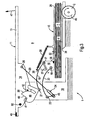
- in vergrößerter Form den linken Teil der Vorrichtung nach Fig. 1, deren rechten Teil man sich spiegelbildlich analog (s. Fig. 1) vorzustellen hat.
- Fig. 3
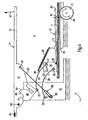
- eine Darstellung analog Fig. 2 mit bereits deutlich reduzierter Höhe des Blattstapels, d.h. nach bereits mehr als hälftiger Vernichtung der in Fig. 1 und Fig. 2 dargestellten Stapelhöhe.
- Fig. 4
- eine Darstellung analog Fig. 3 bei noch weiter bis auf wenige Blatt abgearbeiteter Stapelhöhe.
- Fig. 5
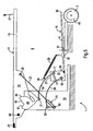
- eine Darstellung analog Fig. 2 bis 4 nach Abzug und Vernichtung auch des letzten Blattes des ursprünglichen Blattstapels (Fig. 1,2).
- Fig. 6
- eine Darstellung analog Fig. 2 bis 5, bei welcher das linke Verschlusselement - nachstehend der Einfachheit halber auch als "Verschlussdeckel" bezeichnet - um wenige Winkelgrade aus seiner in den Fig. 1 bis 5 dargestellten Schließstellung in Richtung auf seine Öffnungsstellung hochgeschwenkt ist und das Druckelement mit anhebt.
- Fig. 7
- eine Darstellung analog Fig. 6 nach Öffnung des Verschlussdeckels über bereits einen größeren Schwenkwinkel als in Fig. 6 und das Druckelement weiter anhebt.
- Fig. 8
- der Führungsvorsprung (50) setzt auf den Steuerarm (46), insbesondere auf die Steuerkurve (39) auf.
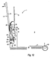
- Fig. 9 bis 13
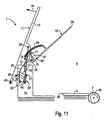
- noch größere Öffnungsstellungen des Verschlussdeckels analog Fig. 6 bis zur maximalen Öffnungsstellung in Fig. 13, bei welcher die Auflage für einen neuen Blattgutstapel und der Zuführungsschacht für den Blattgutstapel vollständig unbesetzt sind.
- Fig. 14
- in vereinzelter Form die wesentlichen Gestell- und Bedienungsteile der erfindungsgemäßen Vorrichtung.
- Fig. 15 und 16
- in vereinzelter Darstellung die wesentlichen Getriebeglieder für die Halterung der beiden Druckelemente an ihren Lagersockeln und
- Fig. 17
- das den Schwenkantrieb übertragende Verbindungsglied zwischen einem Verschlusselement und dem Koppelgetriebe zur Schwenksteuerung eines Druckelements.
- 1
- Dokumentenvernichter
- 2
- Mitnehmerrolle
- 3
- Mitnehmerrolle
- 4
- Auflagefläche
- 5
- Durchlassöffnung
- 6
- Unterseite
- 7
- Blattstapel
- 8
- Zuführrichtung
- 9
- Auflageraum
- 10
- Lagersockel
- 11
- Verschlusselement
- 12
- Schwenkachse
- 13
- Abdeckausleger
- 14
- Schwenklagerende
- 15
- Druckelement
- 16
- Gelenkträger
- 17
- Schwenkachse
- 18
- Schwenkachse
- 19
- Steuerlenker
- 20
- Hublenker
- 21
- Schwenkachse
- 22
- Schwenkachse
- 23
- Verbindungslenker
- 24
- Drehschubgelenk
- 25
- Schwenkachse
- 26
- Verlängerungssporn
- 27
- Zuführungsschacht
- 28
- Zugfeder
- 29
- Auskragende
- 30
- Fixierpunkt
- 31
- Stapelhöhe
- 32
- Neigungswinkel
- 33
- Mittl. Stapeldicke
- 34
- Abstand
- 35
- Neigungswinkel
- 36
- Abstreifkante
- 37
- Mitnehmeranschlag
- 38
- Gegenanschlag
- 39
- Steuerkurve
- 40
- Schwenkanschlagfläche
- 41
- Absatzfläche
- 42
- Innenflanke
- 43
- Endanschlag
- 44
- Öffnungsrichtung
- 45
- Gelenk
- 46
- Steuerarm
- 47
- Öffnungsrichtung
- 48
- Drehrichtung
- 49
- Drehrichtung
- 50
- Führungsvorsprung
- 51
- Schwenkarm
Claims (17)
- Vorrichtung zur im Wesentlichen Blatt für Blatt durch ein Schneidwerk erfolgenden Vernichtung von gestapeltem Blattgutbei welcher Vernichtungsvorrichtung der Auflageraum (9) für den Blattstapel (7) beiderseits der Durchlassöffnung (5) von jeweils einem Lagersockel (10) für die Schwenklagerung jeweils eines Verschlusselementes (11) flankiert ist, welche Verschlusselemente (11)mit einer Auflagefläche (4) für den Blattstapel (7),mit einer etwa mittig in der Auflagefläche (4) positionierten schlitzartigen Durchlassöffnung (5) für die Abführung eines von der Unterseite (6) des Stapels (7) abgezogenen Blattes undmit einer Fördereinrichtung, welche das Blattgutvon der Auflagefläche (4) abzieht unddem unterhalb der Auflagefläche (4) befindlichen Schneidwerk zuführt,den Auflageraum (9) beim Vernichtungsvorgang von oben abdecken und dazunach Art von Deckelhälften jeweils um etwa parallel zur Schlitzrichtung der Durchlassöffnung (5) verlaufende und den Auflageraum (9) für den Blattstapel (7) beiderseits flankierende Schwenkachsen (12) aus einer den Auflageraum (9) freigebenden Öffnungsstellung (Fig. 12,13) in eine den Auflageraum (9) im Wesentlichen abdeckende Schließstellung (Fig. 1 bis 5) vice versa schwenkbar sind, wobei die Vorrichtung zwischen ihrer Auflagefläche (4) und den Verschlusselementen (11) positionierte Drukkelemente (15) zum Andruck des Blattstapels (7) gegen die Auflagefläche (4) trägt, und wobei jedes Druckelement (15) nach Art der Koppel einer Kurbelschwinge mittels eines Hublenkers (20) und eines Steuerlenkers (19) am Lagersockel (10) angelenkt ist und über ein am Hublenker (20) angreifendes und als Verbindungslenker (23) wirksames Gelenkglied mit dem Verschlusselement (11) verbunden ist derart, dass das Druckelement (15) durch die Öffnungs- oder die Schließschwenkung des Verschlusselements (11) in eine der Öffnungsposition (Fig. 12,13) des Verschlusselements (11) entsprechende Öffnungs- oder Druckstellung mitgeschwenkt wird.
- Vorrichtung nach Anspruch 1,
dadurch gekennzeichnet, dass der zwischen dem Hublenker (20) und dem Verschlusselement (11) wirksame Verbindungslenker (23) ein Drehschubgelenk (24) enthält. - Vorrichtung nach Anspruch 2,
dadurch gekennzeichnet, dass die Schwenkverbindung zwischen Verbindungslenker (23) und Hublenker (20) an einem als Hebel wirksamen Verlängerungssporn (26) des Hublenkers (20) angreift, welcher Sporn (26) nach Art eines stummelartigen Hebelarmes über die sockelseitige Gelenkachse (22) des Hublenkers (20) hinaussteht und mit dem Hublenker (20) einen zweiarmigen Hebel bildet. - Vorrichtung nach Anspruch 2 oder 3,
dadurch gekennzeichnet, dass die Schubrichtung (26) des Drehschubgelenkes (24) in Längsrichtung des Verbindungslenkers (23) verläuft. - Vorrichtung nach einem der vorhergehenden Ansprüche,
dadurch gekennzeichnet, dass die Lagersockel (10) in Seitenwände eines Zuführungsschachtes (27) zur Auflagefläche (4) integriert sind. - Vorrichtung nach einem der vorhergehenden Ansprüche,
dadurch gekennzeichnet, dass der Hublenker (20) und der Steuerlenker (19) druckelementseitig an der dem Lagersockel (10) zugewandten Seite des jeweiligen Druckelements (15) angelenkt sind. - Vorrichtung nach Anspruch 6,
gekennzeichnet durch
eine Anlenkung (Schwenkachsen 17,18) an jeweils einem dem zugeordneten Lagersockel (10) zugewandt mit dem jeweiligen Druckelement (15) verbundenen Gelenkträger (16). - Vorrichtung nach einem der vorhergehenden Ansprüche,
dadurch gekennzeichnet, dass ein Druckelement (15) mit dem seinem Gelenkträger (16) abgewandten Auskragende (29) bis zur Durchlassöffnung (5) für das abgezogene Blattgut auskragt. - Vorrichtung nach Anspruch 8 mit einem den Blattstapel (7) von seiner Unterseite (6) her beaufschlagenden und gegenläufig (8,9) um zur schlitzartigen Längsrichtung der Durchlassöffnung (5) etwa parallele Achsen umlaufenden Reibrollenpaar (2,3) als Abzugseinrichtung,
gekennzeichnet durch
eine bis zum Angriffsbereich der jeweils zugeordneten Reibrolle (2,3) reichende Auskraglänge (Fig. 4,5). - Vorrichtung nach einem der Ansprüche 1 bis 9,
gekennzeichnet durch
eine zwischen Steuerlenker (19) und Druckelement (15) angreifende Zugfederverbindung (28), welche das Druckelement (15) in von der Auflagefläche (4) weg weisender Öffnungsrichtung (47) nach oben beaufschlagt. - Vorrichtung nach Anspruch 10,
dadurch gekennzeichnet, dass der steuerlenkerseitige Fixierpunkt (30) für die Zugfeder (28) zwischen den Gelenkenden (17,21) des Steuerlenkers (19) positioniert ist. - Vorrichtung nach einem der vorhergehenden Ansprüche,
dadurch gekennzeichnet, dass jedes Druckelement (15) bei großer Abstandshöhe von der Auflagefläche (4) oder bei großer Stapeldicke (31) (Fig. 1,2) mit seinem Auskragende (29) zur Durchlassöffnung (5) der Auflagefläche (4) hin geneigt ist. - Vorrichtung nach Anspruch 12,
gekennzeichnet durch
eine Reduzierung der Größe des Neigungswinkels (32) bei reduzierter Abstandshöhe oder reduzierter Stapeldicke (33) (Fig. 3,4). - Vorrichtung nach Anspruch 12 oder 13,
dadurch gekennzeichnet, dass das Druckelement (15) bei geringem, der Stapeldicke Null angenähertem oder ganz der Stapeldicke Null entsprechendem Abstand von der Auflagefläche (4) in Richtung auf die Durchlassöffnung (5) ansteigend geneigt ist derart, dass es mit seinem Auskragende (29) keinen Druck auf den Blattstapel (7) sondern auf die dem Lagersockel 10 zugewandte Seitenkante (= Abstreifkante 36 der Auslagefläche 4) ausübt (Fig. 5). - Vorrichtung nach Anspruch 14,
dadurch gekennzeichnet, dass das Druckelement (15) die ihm zugewandte Heftklammer-Abstreifkante (36) der Auflagefläche (4) unter Zwischenlage von restlichem Blattgut des abgearbeiteten Blattstapels (7) beaufschlagt. - Vorrichtung nach einem der vorhergehenden Ansprüche,
dadurch gekennzeichnet, dass das dem Druckelement (15) zugewandte Ende des Steuerlenkers (19) über seine dort zugeordnete Schwenkachse (17) hinausstehend zur Bildung eines in Richtung auf die Anlagefläche (4) vorstehenden Mitnehmeranschlages (37) abgewinkelt ist,
welcher bei oberhalb des auflageseitigen Schwenklagers (18) des Hublenkers (20) befindlicher Positionierung des druckelementseitigen Schwenklagers (17) des Steuerlenkers (19) und bei teilweise aufgeschwenktem Verschlusselement (11) an einen Gegenanschlag (38) des Druckelements (15) anschlägt und bei weiterer Anlage das Druckelement (15) in von der Auflagefläche (4) abgewandter Richtung anhebt (Fig. 9,10). - Vorrichtung nach einem der vorhergehenden Ansprüche,
dadurch gekennzeichnet, dass der Steuerlenker (19) an seinem dem Druckelement (15) abgewandten Ende mit einer Steuerkurve (39) über sein Schwenklager (21) am Lagersockel (10) hinaussteht, welche Steuerkurve (39)mit dem Steuerlenker (19) einen zweiarmigen Hebel bildet undbei der Endschwenkung des Verschlusselements (11) in seine definitive Offenstellung (Fig. 12,13) den Drehantrieb vom manuell geschwenkten Verschlusselement (11) auf das zugeordnete Druckelement (15) überträgt und das Druckelement (15) in seine definitive Anhebestellung (Fig. 13) schwenkt.
Applications Claiming Priority (3)
| Application Number | Priority Date | Filing Date | Title |
|---|---|---|---|
| DE10203126A DE10203126C1 (de) | 2002-01-25 | 2002-01-25 | Dokumentenvernichter mit Einzelblattzufuhr von gestapeltem Blattgut |
| DE10203126 | 2002-01-25 | ||
| PCT/EP2003/000658 WO2003062106A1 (de) | 2002-01-25 | 2003-01-23 | Dokumentenvernichter mit einzelblattzufuhr von gestapeltem blattgut |
Publications (2)
| Publication Number | Publication Date |
|---|---|
| EP1470070A1 EP1470070A1 (de) | 2004-10-27 |
| EP1470070B1 true EP1470070B1 (de) | 2005-08-24 |
Family
ID=7713183
Family Applications (1)
| Application Number | Title | Priority Date | Filing Date |
|---|---|---|---|
| EP03731706A Expired - Lifetime EP1470070B1 (de) | 2002-01-25 | 2003-01-23 | Dokumentenvernichter mit einzelblattzufuhr von gestapeltem blattgut |
Country Status (7)
| Country | Link |
|---|---|
| US (1) | US7387268B2 (de) |
| EP (1) | EP1470070B1 (de) |
| CN (1) | CN100337888C (de) |
| AT (1) | ATE302726T1 (de) |
| DE (2) | DE10203126C1 (de) |
| ES (1) | ES2248755T3 (de) |
| WO (1) | WO2003062106A1 (de) |
Families Citing this family (21)
| Publication number | Priority date | Publication date | Assignee | Title |
|---|---|---|---|---|
| US7658342B2 (en) | 2004-06-14 | 2010-02-09 | Michilin Prosperity Co., Ltd. | Auto-feed buit-in a paper shredder |
| CN101301970B (zh) * | 2007-05-11 | 2010-12-08 | 全利机械股份有限公司 | 薄纸输送的压着定位机构 |
| US7871027B2 (en) * | 2008-02-13 | 2011-01-18 | Techko, Inc. | Auto feed shredder apparatus and methods |
| CN101602025B (zh) * | 2008-06-12 | 2012-04-04 | 青岛皇冠电子有限公司 | 自动碎纸机的自动送纸装置及其自动进纸碎纸机 |
| US8336794B2 (en) | 2010-04-16 | 2012-12-25 | Acco Uk Limited | Paper shredder with staple and clip remover |
| US8196851B2 (en) * | 2010-04-16 | 2012-06-12 | Acco Uk Limited | Paper shredder with feeder |
| USD686656S1 (en) | 2011-04-13 | 2013-07-23 | Acco Uk Limited | Shredder |
| USD686655S1 (en) | 2011-04-13 | 2013-07-23 | Acco Uk Limited | Shredder |
| CN202427515U (zh) * | 2011-12-21 | 2012-09-12 | 东莞福泰电子有限公司 | 一种改进压纸机构的自动进纸碎纸机 |
| CN202427513U (zh) * | 2011-12-21 | 2012-09-12 | 东莞福泰电子有限公司 | 一种自动进纸碎纸机 |
| CN102527479B (zh) * | 2012-01-07 | 2013-11-13 | 齐心商用设备(深圳)有限公司 | 一种具有废纸余量检测装置的碎纸机 |
| CN102631972B (zh) * | 2012-04-19 | 2014-04-16 | 东莞市邦泽电子有限公司 | 自动进纸机构、自动进纸碎纸机及自动进纸和碎纸的方法 |
| CN103464253A (zh) * | 2012-06-06 | 2013-12-25 | 致伸科技股份有限公司 | 具有除针结构的碎纸机 |
| US9186678B2 (en) | 2012-10-15 | 2015-11-17 | Fellowes, Inc. | Shredder auto feed system with paper stack separation mechanism |
| US9409182B2 (en) | 2013-03-15 | 2016-08-09 | Fellowes, Inc. | Shredder with paper separation and advancement mechanism |
| US9669411B2 (en) | 2013-09-30 | 2017-06-06 | Fellowes, Inc. | Shredder auto feed system |
| CN107839360A (zh) * | 2017-10-31 | 2018-03-27 | 合肥汉闻数字印刷设备有限公司 | 一种邮戳打印机 |
| EP3714980B1 (de) | 2019-03-27 | 2022-11-23 | Michilin Prosperity Co., Ltd. | Energiesparender häcksler mit automatischer zuführung |
| CN110843358A (zh) * | 2019-10-29 | 2020-02-28 | 温州职业技术学院 | 一种重锤式纸张余量直读打印机 |
| US20220193689A1 (en) * | 2020-12-22 | 2022-06-23 | Herman Chang | Auto-feed Paper Shredder with Dual Bottom Inputs |
| US12569748B2 (en) | 2021-06-29 | 2026-03-10 | Ags Llc | Hand-forming card shuffler |
Family Cites Families (8)
| Publication number | Priority date | Publication date | Assignee | Title |
|---|---|---|---|---|
| DE3733412A1 (de) * | 1986-10-03 | 1988-04-14 | Sharp Kk | Papierzufuehreinrichtung und damit ausgeruesteter aktenvernichter |
| EP0367200B1 (de) * | 1988-10-31 | 1994-01-26 | Canon Kabushiki Kaisha | Bogenzuführvorrichtung |
| JP2554220B2 (ja) * | 1991-11-29 | 1996-11-13 | 明電プラント株式会社 | 古紙の処理装置 |
| JP3095114B2 (ja) * | 1994-08-31 | 2000-10-03 | リコーエレメックス株式会社 | シュレッダ用給紙装置およびそれによる給紙方法 |
| CN2332485Y (zh) * | 1997-10-28 | 1999-08-11 | 巫远程 | 一种碎纸机的新型导纸机构 |
| CN2316029Y (zh) * | 1997-11-26 | 1999-04-28 | 张应升 | 一种碎纸机进纸器 |
| DE10003218B4 (de) * | 2000-01-26 | 2005-02-17 | Dahle Bürotechnik Gmbh | Verfahren zum Vernichten von gestapelt vorliegendem Blattgut und Vorrichtung zur Verfahrensdurchführung |
| CN2438504Y (zh) * | 2000-01-31 | 2001-07-11 | 中山堀井办公设备有限公司 | 自动送纸碎纸机 |
-
2002
- 2002-01-25 DE DE10203126A patent/DE10203126C1/de not_active Expired - Fee Related
-
2003
- 2003-01-23 CN CNB03801632XA patent/CN100337888C/zh not_active Expired - Fee Related
- 2003-01-23 WO PCT/EP2003/000658 patent/WO2003062106A1/de not_active Ceased
- 2003-01-23 AT AT03731706T patent/ATE302726T1/de not_active IP Right Cessation
- 2003-01-23 EP EP03731706A patent/EP1470070B1/de not_active Expired - Lifetime
- 2003-01-23 ES ES03731706T patent/ES2248755T3/es not_active Expired - Lifetime
- 2003-01-23 DE DE50301042T patent/DE50301042D1/de not_active Expired - Fee Related
-
2004
- 2004-07-23 US US10/898,378 patent/US7387268B2/en not_active Expired - Fee Related
Also Published As
| Publication number | Publication date |
|---|---|
| US20070181722A1 (en) | 2007-08-09 |
| DE10203126C1 (de) | 2003-04-24 |
| CN100337888C (zh) | 2007-09-19 |
| ES2248755T3 (es) | 2006-03-16 |
| DE50301042D1 (de) | 2005-09-29 |
| CN1596218A (zh) | 2005-03-16 |
| ATE302726T1 (de) | 2005-09-15 |
| WO2003062106A1 (de) | 2003-07-31 |
| EP1470070A1 (de) | 2004-10-27 |
| US7387268B2 (en) | 2008-06-17 |
Similar Documents
| Publication | Publication Date | Title |
|---|---|---|
| DE10203126C1 (de) | Dokumentenvernichter mit Einzelblattzufuhr von gestapeltem Blattgut | |
| EP0321720B1 (de) | Trennsaugereinrichtung für einen Anleger einer Druckmaschine | |
| DE2130591A1 (de) | Maschine zum Packen von Glasscheiben mit Zwischenlagen | |
| DE3902454A1 (de) | Einrichtung zum auftrennen und entfernen eines verpackungsmateriales | |
| DE3340894A1 (de) | Sackschneide- und entleerungsgeraet mit angeschlossenem sammelentstaubungsfilter | |
| DE3211609A1 (de) | Vorrichtung zum abnehmen eines blattes von einem stapel | |
| DE10244103B4 (de) | Vorrichtung für die Entnahme von Zuschnitten aus einem Magazin, deren Formung zu jeweils einem nach oben geöffneten Karton und deren Übergabe in ein Transportsystem | |
| EP0548463B1 (de) | Vorrichtung zum Aufspreizen von Säcken und Aufstecken derselben auf einen Füllstutzen | |
| DE3113616A1 (de) | Einrichtung zum falten von kartonrohteilen | |
| DE19921006A1 (de) | Vorrichtung und Verfahren zum Aufrichten und/oder Zusammenfalten einer Faltbox | |
| DE3103149C2 (de) | Vorrichtung zum Aufrichten von Faltschachtel-Zuschnitten | |
| EP2017177B1 (de) | Saug-oder Gabelgreifer zum Aufrichten eines Kartons | |
| DE1561121A1 (de) | Blattzufuehrungsvorrichtung | |
| DE69504425T2 (de) | Vorrichtung zum Entfalten von Dokumenten | |
| DE69106814T2 (de) | Apparat zum Aufrichten von Schachtelzuschnitten. | |
| EP0863099B1 (de) | Einrichtung zum Vereinzeln gestapelter Druckereiprodukte | |
| DE2440106B2 (de) | Vorrichtung zum Auftragen von Klebstoff | |
| DE19808310A1 (de) | Vorrichtung zur Probebogenentnahme an einem Ausleger einer Bogendruckmaschine | |
| DE2840518A1 (de) | Vorrichtung zum aufrichten rohrfoermiger kartonzuschnitte | |
| DE3906649A1 (de) | Sicherheitseinrichtung in auslagen von druckmaschinen | |
| DE10315822A1 (de) | Drehbare Signaturenübergabevorrichtung | |
| DE10322949A1 (de) | Verstellbare Greifvorrichtung für verstellbare Bogenaufnahmetaschen und Verfahren zur Verstellung von Bogenaufnahmetaschen | |
| DD280731A1 (de) | Vorrichtung zum auffalten vorgefertigter kartonzuschnitte | |
| CH111050A (de) | Einwickelmaschine für Seifen und andere Stückwaren. | |
| DE439298C (de) | Einwickelmaschine fuer Seifen und andere Stueckwaren |
Legal Events
| Date | Code | Title | Description |
|---|---|---|---|
| PUAI | Public reference made under article 153(3) epc to a published international application that has entered the european phase |
Free format text: ORIGINAL CODE: 0009012 |
|
| 17P | Request for examination filed |
Effective date: 20040618 |
|
| AK | Designated contracting states |
Kind code of ref document: A1 Designated state(s): AT BE BG CH CY CZ DE DK EE ES FI FR GB GR HU IE IT LI LU MC NL PT SE SI SK TR |
|
| GRAP | Despatch of communication of intention to grant a patent |
Free format text: ORIGINAL CODE: EPIDOSNIGR1 |
|
| GRAS | Grant fee paid |
Free format text: ORIGINAL CODE: EPIDOSNIGR3 |
|
| GRAA | (expected) grant |
Free format text: ORIGINAL CODE: 0009210 |
|
| AK | Designated contracting states |
Kind code of ref document: B1 Designated state(s): AT BE BG CH CY CZ DE DK EE ES FI FR GB GR HU IE IT LI LU MC NL PT SE SI SK TR |
|
| PG25 | Lapsed in a contracting state [announced via postgrant information from national office to epo] |
Ref country code: SI Free format text: LAPSE BECAUSE OF FAILURE TO SUBMIT A TRANSLATION OF THE DESCRIPTION OR TO PAY THE FEE WITHIN THE PRESCRIBED TIME-LIMIT Effective date: 20050824 Ref country code: CZ Free format text: LAPSE BECAUSE OF FAILURE TO SUBMIT A TRANSLATION OF THE DESCRIPTION OR TO PAY THE FEE WITHIN THE PRESCRIBED TIME-LIMIT Effective date: 20050824 Ref country code: FI Free format text: LAPSE BECAUSE OF FAILURE TO SUBMIT A TRANSLATION OF THE DESCRIPTION OR TO PAY THE FEE WITHIN THE PRESCRIBED TIME-LIMIT Effective date: 20050824 Ref country code: SK Free format text: LAPSE BECAUSE OF FAILURE TO SUBMIT A TRANSLATION OF THE DESCRIPTION OR TO PAY THE FEE WITHIN THE PRESCRIBED TIME-LIMIT Effective date: 20050824 Ref country code: IE Free format text: LAPSE BECAUSE OF FAILURE TO SUBMIT A TRANSLATION OF THE DESCRIPTION OR TO PAY THE FEE WITHIN THE PRESCRIBED TIME-LIMIT Effective date: 20050824 |
|
| REG | Reference to a national code |
Ref country code: GB Ref legal event code: FG4D Free format text: NOT ENGLISH |
|
| REG | Reference to a national code |
Ref country code: CH Ref legal event code: EP |
|
| REG | Reference to a national code |
Ref country code: IE Ref legal event code: FG4D Free format text: LANGUAGE OF EP DOCUMENT: GERMAN |
|
| REF | Corresponds to: |
Ref document number: 50301042 Country of ref document: DE Date of ref document: 20050929 Kind code of ref document: P |
|
| PG25 | Lapsed in a contracting state [announced via postgrant information from national office to epo] |
Ref country code: DK Free format text: LAPSE BECAUSE OF FAILURE TO SUBMIT A TRANSLATION OF THE DESCRIPTION OR TO PAY THE FEE WITHIN THE PRESCRIBED TIME-LIMIT Effective date: 20051124 Ref country code: GR Free format text: LAPSE BECAUSE OF FAILURE TO SUBMIT A TRANSLATION OF THE DESCRIPTION OR TO PAY THE FEE WITHIN THE PRESCRIBED TIME-LIMIT Effective date: 20051124 Ref country code: SE Free format text: LAPSE BECAUSE OF FAILURE TO SUBMIT A TRANSLATION OF THE DESCRIPTION OR TO PAY THE FEE WITHIN THE PRESCRIBED TIME-LIMIT Effective date: 20051124 Ref country code: BG Free format text: LAPSE BECAUSE OF FAILURE TO SUBMIT A TRANSLATION OF THE DESCRIPTION OR TO PAY THE FEE WITHIN THE PRESCRIBED TIME-LIMIT Effective date: 20051124 |
|
| REG | Reference to a national code |
Ref country code: CH Ref legal event code: NV Representative=s name: E. BLUM & CO. PATENTANWAELTE |
|
| GBT | Gb: translation of ep patent filed (gb section 77(6)(a)/1977) |
Effective date: 20051207 |
|
| PGFP | Annual fee paid to national office [announced via postgrant information from national office to epo] |
Ref country code: FR Payment date: 20060119 Year of fee payment: 4 |
|
| PGFP | Annual fee paid to national office [announced via postgrant information from national office to epo] |
Ref country code: AT Payment date: 20060123 Year of fee payment: 4 |
|
| PG25 | Lapsed in a contracting state [announced via postgrant information from national office to epo] |
Ref country code: PT Free format text: LAPSE BECAUSE OF FAILURE TO SUBMIT A TRANSLATION OF THE DESCRIPTION OR TO PAY THE FEE WITHIN THE PRESCRIBED TIME-LIMIT Effective date: 20060124 |
|
| PGFP | Annual fee paid to national office [announced via postgrant information from national office to epo] |
Ref country code: BE Payment date: 20060125 Year of fee payment: 4 |
|
| PGFP | Annual fee paid to national office [announced via postgrant information from national office to epo] |
Ref country code: ES Payment date: 20060127 Year of fee payment: 4 |
|
| PG25 | Lapsed in a contracting state [announced via postgrant information from national office to epo] |
Ref country code: LU Free format text: LAPSE BECAUSE OF NON-PAYMENT OF DUE FEES Effective date: 20060131 Ref country code: MC Free format text: LAPSE BECAUSE OF NON-PAYMENT OF DUE FEES Effective date: 20060131 |
|
| PGFP | Annual fee paid to national office [announced via postgrant information from national office to epo] |
Ref country code: IT Payment date: 20060131 Year of fee payment: 4 |
|
| PG25 | Lapsed in a contracting state [announced via postgrant information from national office to epo] |
Ref country code: HU Free format text: LAPSE BECAUSE OF FAILURE TO SUBMIT A TRANSLATION OF THE DESCRIPTION OR TO PAY THE FEE WITHIN THE PRESCRIBED TIME-LIMIT Effective date: 20060225 |
|
| REG | Reference to a national code |
Ref country code: ES Ref legal event code: FG2A Ref document number: 2248755 Country of ref document: ES Kind code of ref document: T3 |
|
| REG | Reference to a national code |
Ref country code: IE Ref legal event code: FD4D |
|
| PGFP | Annual fee paid to national office [announced via postgrant information from national office to epo] |
Ref country code: DE Payment date: 20060329 Year of fee payment: 4 |
|
| ET | Fr: translation filed | ||
| PLBE | No opposition filed within time limit |
Free format text: ORIGINAL CODE: 0009261 |
|
| STAA | Information on the status of an ep patent application or granted ep patent |
Free format text: STATUS: NO OPPOSITION FILED WITHIN TIME LIMIT |
|
| 26N | No opposition filed |
Effective date: 20060526 |
|
| PG25 | Lapsed in a contracting state [announced via postgrant information from national office to epo] |
Ref country code: CH Free format text: LAPSE BECAUSE OF NON-PAYMENT OF DUE FEES Effective date: 20070131 Ref country code: LI Free format text: LAPSE BECAUSE OF NON-PAYMENT OF DUE FEES Effective date: 20070131 |
|
| PG25 | Lapsed in a contracting state [announced via postgrant information from national office to epo] |
Ref country code: DE Free format text: LAPSE BECAUSE OF NON-PAYMENT OF DUE FEES Effective date: 20070801 |
|
| REG | Reference to a national code |
Ref country code: CH Ref legal event code: PL |
|
| GBPC | Gb: european patent ceased through non-payment of renewal fee |
Effective date: 20070123 |
|
| NLV4 | Nl: lapsed or anulled due to non-payment of the annual fee |
Effective date: 20070801 |
|
| REG | Reference to a national code |
Ref country code: FR Ref legal event code: ST Effective date: 20070930 |
|
| PG25 | Lapsed in a contracting state [announced via postgrant information from national office to epo] |
Ref country code: AT Free format text: LAPSE BECAUSE OF NON-PAYMENT OF DUE FEES Effective date: 20070123 Ref country code: GB Free format text: LAPSE BECAUSE OF NON-PAYMENT OF DUE FEES Effective date: 20070123 |
|
| BERE | Be: lapsed |
Owner name: *DAHLE BUROTECHNIK G.M.B.H. Effective date: 20070131 |
|
| PG25 | Lapsed in a contracting state [announced via postgrant information from national office to epo] |
Ref country code: BE Free format text: LAPSE BECAUSE OF NON-PAYMENT OF DUE FEES Effective date: 20070131 |
|
| PG25 | Lapsed in a contracting state [announced via postgrant information from national office to epo] |
Ref country code: NL Free format text: LAPSE BECAUSE OF NON-PAYMENT OF DUE FEES Effective date: 20070801 |
|
| REG | Reference to a national code |
Ref country code: ES Ref legal event code: FD2A Effective date: 20070124 |
|
| PG25 | Lapsed in a contracting state [announced via postgrant information from national office to epo] |
Ref country code: FR Free format text: LAPSE BECAUSE OF NON-PAYMENT OF DUE FEES Effective date: 20070131 |
|
| PG25 | Lapsed in a contracting state [announced via postgrant information from national office to epo] |
Ref country code: EE Free format text: LAPSE BECAUSE OF FAILURE TO SUBMIT A TRANSLATION OF THE DESCRIPTION OR TO PAY THE FEE WITHIN THE PRESCRIBED TIME-LIMIT Effective date: 20050824 |
|
| PG25 | Lapsed in a contracting state [announced via postgrant information from national office to epo] |
Ref country code: ES Free format text: LAPSE BECAUSE OF NON-PAYMENT OF DUE FEES Effective date: 20070124 Ref country code: TR Free format text: LAPSE BECAUSE OF FAILURE TO SUBMIT A TRANSLATION OF THE DESCRIPTION OR TO PAY THE FEE WITHIN THE PRESCRIBED TIME-LIMIT Effective date: 20050824 |
|
| PG25 | Lapsed in a contracting state [announced via postgrant information from national office to epo] |
Ref country code: CY Free format text: LAPSE BECAUSE OF FAILURE TO SUBMIT A TRANSLATION OF THE DESCRIPTION OR TO PAY THE FEE WITHIN THE PRESCRIBED TIME-LIMIT Effective date: 20050824 |
|
| PG25 | Lapsed in a contracting state [announced via postgrant information from national office to epo] |
Ref country code: IT Free format text: LAPSE BECAUSE OF NON-PAYMENT OF DUE FEES Effective date: 20070123 |