EP1460380B1 - Verfahren und System zur Anregung einer Schwingung eines Vibrators - Google Patents
Verfahren und System zur Anregung einer Schwingung eines Vibrators Download PDFInfo
- Publication number
- EP1460380B1 EP1460380B1 EP04251600.5A EP04251600A EP1460380B1 EP 1460380 B1 EP1460380 B1 EP 1460380B1 EP 04251600 A EP04251600 A EP 04251600A EP 1460380 B1 EP1460380 B1 EP 1460380B1
- Authority
- EP
- European Patent Office
- Prior art keywords
- vibrator
- signal
- self
- oscillation
- circuit
- Prior art date
- Legal status (The legal status is an assumption and is not a legal conclusion. Google has not performed a legal analysis and makes no representation as to the accuracy of the status listed.)
- Expired - Lifetime
Links
- 238000000034 method Methods 0.000 title claims description 16
- 230000010355 oscillation Effects 0.000 claims description 42
- 238000001514 detection method Methods 0.000 claims description 26
- 230000003213 activating effect Effects 0.000 claims description 8
- 238000010586 diagram Methods 0.000 description 18
- 230000004913 activation Effects 0.000 description 10
- 230000003321 amplification Effects 0.000 description 4
- 239000013078 crystal Substances 0.000 description 4
- 238000005259 measurement Methods 0.000 description 4
- 238000003199 nucleic acid amplification method Methods 0.000 description 4
- 230000000087 stabilizing effect Effects 0.000 description 4
- 238000003745 diagnosis Methods 0.000 description 3
- 230000001133 acceleration Effects 0.000 description 2
- 230000008901 benefit Effects 0.000 description 2
- 230000008859 change Effects 0.000 description 2
- 230000003111 delayed effect Effects 0.000 description 2
- 230000000694 effects Effects 0.000 description 2
- 239000000463 material Substances 0.000 description 2
- WSMQKESQZFQMFW-UHFFFAOYSA-N 5-methyl-pyrazole-3-carboxylic acid Chemical compound CC1=CC(C(O)=O)=NN1 WSMQKESQZFQMFW-UHFFFAOYSA-N 0.000 description 1
- 239000000956 alloy Substances 0.000 description 1
- 229910045601 alloy Inorganic materials 0.000 description 1
- 238000010276 construction Methods 0.000 description 1
- 238000002474 experimental method Methods 0.000 description 1
- 229910052744 lithium Inorganic materials 0.000 description 1
- GQYHUHYESMUTHG-UHFFFAOYSA-N lithium niobate Chemical compound [Li+].[O-][Nb](=O)=O GQYHUHYESMUTHG-UHFFFAOYSA-N 0.000 description 1
- 230000007246 mechanism Effects 0.000 description 1
- 238000012986 modification Methods 0.000 description 1
- 230000004048 modification Effects 0.000 description 1
- 239000010453 quartz Substances 0.000 description 1
- 230000004044 response Effects 0.000 description 1
- VYPSYNLAJGMNEJ-UHFFFAOYSA-N silicon dioxide Inorganic materials O=[Si]=O VYPSYNLAJGMNEJ-UHFFFAOYSA-N 0.000 description 1
- 239000006104 solid solution Substances 0.000 description 1
- RIUWBIIVUYSTCN-UHFFFAOYSA-N trilithium borate Chemical compound [Li+].[Li+].[Li+].[O-]B([O-])[O-] RIUWBIIVUYSTCN-UHFFFAOYSA-N 0.000 description 1
- 238000011144 upstream manufacturing Methods 0.000 description 1
Images


Classifications
-
- G—PHYSICS
- G01—MEASURING; TESTING
- G01C—MEASURING DISTANCES, LEVELS OR BEARINGS; SURVEYING; NAVIGATION; GYROSCOPIC INSTRUMENTS; PHOTOGRAMMETRY OR VIDEOGRAMMETRY
- G01C19/00—Gyroscopes; Turn-sensitive devices using vibrating masses; Turn-sensitive devices without moving masses; Measuring angular rate using gyroscopic effects
- G01C19/56—Turn-sensitive devices using vibrating masses, e.g. vibratory angular rate sensors based on Coriolis forces
Definitions
- the present invention provides a method and system for exciting a driving vibration in a vibrator.
- a vibratory gyroscope as a turning angular rate sensor employed in a vehicle control system of an automobile body based on a vehicle turning rate feedback system.
- a vibratory gyroscope detects the direction of a steering wheel itself by a turning angle of the steering wheel.
- the turning rate of the car vehicle is detected by the vibratory gyroscope.
- the system finds a difference by comparing the direction of the steering wheel with the actual body turning velocity, and attains a stable vehicle control by correcting a wheel torque and a steering angle on the basis of this difference.
- Japanese patent publication 11-281372A mainly disclosed a vibratory gyroscope suitable for horizontal mounting using a planar vibrator.
- the vibratory gyroscope is driven with a battery. It is thus necessary to reduce the consumed electric power and to lengthen the use life of the battery. It is thus desirable to inactivate the operation of the vibratory gyroscope when the vehicle stops, and to activate the gyroscope only when the vehicle starts. For this, it is indispensable to start normal operation in a short time after the vibratory gyroscope is activated and to start the detection of the position of the vehicle.
- EP 1189023 A proposes an inertial rate sensor and method in which a drive signal consisting initially of a square wave and thereafter a sine wave is applied to a vibratory rate sensing element.
- US 2001/0000853 proposes a tuning-fork vibratory gyro having first and second arms and a base integrally connected to the first and second arms.
- the gyro includes drive electrodes used to generate tuning-fork vibrations due to a piezoelectric transversal effect.
- a gyroscope If a gyroscope is activated at the time when a vehicle is started, it takes a long time until the operation of the vibratory gyroscope is stabilized after the activation. It is impossible to confirm the direction and position of the vehicle until the operation of the gyroscope is stabilized. Such long waiting time makes the application of the gyroscope to the position control of the vehicle difficult.
- Japanese patent application 2001-207264A Japanese patent publication 2003 - 21518A
- Japanese patent publication 2003 - 21518A Japanese patent publication 2003 - 21518A
- a method of exciting a driving vibration in a vibrator for measurement and to detect a physical value applied on the vibrator based on a detection signal obtained from the vibrator.
- the method of activation is superior for exciting a driving vibration to activate a vibrator when the vibrator has vibration modes including a spurious vibration mode. It is, however, needed an activation circuit having an oscillator dedicated to oscillate an addition signal having a frequency substantially different from that of the spurious vibration mode and to add the signal to a circuit for self oscillation. Such activation circuit is inevitably of a large scale. Further, if the oscillation level of the driving vibration is elevated, it becomes necessary a switching circuit for separating the addition signal oscillating from the oscillator from the circuit for self oscillation. The scale of the activation circuit may be large, the cost tends to be high and the dimension of the circuit tends to be large. The response is not necessarily good when a driving vibration of rectangular wave is applied.
- An object of the present invention is to reduce a rise time required for stabilizing the vibration state of a vibrator and to reduce the scale of a circuit needed for the activation of a driving vibration in exciting the driving vibration in the vibrator.
- Another object of the present invention is to provide a method and system suitable for applying a driving signal of rectangular wave on a vibrator to excite a driving vibration in the vibrator.
- a first aspect of the present invention provides a method and system of exciting a driving vibration in a vibrator for outputting a detection signal generated based on the driving vibration and a physical value and for measuring the physical value based on the detection signal.
- the driving vibration is excited using a circuit for self-excited vibration having a CR oscillator.
- An activating signal of rectangular wave is applied on the vibrator using the CR oscillator to start the driving vibration.
- a second aspect of the present invention provides a method and system of exciting a driving vibration in a vibrator for outputting a detection signal generated based on the driving vibration and a physical value and for measuring the physical value based on the detection signal.
- the driving vibration is excited using a circuit for self-excited vibration having a ring oscillator.
- An activating signal of rectangular wave is applied on the vibrator oscillator to start the driving vibration.
- a rise time needed for stabilizing the vibration state of the vibrator can be reduced.
- an oscillator dedicated to add an addition signal to a self-oscillating circuit it is not required an oscillator dedicated to add an addition signal to a self-oscillating circuit.
- a signal from the CR oscillation circuit or ring oscillator is automatically separated from the self-oscillating circuit when the level of the driving signal is elevated, so that a switching circuit is not required. It is thus possible to reduce the scale of the circuit for self-oscillation, to lower the cost and to reduce the dimension of the circuit.
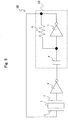
- Fig. 1 is a diagram schematically showing a self-oscillation circuit 9A according to one embodiment of the first aspect of the present invention.
- a exciting means 2 is equipped with a vibrator 1 and connected with the self-oscillation circuit 9A to form an oscillation loop.
- the circuit is activated when a gain of a current/voltage amplifier (alternating current amplifier) 3 in the self-oscillation circuit 9A is large. Only noise is input into the amplifier 3 at the time.
- a current/voltage amplifier alternating current amplifier
- the vibrator 1 is made of a piezoelectric single crystal, for example, as described later.
- the vibrator 1 acts as a frequency filter so that a signal substantially containing a vibration of a natural resonance frequency is output as an arrow "D".
- the signal "D" is input into the amplifier 3.
- the operations are repeated in the oscillation loop to improve the ratio of the signal having a natural resonance frequency, so that the amplitude of the input signal to the amplifier 3 is increased.
- the gain of the amplifier 3 is adjusted so that the loop gain (gain when the signal is circulated once in the oscillation loop) is adjusted at 1. Finally, the loop gain reached 1 without adjusting the gain of the amplifier. At this point, the oscillation of the vibrator is stabilized.
- the stable oscillation of the vibrator is indispensable for measurement of a physical value due to the following reasons. If the amplitude of the driving signal for oscillating the vibrator is not constant, the amplitude of the detection signal output by the vibrator is not also constant to prevent the accurate measurement of the physical value.
- the amplifier 3 is serially connected with a resistor 4 and a CR oscillation circuit 5A.
- the characteristics of the CR oscillation circuit 5A is described referring to Figs. 2(a) and 2(b) .
- the CR oscillation circuit 5A has a condenser 8, an alternating current amplifier 7 and a resistor 6. It is now provided that the rectangular wave has an input wave form broad as shown in "B” in Fig. 2(b) at a position "B” in the CR oscillation circuit 5A.
- the output wave from is sharpened as shown in "A" of Fig. 2(b) and its amplitude is increased at a position "A".
- Such self-oscillation circuit using a CR oscillation circuit is suitable for rapidly activating a vibrator due to the following reasons.
- Fig. 3(a) it is provided that the vibrator 1 is excited using the self-oscillation circuit.
- the signal wave has a wave form of sin wave
- the signal level at the point "a” is gradually increased over time as described above and then stabilized (loop gain reaches 1).
- the amplifier 3 exhibits linear amplification characteristic.
- the signal level at the point "a” may not be substantially increased over time due to the following reasons as shown in Fig. 4 .
- the amplification characteristic of the amplifier has a lower threshold (lower limit) as shown in Fig. 4(b) .
- the signal level cannot be amplified in a short time if the initial level of the signal wave is low.
- Figs. 1 and 2 it is possible to sharpen the wave form of the rectangular wave and to improve the amplitude in the CR oscillation circuit 5A as shown in Fig. 2(b) .
- the signal wave can be easily amplified during the rectangular wave for the driving signal is looped as arrows "C" and "D", by providing the CR oscillation circuit in the self-oscillation circuit 9A, even when the initial level of the signal wave is low.
- the driving vibration of the vibrator can be activated in a short time by utilizing the characteristics of the CR oscillation circuit.
- the CR oscillation circuit is automatically separated from the oscillation from the self-oscillation circuit without switching.
- the present invention is superior in that the driving signal of rectangular wave can be applied on the vibrator in a short time period without the need of the dedicated oscillator and switching mechanism.
- Fig. 5 is a circuit diagram showing a self-oscillating circuit 9B according to the first aspect of the present invention.
- a CR oscillation circuit 5B used in the present example also has a condenser 8, an amplifier 7 and a resistor 6.
- the amplifier 7 and condenser 8 are serially connected in the present example.
- Fig. 6 is a circuit diagram showing a self oscillating circuit 9C according to an embodiment of the second aspect of the present invention.
- a ring oscillator 10 is connected instead of the above CR oscillation circuit. That is, a plurality of amplifiers 10a, 10b and 10c are serially connected with each other to produce the ring oscillator 10.
- the ring oscillator 10 is serially connected with the condenser 8 and connected with the resistor 6 in parallel.
- the characteristics of the ring oscillator 10 is schematically shown in Figs. 7(a) and (b) .
- Rectangular wave at the point "B" in the upstream of the ring oscillator 10 is output at the point "A" as rectangular wave with the phase delayed as arrows.
- the phase of the rectangular wave is made delayed at a predetermined time period in the ring oscillator 10, and the ring oscillator 10 is connected with the self-oscillator 10. It is thus possible to amplify the signal of a specific frequency in the ring oscillator 10.
- Fig. 8 is a circuit diagram showing another self-oscillation circuit 9D according to an embodiment of the first aspect of the present invention.
- the circuit of the present example is substantially same as the self-oscillating circuit 9B of Fig.5 , except that the circuit is ground through a resistor 4 in the present example.
- an accumulator 11 is connected with an accumulator 7 to provide a comparator.
- a standard voltage line is connected to the accumulator 11. The amplitude of the signal in the circuit is judged by the accumulator 11, and, responsive to this, the gain in the amplifier 7 is controlled.
- the self-oscillation circuit has an alternating current amplifier for frequency control and a circuit for controlling amplitude (AGC circuit).
- AGC circuit a circuit for controlling amplitude
- the deviation of the amplitude is prevented to output a signal having a constant value of amplitude.
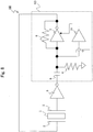
- Fig. 9 is a block diagram schematically showing a control circuit of a vibrator usable in the present invention.
- the control circuit 31 has a driving circuit 32 and a detection circuit 33.
- the driving circuit 32 is provided for exciting a driving vibration part 1a of a vibrator 1.
- the driving circuit 32 has self oscillation circuits 9A, 9B, 9C or 9D and a diagnosis circuit 29.
- a noise is input from an activation circuit to the self-oscillation circuit.
- the noise passes through the driving vibration part 1a of the vibrator and subject to frequency selection, and then input into the alternating current amplifier 3 of the self-oscillation circuit for subsequent amplification as an arrow "D".
- a part of the output signal from the alternating current amplifier 3 is drawn and input to a rectifier to convert the signal to the amplitude value of the signal.
- the signal of amplitude value is input to the CR oscillation circuit or ring oscillator.
- the self-oscillation circuit is connected to the diagnosis circuit 29, and the output of the diagnosis circuit 29 is output through a DIAG terminal to the outside.
- a substantial portion of the noise is cut in the vibrator 1a direct after the activation, so that the output from the rectifier is relatively low.
- the gain in the amplifier is made large so that a loop gain during one oscillation loop is adjusted at 1. Since the output from the rectifier becomes larger over time, the gain in the amplifier is made lower so that the loop gain is adjusted at 1.
- the detection of signals by detection parts 1b and 1c of the vibrator is started. That is, detection signals (alternating current) from the detection parts 1b and 1c of the vibrator are amplified using alternating current amplifiers 21A and 21B. Outputs from the amplifiers 21A and 21B are added by an adder 22.
- a part of a driving signal is derivated and the thus derivated signal is supplied to a phase shifter 23 to obtain to a sifted signal.
- the phase of the shifted signal is different from that of a leakage signal at a predetermined angle, for example, 90 °.
- the shifted signal is input into a phase detector 14 to detect the output signal from the vibrator. As a result, unnecessary leakage signal should be cancelled or at least reduced in the output signal after the phase detection.
- the output signal after the phase detection is input into a low path filter 17 and smoothed and then input into a zero point adjusting circuit 18. The output is drawn to the outside.
- the construction of the vibrator is not particularly limited.
- the Q value of a material for the vibrator may preferably be 3000 or higher, and more preferably be 10000 or higher.
- the material for the vibrator includes a permanent elastic alloy such as elinver and a ferroelectric single crystal (piezoelectric single crystal).
- a permanent elastic alloy such as elinver and a ferroelectric single crystal (piezoelectric single crystal).
- piezoelectric single crystal piezoelectric single crystal
- Such single crystal includes quartz, lithium niobate, lithium tantalate, lithium niobate-lithium tantalate solid solution, lithium borate and langasite.
- a physical value measured according to the present invention is not particularly limited.
- the physical value is included in the present invention as far as the physical value can be detected through a detection circuit.
- Such physical value may preferably be an acceleration, an angular acceleration or an angular velocity applied on a vibrator.
- the measuring system of the present invention may preferably be an inertia censor.
- a vibrator described in Japanese patent publication 11-281372A was used.
- the vibrator had two driving vibration pieces 1a, and two detection vibration pieces 1b and 1c vibrating independently from the driving vibration pieces.
- Noise in a frequency range of 100 to 500 kHz was generated from the activation circuit, and then input into the oscillation loop to activate self-oscillation.
- the delay time of the comparator was 1.0 ⁇ s (500 kHz), the amplitude of output was 2Vp-p, and the width of dead zone voltage was 5 mV.
- the resistance of the resistor 6 was 10 M ⁇ , and the capacity of the condenser 8 was 10 pF (1MHz).
- a time period required for stabilizing the oscillation of the driving signal was about 0.160 seconds.
- the amplitude of the driving signal was 1.1 V and the frequency was 44.1 kHz.
- the present invention provides a method and system suitable for applying a driving signal of rectangular wave on a vibrator to excite a driving vibration in the vibrator.
Landscapes
- Physics & Mathematics (AREA)
- Engineering & Computer Science (AREA)
- General Physics & Mathematics (AREA)
- Radar, Positioning & Navigation (AREA)
- Remote Sensing (AREA)
- Gyroscopes (AREA)
Claims (8)
- Verfahren zur Anregung einer Ansteuerungsschwingung in einem Schwinger (1), um ein Detektionssignal auszugeben, das auf Grundlage der Ansteuerungsschwingung und eines physikalischen Werts erzeugt wird, und um den physikalischen Wert auf Grundlage des Detektionssignals zu messen, wobei der physikalische Wert eine Winkelgeschwindigkeit ist, die am Schwinger anliegt;
worin die Ansteuerungsschwingung unter Verwendung eines Schaltkreises (9A, 9B) zur selbsterregten Schwingung angeregt wird,
dadurch gekennzeichnet, dass:der Schaltkreis Folgendes umfasst:(i) einen Strom-Spannungsverstärker (3) zum Verstärken eines vom Schwinger (1) ausgegebenen Signals,(ii) gegebenenfalls einen ersten Widerstand (4), der mit dem Strom-Spannungsverstärker (3) in Reihe geschaltet ist, sowie(iii) einen CR-Oszillator (5A, 5B), der mit dem Strom-Spannungsverstärker (3) in Reihe geschaltet ist, wobei der CR-Oszillator (5A, 5B) einen Kondensator (8), einen Wechselstromverstärker (7) und einen zweiten Widerstand (6) umfasst,worin der Schwinger (1), der erste Widerstand (4) - sofern bereitgestellt - und der CR-Oszillator (5A, 5B) einen Eigenschwingkreis bilden; unddas Verfahren folgende Schritte umfasst:Anlegen eines Aktivierungssignals (A) mit einer rechteckigen Wellenform vom CR-Oszillator (5A, 5B) an den Schwinger (1), sodass ein Signal mit der Form einer Sinuswelle angeregt und in den Eigenschwingkreis eingekoppelt wird, um die Schwingung des Schwingers (1) zu stabilisieren;worin ein von dem Schwinger (1) ausgegebenes Signal von dem Strom-Spannungsverstärker (3) verstärkt und in den Eigenschwingkreis eingekoppelt wird, bis sich die Schwingung des Schwingers (1) stabilisiert hat. - Verfahren nach Anspruch 1, worin ein Signal aus dem CR-Oszillator (5A, 5B) automatisch ohne Schalten vom Eigenschwingkreis getrennt wird, wenn der Pegel des Ansteuerungssignals erhöht ist.
- System zum Anregen einer Ansteuerungsschwingung in einem Schwinger (1), um ein Detektionssignal auszugeben, das auf Grundlage der Ansteuerungsschwingung und eines physikalischen Werts erzeugt wird, und um den physikalischen Wert auf Grundlage des Detektionssignals zu messen, wobei der physikalische Wert eine Winkelgeschwindigkeit ist, die am Schwinger anliegt;
wobei das System einen Schaltkreis (9A, 9B) zur selbsterregten Schwingung umfasst, um die Ansteuerungsschwingung zu erregen,
dadurch gekennzeichnet, dass:der Schaltkreis Folgendes umfasst:(i) einen Strom-Spannungsverstärker (3) zum Verstärken eines vom Schwinger (1) ausgegebenen Signals,(ii) gegebenenfalls einen ersten Widerstand (4), der mit dem Strom-Spannungsverstärker (3) in Reihe geschaltet ist, sowie(iii) einen CR-Oszillator (5A, 5B), der mit dem Strom-Spannungsverstärker (3) in Reihe geschaltet ist, wobei der CR-Oszillator (5A, 5B) einen Kondensator (8), einen Wechselstromverstärker (7) und einen zweiten Widerstand (6) umfasst,worin der Schwinger (1), der erste Widerstand (4) - sofern bereitgestellt - und der CR-Oszillator (5A, 5B) einen Eigenschwingkreis bilden; undder CR-Oszillator (5A, 5B) angeordnet ist, um ein Aktivierungssignal mit einer rechteckigen Wellenform an den Schwinger (1) anzulegen, sodass ein Signal, das die Form einer Sinuswelle aufweist, angeregt und in den Eigenschwingkreis eingekoppelt wird, um die Schwingung des Schwingers (1) zu stabilisieren;worin der Strom-Spannungsverstärker (3) angeordnet ist, um ein vom Schwinger (1) ausgegebenes Signal zu verstärken, sodass das Signal in den Eigenschwingkreis eingekoppelt wird, bis sich die Schwingung des Schwingers (1) stabilisiert hat. - System nach Anspruch 3, worin der Schaltkreis (9A, 9B) so angeordnet ist, dass ein Signal vom CR-Oszillator (5A, 5B) automatisch ohne Schalten vom Eigenschwingkreis getrennt wird, wenn der Pegel des Ansteuerungssignals erhöht ist.
- Verfahren zur Anregung einer Ansteuerungsschwingung in einem Schwinger (1), um ein Detektionssignal auszugeben, das auf Grundlage der Ansteuerungsschwingung und eines physikalischen Werts erzeugt wird, und um den physikalischen Wert auf Grundlage des Detektionssignals zu messen, wobei der physikalische Wert eine Winkelgeschwindigkeit ist, die am Schwinger anliegt;
worin die Ansteuerungsschwingung unter Verwendung eines Schaltkreises (9C) zur selbsterregten Schwingung angeregt wird,
dadurch gekennzeichnet, dass:der Schaltkreis einen Strom-Spannungsverstärker (3) zum Verstärken eines vom Schwinger (1) ausgegebenen Signals, einen Kondensator (8), der mit dem Strom-Spannungsverstärker (3) in Reihe geschaltet ist, einen Ringoszillator (10), der mit dem Kondensator (8) in Reihe geschaltet ist, sowie einen Widerstand (6), der mit dem Ringoszillator (10) parallelgeschaltet ist, umfasst, worin der Schwinger (1), der Strom-Spannungsverstärker (3), der Kondensator (8) und der Ringoszillator (10) einen Eigenschwingkreis bilden; unddas Verfahren folgende Schritte umfasst:Anlegen eines Aktivierungssignals mit einer rechteckigen Wellenform (A) vom Ringoszillator (10) an den Schwinger (1), sodass ein Signal mit der Form einer Sinuswelle angeregt und in den Eigenschwingkreis eingekoppelt wird, um die Schwingung des Schwingers zu stabilisieren;worin ein vom Schwinger (1) ausgegebenes Signal vom Strom-Spannungsverstärker (3) verstärkt wird und in den Eigenschwingkreis eingekoppelt wird, bis sich die Schwingung des Schwingers (1) stabilisiert hat. - Verfahren nach Anspruch 5, worin ein Signal vom Ringoszillator (10) automatisch ohne Schalten vom Eigenschwingkreis getrennt wird, wenn sich der Pegel des Ansteuerungssignals erhöht.
- System zur Anregung einer Ansteuerungsschwingung in einem Schwinger (1), um ein Detektionssignal auszugeben, das auf Grundlage der Ansteuerungsschwingung und eines physikalischen Werts erzeugt wird, und um den physikalischen Wert auf Grundlage des Detektionssignals zu messen, wobei der physikalische Wert eine Winkelgeschwindigkeit ist, die am Schwinger anliegt;
wobei das System einen Schaltkreis (9C) zur selbsterregten Schwingung umfasst,
dadurch gekennzeichnet, dass:der Schaltkreis einen Strom-Spannungsverstärker (3) zum Verstärken eines vom Schwinger (1) ausgegebenen Signals, einen Kondensator (8), der mit dem Strom-Spannungsverstärker (3) in Reihe geschaltet ist, einen Ringoszillator (10), der mit dem Kondensator (8) in Reihe geschaltet ist, und einen Widerstand (6), der mit dem Ringoszillator parallelgeschaltet ist, umfasst, worin der Schwinger (1), der Strom-Spannungsverstärker (3), der Kondensator und der Ringoszillator (10) einen Eigenschwingkreis bilden; undder Ringoszillator angeordnet ist, um ein Aktivierungssignal mit einer rechteckigen Wellenform (A) an den Schwinger (1) anzulegen, sodass ein Signal mit der Form einer Sinuswelle angeregt wird und in den Eigenschwingkreis eingekoppelt wird, um die Schwingung des Schwingers zu stabilisieren;worin der Strom-Spannungsverstärker (3) angeordnet ist, um ein vom Schwinger (1) ausgegebenes Signal zu verstärken, sodass das Signal in den Eigenschwingkreis eingekoppelt wird, bis sich die Schwingung des Schwingers (1) stabilisiert hat. - System nach Anspruch 7, worin der Schaltkreis (9C) so angeordnet ist, dass ein Signal vom Ringoszillator (10) automatisch ohne Schalten vom Eigenschwingkreis getrennt wird, wenn sich der Pegel des Ansteuerungssignals erhöht.
Applications Claiming Priority (2)
| Application Number | Priority Date | Filing Date | Title |
|---|---|---|---|
| JP2003077155A JP4336946B2 (ja) | 2003-03-20 | 2003-03-20 | 回転角速度の測定方法および装置 |
| JP2003077155 | 2003-03-20 |
Publications (2)
| Publication Number | Publication Date |
|---|---|
| EP1460380A1 EP1460380A1 (de) | 2004-09-22 |
| EP1460380B1 true EP1460380B1 (de) | 2017-08-23 |
Family
ID=32821371
Family Applications (1)
| Application Number | Title | Priority Date | Filing Date |
|---|---|---|---|
| EP04251600.5A Expired - Lifetime EP1460380B1 (de) | 2003-03-20 | 2004-03-19 | Verfahren und System zur Anregung einer Schwingung eines Vibrators |
Country Status (4)
| Country | Link |
|---|---|
| US (1) | US7089793B2 (de) |
| EP (1) | EP1460380B1 (de) |
| JP (1) | JP4336946B2 (de) |
| CN (1) | CN100489454C (de) |
Families Citing this family (44)
| Publication number | Priority date | Publication date | Assignee | Title |
|---|---|---|---|---|
| US7370531B2 (en) * | 2004-01-20 | 2008-05-13 | Ngk Insulators, Ltd. | Detection circuits, detection method and systems of measuring physical quantities |
| US7849744B2 (en) | 2006-08-02 | 2010-12-14 | Seiko Epson Corporation | Driving device, physical quantity measurement device, and electronic instrument |
| JP4930253B2 (ja) * | 2006-08-02 | 2012-05-16 | セイコーエプソン株式会社 | 駆動装置、物理量測定装置及び電子機器 |
| JP2008089577A (ja) | 2006-09-08 | 2008-04-17 | Seiko Epson Corp | 駆動装置、物理量測定装置及び電子機器 |
| JP5034808B2 (ja) | 2006-10-17 | 2012-09-26 | セイコーエプソン株式会社 | 駆動装置、物理量測定装置及び電子機器 |
| JP5200491B2 (ja) * | 2006-11-06 | 2013-06-05 | セイコーエプソン株式会社 | 駆動装置、物理量測定装置及び電子機器 |
| US7895894B2 (en) | 2006-11-06 | 2011-03-01 | Seiko Epson Corporation | Driver device, physical quantity measuring device, and electronic instrument |
| JP5136016B2 (ja) | 2006-11-27 | 2013-02-06 | セイコーエプソン株式会社 | 駆動装置、物理量測定装置及び電子機器 |
| US8026771B2 (en) | 2006-11-27 | 2011-09-27 | Seiko Epson Corporation | Driver device, physical quantity measuring device, and electronic instrument |
| US7692506B2 (en) | 2007-08-01 | 2010-04-06 | Seiko Epson Corporation | Oscillation driver device, physical quantity measuring device, and electronic instrument |
| JP5451396B2 (ja) * | 2007-09-25 | 2014-03-26 | ローム株式会社 | 角速度検出装置 |
| US8265308B2 (en) | 2007-12-07 | 2012-09-11 | Motorola Mobility Llc | Apparatus including two housings and a piezoelectric transducer |
| US8395587B2 (en) * | 2007-12-21 | 2013-03-12 | Motorola Mobility Llc | Haptic response apparatus for an electronic device |
| JP2010190766A (ja) | 2009-02-19 | 2010-09-02 | Seiko Epson Corp | 発振駆動装置、物理量測定装置及び電子機器 |
| US8739626B2 (en) | 2009-08-04 | 2014-06-03 | Fairchild Semiconductor Corporation | Micromachined inertial sensor devices |
| GB201005875D0 (en) | 2010-04-08 | 2010-05-26 | Silicon Sensing Systems Ltd | Sensors |
| DE112011103124T5 (de) | 2010-09-18 | 2013-12-19 | Fairchild Semiconductor Corporation | Biegelager zum Verringern von Quadratur für mitschwingende mikromechanische Vorrichtungen |
| EP2616389B1 (de) | 2010-09-18 | 2017-04-05 | Fairchild Semiconductor Corporation | Mehrchip-mems-verpackung |
| EP2616772B1 (de) | 2010-09-18 | 2016-06-22 | Fairchild Semiconductor Corporation | Mikroverarbeitetes monolithisches 3-achsen-gyroskop mit einzelantrieb |
| US9278846B2 (en) | 2010-09-18 | 2016-03-08 | Fairchild Semiconductor Corporation | Micromachined monolithic 6-axis inertial sensor |
| US9856132B2 (en) | 2010-09-18 | 2018-01-02 | Fairchild Semiconductor Corporation | Sealed packaging for microelectromechanical systems |
| US8813564B2 (en) | 2010-09-18 | 2014-08-26 | Fairchild Semiconductor Corporation | MEMS multi-axis gyroscope with central suspension and gimbal structure |
| KR101332701B1 (ko) | 2010-09-20 | 2013-11-25 | 페어차일드 세미컨덕터 코포레이션 | 기준 커패시터를 포함하는 미소 전자기계 압력 센서 |
| KR101311966B1 (ko) | 2010-09-20 | 2013-10-14 | 페어차일드 세미컨덕터 코포레이션 | 감소된 션트 커패시턴스를 갖는 관통 실리콘 비아 |
| US9062972B2 (en) | 2012-01-31 | 2015-06-23 | Fairchild Semiconductor Corporation | MEMS multi-axis accelerometer electrode structure |
| US8978475B2 (en) | 2012-02-01 | 2015-03-17 | Fairchild Semiconductor Corporation | MEMS proof mass with split z-axis portions |
| JP5729323B2 (ja) * | 2012-02-09 | 2015-06-03 | 株式会社デンソー | 自励共振回路 |
| CN103368562B (zh) * | 2012-04-03 | 2016-03-23 | 快捷半导体(苏州)有限公司 | 准确的90度相位移相器 |
| US8754694B2 (en) * | 2012-04-03 | 2014-06-17 | Fairchild Semiconductor Corporation | Accurate ninety-degree phase shifter |
| US9488693B2 (en) | 2012-04-04 | 2016-11-08 | Fairchild Semiconductor Corporation | Self test of MEMS accelerometer with ASICS integrated capacitors |
| US8742964B2 (en) | 2012-04-04 | 2014-06-03 | Fairchild Semiconductor Corporation | Noise reduction method with chopping for a merged MEMS accelerometer sensor |
| KR102058489B1 (ko) | 2012-04-05 | 2019-12-23 | 페어차일드 세미컨덕터 코포레이션 | 멤스 장치 프론트 엔드 전하 증폭기 |
| EP2647952B1 (de) | 2012-04-05 | 2017-11-15 | Fairchild Semiconductor Corporation | Automatische Verstärkungsregelungsschleife einer MEMS-Vorrichtung für mechanischen Amplitudenantrieb |
| US9069006B2 (en) | 2012-04-05 | 2015-06-30 | Fairchild Semiconductor Corporation | Self test of MEMS gyroscope with ASICs integrated capacitors |
| EP2647955B8 (de) | 2012-04-05 | 2018-12-19 | Fairchild Semiconductor Corporation | MEMS-Vorrichtung mit Quadraturphasenverschiebungsauslöschung |
| KR101999745B1 (ko) | 2012-04-12 | 2019-10-01 | 페어차일드 세미컨덕터 코포레이션 | 미세 전자 기계 시스템 구동기 |
| US9625272B2 (en) | 2012-04-12 | 2017-04-18 | Fairchild Semiconductor Corporation | MEMS quadrature cancellation and signal demodulation |
| DE102013014881B4 (de) | 2012-09-12 | 2023-05-04 | Fairchild Semiconductor Corporation | Verbesserte Silizium-Durchkontaktierung mit einer Füllung aus mehreren Materialien |
| KR20140123259A (ko) * | 2013-04-12 | 2014-10-22 | 삼성전기주식회사 | 자가발진 회로 및 그 방법 |
| JP6032243B2 (ja) * | 2014-05-23 | 2016-11-24 | 横河電機株式会社 | 電流電圧変換回路及び自励発振回路 |
| JP6570428B2 (ja) | 2015-11-09 | 2019-09-04 | セイコーエプソン株式会社 | 物理量検出装置、電子機器および移動体 |
| CN107104637B (zh) * | 2016-02-19 | 2021-03-12 | 横河电机株式会社 | 自振荡电路 |
| CN110470291B (zh) * | 2019-09-04 | 2023-11-24 | 中国海洋大学 | 一种mems谐振式陀螺仪接口电路与测控系统 |
| CN113296397B (zh) * | 2021-07-27 | 2021-10-29 | 中国人民解放军国防科技大学 | 基于参数激励的陀螺仪快速起振的方法和装置 |
Citations (2)
| Publication number | Priority date | Publication date | Assignee | Title |
|---|---|---|---|---|
| JPH07131248A (ja) * | 1993-10-28 | 1995-05-19 | Nippon Precision Circuits Kk | 発振用集積回路 |
| JP2003032039A (ja) * | 2001-07-16 | 2003-01-31 | Toyo Commun Equip Co Ltd | 圧電発振回路 |
Family Cites Families (17)
| Publication number | Priority date | Publication date | Assignee | Title |
|---|---|---|---|---|
| US3805592A (en) * | 1970-08-20 | 1974-04-23 | Itt | Densitometer |
| US4020330A (en) * | 1976-05-03 | 1977-04-26 | International Telephone And Telegraph Corporation | Densitometer |
| US5365768A (en) * | 1989-07-20 | 1994-11-22 | Hitachi, Ltd. | Sensor |
| JPH0933262A (ja) * | 1995-07-25 | 1997-02-07 | Nikon Corp | 励振駆動回路及び方法並びにこれを用いた圧電振動角速度計 |
| US5630216A (en) * | 1994-09-06 | 1997-05-13 | The Regents Of The University Of California | Micropower RF transponder with superregenerative receiver and RF receiver with sampling mixer |
| JP3739492B2 (ja) * | 1996-02-21 | 2006-01-25 | 富士通株式会社 | 音叉型圧電振動ジャイロ |
| JPH10221083A (ja) * | 1997-02-05 | 1998-08-21 | Murata Mfg Co Ltd | 振動型ジャイロ装置 |
| JP3718786B2 (ja) * | 1997-02-17 | 2005-11-24 | 日本航空電子工業株式会社 | 振動ジャイロ |
| JP3697847B2 (ja) * | 1997-08-21 | 2005-09-21 | ソニー株式会社 | 電圧制御発振回路 |
| JP3999377B2 (ja) | 1997-11-04 | 2007-10-31 | 日本碍子株式会社 | 振動子、振動型ジャイロスコープ、直線加速度計および回転角速度の測定方法 |
| DE19811025B4 (de) | 1998-03-13 | 2004-04-15 | Hahn-Schickard-Gesellschaft für angewandte Forschung e.V. | Mechanischer Oszillator und Verfahren zum Erzeugen einer mechanischen Schwingung |
| US6397656B1 (en) * | 1999-01-25 | 2002-06-04 | Yamatake Corporation | System and method for detecting liquid serving as object to be detected in vessel using ultrasonic sensor |
| JP4361174B2 (ja) * | 1999-09-16 | 2009-11-11 | セイコーエプソン株式会社 | 振動型ジャイロスコープ |
| DE10046958B4 (de) * | 1999-09-27 | 2009-01-02 | Denso Corp., Kariya-shi | Kapazitive Vorrichtung zum Erfassen einer physikalischen Grösse |
| US6445195B1 (en) * | 2000-08-02 | 2002-09-03 | The Charles Stark Draper Laboratory, Inc. | Drive feedthrough nulling system |
| US6510737B1 (en) | 2000-09-15 | 2003-01-28 | Bei Technologies, Inc. | Inertial rate sensor and method with improved tuning fork drive |
| JP4449262B2 (ja) | 2001-07-09 | 2010-04-14 | セイコーエプソン株式会社 | 振動子を用いた測定方法、測定装置および振動子の駆動装置 |
-
2003
- 2003-03-20 JP JP2003077155A patent/JP4336946B2/ja not_active Expired - Lifetime
-
2004
- 2004-03-17 US US10/803,176 patent/US7089793B2/en active Active
- 2004-03-19 CN CNB2004100304361A patent/CN100489454C/zh not_active Expired - Lifetime
- 2004-03-19 EP EP04251600.5A patent/EP1460380B1/de not_active Expired - Lifetime
Patent Citations (2)
| Publication number | Priority date | Publication date | Assignee | Title |
|---|---|---|---|---|
| JPH07131248A (ja) * | 1993-10-28 | 1995-05-19 | Nippon Precision Circuits Kk | 発振用集積回路 |
| JP2003032039A (ja) * | 2001-07-16 | 2003-01-31 | Toyo Commun Equip Co Ltd | 圧電発振回路 |
Also Published As
| Publication number | Publication date |
|---|---|
| CN1532524A (zh) | 2004-09-29 |
| US7089793B2 (en) | 2006-08-15 |
| JP4336946B2 (ja) | 2009-09-30 |
| EP1460380A1 (de) | 2004-09-22 |
| JP2004286503A (ja) | 2004-10-14 |
| CN100489454C (zh) | 2009-05-20 |
| US20040182184A1 (en) | 2004-09-23 |
Similar Documents
| Publication | Publication Date | Title |
|---|---|---|
| EP1460380B1 (de) | Verfahren und System zur Anregung einer Schwingung eines Vibrators | |
| US7370531B2 (en) | Detection circuits, detection method and systems of measuring physical quantities | |
| US8618889B2 (en) | Oscillation drive device, physical quantity measurement device and electronic apparatus | |
| US6510737B1 (en) | Inertial rate sensor and method with improved tuning fork drive | |
| US4056761A (en) | Sonic transducer and drive circuit | |
| EP1707919B1 (de) | Einrichtung zur messung physikalischer grössen | |
| US20090078045A1 (en) | Driver device, physical quantity measuring device, and electronic instrument | |
| JP4573017B2 (ja) | 振動子を用いた検出方法および検出装置 | |
| JP4449262B2 (ja) | 振動子を用いた測定方法、測定装置および振動子の駆動装置 | |
| WO2000016043A1 (fr) | Capteur de vitesse angulaire | |
| JP3985893B2 (ja) | 物理量の測定装置 | |
| JP2000028364A (ja) | 角速度センサ装置及びその駆動方法 | |
| JP2008089572A (ja) | 駆動装置、物理量測定装置及び電子機器 | |
| US7140251B2 (en) | Devices for measuring physical values and vibrators | |
| JP4930253B2 (ja) | 駆動装置、物理量測定装置及び電子機器 | |
| US11118906B2 (en) | Oscillator circuit including oscillator | |
| JP4337008B2 (ja) | 回転角速度の測定方法および装置 | |
| JP2000292172A (ja) | 圧電振動子の駆動および検出装置 | |
| JP2005345109A (ja) | 物理量測定方法および装置 | |
| JPH09292231A (ja) | 振動ジャイロ | |
| JP3227975B2 (ja) | 振動検出回路 | |
| JPH1151657A (ja) | 圧電振動式角速度センサの励振回路 | |
| JPH09292234A (ja) | 振動ジャイロ | |
| JPH09292232A (ja) | 振動ジャイロ |
Legal Events
| Date | Code | Title | Description |
|---|---|---|---|
| PUAI | Public reference made under article 153(3) epc to a published international application that has entered the european phase |
Free format text: ORIGINAL CODE: 0009012 |
|
| AK | Designated contracting states |
Kind code of ref document: A1 Designated state(s): AT BE BG CH CY CZ DE DK EE ES FI FR GB GR HU IE IT LI LU MC NL PL PT RO SE SI SK TR |
|
| AX | Request for extension of the european patent |
Extension state: AL LT LV MK |
|
| 17P | Request for examination filed |
Effective date: 20041220 |
|
| AKX | Designation fees paid |
Designated state(s): DE FR GB |
|
| RAP1 | Party data changed (applicant data changed or rights of an application transferred) |
Owner name: SEIKO EPSON CORPORATION |
|
| 17Q | First examination report despatched |
Effective date: 20090527 |
|
| GRAP | Despatch of communication of intention to grant a patent |
Free format text: ORIGINAL CODE: EPIDOSNIGR1 |
|
| INTG | Intention to grant announced |
Effective date: 20170228 |
|
| RIN1 | Information on inventor provided before grant (corrected) |
Inventor name: KOBAYASHI YOSHIHIRO, Inventor name: YOKOI SHOJI, |
|
| GRAS | Grant fee paid |
Free format text: ORIGINAL CODE: EPIDOSNIGR3 |
|
| GRAA | (expected) grant |
Free format text: ORIGINAL CODE: 0009210 |
|
| AK | Designated contracting states |
Kind code of ref document: B1 Designated state(s): DE FR GB |
|
| REG | Reference to a national code |
Ref country code: GB Ref legal event code: FG4D |
|
| REG | Reference to a national code |
Ref country code: DE Ref legal event code: R096 Ref document number: 602004051693 Country of ref document: DE |
|
| REG | Reference to a national code |
Ref country code: FR Ref legal event code: PLFP Year of fee payment: 15 |
|
| REG | Reference to a national code |
Ref country code: DE Ref legal event code: R097 Ref document number: 602004051693 Country of ref document: DE |
|
| PLBE | No opposition filed within time limit |
Free format text: ORIGINAL CODE: 0009261 |
|
| STAA | Information on the status of an ep patent application or granted ep patent |
Free format text: STATUS: NO OPPOSITION FILED WITHIN TIME LIMIT |
|
| 26N | No opposition filed |
Effective date: 20180524 |
|
| PGFP | Annual fee paid to national office [announced via postgrant information from national office to epo] |
Ref country code: ES Payment date: 20190301 Year of fee payment: 18 |
|
| PGFP | Annual fee paid to national office [announced via postgrant information from national office to epo] |
Ref country code: FR Payment date: 20190213 Year of fee payment: 16 |
|
| PG25 | Lapsed in a contracting state [announced via postgrant information from national office to epo] |
Ref country code: FR Free format text: LAPSE BECAUSE OF NON-PAYMENT OF DUE FEES Effective date: 20200331 |
|
| GBPC | Gb: european patent ceased through non-payment of renewal fee |
Effective date: 20200319 |
|
| PG25 | Lapsed in a contracting state [announced via postgrant information from national office to epo] |
Ref country code: GB Free format text: LAPSE BECAUSE OF NON-PAYMENT OF DUE FEES Effective date: 20200319 |
|
| PGFP | Annual fee paid to national office [announced via postgrant information from national office to epo] |
Ref country code: DE Payment date: 20230131 Year of fee payment: 20 |
|
| REG | Reference to a national code |
Ref country code: DE Ref legal event code: R071 Ref document number: 602004051693 Country of ref document: DE |