EP1453345A1 - Systeme de traitement d'informations, dispositif et procede de fourniture de services, dispositif et procede de traitement d'informations, support d'enregistrement et programme - Google Patents
Systeme de traitement d'informations, dispositif et procede de fourniture de services, dispositif et procede de traitement d'informations, support d'enregistrement et programme Download PDFInfo
- Publication number
- EP1453345A1 EP1453345A1 EP03751370A EP03751370A EP1453345A1 EP 1453345 A1 EP1453345 A1 EP 1453345A1 EP 03751370 A EP03751370 A EP 03751370A EP 03751370 A EP03751370 A EP 03751370A EP 1453345 A1 EP1453345 A1 EP 1453345A1
- Authority
- EP
- European Patent Office
- Prior art keywords
- user
- information processing
- virtual space
- service
- virtual
- Prior art date
- Legal status (The legal status is an assumption and is not a legal conclusion. Google has not performed a legal analysis and makes no representation as to the accuracy of the status listed.)
- Withdrawn
Links
- 230000010365 information processing Effects 0.000 title claims abstract description 141
- 238000000034 method Methods 0.000 title claims abstract description 23
- 238000004891 communication Methods 0.000 claims description 112
- 230000004044 response Effects 0.000 claims description 98
- 230000008569 process Effects 0.000 claims description 2
- 238000003672 processing method Methods 0.000 claims description 2
- 238000012545 processing Methods 0.000 description 150
- 230000001360 synchronised effect Effects 0.000 description 55
- 238000012546 transfer Methods 0.000 description 28
- 230000005540 biological transmission Effects 0.000 description 15
- 238000012217 deletion Methods 0.000 description 9
- 230000037430 deletion Effects 0.000 description 9
- 238000012795 verification Methods 0.000 description 9
- 230000008859 change Effects 0.000 description 6
- 239000003795 chemical substances by application Substances 0.000 description 4
- 238000010586 diagram Methods 0.000 description 4
- 230000006870 function Effects 0.000 description 4
- 238000012790 confirmation Methods 0.000 description 3
- 238000003825 pressing Methods 0.000 description 3
- 239000004065 semiconductor Substances 0.000 description 3
- 230000009471 action Effects 0.000 description 2
- 230000004397 blinking Effects 0.000 description 2
- 239000000463 material Substances 0.000 description 2
- 239000010813 municipal solid waste Substances 0.000 description 2
- 230000003287 optical effect Effects 0.000 description 2
- 230000036962 time dependent Effects 0.000 description 2
- 230000004308 accommodation Effects 0.000 description 1
- 238000013461 design Methods 0.000 description 1
- 238000005516 engineering process Methods 0.000 description 1
- 230000003993 interaction Effects 0.000 description 1
- 239000004973 liquid crystal related substance Substances 0.000 description 1
- 230000007246 mechanism Effects 0.000 description 1
- 238000012360 testing method Methods 0.000 description 1
- 238000012549 training Methods 0.000 description 1
Images


Classifications
-
- H—ELECTRICITY
- H04—ELECTRIC COMMUNICATION TECHNIQUE
- H04L—TRANSMISSION OF DIGITAL INFORMATION, e.g. TELEGRAPHIC COMMUNICATION
- H04L12/00—Data switching networks
- H04L12/02—Details
- H04L12/12—Arrangements for remote connection or disconnection of substations or of equipment thereof
-
- H—ELECTRICITY
- H04—ELECTRIC COMMUNICATION TECHNIQUE
- H04L—TRANSMISSION OF DIGITAL INFORMATION, e.g. TELEGRAPHIC COMMUNICATION
- H04L12/00—Data switching networks
- H04L12/28—Data switching networks characterised by path configuration, e.g. LAN [Local Area Networks] or WAN [Wide Area Networks]
- H04L12/2803—Home automation networks
- H04L12/2816—Controlling appliance services of a home automation network by calling their functionalities
- H04L12/2818—Controlling appliance services of a home automation network by calling their functionalities from a device located outside both the home and the home network
-
- H—ELECTRICITY
- H04—ELECTRIC COMMUNICATION TECHNIQUE
- H04L—TRANSMISSION OF DIGITAL INFORMATION, e.g. TELEGRAPHIC COMMUNICATION
- H04L12/00—Data switching networks
- H04L12/02—Details
- H04L12/16—Arrangements for providing special services to substations
-
- H—ELECTRICITY
- H04—ELECTRIC COMMUNICATION TECHNIQUE
- H04L—TRANSMISSION OF DIGITAL INFORMATION, e.g. TELEGRAPHIC COMMUNICATION
- H04L12/00—Data switching networks
- H04L12/28—Data switching networks characterised by path configuration, e.g. LAN [Local Area Networks] or WAN [Wide Area Networks]
-
- H—ELECTRICITY
- H04—ELECTRIC COMMUNICATION TECHNIQUE
- H04L—TRANSMISSION OF DIGITAL INFORMATION, e.g. TELEGRAPHIC COMMUNICATION
- H04L12/00—Data switching networks
- H04L12/28—Data switching networks characterised by path configuration, e.g. LAN [Local Area Networks] or WAN [Wide Area Networks]
- H04L12/2803—Home automation networks
- H04L12/2816—Controlling appliance services of a home automation network by calling their functionalities
- H04L12/282—Controlling appliance services of a home automation network by calling their functionalities based on user interaction within the home
-
- H—ELECTRICITY
- H04—ELECTRIC COMMUNICATION TECHNIQUE
- H04Q—SELECTING
- H04Q9/00—Arrangements in telecontrol or telemetry systems for selectively calling a substation from a main station, in which substation desired apparatus is selected for applying a control signal thereto or for obtaining measured values therefrom
-
- H—ELECTRICITY
- H04—ELECTRIC COMMUNICATION TECHNIQUE
- H04L—TRANSMISSION OF DIGITAL INFORMATION, e.g. TELEGRAPHIC COMMUNICATION
- H04L12/00—Data switching networks
- H04L12/28—Data switching networks characterised by path configuration, e.g. LAN [Local Area Networks] or WAN [Wide Area Networks]
- H04L12/2803—Home automation networks
- H04L2012/284—Home automation networks characterised by the type of medium used
- H04L2012/2841—Wireless
-
- H—ELECTRICITY
- H04—ELECTRIC COMMUNICATION TECHNIQUE
- H04L—TRANSMISSION OF DIGITAL INFORMATION, e.g. TELEGRAPHIC COMMUNICATION
- H04L12/00—Data switching networks
- H04L12/28—Data switching networks characterised by path configuration, e.g. LAN [Local Area Networks] or WAN [Wide Area Networks]
- H04L12/2803—Home automation networks
- H04L2012/284—Home automation networks characterised by the type of medium used
- H04L2012/2845—Telephone line
-
- H—ELECTRICITY
- H04—ELECTRIC COMMUNICATION TECHNIQUE
- H04L—TRANSMISSION OF DIGITAL INFORMATION, e.g. TELEGRAPHIC COMMUNICATION
- H04L12/00—Data switching networks
- H04L12/28—Data switching networks characterised by path configuration, e.g. LAN [Local Area Networks] or WAN [Wide Area Networks]
- H04L12/2803—Home automation networks
- H04L2012/2847—Home automation networks characterised by the type of home appliance used
- H04L2012/2849—Audio/video appliances
-
- H—ELECTRICITY
- H04—ELECTRIC COMMUNICATION TECHNIQUE
- H04L—TRANSMISSION OF DIGITAL INFORMATION, e.g. TELEGRAPHIC COMMUNICATION
- H04L12/00—Data switching networks
- H04L12/28—Data switching networks characterised by path configuration, e.g. LAN [Local Area Networks] or WAN [Wide Area Networks]
- H04L12/2803—Home automation networks
- H04L2012/2847—Home automation networks characterised by the type of home appliance used
- H04L2012/285—Generic home appliances, e.g. refrigerators
Definitions
- the present invention relates generally to an information processing system, a service providing apparatus and method, an information processing apparatus and method, a recording medium, and a program and, more particularly, to an information processing system, a service providing apparatus and method, an information processing apparatus and method, a recording medium, and a program that are suitably for use in remotely controlling real devices by operating icons in a virtual space.
- Japanese Patent laid-open No. 2002-44765 discloses a system controlling, via the Internet, the electrical household appliances connected to a home network.
- Japanese Patent No. 3016350 discloses an application program for personal computers using an agent for the interface for the remote control of electrical household appliances.
- UPnP For the programs for remotely controlling electrical household appliances by using personal computers via a network, UPnP, Jini, and HAVi are known for example. These programs are middleware, and the user interface, which is operated by users for controlling their electrical household appliances, depends on other software programs using the middleware such as UPnP.
- the related-art software programs for realizing user interfaces for the remote control of electrical household appliances have only the functions of controlling electrical household appliances, namely, practicality, in many cases. Therefore, these related-art software programs present a problem that they cannot satisfy the needs of users who demand not only practicality but also amusement on the software programs of their personal computers.
- the related-art technologies of forming communication in a virtual spaces also presents a problem of the lack of close communication between users because the forming of communication is achieved by users' entering public, not private, spaces.
- GUI Graphic User Interface
- an information processing system having a service providing apparatus including providing means for providing, to each of the plurality of information processing apparatuses, a service of a private virtual space in which a mascot is arranged; storage means for storing a group to which a user of each of the plurality of information processing apparatuses belongs; sharing means for sharing a service of a private virtual space provided for the information processing apparatus used by the user, the virtual space containing a mascot dedicated to an other user belonging to the group, with the information processing apparatus used by the other user belonging to the group; and relay means for relaying data realtime between the plurality of information processing apparatuses used by the users belonging to the group; each of the plurality of information processing apparatuses including request means for requesting the participation of a mascot of said information processing apparatus into a private space provided for an other information processing apparatus; display control means for controlling the displaying of the virtual space provided by the service providing apparatus in response to the request; and communication means for communicating data realtime with the other information processing
- the above-mentioned storage means of the service providing apparatus stores the group to which the user belongs, by use of identification information of the user or identification information of the information processing apparatus.
- the above-mentioned storage means of the service providing apparatus stores the group to which the user belongs for each of the private virtual spaces provided for the user and the other user.
- the above-mentioned data are text data.
- the above-mentioned data are image data.
- the above-mentioned information processing apparatus further includes reproduction means for reproducing stream data received via the network; and notification means for notifying the other information processing apparatus that the reproduction means has started the reproduction of the stream data.
- the above-mentioned reproduction means if notified by the other information processing apparatus that the reproduction of the stream has started, receives the stream data distributed via the network and reproduces the stream data.
- the above-mentioned information processing apparatus further includes control means for controlling a really existing electronic device via the network by operating an icon corresponding to an electronic device arranged in the virtual space.
- a service providing apparatus including providing means for providing a service of a private virtual space in which a mascot is arranged to each of the plurality of information processing apparatuses; storage means for storing a group to which a user of each of the plurality of information processing apparatuses belongs; sharing means for sharing a service of a private virtual space provided for the information processing apparatus used by the user, the virtual space containing a mascot dedicated to an other user belonging to the group, with the information processing apparatus used by the other user belonging to the group; and relay means for relaying data realtime between the plurality of information processing apparatuses used by the users belonging to the group.
- a service providing method including the steps of providing a service of a private virtual space in which a mascot is arranged to each of the plurality of information processing apparatuses; storing a group to which a user of each of the plurality of information processing apparatuses belongs; sharing a service of a private virtual space provided for the information processing apparatus used by the user, the virtual space containing a mascot dedicated to an other user belonging to the group, with the information processing apparatus used by the other user belonging to the group; and relaying data realtime between the plurality of information processing apparatuses used by the users belonging to the group.
- a first recording medium including the steps of providing a service of a private virtual space in which a mascot is arranged to each of the plurality of information processing apparatuses; storing a group to which a user of each of the plurality of information processing apparatuses belongs; sharing a service of a private virtual space provided for the information processing apparatus used by the user, the virtual space containing a mascot dedicated to an other user belonging to the group, with the information processing apparatus used by the other user belonging to the group; and relaying data realtime between the plurality of information processing apparatuses used by the users belonging to the group.
- a first program executing the steps of providing a service of a private virtual space in which a mascot is arranged to each of the plurality of information processing apparatuses; storing a group to which a user of each of the plurality of information processing apparatuses belongs; sharing a service of a private virtual space provided for the information processing apparatus used by the user, the virtual space containing a mascot dedicated to an other user belonging to the group, with the information processing apparatus used by the other user belonging to the group; and relaying data realtime between the plurality of information processing apparatuses used by the users belonging to the group.
- the above-mentioned storage step stores the group to which the user belongs, by use of identification information of the user or identification information of the information processing apparatus.
- the above-mentioned storage step stores the group to which the user belongs for each of the private virtual spaces provided for the user and the other user.
- the above-mentioned data are text data.
- the above-mentioned data are image data.
- an information processing apparatus including request means for requesting the participation of a mascot of the information processing apparatus into a private virtual space provided for an other information processing apparatus; display control means for controlling the displaying of the virtual space provided from the service providing apparatus upon the request; and communication means for communicating data realtime with the other information processing apparatus via the service providing apparatus.
- an information processing method including the steps of requesting the participation of a mascot of the information processing apparatus into a private virtual space provided for an other information processing apparatus; controlling the displaying of the virtual space provided from the service providing apparatus upon the request; and communicating data realtime with the other information processing apparatus via the service providing apparatus.
- a second recording medium including the steps of requesting the participation of a mascot of the information processing apparatus into a private virtual space provided for an other information processing apparatus; controlling the displaying of the virtual space provided from the service providing apparatus upon the request; and communicating data realtime with the other information processing apparatus via the service providing apparatus.
- a second program executing the steps of requesting the participation of a mascot of the information processing apparatus into a private virtual space provided for an other information processing apparatus; controlling the displaying of the virtual space provided from the service providing apparatus upon the request; and communicating data realtime with the other information processing apparatus via the service providing apparatus.
- the above-mentioned data are text data.
- the above-mentioned data are image data.
- the above-mentioned second program further includes the steps of receiving stream data distributed via the network and reproducing the stream data, and notifying the other information processing apparatus that the reproduction of the stream data has started.
- the process of the reproduction step if notified by the other information processing apparatus that the reproduction of the stream has started, receives the stream data via the network and reproduces the stream data.
- the above-mentioned second program further includes the step of controlling a really existing electronic device via the network by operating an icon corresponding to an electronic device arranged in the virtual space.
- a group to which the users of information processing apparatuses belong is stored in the service providing apparatus; the service of a virtual space, which is a private virtual space provided for each of information processing apparatuses used by users and includes a mascot dedicated to an other user belonging to the same group, is shared by the information processing apparatus used by this other user; and data are relayed realtime between the information processing apparatuses used by two or more users belonging to the same group.
- one information processing apparatus requests for the participation of its mascot in the private virtual space provided for an other information processing apparatus; in response to this request, the displaying of the virtual space provided by the service providing apparatus is controlled; and data are communicated realtime with this other information processing apparatus via the service providing apparatus.
- This virtual space remote control system allows each user to display own virtual space (hereafter also referred to as a virtual home) on a portable user terminal as a CG (Computer Graphics) image and allows each user to operate a computer icon and a television set icon for example arranged in the virtual home, thereby controlling a personal computer (hereafter referred to as a PC), a television set (hereafter referred to as a TV set), audio equipment, and other Audio/Video (AV) equipment, and various electronic equipment that exist in an user's real room.
- CG Computer Graphics
- the virtual space remote control system also allows each user to visit the virtual home of an other user, exchange messages with other users, and share stream data including music and image data with other users.
- communication processing the processing in which a plurality of users interact each other like visiting an other user's home for example is referred to as communication processing.
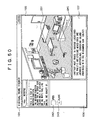
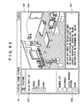
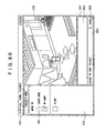
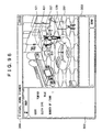
- FIG. 1 there is shown an exemplary configuration of the virtual space remote control system. This system is divided into the equipment on the user side and the equipment on the service provider side.
- a portable user terminal 1 including a PC, a PDA (Personal Digital Assistant), or a mobile telephone and connected to desired servers for example via a base station 4 and the Internet 5 realizes the following operations by executing a virtual home viewer program 51 (FIG. 2) by a CPU 31 (FIG. 2).
- a virtual home viewer program 51 FIG. 2
- a CPU 31 FIG. 2
- the portable user terminal 1 which is used by user A, connects to a virtual home DB server 21 for example on the service provider side via the base station 4 and the Internet 5 to get the information about the virtual home of user A and displays its image on the screen.
- This image of the virtual home shows a PC icon and a TV set icon corresponding to a PC 12 and a TV set 13, which exist in the real home of user A (hereafter referred to as user A's home).
- the portable user terminal 1 In response to a user operation performed on the PC icon or the TV set icon in the virtual home displayed on the screen, the portable user terminal 1 connects to a home server 11 constituting a home network 2 of user A's home via the base station 4 and the Internet 5, thereby sending control signals for controlling the PC 12 and the TV set 13.
- the home server 11 has a global IP address. Therefore, the portable user terminal 1 or the like can access the home server 11 via the Internet 5. From the portable user terminal 1 via the Internet 5, the home server 11 receives control signals for controlling the PC 12 and the TV set 13 and executes the middleware such as UPnP, thereby passing the received control signals to the PC 12 and the TV set 13 via a data bus 14.
- the middleware such as UPnP
- the PC 12 of user A's home connects to the virtual home DB server 21 for example on the service provider side via the Internet 5, thereby displaying the user A's virtual home on the screen. Also, in response to user's operation preformed on the PC icon or the TV set icon in the displayed virtual home, the PC 12 sends control signals for controlling the TV set 13 for example connected to the home server 11.
- the PC 3 which is used by user B, connects to the virtual home DB server 21 for example on the service provider side to display the user B's virtual home on the screen. Also, in response to user's operation performed on the PC icon or the TV set icon in the displayed virtual home, the PC 3 connects to the home server of user B's home via the Internet 5 to send control signals for controlling its PC (not shown) or the like connected to its home server (not shown).
- the user-side equipment includes the portable user terminals and PCs being operated by users other than user A and user B and there are also home servers for these users other than user A and user B, the illustrations thereof being omitted for the brevity of description.
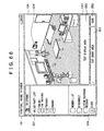
- the virtual home DB server 21 stores virtual home layout information (the external view, wall pattern, and floor material of the virtual home and the icon arrangement in the virtual home, for example), which is set by each user in a desired manner, and each user's event information (the information telling that messages addressed to that user are in the mailbox, the information indicative of applications for chat by other users, and so on).
- the virtual home DB server 21 provides these pieces of information to the portable user terminal 1 for example, which accesses the virtual home DB server 21 via the Internet 5.
- An authentication server 22 executes authentication processing on the portable user terminal 1 or the like, which has accessed the equipment on the service provider side via the Internet 5. To be more specific, the authentication server 22 provides the access right for the equipment on the service provider side and determines the validity or invalidity of the access right to be sent to the virtual home DB server 21, an inter-user-terminal communication relay server 23, or a user information holding server 24.
- the inter-user-terminal communication relay server 23 executes the processing associated with a plurality of users who use the virtual space remote control system. For example, the inter-user-terminal communication relay server 23 stores a member list of a user group to which each user belongs, manages the chat being executed between a plurality of users, and manages the conference synchronous information (details of which will be described later) being generated when a virtual room is shared.
- each user can belong to a plurality of user groups.
- the user information holding server 24 stores the personal data of each user; namely, the event detail information (mail addressed to that user and message text data for example) for event information, a variety of certificate data (details of which will be described later) obtained by each user, the text data written by the user by utilizing notepad capability, and the image data to be shared by other users, for example.
- an EPG (Electronic Program Guide) server 25 In response to a request by the portable user terminal 1 for example, which has accessed via the Internet 5, an EPG (Electronic Program Guide) server 25 provides EPG information including a television program guide and detail information about each program.
- EPG Electronic Program Guide
- An audio server 26 is a broadcasting server of so-called Internet radio and provides audio stream data in response to a request by the portable user terminal 1 or the like, which has accessed via the Internet 5.
- the equipment devices on the service provider side, the virtual home DB server 21 through the audio server 26, need not be arranged in a separate manner as shown; some of the servers may be integrated into one unit if required.
- the portable user terminal 1 incorporates the CPU (Central Processing Unit) 31.
- the CPU 31 is connected to an input/output interface 35 via a bus 34.
- the bus 34 is connected to a ROM (Read Only Memory) 32 and a RAM (Random Access Memory) 33.
- the input/output interface 35 is connected to an output block 36 for outputting sound or the like, an operator input block 37 based on an input device such as a keyboard and a touch panel for inputting operator commands by the user A, a display block 38 based on CRT (Cathode Ray Tube), LCD (Liquid Crystal Display), or the like on which images such as virtual home are shown, a storage block 39 based on a hard disk drive or the like for storing various programs and data, and a communication block 40 for performing communication via the base station 4 and the Internet 5.
- the input/output interface 35 is also connected to a drive 41, which reads and writes data on a recording medium such as a magnetic disk 42, an optical disk 43, a magneto-optical disk 44, or a semiconductor memory 45.
- the CPU 31 executes various processing operations to be described later in accordance with the virtual home viewer program 51 loaded from the storage block 39 into the RAM 33, this program being read from the above-mentioned recording medium into the storage block 39. This is the end of the description for the exemplary configuration of the portable user terminal 1.
- the PC 12 incorporates a CPU 61.
- the 61 is connected to an input/output interface 65 via a bus 64.
- the bus 64 is connected to a ROM 62 and a RAM 63.
- the input/output interface 65 is connected to an output block 66 for outputting sound or the like, an operator input block 67 based on an input device such as a keyboard and a mouse for inputting operator commands by the user A, a display block 68 based on CRT, LCD, or the like on which images such as virtual home are shown, a storage block 69 based on a hard disk drive or the like for storing various programs and data, and a communication block 70 for performing communication with the home server 11 and communication via the home server 11 and the Internet 5.
- an output block 66 for outputting sound or the like
- an operator input block 67 based on an input device such as a keyboard and a mouse for inputting operator commands by the user A
- a display block 68 based on CRT, LCD, or the like on which images such as virtual home are shown
- a storage block 69 based on a hard disk drive or the like for storing various programs and data
- a communication block 70 for performing communication with the home server 11 and communication via the home server 11 and
- the input/output interface 65 is also connected with a drive 83, which reads and writes data on a recording medium such as a magnetic disk 74, an optical disk 75, a magneto-optical disk 76, or a semiconductor memory 77, and a video encoder/decoder 71, which encodes and decodes AV signals of television broadcast for example.
- the video encoder/decoder 71 incorporates a tuner 72 for receiving television broadcast.
- the CPU 61 executes a virtual home viewer program 81, a HDD (Hard Disk Drive) video recorder 82, a audio data transmission service program 83, and a photograph data transmission service program 84 which are read from any of the recording media such as the magnetic disk 74 through the semiconductor memory 45 into the storage block 39 and then into the RAM 33, thereby realizing the four functions shown in FIG. 4, namely, a virtual home viewer 91, a HDD video recorder 92, an audio data transmission service 93, and a photograph data transmission service 94.
- these programs may be distributed by various recording media or through networks such as the Internet 5.
- the virtual home viewer 91 gets the information about the virtual home of user A from the virtual home DB server 21 via the Internet 5 to display the virtual home on the screen and, in response to user A's operation performed on the PC icon or the TV set icon in the virtual home, outputs the controls signals for controlling the PC 12 and the TV set 13 to the home server 11.
- the virtual home viewer 91 can reproduce so-called Internet radio as with the audio data transmission service 93 to be described later.
- the HDD video recorder 92 controls the video encoder/decoder 71 to encode AV signals of television broadcast or the like and store the resultant coded data into the storage block 69. Also, the HDD video recorder 92 reads and decodes the coded data from the storage block 69, displays the decoded AV signal video onto the display block 68, and outputs the sound from the output block 66. Alternatively, the recorder 92 supplies the decoded AV signal video to the TV set 13 via the data bus 14.
- the audio data transmission service 93 gets the steam data of so-called Internet radio from the audio server 26 and outputs the corresponding sound from the output block 66.
- the photograph data transmission service 94 displays the image data stored in the storage block 69 onto the display block 68 or a list of thumbnail images (contracted images) of plural pieces of image data onto the display block 68, for example. This is the end of the description for the exemplary configuration of the PC 12.
- an exemplary configuration of the PC 3 is substantially the same as the exemplary configuration of the portable user terminal 1 shown in FIG. 2 or the exemplary configuration of the PC 12 shown in FIG. 3, so that the description of the exemplary configuration of the PC 3 will be skipped.
- the home server 11 and the virtual home DB server 21 through the user information holding server 24 are configured in substantially the same manner as the exemplary configuration of the PC 12 shown in FIG. 3, so that the description of the exemplary configuration of each of these components will be skipped.
- the home server 11 and the virtual home DB server 21 through the user information holding server 24 execute various processing operations to be described later by which the CPUs incorporated in each server carry out predetermined programs.
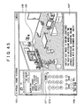
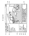
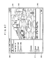
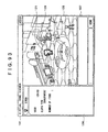
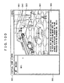
- FIG. 5 there is shown an example of a virtual home viewer window displayed on the screen of the portable user terminal 1 for example.
- the virtual home viewer window 101 is divided into a main panel 105 in which the image of the virtual home is displayed, a control panel 106 in which the information about an icon selected by the user from among those displayed in the main panel 105, and a communication panel 107 in which chat, mail text, and news for example are displayed.
- a mascot 121 exists that autonomously moves around in the room and that visits virtual homes of other users as an agent for this user for example.
- the mascot as used herein has the capabilities of invoking the impression that the user is visiting the currently displayed place, drawing off user's attention to the change in the state of the virtual home viewer program, allowing the user to visually recognize the visiting own virtual home by an other user, and carrying an icon when visiting the virtual home of an other user. Also, the mascot has the capabilities of acting for the user's processing in some manner as with the agent disclosed in Japanese Patent Laid-open No. 2002-44765. However, the mascot need not always has these capabilities of acting for the user's processing as the agent.
- the virtual room is arranged with a door icon 122, which is clicked when by the mascot 121 visits an other user's home, a mailbox icon 123, which is clicked when mail addressed to that user is received, a telephone icon 124, which is clicked when talking (actually chatting) with an other member of the member group to which this user belongs, a PC icon 125, which is clicked to control the really existing PC 12 in user A's home, and a TV set icon 126, which is clicked to control the TV set 13 really existing in user A's home.
- the virtual room is arranged with a sofa icon 127 and a table icon 128, which are furniture, and a pot plant icon 129 and a trash box icon 130, which are indoor ornaments and small objects (hereafter referred to as items).
- the icons, the PC icon 125 through the trash box icon 130, can be arranged at any places in the room.
- the items icons such as the pot plant icon 129 may be taken out of the room and presented to other users.
- the virtual room is arranged with a closet icon 131, which is clicked to accommodate item icons such as the pot plant icon 129 (the accommodated icons are hidden from the screen) or to bring out accommodated icons into the room.
- the user can select the designs of icons, the patterns of virtual room wallpapers, and the materials of the floor or the like from among prepared options.
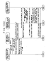
- the following describes a sequence of processing operations being carried out when the CPU 31 of the portable user terminal 1 executes the virtual home viewer program 51 loaded in the RAM 33.
- the subject of the action of the portable user terminal 1 is the virtual home viewer program 51.
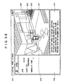
- the virtual home viewer program 51 When the virtual home viewer program 51 is started up, the external view of user A's home is displayed in the main panel 105 of the screen as shown in FIG. 8. For the displaying of this image, the layout information supplied from the virtual home DB server 21 at the last login and cached (or held) in the storage block 39 or the like is used. A password entry box 108 and "Enter Home" button 109 are displayed in the control panel 106.
- the virtual home viewer program 51 accesses the virtual home DB server 21 via the base station 4 and the Internet 5 to send a login request in step S1.
- the virtual home DB server 21 sends the URL (Uniform Resource Locator) of the authentication server 22 back to the virtual home viewer program 51 via the Internet 5 and the base station 4 in step S11.
- URL Uniform Resource Locator
- step S2 the virtual home viewer program 51 accesses the authentication server 22 via the base station 4 and the Internet 5 to send the password and ID (the personal ID preset for user A or the device ID set to the portable user terminal 1) being entered by user A along with a verification request.
- the password and ID the personal ID preset for user A or the device ID set to the portable user terminal 1
- the authentication server 22 checks the validity of the password and ID. If the password or ID are found to be valid, the server 22 supplies the access right to the virtual home viewer program 51 via the Internet 5 and the base station 4, thereby allowing access to all devices on the service provider side in step S21.
- step S3 the virtual home viewer program 51 sends the granted access right to the virtual home DB server 21 via the base station 4 and the Internet 5.
- step S12 the virtual home DB server 21 requests the authentication server 22 for verifying the access right send from the virtual home viewer program 51.
- step S22 the authentication server 22 verifies the access right and sends the result of the verification to the virtual home DB server 21.
- step S13 if the verification result received from the authentication server 22 indicates that the access right is authentic, then the virtual home DB server 21 notifies the virtual home viewer program 51 of the successful login operation via the Internet 5 and the base station 4.
- the virtual home viewer program 51 can continue the subsequent processing. This is the end of the description of the login processing.
- step S31 the virtual home viewer program 51 requests the virtual home DB server 23 for the layout information about the user A's virtual home via the base station 4 and the Internet 5.
- the virtual home DB server 23 supplies the most recent layout information about the user A's virtual home stored in the virtual home DB server 23 to the virtual home viewer program 51 via the Internet 5 and the base station 4 in step S41.
- step S32 the virtual home viewer program 51 compares the captured most recent layout information with the layout information cached in the storage block 39 or the like and requests the virtual home DB server 21 for the updated data such as icon image data, which do not exist in the cached layout information but exist in the most recent layout information, via the base station 4 and the Internet 5.
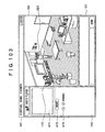
- the virtual home DB server 21 supplies the requested updated data such as icon image data to the virtual home viewer program 51 via the Internet 5 and the base station 4 in step S42. Then, in step S33, the virtual home viewer program 51 displays the image of the virtual room in the main panel 105 as shown in FIG. 10. At this moment, because the user selects none of the icons in the virtual room, the state (age of home, total login time, wall type, floor type, etc.) of the virtual home is displayed in the control panel 106. This is the end of the description of the layout information acquisition processing.
- the event information is stored in the virtual home DB server 21 and indicates an action performed on user A by an other user (for example, the arrival of mail to user A, the recording of answerphone message for user A, or the visiting by an other user to user A's virtual home).
- step S51 the virtual home viewer program 51 requests the virtual home DB server 21 for the event information of user A via the base station 4 and the Internet 5.
- the virtual home DB server 21 supplies the event information of user A via the Internet 5 and the base station 4 in step S61.
- step S52 on the basis of the user A's event information supplied from the virtual home DB server 21, the virtual home viewer program 51 accesses the user information holding server 24 via the base station 4 and the Internet 5 to request for the event detail information corresponding to the event information.
- the event detail information herein denotes the text data, which are specific contents of mail or message addressed to user A.
- this is the first connection to the user information holding server 24 since the login, so that, like the processing of steps S3, S12, and S22 of the above-mentioned login processing, such a sequence of processing operations is executed before requesting for the event detail information corresponding to the event information as that the virtual home viewer program 51 sends the access right obtained from the authentication server 22 to the user information holding server 24, the user information holding server 24 requests the authentication server 22 for the verification of the access right sent from the virtual home viewer program 51, and the authentication server 22 verifies the access right and sends the result of the verification to the user information holding server 24.
- step S71 the user information holding server 24 supplies the requested event detail information to the virtual home viewer program 51 via the Internet 5 and the base station 4. This is the end of the description of the event information acquisition processing.
- this event information acquisition processing will be periodically executed hereafter in predetermined timing; namely, this processing is executed in a polling manner.
- home network information acquisition processing is executed to understand the state of the equipment components constituting the home network 2 of user A.
- the following describes this home network information acquisition processing with reference to the flowchart shown in FIG. 12.
- step S81 the virtual home viewer program 51 accesses the home server 11 via the base station 4 and the Internet 5 to request for the searching of the home network 2.
- the home server 11 searches for the home network 2 in step S91.
- the home server 11 requests all the devices connected thereto via the data bus 14 for a response.
- the TV set 13 sends the information for identifying itself to the home server 11 in step S101.
- the PC 12 connected to the home server 11 via the data bus 14 executes the substantially the same processing, although not shown. Subsequently, the PC 12 executes the substantially the same processing as the TV set 13, the description of which is skipped.
- step S92 on the basis of the response from the TV set 13 and the PC 12 connected to the data bus 14, the home server 11 creates a list of home network services indicative of a list of devices constituting the home network 2 and supplies the created list to the virtual home viewer program 51 via the Internet 5 and the base station 4.
- the virtual home viewer program 51 requests the home server 11 via the base station 4 and the Internet 5 for the detail information about the devices (also referred to as network devices) constituting the home network 2 in step S82.
- the detail information about the network devices herein includes the items that can be controlled from the virtual home viewer program 51 (in the case of TV set 13, power on/off, volume up/down, channel change, multiplexed audio switching, and input signal switching, for example; in the case of the PC 12, the realizable various operations of the HDD video recorder 92, the audio data transmission service 93, and photograph data transmission service 94 for example) and the information about the operator buttons being displayed in the control panel 106 when controlling network devices.
- the home server 11 requests the TV set 13 constituting the home network 2 for the detail information in step S93.
- the TV set 13 supplies the detail information to the home server 11 in step S102.
- the home server 11 supplies the detail information received from each network device to the virtual home viewer program 51 via the Internet 5 and the base station 4.
- step S83 the virtual home viewer program 51 requests the home server 11 via the base station 4 and the Internet 5 for the current status information of each network device.
- the home server 11 requests the TV ser 13 for the current status information in step S95.
- step S103 in response to this request, the TV set 13 supplies the current status information to the home server 11.
- the current status information of the TV set 13 includes a channel being tuned in and a volume setting for example.
- step S96 the home server 11 supplies the current status information received from each network device to the virtual home viewer program 51 via the Internet 5 and the base station 4. This is the end of the description of the home network information acquisition processing.
- the virtual home viewer program 51 changes the displaying of icons in the main panel 105 representative of the network devices arranged in the virtual room. For example, if the TV set 13 of user A is receiving a television program, an image is displayed on the screen of the TV set icon 126.
- member list acquisition processing is executed. The following describes this member list acquisition processing with reference to the flowchart shown in FIG. 13.
- step S111 the virtual home viewer program 51 accesses the inter-user-terminal communication relay server 23 via the base station 4 and the Internet 5 to send the server 23 the access right granted from the authentication server 22 in the above-mentioned login processing, thereby requesting for the member list.
- the inter-user-terminal communication relay server 23 requests the authentication server 22 for the verification of the access right received from the virtual home viewer program 51.
- the authentication server 22 verifies the access right and supplies the result of the verification to the user information holding server 24 in step S131.
- step S122 if the verification result received from the authentication server 22 indicates that the access right is authentic, the inter-user-terminal communication relay server 23 supplies the member list of the user group to which user A belongs to the virtual home viewer program 51 via the Internet 5 and the base station 4. This is the end of the description of the member list acquisition processing.
- the logout processing starts when the user clicks "Close” button 102 in the virtual home viewer window 101.
- the logout processing starts when "End” button 137, among various buttons (to be detailed later with reference to FIG. 75), which are displayed in the control panel 106 upon clicking of the door icon 122 shown in the main panel 105, is clicked as shown in FIG. 15.
- step S141 the virtual home viewer program 51 sends the current layout information (indicative of the arrangement and orientation of each icon in the virtual room) to the virtual home DB server 21 via the base station 4 and the Internet 5, thereby requesting for the updating of the layout information stored in the virtual home DB server 21.
- step S151 in response to this update request, the virtual home DB server 21 updates the layout information stored therein. Then, the virtual home DB server 21 supplies the virtual home viewer program 51 with the completion of the updating of the current layout information via the Internet 5 and the base station 4.
- step S142 the virtual home viewer program 51 sends the personal data including the text data such as memo entered by use of the notepad capability (to be described later with reference to FIGS. 47 through 50) to the user information holding server 24 via the base station 4 and the Internet 5 to request for the updating of the personal data stored in the user information holding server 24.
- step S161 in response to this update request, the virtual home DB server 21 updates the personal data of user A stored therein. Subsequently, the virtual home DB server 21 notifies the virtual home viewer program 51 of the completion of the updating of the personal information via the Internet 5 and the base station 4.
- step S143 the virtual home viewer program 51 requests the virtual home DB server 21 for logout via the base station 4 and the Internet 5.
- the virtual home DB server 21 sets itself so as to reject any access from the virtual home viewer program 51 until logged in again and notifies the virtual home viewer program 51 of the completion of logout via the Internet 5 and the base station 4.
- step S144 the virtual home viewer program 51 requests the user information holding server 24 for logout via the base station 4 and the Internet 5.
- the user information holding server 24 sets itself so as to reject any access from the virtual home viewer program 51 until logged in again and notifies the virtual home viewer program 51 of the completion of logout via the Internet 5 and the base station 4.
- step S145 the virtual home viewer program 51 requests the inter-user-terminal communication relay server 23 for logout via the base station 4 and the Internet 5.
- step S171 in response to this logout request, the inter-user-terminal communication relay server 23 sets itself so as to reject any access from the virtual home viewer program 51 until logged in again and notifies the virtual home viewer program 51 of the completion of logout via the Internet 5 and the base station 4.
- the processing of the virtual home viewer program 51 is completed. This is the end of the description of the login processing.
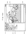
- the user can change the arrangement of desired icons (however, some icons such as the mailbox icon 123, which belongs to the door icon 122, cannot be moved).
- the user can drag the sofa icon 127 of the virtual room shown in FIG. 16 and drop the icon at the upper right side of the table icon 128, thereby changing the arrangement of the sofa icon 127 as shown in FIG. 17.
- the user can switch between its orientations, the left-oblique and the right-oblique toward the user (however, some icons cannot be changed in orientation).
- double-clicking the sofa icon 127 in the right-oblique orientation in the virtual room shown in FIG. 17 can switch the position to the left-oblique orientation as shown in FIG. 18.
- dragging a board game set icon 141 in the virtual room shown in FIG. 18 and dropping it on the table icon 128 can arrange the board game set icon 141 on the table icon 128 as shown in FIG. 19.
- the board game set icon 141 may be arranged behind the table icon 128. To be more specific, dragging the board game set icon 141, from the lower right to the upper left in the screen, to the table icon 128 and dropping the board game set icon 141 thereon can arrange the board game set icon 141 on the table icon 128 as shown in FIG. 20A.
- the layout information is updated accordingly and the updated layout information is sent to the virtual home DB server 21 in a predetermined period.
- the user can drag a desired icon in the virtual room and drop the icon onto the closet icon 131, thereby accommodating the icon into the closet (however, some icons cannot be accommodated in the closet).
- the closet icon 131 When an icon has been accommodated in the closet icon 131, the closet icon 131 becomes the selected state (in the figure, the framed state) as shown in FIG. 22. When the closet icon 131 is in the selected state, a popup list 151 is displayed adjacent to the closet icon 131.
- the popup list 151 shows the accommodated icons in reduced size in the order of accommodation and up to the predetermined number (five in the case of FIG. 22). If more than the predetermined number of icons are accommodated in the closet, a scroll button 159 is shown in the popup list 151. This scroll button 159 is clicked to display all the accommodated icons by scrolling.
- control panel 106 shows "Display Item List” button 157 and "Close” button 158.
- the "Display Item List” button 157 is clicked when displaying all icons accommodated in the closet into the main panel 105 as shown in FIG. 23.
- the "Close” button 158 is clicked when returning the display of the main panel 105 to the virtual room when the item list is displayed in the main panel 105.
- the control panel 106 shows the property of the selected icon and "Close" button 161 which is clicked to return the display of the main panel 105 to the virtual room.
- the property of the selected board game set icon 141 does not especially exist, so that only the "Close” button 161 is shown.
- the "Close” button 161 is clicked, the display of the main panel 105 is returned to the virtual room as shown in FIG. 25.
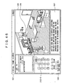
- FIG. 26 shows that an ashtray icon 154 accommodated in the closet is arranged on the table icon 128 in the virtual room.
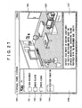
- FIG. 27 there is shown a state in which the PC icon 125 is selected in the virtual room shown in the main panel 105.
- the control panel 106 shows a "Video Recorder” button 161, "Audio Player” button 162, and "Photo Album” button 163.
- the button correspond to the capabilities realized by the PC 12 in user A's home controllable from the virtual home viewer program 51.
- the "Video Recorder” button 161 is clicked when controlling the HDD video recorder 92, which can be realized by the PC 12.
- the "Audio Player” button 162 is clicked when controlling the audio data transmission service 93, which can be realized by the PC 12.
- the "Photo Album” button 163 is clicked when controlling the photograph data transmission service 94, which can be realized by the PC 12.
- the control panel 106 shows "Divide Function” button 164 that is clicked to show the icons, which correspond to the HDD video recorder 92, the audio data transmission service 93, and the photograph data transmission service 94, in the virtual room.
- "Divide Function” button 164 when the "Divide Function" button 164 is clicked, a video recorder icon 171, an audio player icon 172, and a photo album icon 173 appear in an empty place on the floor in addition to the PC icon 125.
- the user can change the arrangement of the video recorder icon 171, the audio player icon 172, and the photo album icon 173 as desired.
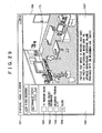
- FIG. 29 there is shown a state in which the arrangement of the video recorder icon 171 and the audio player icon 172 has been changed from the state shown in FIG. 28 and the video recorder icon 171 is selected by the user.
- the control panel 106 shows the current state of the HDD video recorder 92 as the property of the video recorder icon 171. It should be noted that, in order to show the current state of the HDD video recorder 92, the current status information of the PC 12 obtained by the home network information acquisition processing executed earlier is used.
- control panel 106 shows "TV Program Guide” button 181 being clicked to show a television program guide (hereafter referred to as a TV program guide) in the main panel 105, "Check Preset Recording” button being clicked to show the information about preset recording in the main panel 105, "Recorded Program List” button 183 being clicked to show a list of recorded programs in the main panel 105, and "Close” button 184 being clicked to return the display of the main panel 105 to the display of the virtual room.
- TV Program Guide “TV Program Guide” button 181 being clicked to show a television program guide (hereafter referred to as a TV program guide) in the main panel 105
- Check Preset Recording” button being clicked to show the information about preset recording in the main panel 105
- "Recorded Program List” button 183 being clicked to show a list of recorded programs in the main panel 105
- “Close” button 184 being clicked to return the display of the main panel 105 to the display of the virtual room.
- FIG. 30 there is shown a state in which a TV program guide is shown in the main panel 105 in response to the clicking of the "TV Program Guide” button 181.
- the EPG information obtained by the virtual home viewer program 51 from the EPG server 25 is used.
- step S181 the virtual home viewer program 51 accesses the EPG server 25 via the base station 4 and the Internet 5 to request for EPG information.
- the EPG server 25 supplies the requested EPG information to the virtual home viewer program 51 via the Internet 5 and the base station 4 in step S191. This is the EPG information acquisition processing.
- the control panel 106 shows "Record Mode” setting box 191 being clicked to set the recording mode for recording the selected program to the standard mode, the high quality mode, or the long time mode, "Record” button 192 being clicked to preset the recording of the selected program, and "Close” button 193 being clicked to return the display of the main panel 105 to the state in which the video recorder icon 171 is selected in the virtual room.
- the virtual home viewer program 51 sends to the home server 11, via the base station 4 and the Internet 5, a control signal for instructing the HDD video recorder 92 to preset the recording of the selected program.
- the home server 11 sends this control signal to the PC 12 via the data bus 14.
- the HDD video recorder 92 of the PC 12 executes the preset recording in accordance with this control signal.
- user A can remotely control the preset recording of TV programs through the PC 12 of user A's home from the operator screen of the virtual home viewer program 51, which is executed on the portable user terminal 1.
- processing by the virtual home viewer program 51 executed on the portable user terminal 1 can also be executed by the virtual home viewer 91, which is realized by executing the virtual home viewer program 81 by the PC 12 of user A's home.
- the virtual home viewer 91 gets content list information from the HDD video recorder 92.
- step S201 the virtual home viewer 91 requests the HDD video recorder 92 for content list information.
- step S211 in response to this request, the HDD video recorder 92 supplies the content list information to the virtual home viewer 91. This is the end of the description of the content list information acquisition processing.
- the control panel 106 shows, as shown in FIG. 37, the information about the contents of the selected recorded program, "Reproduce” button 194 being clicked to reproduce the selected recorded program, "Pause” button 195 being clicked to temporarily stop reproduction, "Stop” button 196 being clicked to stop reproduction, "Delete” button 197 being clicked to delete the selected recorded program, and "Close” button 198 being clicked to return the display of the main panel 105 to the state in which the video recorder icon 171 is selected in the virtual room.
- step S221 the virtual home viewer 91 requests the HDD video recorder 92 for the stream reproduction of a selected recorded program.
- step S231 in response to this request, the HDD video recorder 92 starts reproducing the recorded program and supplies its stream data to the virtual home viewer 91.
- step S222 when the user clicks "Pause” button 195 or the "Stop” button 196 shown in the control panel 106 of the virtual home viewer 91, the virtual home viewer 91 requests the HDD video recorder 92 to stop reproduction in step S222.
- step S232 in response to this request, the HDD video recorder 92 stops reproduction of the recorded program, thereby stopping the supply of the stream data to the virtual home viewer 91 and notifies the virtual home viewer 91 of the stop of supplying the stream data. This is the end of the description of the processing of displaying a recorded program onto the main panel.
- the following describes the processing of displaying the video of a recorded program reproduced by the HDD video recorder 92 onto the TV set 13, with reference to the flowchart shown in FIG. 43.
- step S241 the virtual home viewer 91 outputs a control signal to the TV set 13 via the data bus 14 that instructs the TV set 13 to get the stream data of the recorded program from the HDD video recorder 92.
- step S251 in response to this control signal, the TV set 13 requests the HDD video recorder 92 via the data bus 14 for the stream reproduction of the recorded program.
- step S261 the HDD video recorder 92 notifies the TV set 13 via the data bus 14 of the acknowledgement for this request.
- step S252 the TV set 13 notifies the virtual home viewer 91 via the data bus 14 of the acknowledgement by the HDD video recorder 92 for the stream reproduction.
- step S262 the HDD video recorder 92 starts reproducing the recorded program and supplies the stream data to the TV set 13 via the data bus 14.
- step S242 a control signal to the TV set 13 via the data bus 14 that instructs the TV set 13 to stop the acquisition of the stream data of the recorded program from the HDD video recorder 92.
- step S252 in response to this control signal, the TV set 13 requests the HDD video recorder 92 via the data bus 14 for stopping the supply of the stream data.
- step S263 in response to this request, the HDD video recorder 92 stops reproducing the recorded program, thereby stopping the supply of the stream data to the TV set 13, notifying the TV set 13 of the stopping of the supply of the stream data.
- TV set 13 notifies the virtual home viewer 91 via the data bus 14 of the acknowledgement by the HDD video recorder 92 of the stopping of the stream data supply. This is the end of the description of the above-mentioned processing.
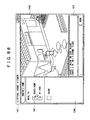
- FIG. 44 there is shown a state in which the user selects TV set icon 126 in the virtual room in the main panel 105.
- Selection of the TV set icon 126 displays, on the control panel 106, the state of the TV set 13, which really exists in user A's home (currently, nothing is displayed because the power to the TV set 13 is off), and the buttons for controlling the TV set 13, namely, "POWER" button 211 for tuning on/off the power, numeric buttons 212 for specifying channels of the TV set 13, and "Volume” button 213 for controlling the volume as the property of the TV set icon 126.
- the virtual home viewer 91 When the user clicks the "POWER" button 211, the virtual home viewer 91 outputs a control signal to the home server 11 to turn on the power to the TV set 13.
- the home server 11 relays this control signal to the TV set 13.
- the TV set 13 In response to this control signal from the virtual home viewer 91, the TV set 13 turns on its power, starting the reception of the channel (for example, 10ch) currently set.
- the virtual home viewer 91 changes the TV set icon 126 to the power-on state as shown in FIG. 45. Namely, an image is displayed on the screen of the TV set icon 126. Also, the virtual home viewer 91 displays the channel currently received (10ch in this example) and the information associated with that program onto the control panel 106 as the property of the TV set icon 126.
- the virtual home viewer 91 outputs a control signal to the home server 11 to instruct the TV set 13 to receive 6ch.
- the home server 11 relays this control signal to the TV set 13.
- the TV set 13 responds to the virtual home viewer 91 and switches channel from 10ch to 6ch.
- the virtual home viewer 91 changes the image shown on the screen of the TV set icon 126 as shown in FIG. 46. Also, the virtual home viewer 91 displays on the control panel 106 the channel currently received by the TV set 13 (6ch in this example) and the information about that program as the property of the TV set icon 126.
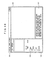
- FIG. 47 there is shown a state in which the notepad icon 231 on the table icon 128 is selected in the virtual room shown in the main panel 105.
- the control panel 106 displays the head portion "4/3 Baseball Training " of the page (in this example, page 3/500) opened last, as the property of the notepad icon 231.
- the control panel 106 also displays "Page” button 232 being clicked to select a page of the notepad to be displayed as the property, "New” button 233 being clicked to open a new page in the main panel 105, "Open” button 234 being clicked to display the entire selected page as the property in the main panel 105, "Cut” button 235 being clicked to cut a selected page from the notepad to generate a separate memo sheet icon 241 (FIG. 50), and "Close” button 236 being clicked to return from the opened page of the notepad to the virtual room.
- FIG. 48 there is shown a state in which a new page is displayed in the main panel 105 upon clicking of the "New" button 233.
- the user can enter text into the page displayed in the main panel 105 as shown in FIG. 49.
- FIG. 50 there is shown a state in which, upon clicking of the "Cut" button 235, a selected page is cut from the notepad and the memo sheet icon 241 corresponding to one sheet of notepad has appeared separate from the notepad icon 231.
- the memo sheet icon 241 is selected and the control panel 106 displays the head portion ("This is a test of notepad ") of the text written in the memo sheet 241 as the property of the memo sheet icon 241.
- the control panel 106 displays "Open” button 242 being clicked to display the text written on the notepad onto the main panel 105 and "Close” button 243 being clicked to return the display of the main panel 105 from the text to the virtual room.
- the memo sheet icon 241 may be passed to other users in the communication processing, which will be described later.
- the text written in each page of the notepad, the arrangement and orientation of the newly created memo sheet icon 241, and the text written on the memo sheet are uploaded to the user information holding server 24 at predetermined time intervals as the user's personal data.
- the following describes various communication processing operations based on the virtual space remote control system in which a plurality of users involve.
- the parties with whom user A can execute communication processing are restricted to the members of the user group to which user A belongs.
- user A can talk (actually, exchange messages by chat) with any member of the user group to which user A belongs.
- the control panel 106 displays parties whom user A can call, namely, a called party list 251 indicative of the names of members in the user group to which user A belongs, as the property of the telephone icon 124.
- the called party list 251 shows the names of members of the user group to which user A belongs, in the predetermined number. If the number of members of this user group exceeds a predetermined number, a scroll button (not shown) is displayed by which all member names are scrolled to be shown. Beside each member name, a call button is shown. For example, the call button for "Yumiko" is clicked, user A can talk with "Yumiko” who is a member of the same user group as user A (details of which will be described later).
- the member list obtained in the startup sequence is referenced.
- the member list acquisition processing described above with reference to FIG. 13 is executed again to get the most recent member list, thereby updating the display of the called party list 251.
- control panel 106 displays "Member List” button 252 being clicked to display on the main panel 105 the list of members of the user group to which user A belongs, "Disconnect” button 253 being clicked to end talk, "Listen Recorded Message” button 254 being clicked to listen to a recorded message (actually, text data) recorded by a user who called user A, and "Close” button 255 being clicked to return the display of the main panel 105 from the contents of recorded message to the virtual room.
- the main panel 105 displays a list of members of the user group to which user A belongs as shown in FIG. 52.
- the member list shown in the main panel 105 includes "User Search" button 261 in addition to member names.
- the control panel 106 When the "User Search" button 261 is clicked, the control panel 106 is switched from the display of the called party list 251 for example to the display for user search, as shown in FIG. 53. To be more specific, the control panel 106 displays an entry box 271 in which a user name is entered as a search condition, "Search" button 272 being clicked to start a search operation and display a search result in the main panel 105, "Member List” button 271 being clicked to return the display of the main panel 105 from search result to member list, and "Close” button 274 being clicked to return the display of the main panel 105 to the virtual room.
- search condition "Nanako" is sent to the inter-user-terminal communication relay server 23 via the base station 4 and the Internet 5.
- the inter-user-terminal communication relay server 23 executes a search operation on all users and sends back the search result, thereby displaying a list of user names including "Nanako" in the main panel 105.
- control panel 106 displays the property of the selected user name "Nanako" (the text prepared and intended for public display by "Nanako" herself), "Register Member” button 281 being clicked to additionally register the user having selected user name with the user group, and "Close” button 282 being clicked to return the display of the main panel 105 to the member list.
- the following describes the processing of deleting a member from the user group to which user A belongs. For example, as shown in FIG. 57, if "Hideo" is selected from the members of the user group with the member list displayed in the main panel 105, the control panel 106 displays the property (the text prepared and intended for public display by "Hideo" himself), "Delete Member” button 291 being clicked to delete the user having the selected user name from the user group and "Close” button 292 being clicked to return the display of the main panel 105 to the virtual room.
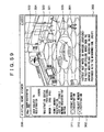
- FIG. 59 shows the window of a virtual home viewer being displayed on the screen of the PC 3, which is operated by user B.
- This window is also divided into a main panel 301, a control panel 302, and a communication panel 303.
- the main panel 301 shows the virtual room of user B.
- the virtual room of user B is arranged with a mascot 321, a door icon 322, a mailbox icon 323, a telephone icon 324, and a PC icon 325 for example.
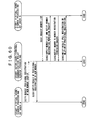
- step S271 the virtual home viewer program 51 (hereafter referred to as virtual home viewer A) of the portable user terminal 1 of user A requests the inter-user-terminal communication relay server 23 for the provisional registration of user B via the base station 4 and Internet 5.
- step S281 the inter-user-terminal communication relay server 23 provisionally registers user B with the user group to which user A belongs and notifies the virtual home viewer A of the completion of the provisional registration.
- the user B recognizes its provisional registration with the user group to which user A belongs only when user B obtains the member list of the user group to which user B belongs from the inter-user-terminal communication relay server 23.
- step S291 the virtual home viewer program of the PC 3 of user B (hereafter referred to as a virtual home viewer B) requests the inter-user-terminal communication relay server 23 for the member list via the Internet 5 as a startup sequence.
- the inter-user-terminal communication relay server 23 sends, to virtual home viewer B via the Internet 5, the member list of the user group to which user B belongs (user A is not yet included in this member list) and a member registration permission enquiry for confirming whether user B can be registered with the user group to which user A belongs.
- a member registration form icon 326 is delivered to the mailbox icon 323 of the virtual room of user B as shown in FIG. 59.
- the control panel 302 displays the information indicative of the provisional registration of user B with the user group to which user A belongs, "Permit Member Registration” button 311 being operated to permit the full registration and "Reject Member Registration” button 312 being operated to reject the registration.
- step S283 the inter-user-terminal communication relay server 23 fully registers user B with the user group to which user A belongs or deletes user B from the user group of user A with which user B is provisionally registered, notifying the virtual home viewer B thereof via the Internet 5.
- notification of the full registration of user B is not explicitly sent to virtual home viewer A.
- user A can determine whether user B has been fully registered as the member by checking the member list for the name of user B when the member list is displayed in virtual home viewer A.
- talk can be executed between the members of the same user group.
- user A may only select the telephone icon 124 in the virtual room to display the called party list 251 in the control panel 106 as shown in FIG. 61 and click "Yumiko" button in the members included in the called party list 251 as shown in FIG. 62.
- step S301 virtual home viewer A requests the virtual home DB server 21 via the base station 4 and the Internet 5 for the current status of user B.
- step S311 the inter-user-terminal communication relay server 23 sends, to virtual home viewer A via the Internet 5 and the base station 4, the current status of user B; namely, user B is in the logout state (talk disabled), in the login state and at home (talk enabled), in the login state and at home but talking with an other user (talk disabled), or in the login state and visiting an other user's virtual room (talk disabled).
- the current status of user B namely, user B is in the logout state (talk disabled), in the login state and at home (talk enabled), in the login state and at home but talking with an other user (talk disabled), or in the login state and visiting an other user's virtual room (talk disabled).
- step S321 virtual home viewer A requests the virtual home DB server 21 via the base station 4 and the Internet 5 for a telephone chat call event for user B.
- step S331 the virtual home DB server 21 generates the telephone chat call event for user B and notifies virtual home viewer A via the Internet 5 and the base station 4 of the acknowledgement of this event request.
- virtual home viewer A subsequently periodically requests the inter-user-terminal communication relay server 23 via the base station 4 and Internet 5 for a telephone chat text, which is sent from user B to user A. It should be noted that, if user B does not answer the telephone chat call, nothing is sent back.
- step S341 by the event information acquisition processing, which is periodically executed, virtual home viewer B requests the virtual home DB server 21 via the Internet 5 for event information.
- step S332 the virtual home DB server 21 notifies virtual home viewer B via the Internet 5 of the generation of a telephone chat event upon request by user A.
- virtual home viewer B displays the telephone icon 324 in the virtual room shown in the main panel 301 in a highlighted manner (the icon is partially lighted or entirely blinked) and generates the sound of the beep for the telephone as shown in FIG. 65. Also, virtual home viewer B displays the name of telephone chat originator and "Answer" button 341 being clicked to answer the call of telephone chat in the control panel 302.
- the communication panel 303 displays an text entry area 342 being entered the telephone chat text, "SEND" button 343 being clicked to send the text entered in the text entry area 342, and a text display area 344 being displayed the telephone chat text.
- step S342 virtual home viewer B sends the information that the telephone chat call has been answered and telephone chat text "Hello" to the inter-user-terminal communication relay server 23 via the Internet 5.
- step S351 the inter-user-terminal communication relay server 23 returns the telephone chat text addressed to user B from user A. It should be noted that, in the phase of step S351, the telephone chat text from user A to user B does not exist, so that nothing is sent back.
- virtual home viewer A waiting for the answer from user B to which telephone chat call was sent has been periodically requesting the inter-user-terminal communication relay server 23 via the base station 4 and the Internet 5 for telephone chat text to be sent from user B to user A.
- the inter-user-terminal communication relay server 23 sends, via the Internet 5 and the base station 4, information that user B has answered the telephone chat call and text "Hello" of the telephone chat sent from user B to user A to virtual home viewer A in response to this request in step S352.
- virtual home viewer A displays that talk is being made with "Yumiko" in the called party list 251 of the control panel 106 as shown in FIG. 66. Also, virtual home viewer A changes the display of the communication panel 107 to a text entry area 351, which is entered the telephone chat text, "SEND" button 352, which is clicked to send the telephone chat text entered in the text entry area 351, and a text display area 353, which is displayed the telephone chat text.
- virtual home viewer A displays, in the text display area 353, the telephone chat text addressed to B entered in the text entry area 351, sends the telephone chat text to the inter-user-terminal communication relay server 23 via the base station 4 and the Internet 5, obtains a telephone chat text addressed to user A held in the inter-user-terminal communication relay server 23 at that moment, and also displays the obtained telephone chat text in the text display area 353 as shown in FIG. 67. Further, virtual home viewer A periodically gets the telephone chat text addressed to user A from the inter-user-terminal communication relay server 23 via the base station 4 and the Internet 5 and also displays the obtained telephone chat text in the text display area 353. Virtual home viewer B also executes the similar processing.
- step S361 virtual home viewer A notifies the inter-user-terminal communication relay server 23 via the base station 4 and the Internet 5 of the disconnection, namely the end of telephone chat.
- step 371 the inter-user-terminal communication relay server 23 sends back the acknowledgement of the disconnect operation and the telephone chat addressed to user A received up to this moment.
- virtual home viewer A returns the displays of the main panel 105 and the control panel 106 to the state as it was before the starting of the telephone chat.
- virtual home viewer B when virtual home viewer B periodically requests the inter-user-terminal communication relay server 23 via the Internet 5 for a telephone chat text addressed to user B in step S381, then, in response to this request, the inter-user-terminal communication relay server 23 notifies virtual home viewer B via the Internet 5 of the disconnection with user A, namely the end of the telephone chat in step S372. In response to this notification, virtual home viewer B returns the displays of the control panel 302 and the communication panel 303 to the state at it was before the starting of the telephone chat. This is the end of the description of the telephone chat end processing.
- answerphone message recording processing which is executed when user A leaves a message to user B because user B is in the talk disabled state, with reference to FIG. 70.
- This answerphone recording processing is executed if the current status of user B obtained by the above-mentioned current status information acquisition processing indicates that user B is in the login state and not at home (talk enabled) in the virtual home.
- step S391 virtual home viewer A displays (Answerphone) in the called party list 251 of the control panel 106 as the information indicative that the called party is in the talk disabled state as shown in FIG. 71. Also, virtual home viewer A switches the display of the communication panel 107 to the display of talk chat, thereby displaying preset message "I'm away from home right now.” in the text display area 353.
- step S401 the user information holding server 24 stores the message and notifies virtual home viewer A via the Internet 5 and the base station 4 of the acknowledgement of the request for storing the object.
- step S392 virtual home viewer A notifies the virtual home DB server 21 via the base station 4 and the Internet 5 of the event information (the leaving of the message at the answerphone of user B).
- step S411 the virtual home DB server 21 notifies the virtual home viewer A via the Internet 5 and the base station 4 of the reception of the event information.
- step S421 the virtual home DB server 21 sends the event information (that there is a message left at the answerphone of user B) to virtual home viewer B via the Internet 5 in step S412. It should be noted that this event information is held in the virtual home DB server 21 until virtual home viewer B requests its deletion.
- step S422 virtual home viewer B requests the user information holding server 24 via the Internet 5 for the message left at the answerphone of user B.
- the user information holding server 24 sends the message left at the answerphone of user B to virtual home viewer B via the Internet 5. It should be noted that, subsequently, the message left at the answerphone of user B is held in the user information holding server 24 until virtual home viewer B requests its deletion.
- buttons “Member List” through “Close” are similar to those buttons “Member List” 252 through “Close” 255 shown in FIG. 51, so that their description will be skipped.
- the main panel 301 displays a recorded message list formed by boxes in each of which the name of the user who left a message and the recording date thereof as shown in FIG. 73 (in the example shown in FIG. 73, only one box is used).
- the communication panel 303 displays corresponding message "It's too bad, I wanted to visit you. I'll call again.” as shown in FIG. 74.
- the control panel 302 displays "Delete” button 371 to be clicked to delete the record associated with the message corresponding to the box selected in the recorded message list from the virtual home DB server 21 and the user information holding server 24 and "Close” button 372 to be clicked to return the display of the main panel 301 from the recorded message list to the virtual room.
- virtual home viewer B When user B clicks the "Delete” button 371, virtual home viewer B requests the virtual home DB server 21 via the Internet 5 for the deletion of the event information (that there is a message left at the answerphone of user B) in step S423. In response to this request, the virtual home DB server 21 deletes the specified event information from own record and then notifies virtual home viewer B via the Internet 5 of the completion of the requested deletion in step S413.
- step S424 virtual home viewer B requests the user information holding server 24 via the Internet 5 for the deletion of the corresponding message.
- the user information holding server 24 deletes the specified message from own record and then notifies virtual home viewer B via the Internet 5 of the completion of the requested deletion. This is the end of the description of the answerphone recording processing.
- user A When visiting the virtual room of an other member, user A may only select the door icon 122 of the virtual room shown in the main panel 105 and then click the button corresponding to the virtual home that user A wants to visit, among the buttons shown in response to the selection of the door icon 122 as its property, as shown in FIG. 75.
- buttons being displayed in the control panel 106 as the property of the door icon 122.
- "Yumiko's Home” button 132 is clicked to make the mascot 121 visit the virtual room of "Yumiko.” The same holds with “Tsuyoshi's Home” button 133 and “Hideo's Home” button 134.
- "Outdoor” button 135 is clicked to make the mascot 121 get out of the virtual room.
- "Lock” button 136 is clicked to lock the door of the virtual room.
- Logout” button 137 is clicked to end virtual home viewer A.
- step S431 virtual home viewer A notifies the virtual home DB server 21 via the base station 4 and the Internet 5 of an event for requesting "generation of a conference hosted by user B."
- a conference herein denotes a collection of two or more users who share a virtual room.
- Various data are communicated as conference synchronous information almost realtime between the users belonging to the conference.
- step S441 the virtual home DB server 21 stores the notified event and notifies virtual home viewer A via the Internet 5 and the base station 4 of the reception of the notification. Subsequently, virtual home viewer A periodically requests the inter-user-terminal communication relay server 23 via the base station 4 and Internet 5 to get chat addressed to user A.
- step S451 When virtual home viewer B requests the virtual home DB server 21 for event information via the Internet 5 as a periodical operation in step S451, then the virtual home DB server 21 sends the event information (the request for generating a conference hosted by user B) to virtual home viewer B via the Internet 5 in step S442.
- step S452 virtual home viewer B requests the inter-user-terminal communication relay server 23 via the Internet 5 for the generation of conference (B) to be hosted by virtual home viewer B ((B) denotes the term for identifying a conference).
- step S461 the inter-user-terminal communication relay server 23 generates conference (B) and notifies virtual home viewer B thereof via the Internet 5.
- step S453 virtual home viewer B sends a request to the inter-user-terminal communication relay server 23 via the Internet 5 for participating in conference (B) for user A as a chat addressed to virtual home viewer A.
- Chat herein denotes a mechanism for receiving and transmitting various data realtime or denotes the various data, which are received and transmitted realtime.
- step S462 the inter-user-terminal communication relay server 23 sends a chat addressed to virtual home viewer B (however, in this example, there is no chat addressed to virtual home viewer B, so that nothing is sent).
- the inter-user-terminal communication relay server 23 When virtual home viewer A requests the inter-user-terminal communication relay server 23 via the Internet 5 for the acquisition of a chat as a periodical operation in step S432, then the inter-user-terminal communication relay server 23 sends to virtual home viewer A via the Internet 5 a request for participating in conference (B) for user A as a chat addressed to virtual home viewer A in step S462.
- step S433 the virtual home viewer A notifies the inter-user-terminal communication relay server 23 via the base station 4 and the Internet 5 of the participation by user A in conference (B).
- the inter-user-terminal communication relay server 23 adds conference (B) to user A and notifies the virtual home viewer A thereof via the Internet 5 and the base station 4. This is the end of the description of the conference generation processing.
- the main panel 105 of virtual home viewer A displays that the mascot 121 is visiting the virtual home of user B, standing in front of the door thereof, as shown in FIG. 78.
- the control panel 106 shows "Enter Home” button 381, which is clicked to let the mascot 121 go into the virtual room of user B, "My Home” button 382, which is clicked to make the mascot 121 go back to the virtual room of user A, and "Chime” button 383, which is clicked to ring the chime of the interphone (common to the telephone) of the virtual room of user B.
- the "Enter Home” button 381 can be clicked only when user B unlocks the door of the virtual room.
- step S471 virtual home viewer B notifies the inter-user-terminal communication relay server 23 via the Internet 5 of the difference between before and after update of layout information as the synchronous information of conference (B).
- step S481 the inter-user-terminal communication relay server 23 holds the received synchronous information and notifies virtual home viewer B via the Internet 5 of the synchronous information of conference (B) held at this moment.
- step S491 if virtual home viewer A requests, as a periodical operation, the inter-user-terminal communication relay server 23 via the base station 4 and the Internet 5 for the synchronous information of conference (B) in step S491, then the inter-user-terminal communication relay server 23 sends the difference between before and after update of the layout information of the virtual room of user B to virtual home viewer A as the synchronous information of conference (B) held at this moment in step S482. This is the end of the description of the processing for sharing the information corresponding to user B's operation.
- step S501 virtual home viewer A notifies the inter-user-terminal communication relay server 23 via the base station 4 and the Internet 5 of the ringing of the chime of the virtual room of user B, as the synchronous information of conference (B).
- step S511 the inter-user-terminal communication relay server 23 holds the received synchronous information and sends the synchronous information of conference (B) held at this point of time to virtual home viewer A via the Internet 5 and the base station 4.
- step S521 if virtual home viewer B requests the inter-user-terminal communication relay server 23 via the Internet 5 for the synchronous information of conference (B) as a periodical operation in step S521, then the inter-user-terminal communication relay server 23 notifies virtual home viewer B via the Internet 5 of the ringing of the chime of the virtual room of user B as the synchronous information of conference (B) held a this point of time. This is the end of the description of the processing for sharing the information corresponding to user B's operation.
- the following describes processing of talking (actually, text is communicated realtime by means of chat) through the interphone between user A and user B.
- FIG. 82 there is shown a screen of virtual home viewer B being displayed when the "Chime" button 383 is clicked by user A to notify virtual home viewer B thereof as the synchronous information of conference (B).
- virtual home viewer B displays the telephone icon 324 in the virtual room in he main panel 301 in a highlighted manner (the icon is partially lighted or entirely blinked) and generates the sound of the beep for the interphone, which is different from the beep for the telephone.
- virtual home viewer B displays, in the control panel 302, the name of one who clicked the interphone icon and the "Answer" button 341 being clicked to answer the call of interphone chat.
- the communication panel 303 When user B clicks the "Answer” button 341, the communication panel 303 has the text entry area 342 in which chat text is entered, "SEND" button 343, which is clicked to send the text entered in the text entry area 342, and the text display area 343.
- step S531 virtual home viewer B notifies the inter-user-terminal communication relay server 23 via the Internet 5 of the answer by user B to the interphone as a chat addressed to virtual home viewer A.
- step S541 the inter-user-terminal communication relay server 23 sends the chat addressed to virtual home viewer B (in this example, however, the chat addressed to virtual home viewer B does not exist, so that nothing is sent).
- step S551 when virtual home viewer A requests inter-user-terminal communication relay server 23 via the Internet 5 for getting a chat as a periodical operation in step S551, then the inter-user-terminal communication relay server 23 notifies virtual home viewer A via the Internet 5 of the answer by user B to the interphone as the chat addressed to virtual home viewer A in step S542.
- virtual home viewer A switches the display of the communication panel 107 to the text entry area 351 and the text display area 353 for interphone chat as shown in FIG. 84. Subsequently, when one user sends a message, the other user receives the message by polling, thereby enabling the interphone talk between user A and user B (actually, texts are communicated realtime by chat).
- the main panel 105 on the screen of virtual home viewer A displays the virtual room of user B in which the mascot 121 and the mascot 321 exist. Then, the text entry area 351 for chat, the "SEND" button 352, and the text display area 353 are arranged in the control panel 107. Likewise, the screen of virtual home viewer B displays the virtual room of user B with the mascot 121 added in the main panel 301 as shown in FIG. 90. Then, the text entry area 342 for chat, "SEND" button 343, and the text display area 344 are arranged in the control panel 303.
- step S561 the inter-user-terminal communication relay server 23 holds the received synchronous information and sends the synchronous information of conference (B) held at this point of time to virtual home viewer B via the Internet 5 (in this example, the synchronous information of conference (B) is not held, so that nothing is sent).
- step S581 if virtual home viewer A requests the inter-user-terminal communication relay server 23 via the base station 4 and the Internet 5 for the synchronous information of conference (B) as a periodical operation in step S581, then the inter-user-terminal communication relay server 23 notifies virtual home viewer A via the Internet 5 and the base station 4 of the unlocking of the door of the user B's virtual room as the synchronous information of conference (B) held at this point of time in step S572.
- virtual home viewer A changes the "Enter Home” button 381 in the control panel 106 to the clickable state.
- virtual home viewer A notifies the inter-user-terminal communication relay server 23 via the base station base station 4 and the Internet 5 of the entering of the mascot 121 of user A into the virtual room of user B in step S582.
- the inter-user-terminal communication relay server 23 sends the synchronous information of conference (B) held at this point of time to virtual home viewer A via the Internet 5 and the base station 4 (in this example, the synchronous information of conference (B) is not held, so that nothing is sent).
- step S562 if virtual home viewer B requests the inter-user-terminal communication relay server 23 via the Internet 5 for the synchronous information of conference (B) as a periodical operation in step S562, then the inter-user-terminal communication relay server 23 notifies virtual home viewer B via the Internet 5 of the entering of the mascot 121 of user A into the virtual room of user B as the synchronous information of conference (B) held at this point of time in step 574.
- step S563 virtual home viewer B requests the virtual home DB server 21 via the Internet 5 for the image data of the mascot 121 of user A (hereafter also referred to as mascot A).
- step S591 the virtual home DB server 21 supplies the image data of mascot A to virtual home viewer B via the Internet 5. Consequently, the virtual room on the screen of virtual home viewer B also displays mascot A.
- step S564 virtual home viewer B sends the layout information of user B's virtual room in which mascot A has entered to the inter-user-terminal communication relay server 23 as the synchronous information of conference (B) via the Internet 5 (the difference in layout information may be sent instead).
- step S575 the inter-user-terminal communication relay server 23 holds the received synchronous information and sends the synchronous information of conference (B) held at this point of time to virtual home viewer B via the Internet 5 (in this example, the synchronous information of conference (B) is not held, so that nothing is sent).
- step S583 if virtual home viewer A requests the inter-user-terminal communication relay server 23 via the base station 4 and the Internet 5 for the synchronous information of conference (B) as a periodical operation, then the inter-user-terminal communication relay server 23 sends the layout information of user B's virtual room in which mascot A has entered to virtual home viewer A via the Internet 5 and base station 4 as the synchronous information of conference (B) in step S576. Consequently, the main panel 105 of virtual home viewer A displays the user B's virtual room with mascot A entered. This is the end of the description of the processing to be executed from unlocking to entering the room.
- the following describes the processing for one user to present an item (for example, the pot plant icon 129) to an other user.
- an item for example, the pot plant icon 129
- mascot A mascot A
- mascot B mascot 321
- mascot 121 (mascot A) shown in the main panel 105 and drags and drops the pot plant icon 129 shown in a popped up balloon 421 onto mascot B. At this moment, user A cannot drop the pot plant icon 129 onto other than mascot B (for example, the floor).
- the pot plant icon 129 is shown in reduced size; when the pot plant icon 129 is taken out of the balloon 421, the icon 129 gains its original size as shown in FIG. 93.
- the screen of virtual home viewer B shows an animation in which mascot A passes the pot plant icon 129 to mascot B as shown in FIG. 94. If the virtual room of user B has the mascot of an other user (for example, user C), the screen of user C also shows the animation in which mascot A passes the pot plant icon 129 to mascot B.
- step S601 virtual home viewer A request the virtual home DB server 21 via the base station 4 and the Internet 5 for an icon transfer certificate (A ⁇ B), which certifies the transfer of the ownership of the pot plant icon 129 from user A to user B.
- the virtual home DB server 21 issues the icon transfer certificate (A ⁇ B) to virtual home viewer A via the Internet 5 in step S611.
- step S602 virtual home viewer A sends the icon transfer certificate (A ⁇ B) to the inter-user-terminal communication relay server 23 via the base station 4 and the Internet 5 as the synchronous information of conference (B).
- step S621 the inter-user-terminal communication relay server 23 holds the received synchronous information and sends the synchronous information of conference (B) held at this point of time to virtual home viewer B via the Internet 5 (in this example, the synchronous information of conference (B) is not held, so that nothing is sent).
- step S631 the inter-user-terminal communication relay server 23 sends the icon transfer certificate (A ⁇ B) to the virtual home viewer B via the Internet 5 as the synchronous information of conference (B) held at this point of time in step S622.
- step S632 virtual home viewer B sends the icon transfer certificate (A ⁇ B) to the virtual home DB server 21 via the Internet 5, thereby requesting for the transfer of the ownership of the pot plant icon 129.
- step S612 the virtual home DB server 21 transfers the ownership of the pot plant icon 129 to user B and notifies virtual home viewer B thereof via the Internet 5. This is the end of the description of the direct ownership transfer processing.
- mascot 321 (mascot B) in the virtual room shown in the main panel 301 as shown in FIG. 96
- the balloon 431 in which an item carried by mascot 321 is shown is popped up, so that user B can make confirmation of the item presented by user A.
- dragging and dropping the item in this example, the pot plant icon 129) shown in the popped up balloon 431 onto a desired position in the virtual room allow the presented item to be placed as desired in its original size as shown in FIG. 97.
- user B may drag and drop the item to be presented onto mascot A.
- mascot A displayed in the main panel 105 to pop up the balloon 451 as shown in FIG. 98 and drags and drops the memo sheet icon 241 shown in the balloon 451 onto the mailbox icon 323 arranged on the outside of the door as shown in FIG. 99.
- the external view of the mailbox icon 323 is changed to the state showing that the item is in the mailbox icon 323, in the virtual room displayed on the main panel 301.
- the balloon icon 461 pops up, in which the item (in this example, the memo sheet icon 241) passed from user A is displayed.
- Choosing the mailbox icon 323 causes the control panel 302 to display the number of items in the mailbox for example as the property of the mailbox icon 323.
- the item in this example, the memo sheet icon 241 passed through the mailbox can be arranged at a desired place in its original size in the virtual room as shown in FIG. 101.
- This indirect ownership transfer processing starts when the memo sheet icon 241 is dragged and dropped on the mailbox icon 323 outside the door on the screen of virtual home viewer A.
- step S641 virtual home viewer A requests the virtual home DB server 21 via the base station 4 and Internet 5 for the icon transfer certificate (A ⁇ B), which certifies the transfer of the ownership of the memo sheet icon 241 from user A to user B.
- the virtual home DB server 21 issues the icon transfer certificate (A ⁇ B) to virtual home viewer A via the Internet 5.
- step S642 virtual home viewer A sends the icon transfer certificate (A ⁇ B) to the user information holding server 24 via the base station 4 and the Internet 5, thereby requesting for its storage as an object.
- step S661 the user information holding server 24 sends the icon transfer certificate (A ⁇ B) and stores the certificate as an object, thereby notifying virtual home viewer A thereof via the Internet 5.
- step S643 virtual home viewer A notifies the virtual home DB server 21 via the base station 4 and the Internet 5 of an event information indicative that the item has been delivered to user B.
- step S652 the virtual home DB server 21 holds the event information indicative that the item has been delivered to user B and notifies virtual home viewer A thereof via the Internet 5.
- step S671 if virtual home viewer B requests the virtual home DB server 21 via the Internet 5 for the event information as a periodical operation in step S671, then the virtual home DB server 21 sends the event information indicative that the item has been delivered to user B to virtual home viewer B via the Internet 5 in step S653.
- the external view of the mailbox icon 323 is changed to the state in which something is in the mailbox in the virtual room displayed on the main panel 301.
- step S672 virtual home viewer B requests the user information holding server 24 via the Internet 5 for icon transfer certificate (A ⁇ B) held in this server by user A.
- step S662 the user information holding server 24 supplies the icon transfer certificate (A ⁇ B) to virtual home viewer B via the Internet 5.
- step S673 virtual home viewer B requests the virtual home DB server 21 via the Internet 5 for the deletion of the event information indicative that the item has been delivered to user B.
- step S654 the virtual home DB server 21 deletes the event information indicative that the item has been delivered to user B.
- step S674 virtual home viewer B requests the user information holding server 24 via the Internet 5 to delete the icon transfer certificate (A ⁇ B), which is held in this server by user A.
- step S663 the user information holding server 24 deletes the icon transfer certificate (A ⁇ B) and notifies virtual home viewer B thereof via the Internet 5.
- step S675 virtual home viewer B sends the icon transfer certificate (A ⁇ B) to the virtual home DB server 21 via the Internet 5 to request for the transfer of the ownership of the item (in this case, the memo sheet icon 241).
- step S655 the virtual home DB server 21 transfers the ownership of the memo sheet icon 241 and notifies virtual home viewer B thereof via the Internet 5. This is the end of the description of the indirect ownership transfer processing.
- user B Upon completion of the indirect ownership transfer processing, user B chooses the mailbox icon 323 in the virtual room displayed on the main panel 301 to pop up the balloon 461, by which user B can make confirmation of the delivered item.
- dragging and dropping the item in this example, the memo sheet icon 241) shown in the popped up balloon 461 onto a desired place in the virtual room can arrange the delivered item in its original size at any desired place.
- BGM BackGround Music
- This BGM sharing processing uses the stream data of so-called Internet radio distributed by the audio server 26.
- FIG. 103 there is shown the screen of virtual home viewer A, in which the main panel 105 shows mascot B visiting the virtual room of user A. It should be noted that, although not shown, the same image is shown in the main panel 301 on the screen of virtual home viewer B.
- the control panel 106 displays, as the property of the audio player icon 172, an information display area 471 for displaying the information about the BGM being reproduced, "POWER" button 472, which is clicked to turn on/off the output of BGM, and "Channel” button 473, which is clicked to change BGM.
- step S681 virtual home viewer A requests the audio server 26 via the base station 4 and the Internet 5 for stream reproduction (requests for the distribution of stream data).
- step S691 the audio server 26 notifies virtual home viewer A via the Internet 5 and the base station 4 of the acknowledgement of this request and, in step S692, starts distributing the stream data to virtual home viewer A.
- step S682 virtual home viewer A notifies the inter-user-terminal communication relay server 23 via the base station 4 and the Internet 5 of the turning-on of the output of BGM as the synchronous information of conference (B).
- step S711 virtual home viewer B requests the inter-user-terminal communication relay server 23 via the Internet 5 for the synchronous information of conference (B) as a periodical operation, then the inter-user-terminal communication relay server 23 notifies virtual home viewer B via the Internet 5 of the turning-on of the output of BGM as the synchronous information of conference (B) held at this point of time.
- step S712 virtual home viewer B requests the audio server 26 via the Internet 5 for stream reproduction (requests for the distribution of stream data).
- step S693 the audio server 26 notifies virtual home viewer B via the Internet 5 of the acknowledgement of this request and starts distributing the stream data to virtual home viewer B in step S694. Consequently, virtual home viewer B also starts reception and reproduction of the stream data and outputs BGM. This is the end of the description of the BGM sharing processing.
- the music data accumulated in the equipment on the user side may be stream-distributed to virtual home viewer A or virtual home viewer B, rather than using the Internet radio stream data to be distributed by he audio server 26 on the service provider side.
- the following describes image sharing processing for displaying the image data held by user A onto the screen of virtual home viewer A operated by user A and the screen of virtual home viewer B operated by user B with the mascot 321 (mascot B) of user B visiting the virtual room of user A, for example.
- This image sharing processing uses the image data managed by the photograph data transmission service 94, which is a functional block of the PC 12, for example.
- FIG. 106 there is shown the screen of virtual home viewer A, in which the visiting of the virtual room of user A by mascot B is shown in the main panel 105. It should be noted that, although not shown, the same image is shown in the main panel 301 on the screen of virtual home viewer B.
- the control panel 106 displays, as the property of the photo album icon 173, an information display area 481 in which the information about image data is displayed, "Display Image List” button 482, which is clicked when displaying an image list including two or more reduced-size images onto the main panel 105, and "Close” button 483, which is clicked when returning the display of the main panel 105 from the image list to the virtual room.
- the main panel 105 displays an image list including reduced-size images corresponding to the image data managed by the photograph data transmission service 94 as shown in FIG. 107.
- the information display area 481 displays the image size and date of creation of the selected reduced-size image as shown in FIG. 108.
- the control panel 106 also displays "Zoom In” button 491 being clicked to zoom in a selected reduced-size image into the main panel 105, "Display to All” button 492 being clicked to share the image data of the selected reduced-size image to all users in the virtual room, "Display List” button 493 being clicked to return the display of the main panel 105 from the zoomed-in image to the image list, "Display to All” button 494 being clicked to delete the selected reduced-size image from the image list, and "Close” button 495 being clicked to return the display of the main panel 105 from the image list to the virtual room.
- the selected reduced-size image is displayed in the main panel 105 as zoomed in as shown in FIG. 109 and the image data corresponding to the selected reduced-size image are supplied to the other user (in this example, user B).
- step S721 virtual home viewer A sends the shared image data to the user information holding server 24 via the Internet 5, requesting for the storage of the sent data.
- step S731 the user information holding server 24 holds the received shared image data and notifies virtual home viewer A thereof via the Internet 5.
- step S722 virtual home viewer A issues an image acquisition permit (A ⁇ B), which permits the sharing of the image data of user A with user B and sends the image acquisition permit (A ⁇ B), to the inter-user-terminal communication relay server 23 via the Internet 5 as the synchronous information of conference (B).
- the inter-user-terminal communication relay server 23 holds the received synchronous information and sends the synchronous information of conference (B) held at this point of time to virtual home viewer A via the Internet 5 (in this example, the synchronous information of conference (B) is not held, so that nothing is sent).
- step S751 the inter-user-terminal communication relay server 23 sends the image acquisition permit (A ⁇ B) to virtual home viewer B via the Internet 5 as the synchronous information of conference (B) held at this point of time in step S742.
- step S752 virtual home viewer B sends the image acquisition permit (A ⁇ B) to the user information holding server 24 via the Internet 5, requesting for the supply of the image data.
- step S732 the user information holding server 24 supplies the image data stored by the processing of step S731 to virtual home viewer B via the Internet 5.
- Virtual home viewer B displays the supplied image data in the main panel 301 as shown in FIG. 111. Consequently, the same image is displayed in both the main panel 105 of virtual home viewer A and the main panel 301 of virtual home viewer B. This is the end of the description of the image sharing processing.
- image sharing end processing is executed, upon which the display of the main panel 301 of virtual home viewer B is returned to the virtual room of user A.
- step S761 virtual home viewer A notifies the inter-user-terminal communication relay server 23 via the Internet 5 of the end of browsing of shared image data as the synchronous information of conference (B).
- step S771 the inter-user-terminal communication relay server 23 holds the received synchronous information and sends the synchronous information of conference (B) held at this point of time to virtual home viewer A via the Internet 5 (in this example, the synchronous information of conference (B) is not held, so that nothing is sent).
- step S781 if virtual home viewer B requests the inter-user-terminal communication relay server 23 for the synchronous information of conference (B) as a periodical operation in step S781, then the inter-user-terminal communication relay server 23 notifies virtual home viewer B of the end of shared browsing of the image data as the synchronous information of conference (B) held at this point of time in step S772. In response to this notification, virtual home viewer B returns the display of the main panel 301 to the virtual room of user A.
- step S762 virtual home viewer A requests the user information holding server 24 via the Internet 5 for the deletion of the image data held for shared use.
- step S791 the user information holding server 24 deletes the image data stored therein and notifies virtual home viewer A thereof via the Internet 5. This is the end of the description of the image sharing end processing.
- the household electrical appliances connected to the home network can be controlled by the entertainment-oriented GUI such as the virtual room, but also the realtime message exchange (namely telephone chat and interphone chat), the sharing of the virtual room by plural users, the sharing of BGM, and the sharing of image data can be performed.
- the entertainment-oriented GUI such as the virtual room
- the realtime message exchange namely telephone chat and interphone chat
- the entertainment-oriented and communication-oriented GUI can increase the number of users who use the virtual space remote control system according to the invention. These features of the invention can also increase the frequency of usage of the virtual space remote control system according to the invention.
- the user purchases electronic devices and connect the devices to the home network, it results in the increase in the number of devices, which can be controlled by the virtual home viewer. This creates a positive spiral that the increased frequency of use in turn increases the number of electronic devices.
- Use of the capabilities of visiting the virtual rooms of other users allows the establishment of a model room for advertising the features of network devices and network devices themselves. Also, use of chats in this model room allows the advertisement of commercial products.
- the steps herein for describing the program recorded to the recording medium includes not only the processing operations being executed in a time-dependent manner in accordance with the described sequence, but also processing operations being executed not always in a time-dependent manner but in a parallel or discrete manner.
- system denotes an entire apparatus based on a plurality of component units.
- a virtual space can be shared between a plurality of users to exchange messages and share image data.
- use of the user interface having an entertainment-oriented virtual space can control the electrical household appliances connected to the home network.
Landscapes
- Engineering & Computer Science (AREA)
- Computer Networks & Wireless Communication (AREA)
- Signal Processing (AREA)
- Automation & Control Theory (AREA)
- Human Computer Interaction (AREA)
- Information Transfer Between Computers (AREA)
- User Interface Of Digital Computer (AREA)
- Selective Calling Equipment (AREA)
- Telephonic Communication Services (AREA)
- Two-Way Televisions, Distribution Of Moving Picture Or The Like (AREA)
Applications Claiming Priority (3)
| Application Number | Priority Date | Filing Date | Title |
|---|---|---|---|
| JP2002297386A JP2004135051A (ja) | 2002-10-10 | 2002-10-10 | 情報処理システム、サービス提供装置および方法、情報処理装置および方法、記録媒体、並びにプログラム |
| JP2002297386 | 2002-10-10 | ||
| PCT/JP2003/012857 WO2004034729A1 (fr) | 2002-10-10 | 2003-10-08 | Systeme de traitement d'informations, dispositif et procede de fourniture de services, dispositif et procede de traitement d'informations, support d'enregistrement et programme |
Publications (2)
| Publication Number | Publication Date |
|---|---|
| EP1453345A1 true EP1453345A1 (fr) | 2004-09-01 |
| EP1453345A4 EP1453345A4 (fr) | 2011-04-20 |
Family
ID=32089268
Family Applications (1)
| Application Number | Title | Priority Date | Filing Date |
|---|---|---|---|
| EP03751370A Withdrawn EP1453345A4 (fr) | 2002-10-10 | 2003-10-08 | Systeme de traitement d'informations, dispositif et procede de fourniture de services, dispositif et procede de traitement d'informations, support d'enregistrement et programme |
Country Status (6)
| Country | Link |
|---|---|
| US (2) | US7594179B2 (fr) |
| EP (1) | EP1453345A4 (fr) |
| JP (1) | JP2004135051A (fr) |
| KR (1) | KR100980547B1 (fr) |
| CN (1) | CN1692672B (fr) |
| WO (1) | WO2004034729A1 (fr) |
Cited By (2)
| Publication number | Priority date | Publication date | Assignee | Title |
|---|---|---|---|---|
| CN103869966A (zh) * | 2012-12-17 | 2014-06-18 | 力格设计实业有限公司 | 体感家居用电产品控制设备及其系统 |
| FR3034217A1 (fr) * | 2015-03-27 | 2016-09-30 | Delta Dore | Procede et systeme de commande de dispositifs domotiques d'une habitation |
Families Citing this family (81)
| Publication number | Priority date | Publication date | Assignee | Title |
|---|---|---|---|---|
| JP4218336B2 (ja) * | 2002-12-12 | 2009-02-04 | ソニー株式会社 | 情報処理システム、サービス提供装置および方法、情報処理装置および方法、並びにプログラム |
| US20050071135A1 (en) | 2003-09-30 | 2005-03-31 | Vredenburgh David W. | Knowledge management system for computer-aided design modeling |
| US8751950B2 (en) | 2004-08-17 | 2014-06-10 | Ice Edge Business Solutions Ltd. | Capturing a user's intent in design software |
| JP4565242B2 (ja) * | 2004-12-15 | 2010-10-20 | 順子 杉中 | ネットワーク接続サービス提供装置 |
| JP2006197041A (ja) * | 2005-01-12 | 2006-07-27 | Nec Corp | PoCシステム、PoC携帯端末及びそれらに用いるポインタ表示方法並びにそのプログラム |
| JP4617894B2 (ja) * | 2005-01-18 | 2011-01-26 | 船井電機株式会社 | 入力切替え装置およびテレビジョン装置 |
| US20070044034A1 (en) * | 2005-02-07 | 2007-02-22 | Metavize, Inc. | Graphical user interface device and method for security application rack |
| KR100690787B1 (ko) * | 2005-02-25 | 2007-03-09 | 엘지전자 주식회사 | 무선통신 시스템에서 이벤트 통지방법 |
| JP4645390B2 (ja) * | 2005-09-26 | 2011-03-09 | 富士ゼロックス株式会社 | 遠隔操作システム |
| KR100800998B1 (ko) * | 2005-12-24 | 2008-02-11 | 삼성전자주식회사 | 홈 네트워크 기기 제어 장치 및 방법 |
| US8762941B2 (en) | 2006-02-16 | 2014-06-24 | Dirtt Environmental Solutions, Ltd. | Rendering and modifying CAD design entities in object-oriented applications |
| US8441501B1 (en) * | 2006-06-22 | 2013-05-14 | At&T Intellectual Property I, L.P. | Adaptive access in virtual settings based on established virtual profile |
| US8257084B1 (en) | 2006-06-22 | 2012-09-04 | At&T Intellectual Property I, L.P. | Method of integrating real time data into virtual settings |
| KR100765789B1 (ko) * | 2006-06-27 | 2007-10-12 | 삼성전자주식회사 | 외부 기기에 대한 정보를 디스플레이하는 방법 및 장치와,그 방법을 수행하는 프로그램을 기록한 컴퓨터 판독 가능한기록 매체 |
| US7808212B2 (en) * | 2006-07-24 | 2010-10-05 | Research In Motion Limited | Temperature-based charge and discharge control for a battery |
| US20080046561A1 (en) * | 2006-08-17 | 2008-02-21 | Belkin International, Inc. | Networking hardware element to couple computer network elements and method of displaying information thereon |
| US20080155478A1 (en) * | 2006-12-21 | 2008-06-26 | Mark Stross | Virtual interface and system for controlling a device |
| US8353767B1 (en) * | 2007-07-13 | 2013-01-15 | Ganz | System and method for a virtual character in a virtual world to interact with a user |
| US8407605B2 (en) | 2009-04-03 | 2013-03-26 | Social Communications Company | Application sharing |
| US8930472B2 (en) | 2007-10-24 | 2015-01-06 | Social Communications Company | Promoting communicant interactions in a network communications environment |
| US8397168B2 (en) | 2008-04-05 | 2013-03-12 | Social Communications Company | Interfacing with a spatial virtual communication environment |
| US7769806B2 (en) | 2007-10-24 | 2010-08-03 | Social Communications Company | Automated real-time data stream switching in a shared virtual area communication environment |
| US20090141019A1 (en) * | 2007-12-03 | 2009-06-04 | Nokia Corporation | 4d real-world browsing with capability to recognize and access objects in real-time |
| US20090234948A1 (en) * | 2008-03-11 | 2009-09-17 | Garbow Zachary A | Using Multiple Servers to Divide a Virtual World |
| EP2252951B1 (fr) | 2008-03-11 | 2021-05-05 | Ice Edge Business Solutions, Ltd. | Création et modification automatiques de la disposition des meubles dans un logiciel de conception |
| US20090235191A1 (en) * | 2008-03-11 | 2009-09-17 | Garbow Zachary A | Method for Accessing a Secondary Virtual Environment from Within a Primary Virtual Environment |
| US8177390B2 (en) * | 2008-03-31 | 2012-05-15 | Lynk Labs, Inc. | Electronic display device with integrated lighting system |
| JP2009266196A (ja) * | 2008-04-02 | 2009-11-12 | Microdent:Kk | ファイナルフレームワーク |
| CN102084354A (zh) | 2008-04-05 | 2011-06-01 | 社会传播公司 | 基于共享虚拟区域通信环境的装置和方法 |
| JP2010118047A (ja) * | 2008-10-16 | 2010-05-27 | Sharp Corp | 通信端末装置、通信方法、および通信プログラム |
| CN102362268A (zh) * | 2008-12-05 | 2012-02-22 | 社会传播公司 | 遍布式实时框架 |
| US9319357B2 (en) | 2009-01-15 | 2016-04-19 | Social Communications Company | Context based virtual area creation |
| US9065874B2 (en) | 2009-01-15 | 2015-06-23 | Social Communications Company | Persistent network resource and virtual area associations for realtime collaboration |
| US9288242B2 (en) | 2009-01-15 | 2016-03-15 | Social Communications Company | Bridging physical and virtual spaces |
| US9853922B2 (en) | 2012-02-24 | 2017-12-26 | Sococo, Inc. | Virtual area communications |
| US8140989B2 (en) * | 2009-02-19 | 2012-03-20 | Kimberly-Clark Worldwide, Inc. | Virtual room use simulator and room planning system |
| JP5116715B2 (ja) * | 2009-03-24 | 2013-01-09 | 京セラドキュメントソリューションズ株式会社 | 画像形成装置及び画像形成システム |
| KR20100138700A (ko) * | 2009-06-25 | 2010-12-31 | 삼성전자주식회사 | 가상 세계 처리 장치 및 방법 |
| US8458602B2 (en) | 2009-08-31 | 2013-06-04 | Ganz | System and method for limiting the number of characters displayed in a common area |
| CA2781638C (fr) * | 2009-11-24 | 2019-06-04 | Ice Edge Business Solutions Inc. | Partage securise de rendus de conception par le biais d'un reseau |
| FR2956224B1 (fr) * | 2010-02-09 | 2012-11-02 | Somfy Sas | Procede de fonctionnement d'un dispositif de commande d'equipements domotiques |
| TW201128516A (en) * | 2010-02-12 | 2011-08-16 | Utw Technologies Corp | An instinctive operating method and an electronic device using the same |
| WO2011114584A1 (fr) * | 2010-03-18 | 2011-09-22 | 日本電気株式会社 | Procédé de partage d'informations et terminaux de communication |
| US9050534B2 (en) | 2010-04-23 | 2015-06-09 | Ganz | Achievements for a virtual world game |
| JP5698475B2 (ja) * | 2010-07-29 | 2015-04-08 | キヤノン株式会社 | 通信装置、中継装置、通信装置の制御方法、中継装置の制御方法およびプログラム |
| US9022868B2 (en) | 2011-02-10 | 2015-05-05 | Ganz | Method and system for creating a virtual world where user-controlled characters interact with non-player characters |
| US8790183B2 (en) | 2011-02-15 | 2014-07-29 | Ganz | Arcade in a virtual world with reward |
| WO2012173741A2 (fr) | 2011-06-11 | 2012-12-20 | Dirtt Environmental Solutions Inc. | Réutilisation automatisée de composants structuraux |
| TW201308933A (zh) * | 2011-08-11 | 2013-02-16 | Hon Hai Prec Ind Co Ltd | 電器遠端控制系統及方法 |
| US10642444B2 (en) * | 2011-12-28 | 2020-05-05 | Panasonic Intellectual Property Management Co., Ltd. | Image display control device, and image display control method |
| US9311681B2 (en) * | 2012-01-24 | 2016-04-12 | Facebook, Inc. | Claiming conversations between users and non-users of a social networking system |
| JP5619811B2 (ja) * | 2012-04-24 | 2014-11-05 | ヤフー株式会社 | 情報処理装置、システム、方法及びコンピュータ・プログラム |
| US9235324B2 (en) * | 2012-05-04 | 2016-01-12 | Google Inc. | Touch interpretation for displayed elements |
| JP6124998B2 (ja) * | 2012-05-08 | 2017-05-10 | ノキア テクノロジーズ オーユー | 日常デバイスを介した没入インタラクションを提供する方法及び装置 |
| WO2013181026A1 (fr) | 2012-06-02 | 2013-12-05 | Social Communications Company | Interfaçage avec un environnement de communication virtuel spatial |
| CA2821726C (fr) * | 2012-07-23 | 2016-02-09 | Brian William Karam | Systeme de divertissement, d'eclairage et de conditionnement d'air |
| US9774655B2 (en) * | 2012-09-20 | 2017-09-26 | Gree, Inc. | Server and method for transferring an object between users in a service provided by the server |
| JP5666530B2 (ja) * | 2012-10-01 | 2015-02-12 | シャープ株式会社 | 制御装置、制御装置の制御方法、サーバ、被制御装置、制御システム、制御プログラム、および記録媒体 |
| US9021369B2 (en) * | 2013-01-08 | 2015-04-28 | Disney Enterprises, Inc. | User matching in a virtual environment |
| JP5529358B1 (ja) | 2013-02-20 | 2014-06-25 | パナソニック株式会社 | 携帯情報端末の制御方法及びプログラム |
| WO2014128768A1 (fr) | 2013-02-20 | 2014-08-28 | パナソニック インテレクチュアル プロパティ コーポレーション オブ アメリカ | Programme et procédé de contrôle d'un terminal d'informations portable |
| CN104255040B8 (zh) | 2013-02-20 | 2019-03-08 | 松下电器(美国)知识产权公司 | 信息终端的控制方法和程序 |
| WO2014128800A1 (fr) * | 2013-02-20 | 2014-08-28 | パナソニック インテレクチュアル プロパティ コーポレーション オブ アメリカ | Programme et procédé de commande de terminal d'information |
| JP6189929B2 (ja) * | 2013-03-08 | 2017-08-30 | パナソニック インテレクチュアル プロパティ コーポレーション オブ アメリカPanasonic Intellectual Property Corporation of America | 情報共有方法 |
| CN110286818B (zh) * | 2013-03-29 | 2022-10-28 | 松下电器(美国)知识产权公司 | 记录介质、控制方法、信息提供方法以及信息终端 |
| JP6224105B2 (ja) * | 2013-07-22 | 2017-11-01 | パナソニック インテレクチュアル プロパティ コーポレーション オブ アメリカPanasonic Intellectual Property Corporation of America | 情報管理方法 |
| JP6204742B2 (ja) * | 2013-08-01 | 2017-09-27 | 任天堂株式会社 | 情報処理装置、情報処理システム、プログラム及び情報処理方法 |
| US10346892B1 (en) * | 2013-08-06 | 2019-07-09 | Dzine Steps L.L.C. | Method for dynamic visual design customization |
| KR102231092B1 (ko) * | 2013-09-05 | 2021-03-24 | 삼성전자주식회사 | 제어 장치 |
| CN104519409B (zh) * | 2013-09-26 | 2018-11-09 | 上海澜腾智能科技有限公司 | 电视画面与智能控制系统控制界面同时显示装置和方法 |
| JP5532180B1 (ja) * | 2013-10-03 | 2014-06-25 | 富士ゼロックス株式会社 | 画像処理装置及びプログラム |
| US20150213117A1 (en) * | 2014-01-25 | 2015-07-30 | Microsoft Corporation | Adaptive ui for nested data categories across browser viewports |
| ES2707055T3 (es) * | 2014-02-26 | 2019-04-02 | Savant Systems Llc | Interfaz de usuario basada en salas virtuales generada por el usuario |
| JP6372157B2 (ja) * | 2014-05-13 | 2018-08-15 | 富士ゼロックス株式会社 | 中継装置、システム及びプログラム |
| JP2018084878A (ja) * | 2016-11-21 | 2018-05-31 | ソニー株式会社 | 情報処理装置、情報処理方法、およびプログラム |
| CN108854069B (zh) * | 2018-05-29 | 2020-02-07 | 腾讯科技(深圳)有限公司 | 音源确定方法和装置、存储介质及电子装置 |
| JP2019160332A (ja) * | 2019-04-26 | 2019-09-19 | Kddi株式会社 | コンピュータプログラム、端末および方法 |
| JP2022547319A (ja) | 2019-09-11 | 2022-11-11 | サバント システムズ インコーポレイテッド | ホームオートメーションシステムのための3次元仮想ルームに基づくユーザーインターフェイス |
| JP7274161B1 (ja) | 2021-06-14 | 2023-05-16 | 株式会社ソフトギア | 情報処理装置、データ同期プログラム、データ同期方法、データ同期システム及び端末装置 |
| US11575676B1 (en) * | 2021-08-28 | 2023-02-07 | Todd M Banks | Computer implemented networking system and method for creating, sharing and archiving content including the use of a user interface (UI) virtual environment and associated rooms, content prompting tool, content vault, and intelligent template-driven content posting (AKA archive and networking platform) |
| CN115578520A (zh) * | 2022-11-10 | 2023-01-06 | 一站发展(北京)云计算科技有限公司 | 用于沉浸式场景下的信息处理方法及系统 |
Citations (2)
| Publication number | Priority date | Publication date | Assignee | Title |
|---|---|---|---|---|
| WO2001067759A2 (fr) * | 2000-03-08 | 2001-09-13 | Eyematic Interfaces, Inc. | Systeme et procede de communication comprenant des outils mediatiques riches |
| US20010037367A1 (en) * | 2000-06-14 | 2001-11-01 | Iyer Sridhar V. | System and method for sharing information via a virtual shared area in a communication network |
Family Cites Families (27)
| Publication number | Priority date | Publication date | Assignee | Title |
|---|---|---|---|---|
| JPS59190488A (ja) | 1983-04-11 | 1984-10-29 | Tochigi Fuji Ind Co Ltd | 歯車ポンプ |
| JPH0316350A (ja) | 1989-06-13 | 1991-01-24 | Matsushita Electric Ind Co Ltd | 通信制御装置 |
| JPH10222698A (ja) | 1997-02-12 | 1998-08-21 | Matsushita Electric Ind Co Ltd | 3次元仮想空間の通信装置、および通信方法 |
| JP3932462B2 (ja) * | 1997-05-27 | 2007-06-20 | ソニー株式会社 | クライアント装置、画像表示制御方法、共有仮想空間提供装置および方法、並びに記録媒体 |
| WO1999016282A1 (fr) * | 1997-09-25 | 1999-04-01 | Mitsubishi Denki Kabushiki Kaisha | Telecommande |
| US20020140571A1 (en) * | 2001-01-29 | 2002-10-03 | Hayes Patrick H. | System and method for using a hand held device to display product information |
| GB2349055B (en) * | 1999-04-16 | 2004-03-24 | Mitel Corp | Virtual meeting rooms with spatial audio |
| US6427137B2 (en) * | 1999-08-31 | 2002-07-30 | Accenture Llp | System, method and article of manufacture for a voice analysis system that detects nervousness for preventing fraud |
| JP2001184292A (ja) | 1999-10-15 | 2001-07-06 | Sony Corp | サービス提供装置および方法、情報処理装置および方法、並びにプログラム格納媒体 |
| JP3548065B2 (ja) * | 1999-11-15 | 2004-07-28 | インターナショナル・ビジネス・マシーンズ・コーポレーション | リモートコントロールシステム、サーバ・クライアントシステム、製品端末機器の制御用サーバ、製品端末機器操作方法、機器情報共有方法、および記憶媒体 |
| JP2001154966A (ja) | 1999-11-29 | 2001-06-08 | Sony Corp | コンピュータ・ネットワーク上で構築・提供される共有仮想空間上で複数ユーザが参加可能な仮想会話を支援する会話支援システム及び会話支援方法、並びに、プログラム記憶媒体 |
| DE10030105A1 (de) * | 2000-06-19 | 2002-01-03 | Bosch Gmbh Robert | Spracherkennungseinrichtung |
| JP2002033967A (ja) | 2000-07-17 | 2002-01-31 | Sharp Corp | デジタル情報機器およびデジタル情報機器制御方法 |
| JP2002041276A (ja) | 2000-07-24 | 2002-02-08 | Sony Corp | 対話型操作支援システム及び対話型操作支援方法、並びに記憶媒体 |
| JP2002044765A (ja) | 2000-07-28 | 2002-02-08 | Matsushita Electric Ind Co Ltd | 遠隔制御システムとゲートウェイ装置 |
| JP2002055935A (ja) | 2000-08-07 | 2002-02-20 | Sony Corp | 情報処理装置および情報処理方法、サービス提供システム、並びに記録媒体 |
| CN1154059C (zh) * | 2000-08-15 | 2004-06-16 | 元融企业有限公司 | 家庭网络连接系统 |
| US7555528B2 (en) * | 2000-09-06 | 2009-06-30 | Xanboo Inc. | Systems and methods for virtually representing devices at remote sites |
| US7246044B2 (en) * | 2000-09-13 | 2007-07-17 | Matsushita Electric Works, Ltd. | Method for aiding space design using network, system therefor, and server computer of the system |
| US7168051B2 (en) * | 2000-10-10 | 2007-01-23 | Addnclick, Inc. | System and method to configure and provide a network-enabled three-dimensional computing environment |
| JP3646983B2 (ja) * | 2000-10-19 | 2005-05-11 | 株式会社ソニー・コンピュータエンタテインメント | 待ち順番表示方法、待ち順番表示方法のプログラム、待ち順番表示方法のプログラムが記録された記録媒体、及びコンテンツ配信システム |
| JP2002157208A (ja) | 2000-11-16 | 2002-05-31 | Zenjin Kyoiku Kenkyusho:Kk | インターネット接続用ツール |
| JP2002186069A (ja) | 2000-12-12 | 2002-06-28 | Matsushita Electric Ind Co Ltd | 機器制御システムおよび機器制御契約方法 |
| JP2002358060A (ja) * | 2001-06-01 | 2002-12-13 | Seiko Epson Corp | 表示制御システム、表示サービス提供システム及び表示制御プログラム、並びに表示制御方法 |
| US7269632B2 (en) * | 2001-06-05 | 2007-09-11 | Xdyne, Inc. | Networked computer system for communicating and operating in a virtual reality environment |
| US7093007B2 (en) * | 2001-12-21 | 2006-08-15 | Hewlett-Packard Development Company, L.P. | Identifying a physical device's avatar using a unique, substantially non-removable communication identifier |
| US6914551B2 (en) * | 2002-04-12 | 2005-07-05 | Apple Computer, Inc. | Apparatus and method to facilitate universal remote control |
-
2002
- 2002-10-10 JP JP2002297386A patent/JP2004135051A/ja active Pending
-
2003
- 2003-10-08 EP EP03751370A patent/EP1453345A4/fr not_active Withdrawn
- 2003-10-08 CN CN2003801002057A patent/CN1692672B/zh not_active Expired - Fee Related
- 2003-10-08 KR KR1020047010545A patent/KR100980547B1/ko not_active IP Right Cessation
- 2003-10-08 WO PCT/JP2003/012857 patent/WO2004034729A1/fr active Application Filing
- 2003-10-08 US US10/498,582 patent/US7594179B2/en not_active Expired - Fee Related
-
2008
- 2008-12-02 US US12/315,274 patent/US7823074B2/en not_active Expired - Fee Related
Patent Citations (2)
| Publication number | Priority date | Publication date | Assignee | Title |
|---|---|---|---|---|
| WO2001067759A2 (fr) * | 2000-03-08 | 2001-09-13 | Eyematic Interfaces, Inc. | Systeme et procede de communication comprenant des outils mediatiques riches |
| US20010037367A1 (en) * | 2000-06-14 | 2001-11-01 | Iyer Sridhar V. | System and method for sharing information via a virtual shared area in a communication network |
Non-Patent Citations (1)
| Title |
|---|
| See also references of WO2004034729A1 * |
Cited By (5)
| Publication number | Priority date | Publication date | Assignee | Title |
|---|---|---|---|---|
| CN103869966A (zh) * | 2012-12-17 | 2014-06-18 | 力格设计实业有限公司 | 体感家居用电产品控制设备及其系统 |
| FR3034217A1 (fr) * | 2015-03-27 | 2016-09-30 | Delta Dore | Procede et systeme de commande de dispositifs domotiques d'une habitation |
| WO2016156165A1 (fr) * | 2015-03-27 | 2016-10-06 | Delta Dore | Procédé et système de commande de dispositifs domotiques d'une habitation |
| CN107580720A (zh) * | 2015-03-27 | 2018-01-12 | 达泰多公司 | 用于控制住宅中的家庭自动化装置的方法和系统 |
| US10122542B2 (en) | 2015-03-27 | 2018-11-06 | Delta Dore | Method and system for controlling home-automation devices in a dwelling |
Also Published As
| Publication number | Publication date |
|---|---|
| KR20050067359A (ko) | 2005-07-01 |
| WO2004034729A1 (fr) | 2004-04-22 |
| KR100980547B1 (ko) | 2010-09-06 |
| JP2004135051A (ja) | 2004-04-30 |
| US7823074B2 (en) | 2010-10-26 |
| US20090100355A1 (en) | 2009-04-16 |
| US7594179B2 (en) | 2009-09-22 |
| CN1692672B (zh) | 2010-12-08 |
| CN1692672A (zh) | 2005-11-02 |
| EP1453345A4 (fr) | 2011-04-20 |
| US20050154574A1 (en) | 2005-07-14 |
Similar Documents
| Publication | Publication Date | Title |
|---|---|---|
| EP1453345A1 (fr) | Systeme de traitement d'informations, dispositif et procede de fourniture de services, dispositif et procede de traitement d'informations, support d'enregistrement et programme | |
| EP1473635A1 (fr) | Systeme de traitement d'information, service de mise en oeuvre de dispositif et de procede, dispositif et procede de traitement d'information, support d'enregistrement et programme | |
| US9344522B2 (en) | Systems and methods for widget rendering and sharing on a personal electronic device | |
| KR100738871B1 (ko) | 전자 네트워크에서 연속적 대화형 통신을 위한 방법 및시스템 | |
| US20090271820A1 (en) | Method of recommending broadcasting contents and recommending apparatus therefor in multimedia contents reproducing device | |
| WO2007004392A1 (fr) | Système et méthode de rapport de scène de programme de diffusion, dispositif terminal mobile et programme informatique | |
| JP6002967B2 (ja) | 情報処理システム、情報処理装置、および情報処理方法 | |
| CN101971599A (zh) | 通信的方法、系统和产品 | |
| JP2005182331A (ja) | 情報処理システム、サービス提供装置および方法、情報処理装置および方法、並びに、プログラムおよび記録媒体 | |
| WO2010099551A2 (fr) | Systèmes et procédés de rendu et de partage de widgets sur un dispositif électronique personnel | |
| JP4724589B2 (ja) | 広告配信表示システム、広告配信表示方法、広告表示装置、および広告表示プログラム | |
| CN101378389B (zh) | 服务器、系统及信息共享方法 | |
| JP2009181011A (ja) | カラオケネットワークシステム、カラオケ装置、コンテンツ取得方法、及びコンテンツ配信方法 | |
| JP3882605B2 (ja) | メッセージングシステムおよび方法、メッセージング装置、ならびに、メッセージ交換装置 | |
| CN101547297A (zh) | 开放有线应用平台机顶盒个人简档及通信应用 | |
| JP2005141638A (ja) | 情報処理装置および方法、並びに、コンピュータプログラムおよび記録媒体 | |
| JP3785948B2 (ja) | 情報配信・再生システム | |
| KR20070000593A (ko) | 프로그램 예약 녹화 설정 시스템 및 방법 | |
| KR20010111330A (ko) | 인터넷 상에서의 동호회 운영 방법 |
Legal Events
| Date | Code | Title | Description |
|---|---|---|---|
| PUAI | Public reference made under article 153(3) epc to a published international application that has entered the european phase |
Free format text: ORIGINAL CODE: 0009012 |
|
| 17P | Request for examination filed |
Effective date: 20040616 |
|
| AK | Designated contracting states |
Kind code of ref document: A1 Designated state(s): AT BE BG CH CY CZ DE DK EE ES FI FR GB GR HU IE IT LI LU MC NL PT RO SE SI SK TR |
|
| AX | Request for extension of the european patent |
Extension state: AL LT LV MK |
|
| RAP1 | Party data changed (applicant data changed or rights of an application transferred) |
Owner name: SONY ERICSSON MOBILE COMMUNICATIONS JAPAN, INC. Owner name: SONY CORPORATION |
|
| DAX | Request for extension of the european patent (deleted) | ||
| RBV | Designated contracting states (corrected) |
Designated state(s): DE FR GB |
|
| A4 | Supplementary search report drawn up and despatched |
Effective date: 20110321 |
|
| RIC1 | Information provided on ipc code assigned before grant |
Ipc: H04L 12/28 20060101ALI20110315BHEP Ipc: H04Q 9/00 20060101AFI20040427BHEP |
|
| 17Q | First examination report despatched |
Effective date: 20110520 |
|
| RAP1 | Party data changed (applicant data changed or rights of an application transferred) |
Owner name: SONY MOBILE COMMUNICATIONS JAPAN, INC. Owner name: SONY CORPORATION |
|
| STAA | Information on the status of an ep patent application or granted ep patent |
Free format text: STATUS: EXAMINATION IS IN PROGRESS |
|
| STAA | Information on the status of an ep patent application or granted ep patent |
Free format text: STATUS: THE APPLICATION IS DEEMED TO BE WITHDRAWN |
|
| 18D | Application deemed to be withdrawn |
Effective date: 20191126 |