EP1442880A1 - Bogenverarbeitende Maschine - Google Patents
Bogenverarbeitende Maschine Download PDFInfo
- Publication number
- EP1442880A1 EP1442880A1 EP03023047A EP03023047A EP1442880A1 EP 1442880 A1 EP1442880 A1 EP 1442880A1 EP 03023047 A EP03023047 A EP 03023047A EP 03023047 A EP03023047 A EP 03023047A EP 1442880 A1 EP1442880 A1 EP 1442880A1
- Authority
- EP
- European Patent Office
- Prior art keywords
- sheet
- printing
- processing machine
- delivery
- sheet conveying
- Prior art date
- Legal status (The legal status is an assumption and is not a legal conclusion. Google has not performed a legal analysis and makes no representation as to the accuracy of the status listed.)
- Granted
Links
- 238000012545 processing Methods 0.000 title description 7
- 239000011248 coating agent Substances 0.000 description 13
- 238000000576 coating method Methods 0.000 description 13
- 238000013461 design Methods 0.000 description 4
- 238000011161 development Methods 0.000 description 4
- 238000012546 transfer Methods 0.000 description 3
- 230000015572 biosynthetic process Effects 0.000 description 2
- 238000004519 manufacturing process Methods 0.000 description 2
- 239000000123 paper Substances 0.000 description 2
- 238000011144 upstream manufacturing Methods 0.000 description 2
- 238000010276 construction Methods 0.000 description 1
- 230000008878 coupling Effects 0.000 description 1
- 238000010168 coupling process Methods 0.000 description 1
- 238000005859 coupling reaction Methods 0.000 description 1
- 238000005520 cutting process Methods 0.000 description 1
- 230000001419 dependent effect Effects 0.000 description 1
- 238000000151 deposition Methods 0.000 description 1
- 238000001035 drying Methods 0.000 description 1
- 238000007689 inspection Methods 0.000 description 1
- 238000009434 installation Methods 0.000 description 1
- 238000012806 monitoring device Methods 0.000 description 1
- NJPPVKZQTLUDBO-UHFFFAOYSA-N novaluron Chemical compound C1=C(Cl)C(OC(F)(F)C(OC(F)(F)F)F)=CC=C1NC(=O)NC(=O)C1=C(F)C=CC=C1F NJPPVKZQTLUDBO-UHFFFAOYSA-N 0.000 description 1
- 239000000843 powder Substances 0.000 description 1
- 238000004080 punching Methods 0.000 description 1
- 230000005855 radiation Effects 0.000 description 1
Images


Classifications
-
- B—PERFORMING OPERATIONS; TRANSPORTING
- B65—CONVEYING; PACKING; STORING; HANDLING THIN OR FILAMENTARY MATERIAL
- B65H—HANDLING THIN OR FILAMENTARY MATERIAL, e.g. SHEETS, WEBS, CABLES
- B65H29/00—Delivering or advancing articles from machines; Advancing articles to or into piles
- B65H29/02—Delivering or advancing articles from machines; Advancing articles to or into piles by mechanical grippers engaging the leading edge only of the articles
- B65H29/04—Delivering or advancing articles from machines; Advancing articles to or into piles by mechanical grippers engaging the leading edge only of the articles the grippers being carried by endless chains or bands
- B65H29/041—Delivering or advancing articles from machines; Advancing articles to or into piles by mechanical grippers engaging the leading edge only of the articles the grippers being carried by endless chains or bands and introducing into a pile
-
- B—PERFORMING OPERATIONS; TRANSPORTING
- B41—PRINTING; LINING MACHINES; TYPEWRITERS; STAMPS
- B41L—APPARATUS OR DEVICES FOR MANIFOLDING, DUPLICATING OR PRINTING FOR OFFICE OR OTHER COMMERCIAL PURPOSES; ADDRESSING MACHINES OR LIKE SERIES-PRINTING MACHINES
- B41L13/00—Stencilling apparatus for office or other commercial use
- B41L13/04—Stencilling apparatus for office or other commercial use with curved or rotary stencil carriers
- B41L13/06—Stencilling apparatus for office or other commercial use with curved or rotary stencil carriers with a single cylinder carrying the stencil
-
- B—PERFORMING OPERATIONS; TRANSPORTING
- B41—PRINTING; LINING MACHINES; TYPEWRITERS; STAMPS
- B41L—APPARATUS OR DEVICES FOR MANIFOLDING, DUPLICATING OR PRINTING FOR OFFICE OR OTHER COMMERCIAL PURPOSES; ADDRESSING MACHINES OR LIKE SERIES-PRINTING MACHINES
- B41L13/00—Stencilling apparatus for office or other commercial use
- B41L13/16—Driving gear; Control thereof
-
- B—PERFORMING OPERATIONS; TRANSPORTING
- B65—CONVEYING; PACKING; STORING; HANDLING THIN OR FILAMENTARY MATERIAL
- B65H—HANDLING THIN OR FILAMENTARY MATERIAL, e.g. SHEETS, WEBS, CABLES
- B65H29/00—Delivering or advancing articles from machines; Advancing articles to or into piles
- B65H29/02—Delivering or advancing articles from machines; Advancing articles to or into piles by mechanical grippers engaging the leading edge only of the articles
- B65H29/04—Delivering or advancing articles from machines; Advancing articles to or into piles by mechanical grippers engaging the leading edge only of the articles the grippers being carried by endless chains or bands
- B65H29/042—Intermediate conveyors, e.g. transferring devices
-
- B—PERFORMING OPERATIONS; TRANSPORTING
- B65—CONVEYING; PACKING; STORING; HANDLING THIN OR FILAMENTARY MATERIAL
- B65H—HANDLING THIN OR FILAMENTARY MATERIAL, e.g. SHEETS, WEBS, CABLES
- B65H2402/00—Constructional details of the handling apparatus
- B65H2402/10—Modular constructions, e.g. using preformed elements or profiles
-
- B—PERFORMING OPERATIONS; TRANSPORTING
- B65—CONVEYING; PACKING; STORING; HANDLING THIN OR FILAMENTARY MATERIAL
- B65H—HANDLING THIN OR FILAMENTARY MATERIAL, e.g. SHEETS, WEBS, CABLES
- B65H2601/00—Problem to be solved or advantage achieved
- B65H2601/40—Increasing or maximizing
- B65H2601/42—Increasing or maximizing entities relating to the handling machine
- B65H2601/421—Capacity
-
- B—PERFORMING OPERATIONS; TRANSPORTING
- B65—CONVEYING; PACKING; STORING; HANDLING THIN OR FILAMENTARY MATERIAL
- B65H—HANDLING THIN OR FILAMENTARY MATERIAL, e.g. SHEETS, WEBS, CABLES
- B65H2701/00—Handled material; Storage means
- B65H2701/10—Handled articles or webs
- B65H2701/17—Nature of material
- B65H2701/176—Cardboard
-
- B—PERFORMING OPERATIONS; TRANSPORTING
- B65—CONVEYING; PACKING; STORING; HANDLING THIN OR FILAMENTARY MATERIAL
- B65H—HANDLING THIN OR FILAMENTARY MATERIAL, e.g. SHEETS, WEBS, CABLES
- B65H2801/00—Application field
- B65H2801/03—Image reproduction devices
- B65H2801/21—Industrial-size printers, e.g. rotary printing press
Definitions
- the present invention relates to a sheet processing machine, in particular Sheet printing machine, with at least one printing or coating unit, a sheet conveying module and a printed and / or varnished sheet in a stacking space to form a delivery stack depositing boom according to the preamble of claim 1.
- Sheet printing machines with delivery arms the stacking capacity of which is adapted to a specific production specification, are generally known.
- the former are preferably used in the printing of paper
- the latter are used in particular in the printing of cardboard sheets which, owing to their low density, can be stacked up in high stacks, the lower sheets of the stack being exposed to only comparatively small compressive forces.
- the cantilever designs mentioned are similar in their basic structure. However, the height of the frame walls and the length of the guideways of the rotating sheet transport systems differ with the two designs. The disadvantage of this is that several types of boom are required and that the entire boom must always be replaced in order to increase the stacking capacity.
- the entire printing press including the feeder and the printing units, is placed on a pedestal, so that there is sufficient space below the delivery for receiving a delivery stack of large stack height.
- the disadvantage of this solution is that the formation of a platform for the entire machine is very cost-intensive, especially since the elevated units have to be made accessible by an additional gallery extending along the printing press.
- the object of the present invention is to provide a sheet-processing machine, which can be used flexibly and with ground-level installation without constructive changes to the Boom can be configured either for normal stacking or high stacking.
- the sheet-processing machine has the advantage that it can be formed in a simple manner only by interposing one or more sheet transport modules with a stack capacity that can be changed in stages. This comes into play when a printing press is installed for the first time and also enables it to be retrofitted in the sense of reducing / increasing the stacking capacity of the delivery.
- the structurally unchanged boom is used, which only has to be arranged in one level with the other units or, on the other hand, elevated.
- a frame increase can be provided below the boom.
- the boom is designed to be height-adjustable in order to adapt to the level of the sheet transfer.
- Another advantage of the invention is that it enables the stacking capacity of the boom to be increased even in cases in which no pit can be formed for receiving the boom stack. In these cases, the stack capacity that can be achieved is not determined by the design of the boom and, if necessary, can also exceed the stack capacity of a known high-pile boom. This is made possible by arranging several sheet conveying modules in front of the delivery.
- Another advantage is that with the arrangement of the sheet conveyor module space for the cultivation of various additional devices is created.
- the sheet-processing machine is constructed in the manner of a modular system, so that its individual units, such as printing / coating units and one or more sheet conveying modules, can be connected to one another in a freely selectable order, insofar as this is technologically sensible.
- corresponding interfaces are provided on all units, which are required for continuous sheet travel and in particular enable a drive and control technical coupling.
- the sheet conveying module can also be arranged directly after the feeder or between two printing / coating units.
- the connecting lines of the center points of interacting, guiding cylinders of different units arranged one after the other in the sheet running direction are inclined at the same angle (cylinder angle) to the horizontal. This also applies if the sheet is transferred between a sheet-guiding cylinder and a chain conveyor system, in which case the center of the circular path, which the gripper carriages of the chain conveyor system describe in the deflection area, takes the place of the cylinder center.
- the sheet conveying module comprises a Sheet conveying device and a first sheet guide cylinder arranged downstream of it in the sheet travel direction.
- the sheet conveying device is preferably used as a sheet guide drum or designed as a chain conveyor system.
- the sheet conveying module can also have three sheet guide cylinders arranged one behind the other or include sheet guide drums.
- the boom includes one that serves for transport Chain conveyor system, the second sheet guide cylinder in the direction of sheet travel is subordinate.
- the sheet conveying module is provided with a drying device, a powder device, a suction device, a punching device, a perforating device, a numbering device, a cutting device, a quality monitoring device or an image inspection device or any combination of several of the assigned facilities.
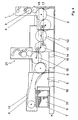
- the sheet-fed printing press shown in FIG. 1 has a modular, unit-type construction. It comprises a feeder (not shown), a delivery 5 for storing printed and / or varnished sheets and a plurality of printing units 1 arranged between feeder and delivery 5.
- the printing units 1 have a printing form cylinder 3 interacting with the printing cylinder 2 via the blanket cylinder 4 and an in Sheet conveying direction on this downstream further sheet-guiding cylinder and each apply a printing ink to the sheets separated by the feeder.
- the last printing unit 1 in the sheet conveying direction is directly connected to the delivery 5.
- the boom 5 is constructed in a known manner and has front and rear sprockets 6 arranged in pairs, over which conveyor chains 10 carrying gripper carriages 8 run.
- a stack carrier 20 is arranged, on which the printed and / or lacquered sheets are stacked to form a delivery stack 9.
- the stack carrier 20 is carried by stack lifting chains 7, which lower it step by step as the delivery stack grows during production until the maximum stack height is reached.
- the feeder, the printing units 1 and the delivery unit 5 are arranged in a set-up level, so that the sheets are transferred between adjacent sheet-guiding cylinders of various printing units 1 and from the last printing unit 1 in the sheet conveying direction to the gripper carriage 8 of the delivery unit 5 at a first level 17.
- the stacking space available in this arrangement for receiving the delivery stack 9 is usually sufficient for the processing of paper, which can only be stacked up in stacks with a comparatively small stacking height in order to limit the compressive stress on the lower sheets.
- FIG. 2 shows the sheet printing machine in a configuration for the handling of cardboard, in which the stacking space in the boom 5 and thus also the stacking capacity of the boom stack 9 is enlarged.
- a sheet conveying module 12 is arranged between the last printing unit 1 in the sheet conveying direction and the delivery 5.
- This comprises a sheet conveying device 13 designed as a sheet guide drum, which is followed by a first sheet guide cylinder 14.
- the sheet guide drum takes over the sheets from a sheet-guiding cylinder of the printing unit 1 in front of it at a first level 17. If the delivery 5, as shown in FIG. 1, is directly connected to a printing unit 1, the sheet is transferred on the first level 17 between the sheet-guiding cylinder of the printing unit 1 and the gripper carriage 8.
- the sheet conveying module 12 transfers the sheets to a second level 18, which is higher than the first, where the transfer to the gripper wagons 8 of the delivery 5 takes place, which is increased by the amount X to adapt to the second level 18 while increasing the stacking space.
- a frame elevation 16 is provided, which can be arranged below the boom 5.
- the cylinder angle that is decisive when the sheet is transferred to the sheet conveying module 12 is equal to the cylinder angle when the sheet is transferred from the sheet conveying module 12 to a subordinate unit.
- the first sheet-guiding cylinder 14 is rotated by the angle b relative to the sheet-conveying device 13 designed as a sheet-guiding drum.
- FIG. 3 and 4 show an embodiment of the invention using the example of a sheet printing machine
- the boom 5 a second sheet guide cylinder 15 and a delivery printing / coating unit 21 comprises, the printing cylinder forms the second sheet guide cylinder 15.
- the printing / coating units 1 upstream of the delivery arm 5 each have a printing cylinder 2, which is followed by a sheet-guiding cylinder.
- the boom 5 is either directly (Fig. 3) or with the interposition of the sheet conveyor module 12 (Fig. 4) with a Printing / coating unit 1 designed to be connectable in the manner described.
- dryers 11 are assigned to the sheet conveying module 12 and act as radiation dryers and hot air dryer are formed.
Landscapes
- Engineering & Computer Science (AREA)
- Mechanical Engineering (AREA)
- Supply, Installation And Extraction Of Printed Sheets Or Plates (AREA)
- Feeding Of Articles By Means Other Than Belts Or Rollers (AREA)
Abstract
Description
Man unterscheidet innerhalb einer Baureihe zumeist zwischen Druckmaschinenkonfigurationen mit sogenannten Normalstapelauslegern und Hochstapelauslegern. Während erstere bevorzugt beim Bedrucken von Papier Verwendung finden, werden letztere insbesondere beim Bedrucken von Kartonbogen verwendet, die auf Grund ihrer geringen Dichte zu hohen Stapeln aufgestapelt werden können, wobei die unteren Bogen des Stapels nur vergleichsweise geringen Druckkräfte ausgesetzt sind.
Die genannten Auslegerbauformen gleichen sich in ihrem grundsätzlichen Aufbau. Die Höhe der Gestellwände und die Länge der Führungsbahnen der umlaufenden Bogentransportsysteme unterscheidet sich jedoch bei den beiden Bauformen.
Nachteilig ist daran, dass mehrere Auslegertypen benötigt werden und dass zur Erhöhung der Stapelkapazität stets der gesamte Ausleger ausgetauscht werden muss.
Der Nachteil dieser Lösung besteht darin, dass die Ausbildung eines Podestes für die gesamte Maschine sehr kostenintensiv ist, zumal die erhöhten Aggregate durch eine sich längs der Druckmaschine erstreckende zusätzliche Galerie zugänglich gemacht werden müssen.
Eine weiterer Vorteil der Erfindung besteht darin, dass sie auch in den Fällen, in denen keine Grube zur Aufnahme des Auslegerstapels ausbildbar ist, eine Vergrößerung der Stapelkapazität des Auslegers ermöglicht. Die erreichbare Stapelkapazität wird in diesen Fällen nicht durch die Bauform des Auslegers vorgegeben und kann im Bedarfsfall auch über die Stapelkapazität eines bekannten Hochstapelauslegers hinausgehen. Das wird durch die Anordnung mehrerer Bogenfördermodule vor dem Ausleger ermöglicht.
Im zusammengefügten Zustand sind die Verbindungslinien der Mittelpunkte von miteinander zusammenwirkenden, in Bogenlaufrichtung nacheinander angeordneten bogenführenden Zylindern unterschiedlicher Aggregate im gleichen Winkel (Zylinderwinkel) zur Horizontalen geneigt.
Das gilt auch, wenn die Bogenübergabe zwischen einem bogenführenden Zylinder und einem Kettenfördersystem erfolgt, wobei dann der Mittelpunkt der Kreisbahn, den die Greiferwagen des Kettenfördersystems im Umlenkbereich beschreiben, an die Stelle des Zylindermittelpunktes tritt.
- Fig. 1
- eine Bogendruckmaschine, deren Ausleger direkt mit einem Druck-/Lackwerk verbunden ist;
- Fig. 2
- eine Bogendruckmaschine, deren Ausleger unter Zwischenschaltung eines Bogenfördermoduls mit einem Druck-/Lackwerk verbunden ist;
- Fig. 3
- eine Bogendruckmaschine mit einem Ausleger, der ein Kettenfördersystem mit vorgelagertem Bogenführungszylinder und ein Auslagedruckwerk/-lackwerk umfasst und
- Fig. 4
- eine Bogendruckmaschine, deren Ausleger ein Auslagedruckwerk/-lackwerk umfasst und unter Zwischenschaltung eines Bogenfördermoduls mit einem Druck-/Lackwerk verbunden ist.
Der bei dieser Anordnung zur Aufnahme des Auslegerstapels 9 zur Verfügung stehende Stapelraum ist für die Verarbeitung von Papier zumeist ausreichend, das nur zu Stapeln mit vergleichsweise geringer Stapelhöhe aufgestapelt werden kann, um die Druckbeanspruchung der unteren Bogen zu begrenzen.
Die Bogenführungstrommel übernimmt die Bogen von einem bogenführenden Zylinder des ihr vorgelagerten Druckwerkes 1 auf einem ersten Niveau 17.
Ist der Ausleger 5, wie in Fig.1 dargestellt, direkt mit einem Druckwerk 1 verbunden, erfolgt auf dem ersten Niveau 17 die Bogenübergabe zwischen dem bogenführenden Zylinder des Druckwerks 1 und den Greiferwagen 8.
Der Bogenfördermodul 12 überführt die Bogen auf ein gegenüber dem ersten höheres zweites Niveau 18, wo die Übergabe an die Greiferwagen 8 des Auslegers 5 erfolgt, der zur Anpassung an das zweite Niveau 18 unter Vergrößerung des Stapelraums um den Betrag X erhöht angeordnet ist. Dazu ist eine Gestellerhöhung 16 vorgesehen, die unterhalb des Auslegers 5 angeordnet werden kann.
Der bei der Bogenübergabe an den Bogenfördermodul 12 maßgebliche Zylinderwinkel


- 1
- Druckwerk-/Lackwerk
- 2
- Druckzylinder
- 3
- Druckformzylinder
- 4
- Gummituchzylinder
- 5
- Ausleger
- 6
- Kettenrad
- 7
- Stapelhubkette
- 8
- Greiferwagen
- 9
- Auslegerstapel
- 10
- Förderkette
- 11
- Trockner
- 12
- Bogenfördermodul
- 13
- Bogenfördereinrichtung
- 14
- erster Bogenführungszylinder
- 15
- zweiter Bogenführungszylinder
- 16
- Gestellerhöhung
- 17
- erstes Niveau
- 18
- zweites Niveau
- 19 20
- Stapelträger
- 21
- Auslagedruck/Lackwerk
Claims (9)
- Bogenverarbeitende Maschine, insbesondere Bogendruckmaschine, mit mindestens einem Druck-/oder Lackwerk (1), einem Bogenfördermodul (12) und einem bedruckte und/oder lackierte Bogen in einem Stapelraum zu einem Auslegerstapel (9) ablegenden Ausleger (5), der sowohl direkt als auch unter Zwischenschaltung des Bogenfördermoduls (12) mit dem mindestens einen Druck-/oder Lackwerk (1) verbindbar ist, derart, dass das mindestens eine Druck-/oder Lackwerk (1) die Bogen auf einem ersten Niveau (17) an den direkt mit ihm verbundenen Ausleger (5) beziehungsweise bei Zwischenschaltung des Bogenfördermoduls (12) an diesen übergibt, dadurch gekennzeichnet, dass die Bogen von dem Bogenfördermodul (12) auf ein zweites, gegenüber dem ersten höheres zweites Niveau (18) überführbar und an den zur Anpassung an das zweite Niveau (18) unter Vergrößerung des Stapelraums erhöht anordenbaren Ausleger (5) übergebbar ist.
- Bogenverarbeitende Maschine nach Anspruch 1, dadurch gekennzeichnet, dass der Bogenfördermodul (12) eine Bogenfördereinrichtung (13) umfasst, der in Bogenförderrichtung ein erster Bogenführungszylinder (14) nachgeordnet ist.
- Bogenverarbeitende Maschine nach Anspruch 2, dadurch gekennzeichnet, dass die Bogenfördereinrichtung (13) als Bogenführungstrommel ausgebildet ist.
- Bogenverarbeitende Maschine nach Anspruch 2, dadurch gekennzeichnet, dass als Bogenfördereinrichtung (13) ein erstes Kettenfördersystem vorgesehen ist.
- Bogenverarbeitende Maschine nach Anspruch 1, dadurch gekennzeichnet, dass der Ausleger (5) einen zweiten Bogenführungszylinder (15), dem in Bogenlaufrichtung ein zweites Kettenfördersystem nachgeordnet ist, umfasst.
- Bogenverarbeitende Maschine nach Anspruch 5, dadurch gekennzeichnet, dass als zweiter Bogenführungszylinder (15) der Druckzylinder eines Auslagedruck/Lackwerkes (21) vorgesehen ist.
- Bogenverarbeitende Maschine nach einem der vorhergehenden Ansprüche, dadurch gekennzeichnet, dass dem Bogenfördermodul (12) eine Trocknungseinrichtung, eine Pudereinrichtung, eine Absaugeinrichtung, eine Stanzeinrichtung, eine Perforiereinrichtung, eine Nummeriereinrichtung, eine Schneideinrichtung, eine Rilleinrichtung oder eine Qualitätsüberwachungseinrichtung zugeordnet ist.
- Bogenverarbeitende Maschine nach einem der vorhergehenden Ansprüche, dadurch gekennzeichnet, dass eine zur Anpassung an das zweite Niveau (18) unterhalb des Auslegers anordenbare Gestellerhöhung (16) vorgesehen ist.
- Bogenverarbeitende Maschine nach einem der vorhergehenden Ansprüche, dadurch gekennzeichnet, dass der Ausleger (5) zur Anpassung an das erste beziehungsweise zweite Niveau (17, 18) höhenverstellbar ausgeführt ist.
Applications Claiming Priority (2)
| Application Number | Priority Date | Filing Date | Title |
|---|---|---|---|
| DE10257497A DE10257497B4 (de) | 2002-12-10 | 2002-12-10 | Bogenfördermodul und bogenverarbeitende Maschine |
| DE10257497 | 2002-12-10 |
Publications (2)
| Publication Number | Publication Date |
|---|---|
| EP1442880A1 true EP1442880A1 (de) | 2004-08-04 |
| EP1442880B1 EP1442880B1 (de) | 2006-06-28 |
Family
ID=32518862
Family Applications (1)
| Application Number | Title | Priority Date | Filing Date |
|---|---|---|---|
| EP03023047A Expired - Lifetime EP1442880B1 (de) | 2002-12-10 | 2003-10-14 | Bogenverarbeitende Maschine |
Country Status (2)
| Country | Link |
|---|---|
| EP (1) | EP1442880B1 (de) |
| DE (2) | DE10257497B4 (de) |
Cited By (1)
| Publication number | Priority date | Publication date | Assignee | Title |
|---|---|---|---|---|
| EP1880846A3 (de) * | 2006-07-18 | 2011-06-15 | Heidelberger Druckmaschinen AG | Bogenoffsetdruckmaschine |
Families Citing this family (1)
| Publication number | Priority date | Publication date | Assignee | Title |
|---|---|---|---|---|
| DE102006012330C5 (de) | 2006-03-17 | 2023-04-06 | manroland sheetfed GmbH | Bogendruckmaschine mit Nachverarbeitungseinheit |
Citations (5)
| Publication number | Priority date | Publication date | Assignee | Title |
|---|---|---|---|---|
| FR2126798A5 (de) * | 1971-02-10 | 1972-10-06 | Polygraph Leipzig | |
| US4854231A (en) * | 1987-04-14 | 1989-08-08 | Heidelberger Druckmaschinen Aktiengesellschaft | Sheet-fed rotary printing presses for multi-color printing |
| EP0771649A1 (de) * | 1995-10-26 | 1997-05-07 | MAN Roland Druckmaschinen AG | Ausleger für eine Bogenrotationsdruckmaschine |
| US5873309A (en) * | 1996-07-20 | 1999-02-23 | Heidelberger Druckmaschinen Aktiengesellschaft | Rotary printing machine with a device for treating the surface of sheets |
| US20020135123A1 (en) * | 2000-03-24 | 2002-09-26 | Albert Maul | Device for transporting a sheet for a rotary printing machine |
Family Cites Families (11)
| Publication number | Priority date | Publication date | Assignee | Title |
|---|---|---|---|---|
| CH583096A5 (en) * | 1975-02-28 | 1976-12-31 | Akiyama Katsuji | Multi-colour offset printing press - has printing rollers one third in dia. of counter pressure rollers |
| DE3015519A1 (de) * | 1980-04-23 | 1981-10-29 | M.A.N.- Roland Druckmaschinen AG, 6050 Offenbach | Bogenrotationsdruckmaschine mit mindestens einem druckwert |
| JPS6387234A (ja) * | 1986-10-01 | 1988-04-18 | J M Insatsu Kikai Kk | 両面多色刷りオフセツト印刷機の胴配列 |
| US5555804A (en) * | 1993-06-25 | 1996-09-17 | Akiyama Printing Machine Manufacturing Company Ltd. | Perfecting sheet rotary offset press |
| DE4403884C2 (de) * | 1994-02-08 | 2003-09-18 | Koenig & Bauer Ag | Bogenrotationsdruckmaschine |
| DE19538546A1 (de) * | 1995-07-18 | 1997-01-23 | Koenig & Bauer Albert Ag | Bogenoffsetrotationsdruckmaschine |
| DE19723146C2 (de) * | 1997-06-03 | 1999-11-18 | Koenig & Bauer Ag | Bogenweiche zur Unterstützung der Bogenführung |
| JPH1110828A (ja) * | 1997-06-20 | 1999-01-19 | J M Insatsu Kikai Kk | 両面多色刷りオフセット印刷機 |
| DE19756796A1 (de) * | 1997-12-19 | 1999-07-22 | Koenig & Bauer Ag | Verfahren zum Bedrucken von Bogen im Schön- und Widerdruck sowie Schöndruck |
| JP3427004B2 (ja) * | 1999-04-20 | 2003-07-14 | 三菱重工業株式会社 | 枚葉両面印刷機 |
| DE20006513U1 (de) * | 2000-04-08 | 2000-07-13 | MAN Roland Druckmaschinen AG, 63075 Offenbach | Bogen-Rotationsdruckmaschine |
-
2002
- 2002-12-10 DE DE10257497A patent/DE10257497B4/de not_active Expired - Fee Related
-
2003
- 2003-10-14 EP EP03023047A patent/EP1442880B1/de not_active Expired - Lifetime
- 2003-10-14 DE DE50304045T patent/DE50304045D1/de not_active Expired - Lifetime
Patent Citations (5)
| Publication number | Priority date | Publication date | Assignee | Title |
|---|---|---|---|---|
| FR2126798A5 (de) * | 1971-02-10 | 1972-10-06 | Polygraph Leipzig | |
| US4854231A (en) * | 1987-04-14 | 1989-08-08 | Heidelberger Druckmaschinen Aktiengesellschaft | Sheet-fed rotary printing presses for multi-color printing |
| EP0771649A1 (de) * | 1995-10-26 | 1997-05-07 | MAN Roland Druckmaschinen AG | Ausleger für eine Bogenrotationsdruckmaschine |
| US5873309A (en) * | 1996-07-20 | 1999-02-23 | Heidelberger Druckmaschinen Aktiengesellschaft | Rotary printing machine with a device for treating the surface of sheets |
| US20020135123A1 (en) * | 2000-03-24 | 2002-09-26 | Albert Maul | Device for transporting a sheet for a rotary printing machine |
Cited By (1)
| Publication number | Priority date | Publication date | Assignee | Title |
|---|---|---|---|---|
| EP1880846A3 (de) * | 2006-07-18 | 2011-06-15 | Heidelberger Druckmaschinen AG | Bogenoffsetdruckmaschine |
Also Published As
| Publication number | Publication date |
|---|---|
| DE10257497A1 (de) | 2004-07-15 |
| DE50304045D1 (de) | 2006-08-10 |
| DE10257497B4 (de) | 2008-02-21 |
| EP1442880B1 (de) | 2006-06-28 |
Similar Documents
| Publication | Publication Date | Title |
|---|---|---|
| EP1147893B2 (de) | Bogen-Rotationsdruckmaschine mit einem Multifunktionsmodul | |
| EP2006102B1 (de) | Rollendruckmaschinen zur Handhabung von Druckplatten | |
| DE19819490C1 (de) | Ausleger für eine Bogenrotationsdruckmaschine | |
| EP1392589B1 (de) | Auslagevorrichtung einer bogen verarbeitende maschine und verfahren zum auslegen von bogen in einer solchen maschine | |
| DE3612067C2 (de) | ||
| DE2547149C3 (de) | Stapelvorrichtung zur Beschickung einer Etagenpresse | |
| EP1878571A2 (de) | Druckeinheit einer Rotationsdruckmaschine | |
| DE69708534T2 (de) | Gerät zur Untersuchung von Blättern für eine Offsetbogendruckmaschine | |
| EP1352742B1 (de) | Verfahren zur Steuerung der Bogenzufuhr | |
| DE19711406C1 (de) | Verfahren und Vorrichtung zum Stapeln von Bögen, insbesondere von geschuppt zugeförderten Papier- oder Kartonbögen auf Paletten | |
| EP1442880B1 (de) | Bogenverarbeitende Maschine | |
| EP1326749A2 (de) | Bogendruckmaschine und von der maschine umgesetztes verfahren | |
| EP0755784A2 (de) | Bogendruckmaschine | |
| DE2614665A1 (de) | Falzapparat, innerhalb der druckwerksreihe plaziert, mit nach art von kassetten austauschbarem falzmechanismus | |
| EP0511528A1 (de) | Vorrichtung zur Entsorgung einer Bogendruckmaschine | |
| EP3851280A1 (de) | Vorrichtung zum handhaben von druckplatten an einer druckmaschine | |
| EP0805025B1 (de) | Druckgutfördervorrichtung zwischen Druckwerken | |
| CH651501A5 (en) | Sheet-fed rotary printing machine having at least one printing unit | |
| DE102016109947A1 (de) | Auslegevorrichtung an einer Bogenrotationsdruckmaschine | |
| EP1136409A2 (de) | Vorrichtung zum Abbremsen von Probe- und Fehlerbogen einer Bogen verarbeitenden Maschine | |
| DE10222543A1 (de) | Auslegevorrichtung an einer Bogenverarbeitungsmaschine | |
| DE69819579T2 (de) | Sortieranlage für keramische Gegenstände, insbesondere Ziegel, mit modulärer Verpackungsstation | |
| DE19914356C2 (de) | Folien-Legeanlage zum oberseitigen oder unterseitigen Belegen von Trägerplatten mit Folien | |
| EP1153745A1 (de) | Bogenrotationsdruckmaschine für Mehrfarbendruck | |
| DE4343618C2 (de) | Non-Stop-Anleger |
Legal Events
| Date | Code | Title | Description |
|---|---|---|---|
| PUAI | Public reference made under article 153(3) epc to a published international application that has entered the european phase |
Free format text: ORIGINAL CODE: 0009012 |
|
| 17P | Request for examination filed |
Effective date: 20040421 |
|
| AK | Designated contracting states |
Kind code of ref document: A1 Designated state(s): AT BE BG CH CY CZ DE DK EE ES FI FR GB GR HU IE IT LI LU MC NL PT RO SE SI SK TR |
|
| AX | Request for extension of the european patent |
Extension state: AL LT LV MK |
|
| AKX | Designation fees paid |
Designated state(s): DE FR GB IT |
|
| 17Q | First examination report despatched |
Effective date: 20050509 |
|
| RBV | Designated contracting states (corrected) |
Designated state(s): DE FR GB IT |
|
| GRAP | Despatch of communication of intention to grant a patent |
Free format text: ORIGINAL CODE: EPIDOSNIGR1 |
|
| GRAS | Grant fee paid |
Free format text: ORIGINAL CODE: EPIDOSNIGR3 |
|
| GRAA | (expected) grant |
Free format text: ORIGINAL CODE: 0009210 |
|
| AK | Designated contracting states |
Kind code of ref document: B1 Designated state(s): DE FR GB IT |
|
| PG25 | Lapsed in a contracting state [announced via postgrant information from national office to epo] |
Ref country code: IT Free format text: LAPSE BECAUSE OF FAILURE TO SUBMIT A TRANSLATION OF THE DESCRIPTION OR TO PAY THE FEE WITHIN THE PRESCRIBED TIME-LIMIT;WARNING: LAPSES OF ITALIAN PATENTS WITH EFFECTIVE DATE BEFORE 2007 MAY HAVE OCCURRED AT ANY TIME BEFORE 2007. THE CORRECT EFFECTIVE DATE MAY BE DIFFERENT FROM THE ONE RECORDED. Effective date: 20060628 |
|
| REG | Reference to a national code |
Ref country code: GB Ref legal event code: FG4D Free format text: NOT ENGLISH |
|
| REF | Corresponds to: |
Ref document number: 50304045 Country of ref document: DE Date of ref document: 20060810 Kind code of ref document: P |
|
| GBT | Gb: translation of ep patent filed (gb section 77(6)(a)/1977) |
Effective date: 20061002 |
|
| ET | Fr: translation filed | ||
| PLBE | No opposition filed within time limit |
Free format text: ORIGINAL CODE: 0009261 |
|
| STAA | Information on the status of an ep patent application or granted ep patent |
Free format text: STATUS: NO OPPOSITION FILED WITHIN TIME LIMIT |
|
| 26N | No opposition filed |
Effective date: 20070329 |
|
| PGFP | Annual fee paid to national office [announced via postgrant information from national office to epo] |
Ref country code: GB Payment date: 20131021 Year of fee payment: 11 Ref country code: FR Payment date: 20131022 Year of fee payment: 11 |
|
| PGFP | Annual fee paid to national office [announced via postgrant information from national office to epo] |
Ref country code: IT Payment date: 20131024 Year of fee payment: 11 |
|
| GBPC | Gb: european patent ceased through non-payment of renewal fee |
Effective date: 20141014 |
|
| PG25 | Lapsed in a contracting state [announced via postgrant information from national office to epo] |
Ref country code: GB Free format text: LAPSE BECAUSE OF NON-PAYMENT OF DUE FEES Effective date: 20141014 |
|
| REG | Reference to a national code |
Ref country code: FR Ref legal event code: ST Effective date: 20150630 |
|
| REG | Reference to a national code |
Ref country code: DE Ref legal event code: R081 Ref document number: 50304045 Country of ref document: DE Owner name: KOENIG & BAUER AG, DE Free format text: FORMER OWNER: KOENIG & BAUER AKTIENGESELLSCHAFT, 97080 WUERZBURG, DE |
|
| PG25 | Lapsed in a contracting state [announced via postgrant information from national office to epo] |
Ref country code: FR Free format text: LAPSE BECAUSE OF NON-PAYMENT OF DUE FEES Effective date: 20141031 Ref country code: IT Free format text: LAPSE BECAUSE OF NON-PAYMENT OF DUE FEES Effective date: 20141014 |
|
| PGFP | Annual fee paid to national office [announced via postgrant information from national office to epo] |
Ref country code: DE Payment date: 20191108 Year of fee payment: 17 |
|
| REG | Reference to a national code |
Ref country code: DE Ref legal event code: R119 Ref document number: 50304045 Country of ref document: DE |
|
| PG25 | Lapsed in a contracting state [announced via postgrant information from national office to epo] |
Ref country code: DE Free format text: LAPSE BECAUSE OF NON-PAYMENT OF DUE FEES Effective date: 20210501 |