EP1440218B1 - Antrieb - Google Patents
Antrieb Download PDFInfo
- Publication number
- EP1440218B1 EP1440218B1 EP02774725.2A EP02774725A EP1440218B1 EP 1440218 B1 EP1440218 B1 EP 1440218B1 EP 02774725 A EP02774725 A EP 02774725A EP 1440218 B1 EP1440218 B1 EP 1440218B1
- Authority
- EP
- European Patent Office
- Prior art keywords
- drive
- hinge
- lever
- rotationally fixed
- fixed manner
- Prior art date
- Legal status (The legal status is an assumption and is not a legal conclusion. Google has not performed a legal analysis and makes no representation as to the accuracy of the status listed.)
- Expired - Lifetime
Links
Images

Classifications
-
- E—FIXED CONSTRUCTIONS
- E05—LOCKS; KEYS; WINDOW OR DOOR FITTINGS; SAFES
- E05F—DEVICES FOR MOVING WINGS INTO OPEN OR CLOSED POSITION; CHECKS FOR WINGS; WING FITTINGS NOT OTHERWISE PROVIDED FOR, CONCERNED WITH THE FUNCTIONING OF THE WING
- E05F15/00—Power-operated mechanisms for wings
- E05F15/60—Power-operated mechanisms for wings using electrical actuators
- E05F15/603—Power-operated mechanisms for wings using electrical actuators using rotary electromotors
- E05F15/611—Power-operated mechanisms for wings using electrical actuators using rotary electromotors for swinging wings
- E05F15/63—Power-operated mechanisms for wings using electrical actuators using rotary electromotors for swinging wings operated by swinging arms
-
- E—FIXED CONSTRUCTIONS
- E05—LOCKS; KEYS; WINDOW OR DOOR FITTINGS; SAFES
- E05F—DEVICES FOR MOVING WINGS INTO OPEN OR CLOSED POSITION; CHECKS FOR WINGS; WING FITTINGS NOT OTHERWISE PROVIDED FOR, CONCERNED WITH THE FUNCTIONING OF THE WING
- E05F15/00—Power-operated mechanisms for wings
- E05F15/60—Power-operated mechanisms for wings using electrical actuators
- E05F15/603—Power-operated mechanisms for wings using electrical actuators using rotary electromotors
- E05F15/611—Power-operated mechanisms for wings using electrical actuators using rotary electromotors for swinging wings
- E05F15/614—Power-operated mechanisms for wings using electrical actuators using rotary electromotors for swinging wings operated by meshing gear wheels, one of which being mounted at the wing pivot axis; operated by a motor acting directly on the wing pivot axis
-
- E—FIXED CONSTRUCTIONS
- E05—LOCKS; KEYS; WINDOW OR DOOR FITTINGS; SAFES
- E05Y—INDEXING SCHEME ASSOCIATED WITH SUBCLASSES E05D AND E05F, RELATING TO CONSTRUCTION ELEMENTS, ELECTRIC CONTROL, POWER SUPPLY, POWER SIGNAL OR TRANSMISSION, USER INTERFACES, MOUNTING OR COUPLING, DETAILS, ACCESSORIES, AUXILIARY OPERATIONS NOT OTHERWISE PROVIDED FOR, APPLICATION THEREOF
- E05Y2900/00—Application of doors, windows, wings or fittings thereof
- E05Y2900/50—Application of doors, windows, wings or fittings thereof for vehicles
- E05Y2900/53—Type of wing
- E05Y2900/531—Doors
-
- E—FIXED CONSTRUCTIONS
- E05—LOCKS; KEYS; WINDOW OR DOOR FITTINGS; SAFES
- E05Y—INDEXING SCHEME ASSOCIATED WITH SUBCLASSES E05D AND E05F, RELATING TO CONSTRUCTION ELEMENTS, ELECTRIC CONTROL, POWER SUPPLY, POWER SIGNAL OR TRANSMISSION, USER INTERFACES, MOUNTING OR COUPLING, DETAILS, ACCESSORIES, AUXILIARY OPERATIONS NOT OTHERWISE PROVIDED FOR, APPLICATION THEREOF
- E05Y2900/00—Application of doors, windows, wings or fittings thereof
- E05Y2900/50—Application of doors, windows, wings or fittings thereof for vehicles
- E05Y2900/53—Type of wing
- E05Y2900/536—Hoods
-
- E—FIXED CONSTRUCTIONS
- E05—LOCKS; KEYS; WINDOW OR DOOR FITTINGS; SAFES
- E05Y—INDEXING SCHEME ASSOCIATED WITH SUBCLASSES E05D AND E05F, RELATING TO CONSTRUCTION ELEMENTS, ELECTRIC CONTROL, POWER SUPPLY, POWER SIGNAL OR TRANSMISSION, USER INTERFACES, MOUNTING OR COUPLING, DETAILS, ACCESSORIES, AUXILIARY OPERATIONS NOT OTHERWISE PROVIDED FOR, APPLICATION THEREOF
- E05Y2900/00—Application of doors, windows, wings or fittings thereof
- E05Y2900/50—Application of doors, windows, wings or fittings thereof for vehicles
- E05Y2900/53—Type of wing
- E05Y2900/548—Trunk lids
Definitions
- the invention relates to a drive for pivoting a gel with a hinge strap rotatably connected vehicle door or vehicle door (tailgate, hood, etc.).
- German patent application 101 17 933.2 is a motor vehicle with automatically lockable vehicle door or vehicle door (hereinafter also referred to collectively only as a vehicle door) known in which the vehicle door can be closed or opened by a corresponding actuation of a switch provided in the instrument panel.
- the switching signal generated by the switch acts on an electronic control device, which in turn generates electrical control signals for activating an electric motor, which then in turn acts via a downstream transmission on a lever-shaped extension of the hinge bracket and pivots or shifts the vehicle door.
- a drive is also bekant from the prepublished German patent application 197 44 908 A1 ,
- the hinge bracket must be provided with an additional lever-shaped part.
- the drive is constructed relatively space consuming.
- the part of the drive, which is connected to the hinge bracket often visible to a third party when the lever-shaped extension of the hinge bracket is not throughout its pivoting to open the tailgate, etc. within the headliner of the corresponding motor vehicle.
- the invention has for its object to provide a space-saving drive of the type mentioned, in which the coupling between the drive and the hinge bracket in a simple manner and possible for a third person invisible can be arranged.
- the invention is based essentially on the idea not to connect the drive with an additional lever-shaped part of the hinge bracket, but directly on the non-rotatably connected to the hinge bracket and, for example. acting in the headliner of the corresponding motor vehicle hinge axis.
- the corresponding hinges including the hinge axis with hinge bracket are attached on the not yet surface-treated body of the vehicle and to install the drive, if desired, only later in the otherwise finished vehicle. Since the drive according to the invention is usually connected laterally from the hinge with hinge axis, the corresponding hinge axis must optionally be led out laterally from the hinge or extended.
- a lever mechanism In order to enable a good power transmission with a relatively small footprint, the use of a lever mechanism has proven to be advantageous as a transmission for pivoting the hinge axis, wherein a drive lever with the motor and an output lever with the hinge axis are rotatably connected and wherein the two levers via at least one - preferably two symmetrically arranged - coupling rod (s) are hinged together.
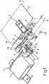
- Fig.1 1 is a drive for pivoting a with a hinge bracket 2 rotatably connected, indicated by dashed lines the tailgate 3 of a motor vehicle.
- the hinge bracket 2 is rotatably connected to a hinge axis 4, which is pivotally mounted on a hinge 5.
- the hinge 5 is attached to the likewise indicated by dashed lines body 6 of the corresponding vehicle.
- the drive 1 comprises an electric motor 7, which is also secured via a flange 8 to the body of the vehicle, and aeuernes with the electric motor 7 lever mechanism 9.
- the lever mechanism 9 has a drive lever 10 which is connected to the output shaft 11 of the electric motor 7 (Fig. or an intermediate gear in the case of a geared motor) is rotatably connected.
- the lever mechanism 9 comprises a driven lever 12 which is rotatably connected to the laterally over the hinge 5 protruding hinge axis 4 via a positive connection (for example, splines).
- the drive lever 10 and the output lever 12 of the lever mechanism 9 are connected via two coupling rods 13, 14 hinged together.
- the coupling rods 13, 14 via joint bearings 15, 16 attached to the levers 10, 12 to compensate for tolerances between the output shaft 11 of the electric motor 7 and the hinge axis 4.
- the lever mechanism 9 is covered in the intended use of the drive 1 by a housing 17 ( Fig.2 ), on which a hinge bearing 18 is arranged, in which the hinge axis 4 is pivotally mounted, so that the drive 1 is centered with respect to the hinge axis 4. Behind the pivot bearing 18 is a likewise attached to the housing 17 angle encoder 19 which is rotatably connected to the hinge axis 4 and serves to position the tailgate 3.
- a receptacle 20 for a on the Hinge 5 fixed rod-shaped support member 21 is provided, which serves for the angular support of the drive 1.
- the electric motor 7 via a corresponding circuit device (not shown) is activated.
- the output shaft 11 of the electric motor 7 then rotates counterclockwise in the direction of the arrow labeled 22.
- the drive lever 10 is pivoted downward and takes over the coupling rods 13, 14 the output lever 12 with. This then also rotates the hinge axis 4 in the counterclockwise direction.
- the tailgate opens up to a predetermined position, in which the angle sensor 19 switches off the electric motor 7 directly or via the circuit device, not shown.
- the invention is not limited to the embodiment described above. So it must not necessarily be a Hebei- or crank gear in the transmission, but it can also be used, for example, a gear transmission.
- the engine may also be a hydraulically or pneumatically driven engine.
- housing 17 may also be part of a housing comprising the entire drive 1.
Landscapes
- Power-Operated Mechanisms For Wings (AREA)
Description
- Die Erfindung betrifft einen Antrieb zum Verschwenken einer mit einem Scharnierbü- gel drehfest verbundenen Fahrzeugtür oder Fahrzeugklappe (Heckklappe, Motorhaube etc.).
- Aus der nicht vorveröffentlichten deutschen Patentanmeldung
101 17 933.2 ist ein Kraftfahrzeug mit automatisch verschliessbarer Fahrzeugtür oder Fahrzeugklappe (im folgenden auch zusammenfassend nur als Fahrzeugtür bezeichnet) bekannt, bei dem durch eine entsprechende Betätigung eines in der Instrumententafel vorgesehenen Schalters die Fahrzeugtür geschlossen oder geöffnet werden kann. Hierzu wirkt das von dem Schalter erzeugte Schaltsignal auf eine elektronische Steuereinrichtung, die ihrerseits elektrische Steuersignale zur Aktivierung eines Elektromotors erzeugt, der dann seinerseits über ein nachgeschaltetes Getriebe auf eine hebelförmige Verlängerung des Scharnierbügels einwirkt und die Fahrzeugtür verschwenkt oder verschiebt. - Ein Antrieb ist auch bekant aus der vorveröffentlichten deutschen Patentanmeldung
197 44 908 A1 . - Nachteilig ist bei diesem Kraftfahrzeug unter anderem, dass der Scharnierbügel mit einem zusätzlichen hebelförmigen Teil versehen werden muss. Ausserdem ist der Antrieb relativ platzaufwendig aufgebaut. Schliesslich ist der Teil des Antriebes, der mit dem Scharnierbügel verbunden ist, häufig für einen Dritten sichtbar, wenn sich die hebelförmige Verlängerung des Scharnierbügels nicht während ihres gesamten Schwenkweges zum Öffnen der Heckklappe etc. innerhalb des Dachhimmels des entsprechenden Kraftfahrzeuges befindet.
- Der Erfindung liegt die Aufgabe zugrunde, einen platzsparend aufgebauten Antrieb der eingangs erwähnten Art anzugeben, bei dem die Kopplung zwischen dem Antrieb und dem Scharnierbügel auf einfache Weise und möglichst für einen Dritten unsichtbar anordbar ist.
- Diese Aufgabe wird erfindungsgemäss durch die Merkmale des Anspruchs 1 gelöst.
- Weitere, besonders vorteilhafte Ausgestaltungen der Erfindung offenbaren die Unterensprüche.
- Die Erfindung beruht im wesentlichen auf dem Gedanken, den Antrieb nicht mit einem zusätzlichen hebelförmigen Teil des Scharnierbügels zu verbinden, sondern direkt auf die mit dem Scharnierbügel drehfest verbundene und z.B. im Dachhimmel des entsprechenden Kraftfahrzeuges liegende Scharnierachse einzuwirken.
- Bei Verwendung des erfindungsgemäßen Antriebes ist es in vorteilhafter Weise möglich, die entsprechenden Scharniere einschließlich der Scharnierachse mit Scharnierbügel an der noch nicht oberflächenbehandelten Karosserie des Fahrzeuges zu befestigen und den Antrieb, falls gewünscht, erst später in das ansonsten fertige Fahrzeug einzubauen. Da der erfindungsgemäße Antrieb üblicherweise seitlich von dem Scharnier mit Scharnierachse verbunden wird, muß die entsprechende Scharnierachse gegebenenfalls seitlich aus dem Scharnier herausgeführt bzw. verlängert werden.
- Um eine gute Kraftübertragung bei relativ geringem Platzbedarf zu ermöglichen, hat sich als Getriebe für das Verschwenken der Scharnierachse vor allem die Verwendung eines Hebelgetriebes als vorteilhaft erwiesen, wobei ein Antriebshebel mit dem Motor und ein Abtriebshebel mit der Scharnierachse drehfest verbunden sind und wobei die beiden Hebel über mindestens eine -vorzugsweise zwei symmetrisch zueinander angeordnete- Kupplungsstange(n) gelenkig miteinander verbunden sind.
- Zum Ausgleich von Koaxialitätstoleranzen zwischen der Antriebswelle und der Scharnierachse hat es sich als zweckmäßig erwiesen, die Kupplungsstangen über Gelenklager an den Hebeln zu befestigen, so daß Taumelbewegungen bis zu 5° um den Hauptbefestigungspunkt an der Scharnierachse möglich sind.
- Weitere Einzelheiten und Vorteile der Erfindung ergeben sich aus den folgenden anhand von Figuren erläuterten Ausführungsbeispielen. Es zeigen:
-
Fig.1 die perspektivische Darstellung eines erfindungsgemäßen Antriebes mit Hebelgetriebe ohne Getriebegehäuse und -
Fig.2 eineFig. 1 entsprechende Darstellung, bei welcher das Hebelgetriebe mit einem Getriebegehäuse versehen ist. - In den
Fig.1 ist mit 1 ein Antrieb zum Verschwenken einer mit einem Scharnierbügel 2 drehfest verbundenen, gestrichelt angedeuteten Heckklappe 3 eines Kraftfahrzeuges bezeichnet. Der Scharnierbügel 2 ist drehfest mit einer Scharnierachse 4 verbunden, welche schwenkbar an einem Scharnier 5 angeordnet ist. Das Scharnier 5 ist an der ebenfalls gestrichelt angedeuteten Karosserie 6 des entsprechenden Fahrzeuges befestigt. - Der Antrieb 1 umfaßt einen Elektromotor 7, welcher ebenfalls über einen Flansch 8 an der Karosserie des Fahrzeuges befestigt ist, und ein mit dem Elektromotor 7 verbundennes Hebelgetriebe 9. Das Hebelgetriebe 9 weist einen Antriebshebel 10 auf, welcher mit der Abtriebswelle 11 des Elektromotors 7 (oder eines Zwischengetriebes im Falle eines Getriebemotors) drehfest verbunden ist. Außerdem umfaßt das Hebelgetriebe 9 einen Abtriebshebel 12, der mit der seitlich über das Scharnier 5 hervorstehenden Scharnierachse 4 über eine Formschlußverbindung (z.B. Keilverzahnung) drehfest verbunden ist. Der Antriebshebel 10 und der Abtriebshebel 12 des Hebelgetriebes 9 sind über zwei Kupplungsstangen 13, 14 miteinander gelenkig verbunden. Dabei sind die Kupplungsstangen 13, 14 über Gelenklager 15, 16 an den Hebeln 10, 12 befestigt, um Toleranzen zwischen der Abtriebswelle 11 des Elektromotors 7 und der Scharnierachse 4 auszugleichen.
- Das Hebelgetriebe 9 wird bei der bestimmungsgemäßen Verwendung des Antriebes 1 durch ein Gehäuse 17 abgedeckt (
Fig.2 ), an dem ein Gelenklager 18 angeordnet ist, in welchem die Scharnierachse 4 schwenkbar gelagert ist, so daß der Antrieb 1 in bezug auf die Scharnierachse 4 zentriert wird. Hinter dem Gelenklager 18 befindet sich ein ebenfalls an dem Gehäuse 17 befestigter Winkelgeber 19, der drehfest mit der Scharnierachse 4 verbunden ist und zur Positionsbestimmung der Heckklappe 3 dient. - Ferner ist an dem Gehäuse 17 des Hebelgetriebes 9 eine Aufnahme 20 für ein an dem Scharnier 5 befestigtes stangenförmiges Abstützelement 21 vorgesehen, welches zur Winkelabstützung des Antriebes 1 dient.
- Soll die Heckklappe 3 beispielsweise aus der in
Fig.1 dargestellten Position nach oben verschwenkt werden, so wird der Elektromotor 7 über eine entsprechende Schaltungsvorrichtung (nicht dargestellt) aktiviert. Die Abtriebswelle 11 des Elektromotors 7 dreht sich dann in Richtung des mit 22 bezeichneten Pfeiles entgegen dem Uhrzeigersinn. Der Antriebshebel 10 wird nach unten geschwenkt und nimmt über die Kupplungsstangen 13, 14 den Abtriebshebel 12 mit. Dieser dreht dann auch die Scharnierachse 4 entgegen dem Uhrzeigersinn. Die Heckklappe öffnet sich bis zu einer vorgegebenen Position, bei welcher der Winkelgeber 19 den Elektromotor 7 direkt oder über die nicht dargestellte Schaltungsvorrichtung abschaltet. - Die Erfindung ist selbstverständlich nicht auf das vorstehend beschriebene Ausführungsbeispiel beschränkt. So muß es sich bei dem Getriebe nicht zwingend um ein Hebei- bzw. Kurbelgetriebe handeln, sondern es kann auch beispielsweise ein Zahnradgetriebe verwendet werden.
- Ferner können zur Befestigung der Kupplungsstangen 13, 14 an den Hebeln 10, 12 statt Gelenklager z.B. auch Nadellager verwendet werden, wenn nur kleinere Toleranzen zwischen der Abtriebswelle 11 und der Scharnierachse 4 zu berücksichtigen sind.
- Bei dem Motor kann es sich auch um einen hydraulisch oder pneumatisch angetriebenen Motor handeln.
- Schließlich kann das Gehäuse 17 auch Teil eines den gesamten Antrieb 1 umfassenden Gehäuses sein.
-
- 1
- Antrieb
- 2
- Scharnierbügel
- 3
- Heckklappe, Fahrzeugklappe
- 4
- Scharnierachse
- 5
- Scharnier
- 6
- Karosserie
- 7
- Elektromotor, Motor
- 8
- Flansch
- 9
- Hebelgetriebe, Getriebe
- 10
- Antriebshebel, Hebel
- 11
- Abtriebswelle
- 12
- Abtriebshebel
- 13,14
- Kupplungsstangen
- 15, 16
- Gelenklager
- 17
- Gehäuse
- 18
- -Gelenklager
- 19
- Winkelgeber
- 20
- Aufnahme
- 21
- Abstützelement
- 22
- Pfeil
Claims (4)
- Antrieb zum Verschwenken einer mit einem Scharnierbügel (2) drehfest verbundenen Fahrzeugtür oder Fahrzeugklappe (3) mit den Merkmalen :a) der Antrieb (1) umfasst einen Motor (7) und ein diesem nachgeschaltetes Getriebe (9), welches auf den mit einer Scharnierachse (4) drehfest verbundenen Scharnierbügel (2) wirkt;
die Scharnierachse (4) wirkt im Dachhimmel des entsprechenden Kraftfahrzeuges liegende Scharnierachse ein ;b) das Getriebe (9) ist abtriebsseitig mit der Scharnierachse (4) drehfest verbunden,wobei der Antrieb (1) ein Gelenklager (18) umfasst, in welchem das dem Antrieb (1) zugewandte Ende der Scharnierachse (4) schwenkbar lagerbar ist, und/oder der Antrieb (1) einen drehfest mit der Scharnierachse (4) verbindbaren Winkelgeber (19) umfasst,
dadurch gekennzeichnet, dass es sich bei dem Getriebe (9) um ein Hebelgetriebe handelt, wobei ein Antriebshebel (10) mit dem Motor (7) und ein Abtriebshebel (12) mit der Scharnierachse (4) drehfest verbunden sind und wobei die beiden Hebel (10,12) über mindestens eine Kupplungsstange (13,14) gelenkig miteinander verbunden sind,
wobei der Antrieb (1) ein Gehäuse (17) umfasst, an dem über Befestigungsteile das Gelenklager (18), und/oder der Winkelgeber (19), befestigt ist, und wobei an dem Gehäuse (17) eine Aufnahme (20) für ein an dem Scharnier (5) befestigtes stangenförmiges Abstützelement (21) vorgesehen ist. - Antrieb nach Anspruch 1, dadurch gekennzeichnet, dass der Antriebshebel (10) und der Abtriebshebel (12) durch zwei, auf beiden Seiten der Hebel (10,12) sym- metrisch zueinander angeordneten Kupplungsstangen (13,14) miteinander gelenkig verbunden sind.
- Antrieb nach Anspruch 1 oder 2, dadurch gekennzeichnet, dass die Kupplungs- stangen (13,14) über Gelenklager (15,16) an dem Antriebshebel (10) und an dem Abtriebshebel (12) befestigt sind.
- Antrieb nach einem der Ansprüche 1 bis 3, dadurch gekennzeichnet, dass der Abtriebshebel (12) formschlüssig mit der Scharnierachse (4) verbindbar ist.
Applications Claiming Priority (3)
| Application Number | Priority Date | Filing Date | Title |
|---|---|---|---|
| DE10152696A DE10152696B4 (de) | 2001-10-19 | 2001-10-19 | Antrieb |
| DE10152696 | 2001-10-19 | ||
| PCT/EP2002/011616 WO2003036008A1 (de) | 2001-10-19 | 2002-10-17 | Antrieb |
Publications (2)
| Publication Number | Publication Date |
|---|---|
| EP1440218A1 EP1440218A1 (de) | 2004-07-28 |
| EP1440218B1 true EP1440218B1 (de) | 2016-04-27 |
Family
ID=7703691
Family Applications (1)
| Application Number | Title | Priority Date | Filing Date |
|---|---|---|---|
| EP02774725.2A Expired - Lifetime EP1440218B1 (de) | 2001-10-19 | 2002-10-17 | Antrieb |
Country Status (5)
| Country | Link |
|---|---|
| US (1) | US20040244294A1 (de) |
| EP (1) | EP1440218B1 (de) |
| JP (1) | JP2005506481A (de) |
| DE (1) | DE10152696B4 (de) |
| WO (1) | WO2003036008A1 (de) |
Families Citing this family (11)
| Publication number | Priority date | Publication date | Assignee | Title |
|---|---|---|---|---|
| DE10222298B4 (de) * | 2002-05-18 | 2010-11-11 | Valeo Sicherheitssysteme Gmbh | Vorrichtung zum Verschwenken einer Fahrzeugtür oder Fahrzeugklappe |
| DE10222290B4 (de) * | 2002-05-18 | 2010-11-11 | Valeo Sicherheitssysteme Gmbh | Antrieb |
| JP5112686B2 (ja) * | 2003-01-22 | 2013-01-09 | エドゥシャ アーゲー | ヒンジ |
| DE102005061978B3 (de) * | 2005-12-23 | 2007-02-08 | Audi Ag | Scharniervorrichtung |
| FR2906501B1 (fr) * | 2006-10-03 | 2010-05-14 | Plastic Omnium Cie | Ouvrant arriere destine a etre rapporte sur un vehicule automobile, ensemble de deux ouvrants arriere. |
| US9540859B2 (en) | 2014-06-16 | 2017-01-10 | Strattec Power Access Llc | Power closure system |
| JP6583685B2 (ja) * | 2016-01-21 | 2019-10-02 | 三井金属アクト株式会社 | ドア開閉装置 |
| DE102016210168B3 (de) * | 2016-06-09 | 2017-04-13 | Bayerische Motoren Werke Aktiengesellschaft | Türantrieb für eine Kraftwagentür |
| US20190368255A1 (en) * | 2018-06-04 | 2019-12-05 | Magna Closures Inc. | Hinge based counterbalance mechanism |
| DE102019128986A1 (de) * | 2018-10-29 | 2020-05-20 | Magna Closures Inc. | Kraft-betätigungsmechanismus zur betätigung eines verschlusspaneels eines fahrzeugs |
| EP4067613B1 (de) * | 2021-03-30 | 2026-02-18 | Ratier-Figeac SAS | Vorrichtung zur unterstützung der türöffnung |
Family Cites Families (16)
| Publication number | Priority date | Publication date | Assignee | Title |
|---|---|---|---|---|
| US2795414A (en) * | 1953-07-03 | 1957-06-11 | Productive Inventions Inc | Window operating device |
| US3084927A (en) * | 1960-02-15 | 1963-04-09 | Crown Ind Inc | Automatic door operator |
| US3247615A (en) * | 1963-12-10 | 1966-04-26 | Stanley Works | Electrical control circuit for electromechanical door operator |
| US3333362A (en) * | 1965-02-05 | 1967-08-01 | Ford Motor Co | Convertible backlight |
| US3622197A (en) * | 1969-09-25 | 1971-11-23 | Gen Motors Corp | Vehicle body closure |
| US3864875A (en) * | 1973-04-16 | 1975-02-11 | Overhead Door Corp | Swing door operator |
| US3874117A (en) * | 1973-09-28 | 1975-04-01 | R H Boehm Company Inc | Electric door opener |
| DE2431747C2 (de) * | 1974-07-02 | 1981-09-17 | Linke-Hofmann-Busch, Waggon-Fahrzeug-Maschinen Gmbh, 3320 Salzgitter | Mechanische Betätigung für zwei Türflügel von Dreh-, Falt- oder Schwingtüren für Straßen- oder Schienenfahrzeuge |
| US4454685A (en) * | 1979-06-20 | 1984-06-19 | Tebel Machinefabrieken B.V. | Vehicle door construction |
| DE3016174A1 (de) * | 1980-04-26 | 1981-11-05 | Gebr. Bode & Co, 3500 Kassel | Antriebsvorrichtung fuer den tuerfluegel einer fahrzeugtuer |
| US4398419A (en) * | 1980-08-29 | 1983-08-16 | Aisin Seiki Company, Limited | Rotational angle sensor |
| US5412908A (en) * | 1993-04-08 | 1995-05-09 | Wild Automatic Door, Inc. | Automatic vault hatch |
| US5417011A (en) * | 1994-02-23 | 1995-05-23 | Keszthelyi; Laszlo | Door opening mechanism |
| DE19933765B4 (de) * | 1999-07-19 | 2015-03-19 | Volkswagen Ag | Schwenklagerung für eine hochschwenkbare Klappe eines Fahrzeugaufbaues |
| DE20004973U1 (de) * | 2000-03-17 | 2000-06-29 | Kiekert AG, 42579 Heiligenhaus | Schwenktürantrieb |
| DE50012298D1 (de) * | 1999-12-14 | 2006-04-27 | Kiekert Ag | Schwenktürantrieb |
-
2001
- 2001-10-19 DE DE10152696A patent/DE10152696B4/de not_active Expired - Fee Related
-
2002
- 2002-10-17 EP EP02774725.2A patent/EP1440218B1/de not_active Expired - Lifetime
- 2002-10-17 JP JP2003538494A patent/JP2005506481A/ja active Pending
- 2002-10-17 US US10/492,290 patent/US20040244294A1/en not_active Abandoned
- 2002-10-17 WO PCT/EP2002/011616 patent/WO2003036008A1/de not_active Ceased
Also Published As
| Publication number | Publication date |
|---|---|
| US20040244294A1 (en) | 2004-12-09 |
| EP1440218A1 (de) | 2004-07-28 |
| WO2003036008A1 (de) | 2003-05-01 |
| DE10152696B4 (de) | 2012-11-29 |
| JP2005506481A (ja) | 2005-03-03 |
| DE10152696A1 (de) | 2003-04-30 |
Similar Documents
| Publication | Publication Date | Title |
|---|---|---|
| EP2142740B1 (de) | Klappenantriebssystem | |
| WO1998020219A1 (de) | Kraftfahrzeug-hecktürschloss oder -heckklappenschloss an einer hecktür oder heckklappe mit heckscheiben-wischervorrichtung | |
| DE3500874A1 (de) | Ausstellvorrichtung fuer um eine achse verschwenkbare scheiben, hubdaecher o.dgl., insbesondere von kraftfahrzeugen | |
| DE10152696B4 (de) | Antrieb | |
| EP1507949B1 (de) | Vorrichtung zum verschwenken einer fahrzeugt r oder fahrzeug klappe | |
| EP2491210A1 (de) | Griffvorrichtung mit schalenlager | |
| DE10107121A1 (de) | Fahrzeugtür für ein Kabriolett | |
| EP1578649A1 (de) | Antriebsanordnung einer wischvorrichtung für scheiben von kraftfahrzeugen | |
| EP1576251B1 (de) | Getriebe zum verschwenken einer fahrzeugt r oder fahrzeugkla ppe | |
| EP0400452B1 (de) | Fahrzeugaussenspiegel mit einem motorisch schwenkbaren Spiegelgehäuse | |
| DE19518396B4 (de) | Türantrieb für einen beidseitig begehbaren Drehtürflügel | |
| EP1509666B1 (de) | Antrieb mit hebelgetriebe zum verschenken einer fahrzeugtür oder fahrzeugklappe | |
| EP1576250B1 (de) | Getriebe zum verschwenken einer fahrzeugtür oder fahrzeugklappe | |
| DE102005033098B4 (de) | Heckklappe für ein Kraftfahrzeug | |
| DE102018213797B4 (de) | Türgriffanordnung | |
| DE202005018050U1 (de) | Heckklappe für ein Kraftfahrzeug | |
| DE10225581A1 (de) | Vorrichtung zum Verschwenken einer Fahrzeugtür oder Fahrzeugklappe | |
| DE60200806T2 (de) | Elektrischer Türantrieb | |
| DE19821490C1 (de) | Fensterstellglied | |
| DE102006004016B4 (de) | Fahrzeug mit einer in Scharnieren aufgenommenen Frontklappe | |
| DE102004056153A1 (de) | Heckklappe für ein Kraftfahrzeug | |
| DE10223801B4 (de) | Antrieb | |
| DE102008047952B4 (de) | Hecktürscharnier mit Rastierung | |
| DE10302553B3 (de) | Scharnier | |
| DE102007045320B3 (de) | Sonnenschott zum zumindest teilweisen Abdecken eines Fahrzeugheckfensters |
Legal Events
| Date | Code | Title | Description |
|---|---|---|---|
| PUAI | Public reference made under article 153(3) epc to a published international application that has entered the european phase |
Free format text: ORIGINAL CODE: 0009012 |
|
| 17P | Request for examination filed |
Effective date: 20040519 |
|
| AK | Designated contracting states |
Kind code of ref document: A1 Designated state(s): AT BE CH CY DE DK ES FI FR GB GR IE IT LI LU MC NL PT SE TR |
|
| 17Q | First examination report despatched |
Effective date: 20041213 |
|
| RAP1 | Party data changed (applicant data changed or rights of an application transferred) |
Owner name: U-SHIN DEUTSCHLAND ZUGANGSSYSTEME GMBH |
|
| REG | Reference to a national code |
Ref country code: DE Ref legal event code: R079 Ref document number: 50216153 Country of ref document: DE Free format text: PREVIOUS MAIN CLASS: E05F0015120000 Ipc: E05F0015611000 |
|
| GRAP | Despatch of communication of intention to grant a patent |
Free format text: ORIGINAL CODE: EPIDOSNIGR1 |
|
| RIC1 | Information provided on ipc code assigned before grant |
Ipc: E05F 15/611 20150101AFI20150630BHEP |
|
| INTG | Intention to grant announced |
Effective date: 20150723 |
|
| INTG | Intention to grant announced |
Effective date: 20151223 |
|
| GRAS | Grant fee paid |
Free format text: ORIGINAL CODE: EPIDOSNIGR3 |
|
| GRAA | (expected) grant |
Free format text: ORIGINAL CODE: 0009210 |
|
| AK | Designated contracting states |
Kind code of ref document: B1 Designated state(s): AT BE CH CY DE DK ES FI FR GB GR IE IT LI LU MC NL PT SE TR |
|
| REG | Reference to a national code |
Ref country code: GB Ref legal event code: FG4D Free format text: NOT ENGLISH |
|
| REG | Reference to a national code |
Ref country code: CH Ref legal event code: EP |
|
| REG | Reference to a national code |
Ref country code: AT Ref legal event code: REF Ref document number: 795024 Country of ref document: AT Kind code of ref document: T Effective date: 20160515 |
|
| REG | Reference to a national code |
Ref country code: IE Ref legal event code: FG4D Free format text: LANGUAGE OF EP DOCUMENT: GERMAN |
|
| REG | Reference to a national code |
Ref country code: DE Ref legal event code: R096 Ref document number: 50216153 Country of ref document: DE |
|
| REG | Reference to a national code |
Ref country code: NL Ref legal event code: MP Effective date: 20160427 |
|
| PG25 | Lapsed in a contracting state [announced via postgrant information from national office to epo] |
Ref country code: NL Free format text: LAPSE BECAUSE OF FAILURE TO SUBMIT A TRANSLATION OF THE DESCRIPTION OR TO PAY THE FEE WITHIN THE PRESCRIBED TIME-LIMIT Effective date: 20160427 |
|
| REG | Reference to a national code |
Ref country code: FR Ref legal event code: PLFP Year of fee payment: 15 |
|
| PG25 | Lapsed in a contracting state [announced via postgrant information from national office to epo] |
Ref country code: FI Free format text: LAPSE BECAUSE OF FAILURE TO SUBMIT A TRANSLATION OF THE DESCRIPTION OR TO PAY THE FEE WITHIN THE PRESCRIBED TIME-LIMIT Effective date: 20160427 |
|
| PG25 | Lapsed in a contracting state [announced via postgrant information from national office to epo] |
Ref country code: SE Free format text: LAPSE BECAUSE OF FAILURE TO SUBMIT A TRANSLATION OF THE DESCRIPTION OR TO PAY THE FEE WITHIN THE PRESCRIBED TIME-LIMIT Effective date: 20160427 Ref country code: PT Free format text: LAPSE BECAUSE OF FAILURE TO SUBMIT A TRANSLATION OF THE DESCRIPTION OR TO PAY THE FEE WITHIN THE PRESCRIBED TIME-LIMIT Effective date: 20160829 Ref country code: GR Free format text: LAPSE BECAUSE OF FAILURE TO SUBMIT A TRANSLATION OF THE DESCRIPTION OR TO PAY THE FEE WITHIN THE PRESCRIBED TIME-LIMIT Effective date: 20160728 Ref country code: ES Free format text: LAPSE BECAUSE OF FAILURE TO SUBMIT A TRANSLATION OF THE DESCRIPTION OR TO PAY THE FEE WITHIN THE PRESCRIBED TIME-LIMIT Effective date: 20160427 |
|
| PG25 | Lapsed in a contracting state [announced via postgrant information from national office to epo] |
Ref country code: IT Free format text: LAPSE BECAUSE OF FAILURE TO SUBMIT A TRANSLATION OF THE DESCRIPTION OR TO PAY THE FEE WITHIN THE PRESCRIBED TIME-LIMIT Effective date: 20160427 |
|
| REG | Reference to a national code |
Ref country code: DE Ref legal event code: R097 Ref document number: 50216153 Country of ref document: DE |
|
| PG25 | Lapsed in a contracting state [announced via postgrant information from national office to epo] |
Ref country code: DK Free format text: LAPSE BECAUSE OF FAILURE TO SUBMIT A TRANSLATION OF THE DESCRIPTION OR TO PAY THE FEE WITHIN THE PRESCRIBED TIME-LIMIT Effective date: 20160427 |
|
| PG25 | Lapsed in a contracting state [announced via postgrant information from national office to epo] |
Ref country code: BE Free format text: LAPSE BECAUSE OF NON-PAYMENT OF DUE FEES Effective date: 20161031 |
|
| PLBE | No opposition filed within time limit |
Free format text: ORIGINAL CODE: 0009261 |
|
| STAA | Information on the status of an ep patent application or granted ep patent |
Free format text: STATUS: NO OPPOSITION FILED WITHIN TIME LIMIT |
|
| 26N | No opposition filed |
Effective date: 20170130 |
|
| REG | Reference to a national code |
Ref country code: CH Ref legal event code: PL |
|
| REG | Reference to a national code |
Ref country code: IE Ref legal event code: MM4A |
|
| PG25 | Lapsed in a contracting state [announced via postgrant information from national office to epo] |
Ref country code: LI Free format text: LAPSE BECAUSE OF NON-PAYMENT OF DUE FEES Effective date: 20161031 Ref country code: CH Free format text: LAPSE BECAUSE OF NON-PAYMENT OF DUE FEES Effective date: 20161031 |
|
| PG25 | Lapsed in a contracting state [announced via postgrant information from national office to epo] |
Ref country code: LU Free format text: LAPSE BECAUSE OF NON-PAYMENT OF DUE FEES Effective date: 20161017 |
|
| REG | Reference to a national code |
Ref country code: FR Ref legal event code: PLFP Year of fee payment: 16 |
|
| PG25 | Lapsed in a contracting state [announced via postgrant information from national office to epo] |
Ref country code: IE Free format text: LAPSE BECAUSE OF NON-PAYMENT OF DUE FEES Effective date: 20161017 |
|
| REG | Reference to a national code |
Ref country code: BE Ref legal event code: MM Effective date: 20161031 |
|
| REG | Reference to a national code |
Ref country code: AT Ref legal event code: MM01 Ref document number: 795024 Country of ref document: AT Kind code of ref document: T Effective date: 20161017 |
|
| PG25 | Lapsed in a contracting state [announced via postgrant information from national office to epo] |
Ref country code: AT Free format text: LAPSE BECAUSE OF NON-PAYMENT OF DUE FEES Effective date: 20161017 |
|
| PG25 | Lapsed in a contracting state [announced via postgrant information from national office to epo] |
Ref country code: CY Free format text: LAPSE BECAUSE OF FAILURE TO SUBMIT A TRANSLATION OF THE DESCRIPTION OR TO PAY THE FEE WITHIN THE PRESCRIBED TIME-LIMIT Effective date: 20160427 |
|
| PG25 | Lapsed in a contracting state [announced via postgrant information from national office to epo] |
Ref country code: MC Free format text: LAPSE BECAUSE OF FAILURE TO SUBMIT A TRANSLATION OF THE DESCRIPTION OR TO PAY THE FEE WITHIN THE PRESCRIBED TIME-LIMIT Effective date: 20160427 Ref country code: TR Free format text: LAPSE BECAUSE OF FAILURE TO SUBMIT A TRANSLATION OF THE DESCRIPTION OR TO PAY THE FEE WITHIN THE PRESCRIBED TIME-LIMIT Effective date: 20160427 |
|
| REG | Reference to a national code |
Ref country code: FR Ref legal event code: PLFP Year of fee payment: 17 |
|
| PGFP | Annual fee paid to national office [announced via postgrant information from national office to epo] |
Ref country code: FR Payment date: 20181030 Year of fee payment: 17 Ref country code: GB Payment date: 20181017 Year of fee payment: 17 |
|
| GBPC | Gb: european patent ceased through non-payment of renewal fee |
Effective date: 20191017 |
|
| PG25 | Lapsed in a contracting state [announced via postgrant information from national office to epo] |
Ref country code: FR Free format text: LAPSE BECAUSE OF NON-PAYMENT OF DUE FEES Effective date: 20191031 Ref country code: GB Free format text: LAPSE BECAUSE OF NON-PAYMENT OF DUE FEES Effective date: 20191017 |
|
| PGFP | Annual fee paid to national office [announced via postgrant information from national office to epo] |
Ref country code: DE Payment date: 20201009 Year of fee payment: 19 |
|
| REG | Reference to a national code |
Ref country code: DE Ref legal event code: R119 Ref document number: 50216153 Country of ref document: DE |
|
| PG25 | Lapsed in a contracting state [announced via postgrant information from national office to epo] |
Ref country code: DE Free format text: LAPSE BECAUSE OF NON-PAYMENT OF DUE FEES Effective date: 20220503 |