EP1437552A1 - Kochvorrichtung - Google Patents
Kochvorrichtung Download PDFInfo
- Publication number
- EP1437552A1 EP1437552A1 EP02777892A EP02777892A EP1437552A1 EP 1437552 A1 EP1437552 A1 EP 1437552A1 EP 02777892 A EP02777892 A EP 02777892A EP 02777892 A EP02777892 A EP 02777892A EP 1437552 A1 EP1437552 A1 EP 1437552A1
- Authority
- EP
- European Patent Office
- Prior art keywords
- cooking
- blowoff
- air
- heating
- heating chamber
- Prior art date
- Legal status (The legal status is an assumption and is not a legal conclusion. Google has not performed a legal analysis and makes no representation as to the accuracy of the status listed.)
- Granted
Links
Images


Classifications
-
- F—MECHANICAL ENGINEERING; LIGHTING; HEATING; WEAPONS; BLASTING
- F24—HEATING; RANGES; VENTILATING
- F24C—DOMESTIC STOVES OR RANGES ; DETAILS OF DOMESTIC STOVES OR RANGES, OF GENERAL APPLICATION
- F24C15/00—Details
- F24C15/32—Arrangements of ducts for hot gases, e.g. in or around baking ovens
- F24C15/322—Arrangements of ducts for hot gases, e.g. in or around baking ovens with forced circulation
- F24C15/325—Arrangements of ducts for hot gases, e.g. in or around baking ovens with forced circulation electrically-heated
Definitions
- the present invention relates to a cooking device, such as a convection oven or a hot-air-impact oven, for cooking a cooking target with heat.
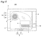
- a cooking device 100 known as a convection oven for cooking a cooking target with heat is typically constructed as shown in Fig 17.
- Fig 17 is a diagram showing an outline of the construction of such a conventional cooking device 100.
- the cooking device 100 is composed of a box-shaped member 2 that is thermally insulated; a heating chamber 3 that is formed inside the box-shaped member 2 to permit a cooking target to be placed therein; heating means 4 that heats the cooking target placed in the heating chamber 3, and blowing means 5.
- the blowing means 5 is provided with a blowing machine 54, which is composed of: a centrifugal fan 51; a drive motor 52 that drives the centrifugal fan 51; and a fan casing 53 that communicates with the heating chamber 3 through a suction port 6 and a blowoff port 7 and on which the centrifugal fan 51 is pivoted.
- the hot air heated by the heating means 4 is introduced into the heating chamber 3 by the blowing means 5 so that the air inside the heating chamber 3 is heated and circuited in such a way as to make the temperature inside the heating chamber 3 uniform and thereby cook the cooking target with heat.
- This cooking method has the disadvantage of requiring rather a long time for cooking
- the time required for cooking can be shortened by increasing the rotation rate of the centrifugal fan so as to increase the wind volume, and by increasing the amount of heat generated by the heater. This, however, results in not only greatly increased power consumption but also greatly increased noise, which constitutes a critical drawback.
- Japanese Patent Application Laid-Open No. H9-503334 discloses a cooking device that adopts, instead of the hot-wind-circulation method mentioned above, a cooking method whereby the air heated by heating means is blown directly at a cooking target so as to cook the cooking target with heat (hereinafter, this method will be referred to as the hot-air-impact method).
- the hot-wind-circulation method and the hot-air-impact method differ from each other in that, whereas the former operates blowing means for the purpose of making the temperature inside a heating chamber uniform and, by using the thus uniformized heat, applies heat uniformly to a cooking target, the latter blows hot air at a cooking target from a predetermined direction and, by using the hot air, cooks the cooking target with heat.
- cooking is achieved by making the hot air heated by a heater hit a cooking target at a high speed by the action of a blowing machine. This helps greatly reduce the time required for cooking without unduly increasing the power consumption by the heater.
- the hot-air-impact method is very suitable for the cooking of a chunk of meat such as chicken to be roasted, or pizza, or the like, i.e., a cooking target of which the cooking is not interfered with by the wind pressure of a hot air impact.
- the hot-air-impact method is unsuitable for the cooking of sponge cake or the like, i.e., a cooking target that is cooked by producing bubbles therein, or a cooking target that contains much air. The reason is that, inconveniently, the wind pressure of a hot air impact causes such a cooking target to become unacceptably deformed, unduly hard, or charred at the surface, and thereby interferes with the cooking thereof.
- An object of the present invention is to provide a cooking device that, alone, permits the use of a plurality of cooking methods so as to be capable of cooking any type of cooking target.
- a cooking device is provided with a box-shaped member, a heating chamber that is formed inside the box-shaped member to permit a cooking target to be placed therein, a first and a second heating device for heating the cooking target placed in the heating chamber, reversibly rotatable fan for introducing the hot air heated by the first and second heating devices into the heating chamber, a controller for controlling the first and second heating devices and the fan, a suction port formed in a wall surface of the heating chamber, a first and a second blowoff port formed respectively in different wall surfaces of the heating chamber, and a branch air-blow passage that branches air that has been sucked in via the suction port by rotation of the fan in a first blowoff port direction and a second blowoff port direction.
- cooking is performed by a plurality of cooking methods thanks to the fan adjusting passages Accordingly, by appropriately devising a control method by which to cook a particular cooking target, it is possible to realize, on a single cooking device, both a cooking method that is suitable for the cooking of a chunk of meat such as chicken to be roasted, or pizza, or the like, i.e., a cooking target of which the cooking is not interfered with by the wind pressure of a hot air impact and a cooking method that is suitable for the cooking of sponge cake or the like, i.e., a cooking target that is cooked by producing bubbles therein, or a cooking target that contains much air.
- a cooking method that is suitable for the cooking of a chunk of meat such as chicken to be roasted, or pizza, or the like i.e., a cooking target of which the cooking is not interfered with by the wind pressure of a hot air impact
- a cooking method that is suitable for the cooking of sponge cake or the like i.e., a cooking target that is cooked
- the heating means includes a first heating device and a second heating device
- the blowing means includes a first blowing machine that communicates with the heating chamber via a first suction port and a first blowoff port and that introduces hot air heated by the first heating device into the heating chamber and a second blowing machine that communicates with the heating chamber via a second suction port and a second blowoff port and that introduces hot air heated by the second heating device into the heating chamber
- the controlling means controls the first heating device, the first blowing machine, the second heating device, and the second blowing machine.
- the heating device uses a first cooking method and a second cooking method
- the first cooking method is one whereby hot air is blown out via the first blowoff port at a speed of 65 km/h or more and hot air is blown out via the second blowoff port at a speed of 30 km/h or less
- the second cooking method is one whereby hot air is blown out via the second blowoff port into the heating chamber are adjusted individually in one of the following manners.
- the branch air-blow passage is built with a two-way branch duct that branches in the first blowoff port direction and the second blowoff port direction, and at the branch point of the two-way branch duct is provided wind volume adjusting means for adjusting the wind volumes branched in two directions.
- the branch air-blow passage is built with a two-way branch fan casing that branches in the first blowoff port direction and the second blowoff port direction, and the wind volumes branched in two directions are adjusted by the controller controlling the fan rotation rate and/or the fan rotation direction of the fan.
- the first blowoff port is formed in the surface that faces the surface on which the cooking target is placed
- the second blowoff port is formed in another surface
- the air-blow passage that connects the suction port to the first blowoff port and the air-blow passage that connects the suction port to the second blowoff port branch from the fan in two directions so as to each describe an L-like or otherwise angled shape.
- the fan driving means adjusting the rotation rate and switching the rotation direction, it is possible to change not only the wind volumes blown out via the two blowoff ports but also the ratio of the wind speeds at the two blowoff ports. Specifically, when the fan is rotating in one direction, the wind volume and/or the wind speed at one blowoff port is higher than the wind volume and/or the wind speed at the other blowoff port; when the fan is rotating in the opposite direction, the wind volume and/or the wind speed at the former blowoff port is lower than the wind volume and/or the wind speed at the latter blowoff port. device that realizes different cooking methods than when a plurality of blowing machines are used.
- the blowing means includes a duct through which the air blown off from the blowing machine is guided to the blowoff ports, and the branch air-blow passage is arranged in the duct and is built as a two-way branch duct that permits the air blown off from the blowing machine to be branched in two directions.
- the branch air-blow passage is arranged in a duct. This makes it possible to branch air in two directions easily with a simple construction.
- the blowing machine includes a fan casing, the branch air-blow passage is formed by the fan casing, and the blowing machine is a two-way blowing machine that can blow off air in two directions.
- the branch air-blow passage is formed by a fan casing. This makes it possible to branch air in two directions easily with a simple construction.
- the branch air-blow passage includes wind volume adjusting means for adjusting the wind volumes branched in the two directions, and the controlling means adjusts the wind volumes by controlling the wind volume adjusting means.
- the wind volumes branched in two directions can be adjusted freely. This makes it possible to set the wind volumes freely at such levels as are suitable for different cooking methods.
- the wind volume adjusting means is a damper device.
- the wind volume adjusting means is built as a damper device having an appropriate shape. This helps reduce the cost of a cooking device that permits the wind volumes to be set freely at such levels as are suitable for different cooking methods.
- the wind volume adjusting means is a throttling device. cooking methods suitable respectively for different types of cooking target having utterly different properties from one another as described above.
- the air-blow passage that connects the suction port to the first blowoff port becomes increasingly large along the air-blow direction.
- this air-blow passage functions as a so-called diffuser by converting the kinetic energy of the wind flowing therethrough into a static pressure. This augments the wind that is guided to the air-blow passage that connects the suction port to the first blowoff port.
- the former state helps augment the impact of the hot air that is blown at the cooking target at a high speed from the direction in which is located the surface that faces the surface on which the cooking target is placed
- the latter state helps diminish the speed of the wind that is blown at the cooking target from the direction in which is located the surface that faces the surface on which the cooking target is placed.
- the air-blow passage that connects the suction port to the first blowoff port has a larger cross-sectional area than the other air-blow passage.
- the air volume and/or the wind speed of the air blown out via the first blowoff port is much higher than the air volume and/or the wind speed of the air blown out via the second blowoff port; when the fan is rotating in the opposite direction, the air volume and/or the wind speed of the air blown out via the first blowoff port is slightly lower than the air volume and/or the wind speed of the air blown out via the second blowoff port.
- the first cooking method it is possible to perform cooking by a hot-air-impact method
- the second cooking method it is possible to perform cooking by a double-stage hot-wind-circulation method.
- the heating chamber includes rotating means for rotating the cooking target in the heating chamber, and the rotating means is operated when the cooking target is cooked.
- the heating means includes an induction heating device, and the induction heating device is operated when the cooking target is cooked.
- the suction port and the blowoff port are formed in different wall surfaces of the heating chamber.
- the suction port and the blowoff port are formed in different wall surfaces of the heating chamber. This helps minimize unevenness in the temperature inside the heating chamber
- the plurality of blowoff ports are formed in different wall surfaces of the heating chamber.
- the plurality of blowoff ports are formed in different wall surfaces of the heating chamber. This makes it possible to control the wind speeds at the blowoff ports individually and, through selection from or combination thereof, to easily realize, on a single cooking device, a plurality of cooking methods having utterly different effects from one another.
- a cooking device is provided with a heating chamber in which a cooking target is placed, a suction port and two blowoff ports formed so as to penetrate wall surfaces of the heating chamber, air-blow passages that connect the suction port to one of or the other of the two blowoff ports, and blowing means for blowing the wind sucked in via the suction port into the heating chamber via the blowoff ports through the plurality of air-blow passages.
- the blowing means includes a fan and fan driving means for driving the fan in the forward or reverse direction, one of the two blowoff ports is formed in the surface that faces the surface on which the cooking target is placed, the other of the two blowoff ports is formed in another surface, and the air-blow passage that connects the suction port to one of the two blowoff ports and the air-blow passage that connects the suction port to the other of the two blowoff ports branch from the fan in two directions so as to each describe an L-like or otherwise angled shape.
- the fan driving means adjusting the rotation rate and switching the rotation direction, it is possible to change not only the wind volumes blown out via the two blowoff ports but also the ratio of the wind speeds at the two blowoff ports. Specifically, when the fan is rotating in one direction, the wind volume and/or the wind speed at one blowoff port is higher than the wind volume and/or the wind speed at the other blowoff port; when the fan is rotating in the opposite direction, the wind volume and/or the wind speed at the former blowoff port is lower than the wind volume and/or the wind speed at the latter blowoff port.
- a cooking device that permits air to be blown in the manner described above can be realized without the use of a special device.
- one of the branched air-blow passages is formed so as to run from the fan in the direction in which is located the surface that faces the surface on which the cooking target is placed.
- the wind volume and/or the wind speed at the blowoff port formed in the surface that faces the surface on which the heating target is placed is higher than the wind volume and/or the wind speed at the other blowoff port; when the fan is rotating in the opposite direction, the wind volume and/or the wind speed at the blowoff port formed in the ceiling surface of the heating chamber is lower than the wind volume and/or the wind speed at the other blowoff port
- the former blowing method it is possible to perform cooking chiefly by the hot-air-impact method.
- the latter blowing method it is possible to perform cooking by a cooking method suitable for sponge cake or the like, i.e, a cooking target that is cooked by producing bubbles therein, or a cooking target that contains much air from the beginning, that is, collectively, a cooking target of which the cooking is interfered with by a hot air impact.
- a single cooking device different cooking methods suitable respectively for different types of cooking target having utterly different properties from one another as described above.
- the air-blow passage that is formed so as to run from the fan in the direction in which is located the surface that faces the surface on which the cooking target is placed becomes increasingly large along the air-blow direction.
- the air-blow passage that is formed so as to run from the fan in the direction in which is located the surface that faces the surface on which the cooking target is placed is higher than the wind volume and/or the wind speed of the air that flows through the other air-blow passage
- the air-blow passage that is formed so as to run from the fan in the direction in which is located the surface that faces the surface on which the cooking target is placed becomes increasingly large along the air-blow direction
- the air-blow passage that is formed so as to run from the fan in the direction in which is located the surface that faces the surface on which the cooking target is placed functions as a so-called diffuser by converting the kinetic energy of the wind flowing therethrough into a static pressure.
- the air-blow passage that is formed so as to run from the fan in the direction in which is located the surface that faces the surface on which the cooking target is placed has a larger cross-sectional area than the other air-blow passage.
- the air volume and/or the wind speed of the air blown out via the blowoff port formed in the surface that faces the surface on which the cooking target is placed is much higher than the air volume and/or the wind speed of the air blown out via the other blowoff port; when the fan is rotating in the opposite direction, the air volume and/or the wind speed of the air blown out via the blowoff port formed in the surface that faces the surface on which the cooking target is placed is slightly lower than the air volume and/or the wind speed of the air blown out via the other blowoff port.
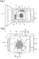
- Fig. 1 is a partially see-through perspective view showing the construction of the cooking device 1 of the first embodiment, with the thermally insulated door 21 opened
- Fig. 2 is a sectional view of the same cooking device 1.
- the cooking device 1 is composed of: a box-shaped member 2 that is thermally insulated and that has an opening formed in the front surface thereof; a heating chamber 3 that is formed inside the box-shaped member 2 to permit a cooking target to be placed therein; heating means 4 that heats the cooking target, blowing means 5 that sends the hot air heated by the heating means 4 into the heating chamber 3; controlling means 8 that controls the heating means and/or the blowing means 5; and rotating means 9 that rotates the cooking target.
- a thermally insulated door 21 that openably closes the opening formed in that surface, and an operation panel 81 that accepts instructions from the user.
- a turntable 95 On the floor surface of the heating chamber 3, there is provided, as the rotating means 9 for rotating the cooking target, a turntable 95.
- the turntable 95 is rotated by a drive motor 91, permits a rotary dish, meshed rack, or double-stage rack to be placed interchangeably thereon, and can rotate along therewith.
- the blowing means 5 is built with a blowing machine 54, which is composed of: a centrifugal fan 51; a reversible motor 52b that drives the centrifugal fan 51 and that can rotate in the forward and reverse directions; a two-way branch fan casing 53c on which the centrifugal fan 51 is pivoted and that branches in the direction of a ceiling-surface blowoff port 71 and in the direction of a side-surface blowoff port 72.
- the hot air heated by a first heater 411 provided as the heating means 4 is introduced into the heating chamber 3 via the ceiling-surface blowoff port 71, and the hot air heated by a second heater 412 is introduced into the heating chamber 3 via the side-surface blowoff port 72.
- the reversible motor 52b rotates at a high rate in the direction indicated as "A" in Fig. 2, and rotates at a low rate in the direction indicated as "B" in Fig. 2.
- a suction port 6 and the side-surface blowoff port 72 each consist of a plurality of punched holes each 5 mm across.
- the ceiling-surface blowoff port 71 consists of a plurality of nozzles each 11 mm across.
- an induction heating device 42 for assisting cooking.
- a controller 82 provided as the controlling means 8 selects a suitable cooking method from a plurality of preprogrammed cooking methods, and controls the operation of the reversible motor 52b of the blowing machine 54, the first and second heaters 411 and 412, the induction heating device 42, and the turntable drive motor 91 to perform the cooking of the cooking target.
- a meshed rack (not illustrated) is placed on the turntable 95 inside the heating chamber 3, then a chunk of chicken is put on the meshed rack, and then, from the menu items displayed on the operation panel 81, the one for roasted chicken is selected.
- the controller 82 operates the reversible motor 52b of the blowing machine 54, the first and second heaters 411 and 412, the induction heating device 42, and the turntable drive motor 91. Specifically, in this case, the centrifugal fan 51 is rotated by the reversible motor 52b at a high rate in the direction indicated by arrow A in Fig.
- the induction heating device 42 may be energized to assist cooking.
- the controller 82 operates the reversible motor 52b of the blowing machine 54, the second heater 412, the induction heating device 42, and the turntable drive motor 91, and, as necessary, operates the first heater 411. Specifically, in this case, the centrifugal fan 51 is rotated by the reversible motor 52b at a low rate in the direction indicated by arrow B in Fig.
- This control permits a double-stage hot-wind-circulation cooking method, and thus permits preparation of fluffy sponge cake on each stage of the double-stage rack.
- the two blowoff ports may be arranged in a different manner than illustrated in the figure; for example, they may be arranged in the ceiling and rear surfaces, in the ceiling and front surfaces, in the floor and side surfaces, in the floor and rear surfaces, or in the floor and front surfaces. It is possible even to arrange at least one of two or more blowoff ports in a wall surface different from the wall surface in which the other blowoff ports are formed. With any of these arrangements, it is possible to obtain almost the same effects. Accordingly, although the two blowoff ports are arranged in the ceiling and side surfaces in the cooking device 1 of this embodiment, this is not meant to limit in any way how many blowoff ports should be formed and where they should be arranged.
- the rotation rate of the reversible motor 52b of the blowing machine 54 is variable, and therefore cooking can be performed at a wind speed other than those specifically given above.
- the first and second heaters 411 and 412 and the induction heating device 42 can be turned on and off, and the amounts of heat generated by them can be adjusted. This make it possible to realize different cooking methods suitable for the cooking of various cooking targets
- the blowing machine 54 may use, as the centrifugal fan 51, a sirocco fan, radial fan, or turbo fan, or, to make the best of a limited space or out of other consideration, an axial-flow fan, inclined-flow fan, or through-flow fan.
- the blowing machine 54 may be replaced with a blower.
- the shape of the fan casing 53 may be rectangular, spiral, or arc-shaped, so long as it can branch an air flow in two directions.
- the punched holes of the suction port 6 and the side-surface blowoff port 72 may be given any other diameter than 5 mm to obtain the same effects. Those holes do not have to be formed as punched holes, but may be formed as slits or a net. The same is true with the ceiling-surface blowoff port 71; that is, the holes there may be given any other diameter than 11 mm to obtain the same effects.
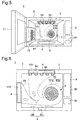
- Fig. 3 is a partially see-through perspective view showing the construction of the cooking device 1 of the second embodiment, with the thermally insulated door 21 opened
- Fig. 4 is a sectional view of the same cooking device 1.
- the cooking device 1 of this embodiment differs from the cooking device 1 of the first embodiment shown in Figs. 1 and 2 in the following respects
- a damper device 83 Inside the two-way branch fan casing 53c, there is provided a damper device 83.
- the damper device 83 permits adjustment of the wind volumes sent from the blowing machine 54 in the direction of the ceiling-surface blowoff port 71 and in the direction of the side-surface blowoff port 72 Moreover, at the ceiling-surface blowoff port 71, there is provided a throttling device 84.
- the throttling device 84 permits adjustment of the wind speed blown out via the ceiling-surface blowoff port 71.
- the cooking device 1 of this embodiment is constructed in the same manner as the cooking device 1 of the first embodiment, and therefore such components as are common to the two embodiments are identified with the same reference numerals, and their explanations will not be repeated
- the cooking device 1 of this embodiments offers the same effects as the cooking device 1 of the first embodiment.
- the damper device 83 provided inside the fan casing 53c and the throttling device 84 provided at the ceiling-surface blowoff port 71 it is possible to easily adjust the wind speeds blown out via the ceiling-surface and side-surface blowoff ports 71 and 72, and to more finely control the wind speeds.
- the wind speeds can be finely adjusted during cooking, it is no longer necessary to strictly determine, at the design stage, the wind volumes branched into the two directions of the two-way branch fan casing 53c. This helps greatly simplify the design of the two-way branch fan casing 53c, and thus helps reduce the production cost.
- Fig. 5 is a partially see-through perspective view showing the construction of the cooking device 1 of the third embodiment, with the thermally insulated door 21 opened
- Fig. 6 is a sectional view of the same cooking device 1.
- the cooking device 1 of this embodiment differs from the cooking device 1 of the first embodiment shown in Figs. 1 and 2 in the following respects.
- the blowing machine 54 is composed of: a sirocco fan 51a; a drive motor (not illustrated) that drives the sirocco fan 51a and that rotates only in one direction; and a spiral fan casing 53b that blows off air only in one direction.
- the outlet of the spiral fan casing 53b communicates with a two-way branch duct 55, and thus the air sent from the blowing machine 54 is branched by the two-way branch duct 55 in the direction of the ceiling-surface blowoff port 71 and in the direction of the side-surface blowoff port 72.
- a rotary damper device 83 At the branch point of the two-way branch duct 55, there is provided a rotary damper device 83, and this damper device 83 permits adjustment of the wind volumes sent from the blowing machine 54 in the direction of the ceiling-surface blowoff port 71 and in the direction of the side-surface blowoff port 72 Moreover, at the ceiling-surface blowoff port 71, there is provided a throttling device 84, and this throttling device 84 permits adjustment of the wind speed blown out via the ceiling-surface blowoff port 71.
- the cooking device 1 of this embodiment is constructed in the same manner as the cooking device I of the first embodiment, and therefore such components as are common to the two embodiments are identified with the same reference numerals, and their explanations will not be repeated.
- the cooking device 1 of this embodiments offers the same effects as the cooking device 1 of the first embodiment.
- the blowing machine 54 is built with a sirocco fan 51a and a spiral fan casing 53b. This helps enhance the blowing efficiency of the blowing machine 54 and reduce the noise it produces.
- the fan drive motor is a motor that rotates only in one direction. This helps increase efficiency and reduce cost.
- the damper device 83 provided in the two-way branch duct 55 and the throttling device 84 provided at the ceiling-surface blowoff port 71 it is possible not only to easily adjust the wind speeds blown out via the ceiling-surface and side-surface blowoff ports 71 and 72 but also to more finely adjust the wind speeds.
- Fig. 7 is a partially see-through perspective view showing the construction of the cooking device 1 of the fourth embodiment, with the thermally insulated door 21 opened
- Fig. 8 is a sectional view of the same cooking device 1.
- the cooking device 1 of this embodiment differs from the cooking device 1 of the first embodiment shown in Figs. 1 and 2 in the following respects.
- the blowing means 5 is built with two blowing machines, namely a first blowing machine 541 and a second blowing machine 542.
- the first blowing machine 541 is composed of: a sirocco fan 51a; a drive motor (not illustrated) that drives the sirocco fan 51a and that rotates only in one direction; and a spiral fan casing 53b that commutates with the heating chamber 3 via a first blowoff port 61 and via the ceiling-surface blowoff port 71 and that blows off air only in one direction.
- the second blowing machine 542 is composed of: a sirocco fan 51b; a drive motor (not illustrated) that drives the sirocco fan 51b and that rotates only in one direction; and a spiral fan casing 53c that communicates with the heating chamber 3 via a second blowoff port 62 and via the side-surface blowoff port 72 and that blows off air only in one direction.
- the cooking device 1 of this embodiment is constructed in the same manner as the cooking device 1 of the first embodiment, and therefore such components as are common to the two embodiments are identified with the same reference numerals, and their explanations will not be repeated.
- the cooking device 1 of this embodiments offers the same effects as the cooking device 1 of the first 'embodiment.
- the first and second blowing machines 541 and 542 are built with sirocco fans 51a and 51b and spiral fan casings 53b and 53c, respectively. This helps increase blow efficiency and reduce noise.
- the fan drive motor is a motor that rotates only in one direction. This helps increase efficiency and reduce cost.
- the wind speeds blown out via the ceiling-surface and side-surface blowoff ports 71 and 72 can be adjusted simply by controlling the rotation rates of the first and second blowing machines 541 and 542. This makes it possible to very easily adjust the wind speeds blown out via the ceiling-surface and side-surface blowoff ports 71 and 72.
- Fig. 9 is a side sectional view showing the construction of the cooking device 1 of the fifth embodiment
- Fig. 10 is a side sectional view illustrating the operation of the same cooking device 1.
- the cooking device 1 of this embodiment differs from the cooking device 1 of the first embodiment shown in Figs. 1 and 2 in the following respects.
- the blowing means 5 is built with a blowing machine 54, which is composed of a sirocco fan 51a; a drive motor (not illustrated) that drives the sirocco fan 51a and that rotates only in one direction; and a spiral fan casing 53b that communicates with the heating chamber 3 via a blowoff port 6 and via a first ceiling-surface blowoff port 711 or a second ceiling-surface blowoff port 712 and that blows off air only in one direction, and a damper device 83 that switches between the first and second ceiling-surface blowoff ports 711 and 722 as the blowoffport via which the air sent from the sirocco fan 51a is blown into the heating chamber 3.
- a blowing machine 54 which is composed of a sirocco fan 51a; a drive motor (not illustrated) that drives the sirocco fan 51a and that rotates only in one direction; and a spiral fan casing 53b that communicates with the heating chamber 3 via a blowoff port 6 and via a first ceiling-surface blowoff port 711 or a second
- the cooking device 1 of this embodiment is constructed in the same manner as the cooking device 1 of the first embodiment, and therefore such components as are common to the two embodiments are identified with the same reference numerals, and their explanations will not be repeated.
- the controller 82 (see Fig. 2) provided as the controlling means 8 (see Fig. 1) selects a suitable cooking method from a plurality of preprogrammed cooking methods, and controls the operation of the drive motor 52 of the blowing machine 54, the heater 41, the induction heating device 42 (see Fig. 2), and the turntable drive motor 91 to perform the cooking of the cooking target
- a meshed rack (not illustrated) is placed on the turntable 95 inside the heating chamber 3, then a chunk of chicken is put on the meshed rack, and then, from the menu items displayed on the operation panel 81 (see Fig. 1), the one for roasted chicken in selected.
- the controller 82 instructs the damper device 83 to switch the blowoff port of the blowing machine 54 to the first ceiling-surface blowoff port 711 as shown in Fig. 9, and operates the drive motor 52 of the blowing machine 54, the heater 41, the induction heating device 42 (see Fig. 2), and the turntable drive motor 91.
- the sirocco fan 51a is rotated by the drive motor 52 at a high rate, so that hot air is blown out via the first ceiling-surface blowoff port 711 at a speed of 50 km/h or more
- This control permits a hot-air-impact cooking method, and thus permits quick preparation of roasted chicken.
- a double-stage rack (not illustrated) is placed on the turntable 95 inside the heating chamber 3, then a lump of dough is put on each stage of the double-stage rack, and then, from the menu items displayed on the operation panel 81 (see Fig. 1), the one for sponge cake is selected.
- the controller 82 instructs the damper device 83 to switch the blowoff port of the blowing machine 54 to the second ceiling-surface blowoff port 712 as shown in Fig. 10, and operates the drive motor 52 of the blowing machine 54, the heater 41, the induction heating device 42 (see Fig 2), and the turntable drive motor 91.
- the sirocco fan 51a is rotated by the drive motor 52 at a low rate, so that hot air is blown out via the second ceiling-surface blowoff port 712 at a speed of 50 km/h or less.
- This control permits a double-stage hot-wind-circulation cooking method, and thus permits preparation of fluffy sponge cake on each stage of the double-stage rack.
- the rotation rate of the drive motor 52 of the blowing machine 54 is variable, and therefore cooking can be performed at a wind speed other than those specifically given above.
- the heater 41 and the induction heating device 42 can be turned on and off, and the amounts of heat generated by them can be adjusted This make it possible to realize different cooking methods suitable for the cooking of various cooking targets.
- the cooking device 1 of this embodiments offers the same effects as the cooking device 1 of the first embodiment.
- the blowing machine 54 is built with a sirocco fan 51a and a spiral fan casing 53b. This helps increase blow efficiency and reduce noise.
- the fan drive motor 52 is a motor that rotates only in one direction. This helps increase efficiency and reduce cost.
- the wind speeds blown out via the first and second ceiling-surface blowoff ports 711 and 712 can be adjusted simply by controlling the rotation rate of the blowing machine 54. This makes it possible to very easily adjust the wind speeds blown out via the first and second ceiling-surface blowoff ports 711 and 712.
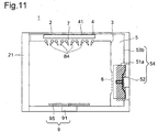
- Fig. 11 is a side sectional view showing the construction of the cooking device 1 of the sixth embodiment.
- the cooking device 1 of this embodiment differs from the cooking device 1 of the fifth embodiment shown in Figs. 9 and 10 in the following respects.
- the cooking device 1 of this embodiment is constructed in the same manner as the cooking device 1 of the fifth embodiment, and therefore such components as are common to the two embodiments are identified with the same reference numerals, and their explanations will not be repeated.
- the controller 82 (see Fig. 2) provided as the controlling means 8 (see Fig. 1) selects a suitable cooking method from a plurality of preprogrammed cooking methods, and controls the operation of the drive motor 52 of the blowing machine 54, the heater 41, the induction heating device 42 (see Fig. 2), and the turntable drive motor 91 to perform the cooking of the cooking target.
- a meshed rack (not illustrated) is placed on the turntable 95 inside the heating chamber 3, then a chunk of chicken is put on the meshed rack, and then, from the menu items displayed on the operation panel 81 (see Fig. 1), the one for roasted chicken in selected.
- the controller 82 (see Fig. 2) operates the throttling device 84 in such a way as to reduce the area of the blowoff port 7, and operates the drive motor 52 of the blowing machine 54, the heater 41, the induction heating device 42 (see Fig. 2), and the turntable drive motor 91.
- the sirocco fan 51a is rotated by the drive motor 52 at a high rate, so that hot air is blown out via blowoff port 7 at a speed of 50 km/h or more.
- This control permits a hot-air-impact cooking method, and thus permits quick preparation of roasted chicken.
- a double-stage rack (not illustrated) is placed on the turntable 95 inside the heating chamber 3, then a lump of dough is put on each stage of the double-stage rack, and then, from the menu items displayed on the operation panel 81 (see Fig 1), the one for sponge cake is selected.
- the controller 82 (see Fig. 2) operates the throttling device 84 in such a way as to increase the area of the blowoff port 7, and operates the drive motor 52 of the blowing machine 54, the heater 41, the induction heating device 42 (see Fig. 2), and the turntable drive motor 91.
- the sirocco fan 51a is rotated by the drive motor 52 at a low rate, so that hot air is blown out via the blowoff port 7 at a speed of 50 km/h or less.
- This control permits a double-stage hot-wind-circulation cooking method, and thus permits preparation of fluffy sponge cake on each stage of the double-stage rack.
- the rotation rate of the drive motor 52 of the blowing machine 54 is variable, and therefore cooking can be performed at a wind speed other than those specifically given above
- the heater 41 and the induction heating device 42 can be turned on and off, and the amounts of heat generated by them can be adjusted. This make it possible to realize different cooking methods suitable for the cooking of various cooking targets.
- the cooking device 1 of this embodiments offers the same effects as the cooking device 1 of the fifth embodiment.
- the construction is further simplified. This helps reduce the number of components, and helps further reduce cost.
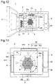
- Fig. 12 is a perspective view showing an outline of the construction of the cooking device 1 of the seventh embodiment as seen from the surface (front surface) in which the opening of the heating chamber is formed, with the thermally insulated door opened 21. This figure is partially made see-through to show the air-blow passages, for easy understanding of how air flows.
- the cooking device 1 is composed of: a box-shaped member 2 that has the shape of a rectangular parallelepiped, a heating chamber 3 that is formed inside the box-shaped member 2, that is thermally insulated from the box-shaped member 2 by an insulating material (not illustrated), and that permits a cooking target to be placed therein; heating means 4 (see Fig. 13) that heats the cooking target; blowing means 5 that sends the hot air heated by the heating means into the heating chamber 3; controlling means 8 (see Fig. 13) that controls the heating means 4 and the blowing means 5; and rotating means 9 that permits the cooking target to be placed thereon directly or via a rack placed thereon and that permits the cooking target to be rotated.
- the front surface of the heating chamber 3 refers to the surface thereof in which the opening of the heating chamber 3 is formed
- the front surface of the heating chamber 3 refers to the surface thereof in which the opening of the heating chamber 3 is formed
- the rear surface of the heating chamber 3 refers to the surface thereof that is opposite to the front surface thereof
- the direction from the rear surface to the front surface is referred to as the frontward direction
- the direction from the front surface to the rear surface is referred to as the rearward direction.
- the floor surface of the heating chamber 3 refers to the surface thereof on which the cooking target is placed
- the ceiling surface of the heating chamber 3 refers to the surface thereof that faces that floor surface thereof.
- the direction from the floor surface to the ceiling surface is referred to as the upward direction
- the direction from the ceiling surface to the floor surface is referred to as the downward direction.
- FIG. 13 is an outline sectional view showing an up-down-direction section of the cooking device 1 of this embodiment taken substantially at the center thereof in the front-rear direction.
- the blowing means 5 In the cooking device 1, behind the rear surface 3 of the heating chamber 3 but in front of the rear surface of the box-shaped member 2 is provided the blowing means 5 In a part of the rear surface of the heating chamber 3 facing the blowing means 5, there is formed an opening (hereinafter referred to as the suction port 6) consisting of a plurality of punched holes via which air is sucked in when the blowing means 5 is operated.
- the blowing means 5 is provided with a centrifugal fan 51 and a reversible motor 52b that can rotate in the forward and backward directions.
- the centrifugal fan 51 is pivoted on the reversible motor 52b.
- a two-way branch fan casing 53c that branches in two directions, namely into an upper air-blow passage 56a through which the wind sent from the blowing means 5 is guided upward and a side air-blow passage 56b through which the wind is guided sideways (in Fig. 12, leftward as seen from the viewer facing it).
- the shape of the two-way branch fan casing 53c may vary; specifically, it may have, at the branch point 57 thereof at which the upper and side air-blow passages 56a and 56b branch off, an angle of, for example, substantially 90 degrees as shown in Fig. 12, or an acute angle (see Fig. 14), or, though not illustrated, an obtuse angle.
- the shape of the air-blow passage is referred to as "L-shaped" when it has an angle of 90 degrees at the branch point as described above and collectively as "angled” when it has an acute or obtuse angle.
- a ceiling-surface blowoff port 71 that communicates with the upper air-blow passage 56a and that consists of a plurality of through holes each, for example, 11 mm across.
- a side-surface blowoff port 72 that communicates with the side air-blow passage 56b and that consists of a plurality of punched holes.
- an operation panel 81 that accepts instructions for cooking from the user. Moreover, behind the operation panel 81, in the space between the surface of the heating chamber 3 opposite to the surface thereof in which the side-surface blowoff port 27 is formed and the side surface of the box-shaped member 2, there is provided controlling means 8.
- the wind sucked in via the suction port 6 is branched by the two-way branch fan casing 53c into a part that is sent to the upper air-blow passage 56a and a part that is sent to the side air-blow passage 56b.
- the wind that passes through the upper air-blow passage 56a absorbs heat from and is thereby heated by an upper heater 411 that is heated by being energized, and is then blown out at a speed of 65 km/h or more via the ceiling-surface blowoff port 71 at the cooking target.
- the wind that passes through the side air-blow passage 56b absorbs heat from and is thereby heated by a side heater 412 that is heated by being energized, and is then blown out at a speed of 30 km/h or less via the side-surface blowoff port 72 at the cooking target.
- This control permits a hot-air-impact cooking method, and thus permits quick preparation of roasted chicken.
- the induction heating device 42 may be energized to assist cooking.
- a placement rack (not illustrated) is placed in an upper and a lower part inside the heating chamber 3, then a lump of dough is put on each rack of the placement rack, and then, from the menu items displayed on the operation panel 81, the one for sponge cake is selected.
- the controller 82 operates the drive motor 52 of the blowing machine 54, the side heater 412, the induction heating device 42, and the turntable drive motor 91, and, as necessary, operates the upper heater 411.
- the centrifugal fan 51 is rotated by the reversible motor 52b in the direction indicated by arrow B in Fig. 2 at a lower rate than when rotated in the direction indicated by arrow A as described above.
- the above-described two cooking methods having utterly different effects are realized by individually controlling and appropriately selecting from or combining together the wind speeds at the plurality of blowoff ports formed in different wall surfaces of the heating chamber.
- the two blowoff ports may be arranged in a different manner than in the cooking device 1 of this embodiment; for example, they may be arranged in the ceiling and rear surfaces, in the ceiling and front surfaces, in the floor and side surfaces, in the floor and rear surfaces, or in the floor and front surfaces. It is possible even to arrange at least one of two or more blowoff ports in a wall surface different from the wall surface in which the other blowoff ports are formed. With any of these arrangements, it is possible to obtain almost the same effects. Accordingly, although the two blowoff ports are arranged in the ceiling and side surfaces in the cooking device 1 of this embodiment, this is not meant to limit in any way how many blowoff ports should be formed and where they should be arranged.
- the side-surface blowoff port 72 and the controlling means 8 and/or the operation panel 81 be arranged so as to face each other as described above. This prevents the controlling means 8 and/or operation panel 81 from being influenced by the hot wind passing through the side air-blow passage 56b, and thus eliminates the need to use highly heat-resistant components in the controlling means 8 and/or the operation panel 81.
- the rotation rate of the reversible motor 52b of the blowing machine 54 may be made variable. This makes it possible to perform cooking at a wind speed other than those specifically given above.
- the upper and side heaters 411 and 412 and the induction heating device 42 may be so designed that they can be turned on and off and the amounts of heat generated by them can be adjusted. This make it possible to realize different cooking methods suitable for the cooking of various cooking targets.
- the blowing machine 54 may use, as the centrifugal fan 51, a sirocco fan, radial fan, or turbo fan, or, to make the best of a limited space or out of other consideration, an axial-flow fan, oblique-flow fan, or through-flow fan.
- the blowing machine 54 may be replaced with a blower.
- the shape of the part of the two-way branch fan casing 53 diagonal to the branch point 57 may be rectangular as shown in Fig 13, spiral, or arc-shaped (see Fig. 14).
- the punched holes of the suction port 6 and the side-surface blowoff port 72 may be given any other diameter than 5 mm to obtain the same effects. Those holes do not have to be formed as punched holes, but may be formed as slits or a net. The same is true with the ceiling-surface blowoff port 71; that is, the holes there may be given any other diameter than 11 mm to obtain the same effects.
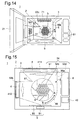
- Fig. 14 is a perspective view showing an outline of the construction of the cooking device 1 of the eighth embodiment as seen from the surface (front surface) in which the opening of the heating chamber 3 is formed, with the thermally insulated door opened 21. This figure is partially made see-through to show the air-blow passages, for easy understanding of how air flows.
- Fig. 15 is an outline sectional view showing an up-down-direction section of the cooking device 1 of this embodiment taken substantially at the center thereof in the front-rear direction.
- the cooking device 1 of this embodiment differs from the cooking device 1 of the seventh embodiment shown in Figs. 12 and 13 in the following respects.
- the cross-sectional area of the upper air-blow passage 56a near the centrifugal fan 51 is larger than the cross-sectional area of the side air-blow passage 56b near the 51.
- the upper air-blow passage 56a becomes increasingly large along the air-blow direction.
- the cooking device 1 of this embodiment is constructed in the same manner as the cooking device 1 of the seventh embodiment, and therefore such components as are common to the two embodiments are identified with the same reference numerals, and their explanations will not be repeated.
- the cooking device I of this embodiments offers, in addition to the effects offered by the cooking device I of the seventh embodiment, the following effects.
- the centrifugal fan 51 When the centrifugal fan 51 is rotated by the reversible motor 52B at a high rate in the direction indicated by arrow A shown in Fig. 15, the wind volume that passes through the air-blow passage 56a becomes far higher than the wind volume that passes through the air-blow passage 56b. Moreover, since the air-blow passage 56a becomes increasingly large along the air-blow direction, it functions as a so-called diffuser by converting the kinetic energy of the flowing wind into a static pressure. This greatly augments the wind guided upward from the heater 41 as compared with the same wind in the cooking device 1 of the seventh embodiment.
- Fig. 16 shows such a modified example.
- Fig. 16 is an outline sectional view showing an up-down-direction section of the cooking device 1 of the eighth embodiment as seen from the front surface and taken substantially at the center thereof in the front-rear direction, and is partially made see-through to show the air-blow passages.
- the two-way branch fan casing 53c may be shaped like the two-way branch fan casing 53d shown in Fig. 16. Specifically, the lower right-hand part 53d1 of the two-way branch fan casing 53d may be cornered, and the lower left-hand part 53d2 of the two-way branch fan casing 53d may bulge in a direction away from the centrifugal fan 51, or may cave in.
- the upper left-hand part 53d3 of the two-way branch fan casing 53d i.e., the part thereof (the so-called tongue-shaped part) at the edge of the branch point 57 at which the air-blow passage branches in two directions, may be round where it faces the centrifugal fan 51. This helps further reduce cooking noise.
- a cooking method suitable for the cooking of a chunk of meat such as chicken to be roasted, or pizza, or the like i.e., a cooking target of which the cooking is not interfered with by the wind pressure of a hot air impact and a cooking method suitable for the cooking of sponge cake or the like, i.e., a cooking target that is cooked by producing bubbles therein, or a cooking target that contains much air.
Landscapes
- Engineering & Computer Science (AREA)
- Chemical & Material Sciences (AREA)
- Combustion & Propulsion (AREA)
- Mechanical Engineering (AREA)
- General Engineering & Computer Science (AREA)
- Baking, Grill, Roasting (AREA)
Applications Claiming Priority (5)
| Application Number | Priority Date | Filing Date | Title |
|---|---|---|---|
| JP2001321291 | 2001-10-19 | ||
| JP2001321291 | 2001-10-19 | ||
| JP2002143969 | 2002-05-20 | ||
| JP2002143969 | 2002-05-20 | ||
| PCT/JP2002/010865 WO2003036174A1 (fr) | 2001-10-19 | 2002-10-18 | Appareil de cuisson |
Publications (3)
| Publication Number | Publication Date |
|---|---|
| EP1437552A1 true EP1437552A1 (de) | 2004-07-14 |
| EP1437552A4 EP1437552A4 (de) | 2005-11-16 |
| EP1437552B1 EP1437552B1 (de) | 2010-02-03 |
Family
ID=26623979
Family Applications (1)
| Application Number | Title | Priority Date | Filing Date |
|---|---|---|---|
| EP02777892A Expired - Lifetime EP1437552B1 (de) | 2001-10-19 | 2002-10-18 | Kochvorrichtung |
Country Status (4)
| Country | Link |
|---|---|
| US (1) | US7296510B2 (de) |
| EP (1) | EP1437552B1 (de) |
| DE (1) | DE60235283D1 (de) |
| WO (1) | WO2003036174A1 (de) |
Cited By (10)
| Publication number | Priority date | Publication date | Assignee | Title |
|---|---|---|---|---|
| EP1467154A3 (de) * | 2003-04-10 | 2005-05-25 | Samsung Electronics Co., Ltd. | Gargerät |
| DE102004046437A1 (de) * | 2004-09-24 | 2006-04-06 | BSH Bosch und Siemens Hausgeräte GmbH | Vorrichtung mit einer Gargeräteluftführungseinheit |
| WO2006121701A1 (en) * | 2005-05-06 | 2006-11-16 | Viking Range Corporation | Multi-mode convection oven with flow control baffles |
| EP2126473A1 (de) * | 2007-01-17 | 2009-12-02 | LG Electronics Inc. | Ofen |
| US7766003B2 (en) * | 2007-10-09 | 2010-08-03 | Samsung Electronics Co., Ltd. | Cooking apparatus and method for controlling the same |
| EP2273885A1 (de) * | 2008-04-03 | 2011-01-19 | Electrolux Home Products, Inc. | Automatischer rührstab |
| EP1542511B2 (de) † | 2003-12-10 | 2011-09-21 | Samsung Electronics Co., Ltd. | Verfahren zur Steuerung einer Kochvorrichtung |
| US8242413B2 (en) | 2006-11-29 | 2012-08-14 | Lg Electronics Inc. | Method of controlling oven |
| EP3460339A1 (de) * | 2017-09-22 | 2019-03-27 | Franke Technology and Trademark Ltd | Umluftherd mit zusätzlichem abdeckelement |
| CN114144619A (zh) * | 2019-07-31 | 2022-03-04 | 夏普株式会社 | 加热烹调器 |
Families Citing this family (11)
| Publication number | Priority date | Publication date | Assignee | Title |
|---|---|---|---|---|
| DE102006020914A1 (de) * | 2006-05-05 | 2007-11-08 | Electrolux Home Products Corp. N.V. | Garofen, insbesondere Haushaltsgarofen |
| EP1918647A1 (de) * | 2006-11-02 | 2008-05-07 | Electrolux Home Products Corporation N.V. | Ofen, insbesondere Haushaltsofen, sowie Verfahren zum Betrieb eines solchen Ofens |
| DE102007023767B4 (de) * | 2007-05-22 | 2011-01-05 | Rational Ag | Gargerät mit dynamischer Luftführung |
| US9534794B2 (en) | 2009-03-16 | 2017-01-03 | Whirlpool Corporation | Convection cooking appliance with circular air flow system |
| US8895902B2 (en) * | 2010-03-17 | 2014-11-25 | Duke Manufacturing Co. | Oven for heating food |
| DE102012217054A1 (de) * | 2012-09-21 | 2014-03-27 | E.G.O. Elektro-Gerätebau GmbH | Verfahren zum Betrieb eines Backofens und Backofen |
| US20140110391A1 (en) * | 2012-10-22 | 2014-04-24 | Miguel Estrella | Oven baffle |
| US20140110392A1 (en) * | 2012-10-22 | 2014-04-24 | Miguel Estrella | Oven baffle |
| US10119708B2 (en) * | 2013-04-23 | 2018-11-06 | Alto-Shaam, Inc. | Oven with automatic open/closed system mode control |
| CN105263379A (zh) * | 2013-06-04 | 2016-01-20 | 皇家飞利浦有限公司 | 基于空气的炸锅 |
| CN113180487B (zh) * | 2020-01-14 | 2022-09-16 | 宁波方太厨具有限公司 | 一种具有双向热风机的烤箱 |
Citations (5)
| Publication number | Priority date | Publication date | Assignee | Title |
|---|---|---|---|---|
| US4308853A (en) * | 1979-02-15 | 1982-01-05 | Rodger Thirode | Forced hot air alimentary oven |
| JPH06281148A (ja) * | 1993-03-30 | 1994-10-07 | Sharp Corp | 加熱調理器 |
| JPH09126464A (ja) * | 1995-11-01 | 1997-05-16 | Tokyo Gas Co Ltd | コンベクションオーブン |
| US6218650B1 (en) * | 1993-10-14 | 2001-04-17 | Fujimak Corporation | High speed oven using a jet of heated air |
| US20030000515A1 (en) * | 2001-06-27 | 2003-01-02 | Cole James T. | Convection oven having multiple airflow patterns |
Family Cites Families (29)
| Publication number | Priority date | Publication date | Assignee | Title |
|---|---|---|---|---|
| US4462383A (en) * | 1982-06-09 | 1984-07-31 | Lincoln Manufacturing Company, Inc. | Impingement food preparation apparatus |
| JPS6174018A (ja) | 1984-09-18 | 1986-04-16 | New Japan Radio Co Ltd | 定電流回路 |
| JPS6174018U (de) * | 1984-10-22 | 1986-05-19 | ||
| JP2503386B2 (ja) | 1985-03-18 | 1996-06-05 | 株式会社日本自動車部品総合研究所 | 車輪の異常検出装置 |
| JPH02503386A (ja) * | 1988-03-10 | 1990-10-18 | ピッツァ ハット インコーポレーテッド | ピザを焼く方法及びオーブン |
| JPH0623841Y2 (ja) | 1989-04-04 | 1994-06-22 | 三洋電機株式会社 | 調理器 |
| US6041398A (en) * | 1992-06-26 | 2000-03-21 | International Business Machines Corporation | Massively parallel multiple-folded clustered processor mesh array |
| JP2820770B2 (ja) | 1990-04-19 | 1998-11-05 | 株式会社ブリヂストン | 干渉型防音装置 |
| JPH041311U (de) * | 1990-04-20 | 1992-01-08 | ||
| US5434390A (en) | 1991-09-17 | 1995-07-18 | Turbochef, Inc. | Quick-cookig oven |
| IT1258527B (it) * | 1992-04-23 | 1996-02-27 | Vincenzo Cavallo | Apparecchiature per friggere prodotti alimentari a secco |
| US5649476A (en) * | 1994-08-22 | 1997-07-22 | Production Engineered Designs, Inc. | Steam generator assembly and steam cooking appliances using same |
| IT1267582B1 (it) * | 1994-09-09 | 1997-02-07 | Zanussi Grandi Impianti Spa | Forno dotato di dispositivo perfezionato di misura dell'umidita' |
| JPH08256917A (ja) * | 1995-03-23 | 1996-10-08 | Tonichi Beiku Kk | オーブン |
| NZ310618A (en) * | 1995-06-15 | 1999-11-29 | Electrolux Ab | An oven for the preparation of food |
| JP3676458B2 (ja) | 1995-11-01 | 2005-07-27 | 東京瓦斯株式会社 | コンベクションオーブン |
| US5746118A (en) * | 1996-06-05 | 1998-05-05 | Gaggenau Hausgerate Gmbh | Holding device for a cooking product carrier |
| ATE280362T1 (de) * | 1997-01-04 | 2004-11-15 | Heat Control Inc | Heissumluftofen |
| JP3155497B2 (ja) * | 1997-09-30 | 2001-04-09 | 食品産業電子利用技術研究組合 | 加熱調理装置 |
| JP2000104924A (ja) * | 1998-07-29 | 2000-04-11 | Kyudensha:Kk | コンベクションオーブン |
| JP2000329351A (ja) * | 1999-05-21 | 2000-11-30 | Sanyo Electric Co Ltd | 加熱調理器 |
| KR100388274B1 (ko) * | 1999-12-11 | 2003-06-27 | 주식회사 엘지이아이 | 전자레인지의 대류팬제어방법 |
| JP2001304555A (ja) * | 2000-04-20 | 2001-10-31 | Fujimak Corp | 調理オーブンにおける蒸気発生機構 |
| US6572911B1 (en) * | 2000-04-21 | 2003-06-03 | The Pillsbury Company | Impingement oven with steam injection and method of baking dough products |
| GB2366075B (en) * | 2000-08-15 | 2002-10-09 | Front Direction Ind Ltd | Cooking appliance |
| US6517882B2 (en) * | 2001-04-13 | 2003-02-11 | Gas Research Institute | Food oven with even heat distribution |
| US6732637B2 (en) * | 2002-06-06 | 2004-05-11 | Qnc, Inc. | Forced convection and radiant heat cooking |
| DE10245464A1 (de) * | 2002-09-28 | 2004-04-08 | Werner & Pfleiderer Lebensmitteltechnik Gmbh | Backofen |
| US6730881B1 (en) * | 2002-12-13 | 2004-05-04 | Maytag Corporation | Cooking appliance having accelerated cooking system |
-
2002
- 2002-10-18 DE DE60235283T patent/DE60235283D1/de not_active Expired - Lifetime
- 2002-10-18 EP EP02777892A patent/EP1437552B1/de not_active Expired - Lifetime
- 2002-10-18 WO PCT/JP2002/010865 patent/WO2003036174A1/ja active Application Filing
- 2002-10-18 US US10/492,217 patent/US7296510B2/en not_active Expired - Fee Related
Patent Citations (5)
| Publication number | Priority date | Publication date | Assignee | Title |
|---|---|---|---|---|
| US4308853A (en) * | 1979-02-15 | 1982-01-05 | Rodger Thirode | Forced hot air alimentary oven |
| JPH06281148A (ja) * | 1993-03-30 | 1994-10-07 | Sharp Corp | 加熱調理器 |
| US6218650B1 (en) * | 1993-10-14 | 2001-04-17 | Fujimak Corporation | High speed oven using a jet of heated air |
| JPH09126464A (ja) * | 1995-11-01 | 1997-05-16 | Tokyo Gas Co Ltd | コンベクションオーブン |
| US20030000515A1 (en) * | 2001-06-27 | 2003-01-02 | Cole James T. | Convection oven having multiple airflow patterns |
Non-Patent Citations (3)
| Title |
|---|
| PATENT ABSTRACTS OF JAPAN vol. 1995, no. 01, 28 February 1995 (1995-02-28) & JP 06 281148 A (SHARP CORP), 7 October 1994 (1994-10-07) * |
| PATENT ABSTRACTS OF JAPAN vol. 1997, no. 09, 30 September 1997 (1997-09-30) & JP 09 126464 A (TOKYO GAS CO LTD), 16 May 1997 (1997-05-16) * |
| See also references of WO03036174A1 * |
Cited By (17)
| Publication number | Priority date | Publication date | Assignee | Title |
|---|---|---|---|---|
| EP1467154A3 (de) * | 2003-04-10 | 2005-05-25 | Samsung Electronics Co., Ltd. | Gargerät |
| EP1542511B2 (de) † | 2003-12-10 | 2011-09-21 | Samsung Electronics Co., Ltd. | Verfahren zur Steuerung einer Kochvorrichtung |
| DE102004046437A1 (de) * | 2004-09-24 | 2006-04-06 | BSH Bosch und Siemens Hausgeräte GmbH | Vorrichtung mit einer Gargeräteluftführungseinheit |
| WO2006121701A1 (en) * | 2005-05-06 | 2006-11-16 | Viking Range Corporation | Multi-mode convection oven with flow control baffles |
| US7468495B2 (en) | 2005-05-06 | 2008-12-23 | Viking Range Corporation | Multi-mode convection oven with flow control baffles |
| US8242413B2 (en) | 2006-11-29 | 2012-08-14 | Lg Electronics Inc. | Method of controlling oven |
| AU2007347943B2 (en) * | 2007-01-17 | 2011-02-24 | Lg Electronics Inc. | Oven |
| EP2126473A4 (de) * | 2007-01-17 | 2010-03-03 | Lg Electronics Inc | Ofen |
| EP2126473A1 (de) * | 2007-01-17 | 2009-12-02 | LG Electronics Inc. | Ofen |
| US8461488B2 (en) | 2007-01-17 | 2013-06-11 | Lg Electronics, Inc. | Oven |
| US7766003B2 (en) * | 2007-10-09 | 2010-08-03 | Samsung Electronics Co., Ltd. | Cooking apparatus and method for controlling the same |
| EP2273885A1 (de) * | 2008-04-03 | 2011-01-19 | Electrolux Home Products, Inc. | Automatischer rührstab |
| EP2273885A4 (de) * | 2008-04-03 | 2011-03-30 | Electrolux Home Prod Inc | Automatischer rührstab |
| EP3460339A1 (de) * | 2017-09-22 | 2019-03-27 | Franke Technology and Trademark Ltd | Umluftherd mit zusätzlichem abdeckelement |
| CN114144619A (zh) * | 2019-07-31 | 2022-03-04 | 夏普株式会社 | 加热烹调器 |
| EP4006421A4 (de) * | 2019-07-31 | 2022-09-21 | Sharp Kabushiki Kaisha | Heizungsherd |
| EP4332439A3 (de) * | 2019-07-31 | 2024-05-15 | Sharp Kabushiki Kaisha | Heizkochgerät |
Also Published As
| Publication number | Publication date |
|---|---|
| US20050005781A1 (en) | 2005-01-13 |
| DE60235283D1 (de) | 2010-03-25 |
| WO2003036174A1 (fr) | 2003-05-01 |
| EP1437552B1 (de) | 2010-02-03 |
| US7296510B2 (en) | 2007-11-20 |
| EP1437552A4 (de) | 2005-11-16 |
Similar Documents
| Publication | Publication Date | Title |
|---|---|---|
| US7296510B2 (en) | Cooking device | |
| JP5290513B2 (ja) | 複合調理器システム | |
| US7009147B1 (en) | Operational modes for a cooking appliance employing combination cooking technology | |
| US7411160B2 (en) | Airflow system for a convection oven | |
| AU2006203143B2 (en) | Electric oven and method of operating the same | |
| US9006619B2 (en) | Cooking appliance including combination heating system | |
| US8242413B2 (en) | Method of controlling oven | |
| WO2006025133A1 (ja) | 加熱調理器 | |
| JP6898140B2 (ja) | 加熱調理器 | |
| EP1542511B1 (de) | Kochvorrichtung und Verfahren zur Steuerung derselben | |
| JP2008088985A (ja) | 送風装置及びこれを備えた加熱調理器 | |
| JP3939232B2 (ja) | 加熱調理器 | |
| JP6020349B2 (ja) | 加熱調理器 | |
| JPH11325478A (ja) | 加熱調理器 | |
| JP2003214398A (ja) | 送風装置及びこれを備えた加熱調理器 | |
| JP3762727B2 (ja) | 加熱調理器 | |
| JP3935726B2 (ja) | 加熱調理器 | |
| KR100676135B1 (ko) | 이중 컨벡션팬이 구비된 가열조리기 | |
| JP6278079B2 (ja) | 加熱調理器 | |
| JP6020354B2 (ja) | 加熱調理器 | |
| JP3887568B2 (ja) | 加熱調理器 | |
| JP3970626B2 (ja) | 加熱調理器 | |
| US11221146B2 (en) | Cooking appliance | |
| EP2232151B1 (de) | Konvektionsvorrichtung | |
| KR100984216B1 (ko) | 오븐 및 오븐의 제어방법 |
Legal Events
| Date | Code | Title | Description |
|---|---|---|---|
| PUAI | Public reference made under article 153(3) epc to a published international application that has entered the european phase |
Free format text: ORIGINAL CODE: 0009012 |
|
| 17P | Request for examination filed |
Effective date: 20040512 |
|
| AK | Designated contracting states |
Kind code of ref document: A1 Designated state(s): AT BE BG CH CY CZ DE DK EE ES FI FR GB GR IE IT LI LU MC NL PT SE SK TR |
|
| AX | Request for extension of the european patent |
Extension state: AL LT LV MK RO SI |
|
| RIN1 | Information on inventor provided before grant (corrected) |
Inventor name: OHTSUKA MASAKI Inventor name: HIROOKA MITSUO Inventor name: SHIRAICHI YUKISHIGE Inventor name: UEDA SHINYA Inventor name: SAKODA YASUHIRO |
|
| A4 | Supplementary search report drawn up and despatched |
Effective date: 20050930 |
|
| 17Q | First examination report despatched |
Effective date: 20080422 |
|
| GRAP | Despatch of communication of intention to grant a patent |
Free format text: ORIGINAL CODE: EPIDOSNIGR1 |
|
| RIN1 | Information on inventor provided before grant (corrected) |
Inventor name: SHIRAICHI YUKISHIGE Inventor name: OHTSUKA MASAKI Inventor name: HIROOKA MITSUO Inventor name: SAKODA YASUHIRO Inventor name: UEDA SHINYA |
|
| GRAS | Grant fee paid |
Free format text: ORIGINAL CODE: EPIDOSNIGR3 |
|
| GRAA | (expected) grant |
Free format text: ORIGINAL CODE: 0009210 |
|
| RAP1 | Party data changed (applicant data changed or rights of an application transferred) |
Owner name: SHARP KABUSHIKI KAISHA |
|
| RIN1 | Information on inventor provided before grant (corrected) |
Inventor name: SAKODA YASUHIRO Inventor name: SHIRAICHI YUKISHIGE Inventor name: OHTSUKA MASAKI Inventor name: UEDA SHINYA Inventor name: HIROOKA MITSUO |
|
| AK | Designated contracting states |
Kind code of ref document: B1 Designated state(s): DE FR GB |
|
| REG | Reference to a national code |
Ref country code: GB Ref legal event code: FG4D |
|
| REF | Corresponds to: |
Ref document number: 60235283 Country of ref document: DE Date of ref document: 20100325 Kind code of ref document: P |
|
| PLBE | No opposition filed within time limit |
Free format text: ORIGINAL CODE: 0009261 |
|
| STAA | Information on the status of an ep patent application or granted ep patent |
Free format text: STATUS: NO OPPOSITION FILED WITHIN TIME LIMIT |
|
| 26N | No opposition filed |
Effective date: 20101104 |
|
| PGFP | Annual fee paid to national office [announced via postgrant information from national office to epo] |
Ref country code: FR Payment date: 20121018 Year of fee payment: 11 Ref country code: DE Payment date: 20121010 Year of fee payment: 11 |
|
| PGFP | Annual fee paid to national office [announced via postgrant information from national office to epo] |
Ref country code: GB Payment date: 20121017 Year of fee payment: 11 |
|
| GBPC | Gb: european patent ceased through non-payment of renewal fee |
Effective date: 20131018 |
|
| PG25 | Lapsed in a contracting state [announced via postgrant information from national office to epo] |
Ref country code: GB Free format text: LAPSE BECAUSE OF NON-PAYMENT OF DUE FEES Effective date: 20131018 |
|
| REG | Reference to a national code |
Ref country code: DE Ref legal event code: R119 Ref document number: 60235283 Country of ref document: DE Effective date: 20140501 |
|
| REG | Reference to a national code |
Ref country code: FR Ref legal event code: ST Effective date: 20140630 |
|
| PG25 | Lapsed in a contracting state [announced via postgrant information from national office to epo] |
Ref country code: FR Free format text: LAPSE BECAUSE OF NON-PAYMENT OF DUE FEES Effective date: 20131031 Ref country code: DE Free format text: LAPSE BECAUSE OF NON-PAYMENT OF DUE FEES Effective date: 20140501 |