EP1431184B1 - Dispositif pour l'emballage des cigarettes - Google Patents
Dispositif pour l'emballage des cigarettes Download PDFInfo
- Publication number
- EP1431184B1 EP1431184B1 EP20030027917 EP03027917A EP1431184B1 EP 1431184 B1 EP1431184 B1 EP 1431184B1 EP 20030027917 EP20030027917 EP 20030027917 EP 03027917 A EP03027917 A EP 03027917A EP 1431184 B1 EP1431184 B1 EP 1431184B1
- Authority
- EP
- European Patent Office
- Prior art keywords
- cigarettes
- cigarette
- check
- shaft
- shafts
- Prior art date
- Legal status (The legal status is an assumption and is not a legal conclusion. Google has not performed a legal analysis and makes no representation as to the accuracy of the status listed.)
- Expired - Lifetime
Links
- 235000019504 cigarettes Nutrition 0.000 title claims description 150
- 238000004806 packaging method and process Methods 0.000 title claims description 8
- 230000004888 barrier function Effects 0.000 claims description 6
- 230000007704 transition Effects 0.000 claims description 2
- 230000008030 elimination Effects 0.000 claims 1
- 238000003379 elimination reaction Methods 0.000 claims 1
- 238000007493 shaping process Methods 0.000 claims 1
- 238000007689 inspection Methods 0.000 description 27
- 238000003860 storage Methods 0.000 description 7
- 230000002950 deficient Effects 0.000 description 3
- 230000015572 biosynthetic process Effects 0.000 description 2
- 238000001514 detection method Methods 0.000 description 2
- 230000003247 decreasing effect Effects 0.000 description 1
- 230000013872 defecation Effects 0.000 description 1
- 238000009826 distribution Methods 0.000 description 1
- 238000004519 manufacturing process Methods 0.000 description 1
- 238000012544 monitoring process Methods 0.000 description 1
- 210000000056 organ Anatomy 0.000 description 1
- 238000012858 packaging process Methods 0.000 description 1
- 230000000717 retained effect Effects 0.000 description 1
Images


Classifications
-
- B—PERFORMING OPERATIONS; TRANSPORTING
- B65—CONVEYING; PACKING; STORING; HANDLING THIN OR FILAMENTARY MATERIAL
- B65B—MACHINES, APPARATUS OR DEVICES FOR, OR METHODS OF, PACKAGING ARTICLES OR MATERIALS; UNPACKING
- B65B19/00—Packaging rod-shaped or tubular articles susceptible to damage by abrasion or pressure, e.g. cigarettes, cigars, macaroni, spaghetti, drinking straws or welding electrodes
- B65B19/28—Control devices for cigarette or cigar packaging machines
-
- B—PERFORMING OPERATIONS; TRANSPORTING
- B65—CONVEYING; PACKING; STORING; HANDLING THIN OR FILAMENTARY MATERIAL
- B65B—MACHINES, APPARATUS OR DEVICES FOR, OR METHODS OF, PACKAGING ARTICLES OR MATERIALS; UNPACKING
- B65B19/00—Packaging rod-shaped or tubular articles susceptible to damage by abrasion or pressure, e.g. cigarettes, cigars, macaroni, spaghetti, drinking straws or welding electrodes
- B65B19/02—Packaging cigarettes
- B65B19/04—Arranging, feeding, or orientating the cigarettes
- B65B19/10—Arranging cigarettes in layers each comprising a predetermined number
- B65B19/105—Arranging cigarettes in layers each comprising a predetermined number using rotary drums for withdrawal of successive layers from a hopper
Definitions
- the invention relates to a device for packaging ordered groups of rod-shaped objects, namely cigarette groups with cigarettes, which can be removed from a cigarette magazine by pushing out of at least one shaft unit of substantially upright cigarette trays, above the shaft unit aligned a cigarette supply adjacent and superimposed cigarettes is formed, and wherein at a distance above the cigarette trays in the region of the cigarette supply, a transversely extending control unit is formed of a series of substantially upright inspection shafts and wherein the passage of individual, successive cigarettes through the control shafts are monitored by sensors which generate a signal when the flow of cigarettes is interrupted in the area of at least one inspection slot.
- the rod-shaped objects are cigarettes, from which cigarette groups are formed as contents of a cigarette pack.
- the (cigarette)) magazine is a common part of a cigarette packaging machine.
- the cigarettes produced elsewhere are supplied to the magazine continuously or batchwise and filled into an upper storage container or hopper.
- the cigarettes are pushed out by slides or plungers to form the groups of cigarettes.
- the invention has for its object to form the aforementioned device or the (cigarette) magazine so that any disturbances due to malposition of cigarettes can be better detected.
- the device according to the invention is characterized by the features of claim 1.
- the cigarettes inside the store are in a constant downward movement to the shafts due to the removal of groups of cigarettes.
- a control unit acting as a filter is formed within the supply, allowing only properly aligned cigarettes to pass through.
- An approximately across lying or otherwise incorrectly positioned cigarette remains at the top of the control unit, namely the control wells and causes the further flow is interrupted locally. This error is detected immediately and automatically by the sensors, triggering an error message. The incorrectly positioned cigarette can then be eliminated by a machine operator.
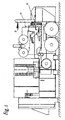
- Fig. 1 shows an application example of a packaging machine for cigarettes 10. Specifically, it is about the production of cigarette packs of the type folding box.
- a cigarette magazine 11 is an indispensable part of a packaging machine for cigarettes 10. In the area of this cigarette magazine 11, the cigarettes 10 produced elsewhere are introduced into the packaging process.
- the cigarette magazine 11 is formed in the upper part as a storage container 12 for cigarettes 10. Down close to the reservoir 12 cigarette bins 13. These are narrow, substantially upright channels in which the cigarettes 10 are conveyed downwards in upright rows, each one above the other.
- the cigarette trays 13 are bounded by shaft walls 14, which have a wedge-shaped decreasing wall thickness down.
- a plurality of cigarette shafts 13 form a shaft group or a shaft unit 15. From each of these shaft units 15 at the bottom of a cigarette group 16 is ejected in the longitudinal direction of the cigarette.
- the cigarette groups 16 are inserted in a cigarette conveyor directly adjacent to the shaft units 15, in the present example in a pocket of a cigarette turret 17.
- the cigarette magazine 11 shown in FIG. 1 is designed such that four shaft units 15 are provided four cigarette groups 16 are simultaneously ejected.
- the cigarette trays 13 are open at the top, that is, on the inlet side facing the storage container 12 for cigarettes 10.
- a cigarette supply 18 is constantly maintained by supplying cigarettes into the open-topped storage container 12.
- the cigarettes 10 are aligned next to each other, but without the formation of a specific formation. Under dead weight, the cigarettes 10 gradually reach the area of the cigarette shafts 13 and enter each one of the cigarette shafts 13 one by one.
- distribution organs are mounted at the upper ends of the shaft walls 14, namely profiled vibrating bars 19 rotating about their own longitudinal axis.
- the storage container 12 is bounded by side walls 20 which converge downwards in the direction of the shaft units 15, ie in a funnel shape.
- the shaft units 15 and outer walls 21 thereof are arranged in continuation of the side walls 20.
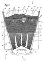
- a transverse cigarette is shown, hereinafter referred to as a false cigarette 22.
- parts of cigarettes, for example filters 23, may cause a disturbance.
- a (single) filter 23 or the like When the cigarette supply 18 with a defective cigarette 22, a (single) filter 23 or the like is conveyed down to the entrance side of the cigarette ducts 13, it follows that a number of cigarette ducts 13 are not supplied because of the transverse defective cigarette 22. This then results in that no or incomplete cigarette groups 16 are formed in this area.
- a control unit 24 is installed at a distance above the cigarette shafts 13 in the region of the cigarette supply 18. This preferably extends over the entire width of the storage container 12, that is, over the full width of the cigarette supply 18.
- the control unit 24 forms a plurality of upright inspection shafts 25 through which correctly aligned cigarettes 10 can pass during the downward movement.
- a transverse bad cigarette 22, a filter 23 or about an upright misalignment cigarette 22 can not pass through the inspection box 25, so remain before or above the control unit 24. From this situation, an error signal is derived, and as a result, the bad cigarette 22 and the filter 23 are eliminated.
- the cigarettes 10 in the reservoir 12 can continue to be moved downwardly outside the area of the false cigarette 22 or the filter 23, respectively.
- a sub-store 26 formed below the control unit 24 is accordingly filled up unchanged and is available over the full width of the cigarette magazine 11 to the cigarette shafts 13. Accordingly, despite a fault situation, the cigarette bays 13 are still completely supplied with cigarettes 10.
- the control unit 24 consists of a series of parallel guide webs 27. These are equally spaced from each other and juxtaposed and extend across the cigarette magazine 11 and through the reservoir 12 in the longitudinal direction of the cigarette 10.
- the cigarette magazine 11 is bounded transversely to the cigarettes 10 by a front wall 28 and a rear wall 29. The distance between the front wall 28 and the rear wall 29 is slightly larger than the length of a cigarette 10.
- the guide webs 27 of the control unit 24 are completely attached to the rear wall 29.
- the guide webs 27 delimit the substantially upright inspection shafts 25 whose width or free passage cross-section is slightly larger than the diameter of a cigarette 10.
- the aligned cigarettes 10 can therefore individually, successively slide through a control shaft 25 for partial stock 26.
- a cigarette 10 in Deformation for example, a transverse bad cigarette 22 or a single filter 23, however, can not pass a control shaft 25, but is above the control unit 24 retained by this (Fig. 2, Fig. 3).
- the guide webs 27 are angled or arc-shaped, so that due to the parallel arrangement of the guide webs 27 curved inspection bays 25 arise.
- the height of the inspection shafts 25 or the guide webs 27 is limited, namely chosen such that in each case about three to ten cigarettes 10 are received in a control shaft 25, in the embodiment according to FIGS. 3 to 5 three and a half cigarettes 10.
- a special feature is the monitoring of the inspection shafts 25. If a number of inspection shafts 25 - or at least a single inspection shaft 25 - does not permit cigarette flow due to a bad cigarette 22, the vacancy of the inspection shaft 25 is detected and a signal derived therefrom.
- each inspection pit 25 is equipped with at least one sensor 31. This is arranged laterally, namely on the rear wall 29. The sensor 31, in particular a reflection light barrier, each observes a control shaft 25 along its (horizontal) longitudinal extent.
- the sensors 31 are arranged in the upper region of the inspection shafts 25. If the sensor 31 or the light barrier is free - because of missing cigarettes 10 - an information signal is derived from this.
- the miss cigarette 22 and / or the filter 23 is manually removed.
- the front wall 28 of the cigarette magazine 11 has a flap 32 which is located in the region of the control unit and allows manual access to the wrong cigarette 22 - immediately above the control unit 24. After removing the Fehlzigarette 22 and closing the flap 32, the unhindered outflow of the cigarettes 10 in the area of the inspection wells 25 continue to run.
- the sensors 31 are arranged eccentrically within the inspection shafts 25, namely at the edge of a control shaft 25 or directly at a guide web 27 delimiting the inspection shaft 25.
- the sensors 31 are thus in the region of lateral, wedge-shaped gaps 33 between successive cigarettes 10 within the control shaft 25.
- the sensors 31 are cyclically acted upon by the cigarettes 10 passed by or the photocell temporarily released, namely, when a gap 33 is formed in the region of the light barrier. This will record a dynamic image of the cigarettes 10 being moved past in the correct position.
- a malposition is detected.
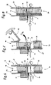
- control shafts 25 are formed, which have a greater height due to a corresponding configuration of the guide webs 27, so that approximately six to seven cigarettes 10 are received in a control shaft 25.
- the guide webs 27 consist of two at an obtuse angle to each other directed web legs 36, 37 of different lengths.
- the upper, shorter web leg 36 forms by chamfer 38 a broadened, funnel-like entry region for the cigarettes 10.
- Form and arrangement of the guide webs 27 also causes in this embodiment, that only correctly aligned cigarettes 10 can flow through the inspection shafts 25 (Fig. 11).
- An incorrectly positioned, for example, false cigarette 22 is fixed in the entry region of a control shaft 25 (FIG. 9).
- the sensors 31 are positioned approximately in the middle of the inspection shafts 25, for example in the region of the rounded transition from the upper web leg 36 to the lower web leg 37.
- inspection shafts 25 are shut off at their lower outlet end, by a movable closure member in the form of a rod or a closure plunger 34. Each inspection shaft 25 is associated with such a closure plunger 34. Upon detection of an error, the affected inspection slot 25 or the affected inspection slots 25 are shut off (FIGS. 3, 4, 9, 10).
- the shutter plungers 34 remain in this position until the error is cleared and the affected control shafts 25 are released.
- the correctly positioned cigarettes 10 enter the free control shafts 25 and initially rest on the shutter plungers 34 (FIGS. 4, 10) until they are in position the starting position (Fig. 8, Fig. 11) are moved back. Now, the cigarettes 10 can flow freely, namely to fill a funnel-shaped free space 35 below the affected by the Fehlzigarette 22 inspection wells 25th
- the closing plungers 34 are movable in the longitudinal direction, by mechanical or pneumatic actuation.
- the closure plunger 34 are inserted via the rear wall 29 of the cigarette magazine 11 in the respective inspection slot 25.
- the rear wall 29 is provided with openings for the passage of the shutter plunger 34.
- each closing plunger 34 is movable transversely to the cigarettes 10. In the starting position, each closing plunger 34 lies below the associated guide web 27 (FIG. 11). By transverse movement of the shutter plunger 34 reaches into the region of the associated inspection slot 25 (Fig. 9, Fig. 10).
- each shutter plunger 34 For transverse movement of each shutter plunger 34 is attached to a pivot web 39. This is moved along a pivot angle 39, whereby a corresponding transverse movement of the shutter plunger 34 (along a circular arc) is formed.
- the pivoting web 39 is mounted on a pivot pin 40, which in turn is rotatable by an actuator, in the present case by a transversely directed finger 41, acting on the free end of an actuator, namely a (pneumatic) plunger 42.
- This causes the Pivoting movement of the finger 41 by extension movement and thus the transverse movement of the shutter plunger 34.
- the opposite movement namely the return to the starting position, is carried out here by an elastic return member, namely by a tension spring 43rd
- the actuator with pivot web 39, pivot 40, finger 41, push rod 42 and tension spring 43 is attached to a bracket 44 which is fixed to the rear wall 29 of the cigarette magazine 11.
- each distributor bodies are arranged, namely about a longitudinal axis rotatable, in this case hexagonal Studttelstäbe 30. These ensure an orderly introduction of the cigarettes 10 in one of the inspection bays 25.
- the Studttelstäbe 30 are each arranged at a small distance exactly above a guide web 27 ,
Landscapes
- Engineering & Computer Science (AREA)
- Mechanical Engineering (AREA)
- Wrapping Of Specific Fragile Articles (AREA)
- Manufacturing Of Cigar And Cigarette Tobacco (AREA)
Claims (9)
- Dispositif pour l'emballage de groupes ordonnés d'objets en forme de bâtons, à savoir de groupes de cigarettes (16) comprenant des cigarettes (10), qui peuvent être prélevées d'un chargeur de cigarettes (11) par expulsion hors d'au moins une unité de conduits (15) constituée de conduits de cigarettes (13) sensiblement verticaux, une réserve de cigarettes (18), constituée de cigarettes (10) orientées les unes à côté des autres et les unes au-dessus des autres, étant formée au-dessus de l'unité de conduits (15) et une unité de contrôle (24), s'étendant transversalement, étant formée à partir d'une rangée de conduits de contrôle (25) sensiblement verticaux et étant disposée à distance au-dessus des conduits de cigarettes (13) dans la région de la réserve de cigarettes (18), le passage de cigarettes individuelles successives (10) à travers les conduits de contrôle (25) étant contrôlé par des capteurs (31) qui produisent un signal lorsque le flux de cigarettes (10) est interrompu dans la région d'au moins un conduit de contrôle (25), caractérisé par les caractéristiques suivantes :a) on associe à chaque conduit de contrôle (25) un capteur (31) d'une barrière lumineuse à réflexion agissant dans la direction longitudinale des cigarettes (10), pour détecter le contenu du conduit de contrôle (25),b) les capteurs (31) sont disposés au niveau d'une paroi arrière (29) du chargeur de cigarettes (11),c) les conduits de contrôle (25) sont réalisés sous forme cintrée ou coudée par façonnage correspondant des nervures de guidage (27) limitant les conduits de contrôle (25), de telle sorte qu'un passage de cigarettes (10) orientées verticalement ou de filtres (23) à travers un conduit de contrôle (25) soit exclu du fait de la forme géométrique de ce dernier,d) les nervures de guidage (27) se composent de deux branches de nervures (36, 37) orientées suivant un angle obtus l'une par rapport à l'autre, les capteurs (31) étant positionnés approximativement au centre des conduits de contrôle (25), à savoir dans le passage de la branche de nervure supérieure (36) à la branche de nervure inférieure (37).
- Dispositif selon la revendication 1, caractérisé en ce que la hauteur des conduits de contrôle (25) correspond à un diamètre de trois à dix cigarettes successives (10).
- Dispositif selon la revendication 1 ou selon l'une quelconque des autres revendications, caractérisé en ce que les conduits de contrôle (25) forment une région d'entrée supérieure en forme d'entonnoir pour les cigarettes (10), notamment par chanfreinage (38) au niveau des nervures de guidage (27).
- Dispositif selon la revendication 1 ou selon l'une quelconque des autres revendications, caractérisé en ce que le capteur (31) ou la barrière lumineuse est positionné(e) à l'intérieur d'un conduit de contrôle (25) de manière excentrée, de telle sorte que le capteur (31) ou son faisceau de contrôle soit actif dans la région des espaces (33) du côté des bords formés entre des cigarettes successives (10), un capteur (31) produisant un signal de panne lorsque le faisceau de contrôle n'est pas interrompu par des cigarettes pendant un intervalle de temps défini prolongé.
- Dispositif selon la revendication 1 ou selon l'une quelconque des autres revendications, caractérisé en ce que dans le cas d'une absence de flux de cigarettes (10) successives et positionnées en ordre à travers un conduit de contrôle (25), celui-ci peut être bloqué dans la région d'un orifice de sortie inférieur, notamment par un poussoir de fermeture mobile (34) pour chaque conduit de contrôle (25), le blocage du conduit de contrôle (25) pouvant être supprimé si des cigarettes (10) se présentent en position ordonnée à l'intérieur du conduit de contrôle concerné (25) après la réparation d'une panne.
- Dispositif selon la revendication 5 ou selon l'une quelconque des autres revendications, caractérisé en ce que les poussoirs de fermeture (34) peuvent être déplacés dans leur direction longitudinale ou dans la direction longitudinale des cigarettes (10), d'une position en dehors d'un conduit de contrôle (25) dans une position de blocage à l'intérieur du conduit de contrôle (25) concerné.
- Dispositif selon la revendication 6 ou selon l'une quelconque des autres revendications, caractérisé en ce que les poussoirs de fermeture (34) sont disposés dans leur position de départ en dessous d'une nervure de guidage associée (27) dans la direction longitudinale de cette dernière et peuvent être déplacés par un mouvement transversal dans la région du conduit de contrôle concerné (25).
- Dispositif selon la revendication 7 ou selon l'une quelconque des autres revendications, caractérisé en ce que chaque poussoir de fermeture (34) est disposé sur une nervure pivotante (39) et peut être déplacé transversalement par un mouvement de pivotement de la nervure pivotante (39).
- Dispositif selon la revendication 1 ou selon l'une quelconque des autres revendications, caractérisé en ce qu'une paroi verticale du chargeur de cigarettes (11), notamment une paroi avant (28), présente dans la région de l'unité de contrôle (24) un volet (32) qui peut être actionné dans le cas d'un signal de panne pour enlever des cigarettes non conformes (22) ou des filtres individuels (23).
Applications Claiming Priority (2)
| Application Number | Priority Date | Filing Date | Title |
|---|---|---|---|
| DE2002159219 DE10259219A1 (de) | 2002-12-17 | 2002-12-17 | Vorrichtung zum Verpacken von Zigaretten |
| DE10259219 | 2002-12-17 |
Publications (3)
| Publication Number | Publication Date |
|---|---|
| EP1431184A2 EP1431184A2 (fr) | 2004-06-23 |
| EP1431184A3 EP1431184A3 (fr) | 2005-11-16 |
| EP1431184B1 true EP1431184B1 (fr) | 2007-10-24 |
Family
ID=32336438
Family Applications (1)
| Application Number | Title | Priority Date | Filing Date |
|---|---|---|---|
| EP20030027917 Expired - Lifetime EP1431184B1 (fr) | 2002-12-17 | 2003-12-04 | Dispositif pour l'emballage des cigarettes |
Country Status (2)
| Country | Link |
|---|---|
| EP (1) | EP1431184B1 (fr) |
| DE (2) | DE10259219A1 (fr) |
Families Citing this family (3)
| Publication number | Priority date | Publication date | Assignee | Title |
|---|---|---|---|---|
| ITBO20040719A1 (it) * | 2004-11-19 | 2005-02-19 | Gd Spa | Dispositivo di alimentazione gruppi ordinati di sigarette |
| CN105883043A (zh) * | 2016-06-13 | 2016-08-24 | 昆明红实科技有限公司 | Gdx2包装机烟库烟支预整理装置 |
| CN106081236A (zh) * | 2016-08-16 | 2016-11-09 | 河南新平科烟草机械有限公司 | 一种包装机烟支预整理装置 |
Family Cites Families (9)
| Publication number | Priority date | Publication date | Assignee | Title |
|---|---|---|---|---|
| DE2709700A1 (de) | 1977-03-05 | 1979-01-25 | Hauni Werke Koerber & Co Kg | Vorrichtung zum fuellen von schragen mit stabfoermigen artikeln der tabakverarbeitenden industrie |
| DE2826539C2 (de) * | 1977-06-30 | 1984-09-27 | Molins Ltd., London | Zigarettenzuführvorrichtung |
| IT1172946B (it) | 1983-12-20 | 1987-06-18 | Sasib Spa | Dispositivo per la formazione di gruppi ordinati di sigarette in macchine impacchettatrici di sigarette |
| DE3609094A1 (de) * | 1985-04-13 | 1986-10-23 | Maschinenfabrik Fr. Niepmann GmbH u. Co, 5820 Gevelsberg | Vorrichtung zum pruefen der qualitaet von stabfoermigen, zylindrischen gegenstaenden, vorzugsweise zigaretten |
| DE3729213A1 (de) * | 1987-09-02 | 1989-03-16 | Focke & Co | Vorrichtung zum pruefen von zigaretten und aussondern fehlerhafter zigaretten |
| DE3812689A1 (de) * | 1988-04-16 | 1989-11-02 | Focke & Co | Vorrichtung zum pruefen von zigaretten |
| US5259402A (en) | 1991-12-04 | 1993-11-09 | Philip Morris Incorporated | Cigarette hopper vane jam prevention device |
| IT1308976B1 (it) | 1999-01-15 | 2002-01-15 | Gd Spa | Metodo per la formazione di gruppi di sigarette in una macchinaimpacchettatrice di sigarette. |
| DE19903777A1 (de) * | 1999-02-01 | 2000-08-03 | Focke & Co | Verfahren und Vorrichtung zum Detektieren sowie Beseitigen fehlerhafter und/oder fehlerhaft positionierter Zigaretten |
-
2002
- 2002-12-17 DE DE2002159219 patent/DE10259219A1/de not_active Withdrawn
-
2003
- 2003-12-04 EP EP20030027917 patent/EP1431184B1/fr not_active Expired - Lifetime
- 2003-12-04 DE DE50308455T patent/DE50308455D1/de not_active Expired - Lifetime
Also Published As
| Publication number | Publication date |
|---|---|
| DE50308455D1 (de) | 2007-12-06 |
| EP1431184A2 (fr) | 2004-06-23 |
| DE10259219A1 (de) | 2004-07-15 |
| EP1431184A3 (fr) | 2005-11-16 |
Similar Documents
| Publication | Publication Date | Title |
|---|---|---|
| DE60301642T2 (de) | Verfahren und Vorrichtung zum Selektieren und Zuführen von Artikeln | |
| DE60121670T2 (de) | Vorrichtung zum Formen von Zigarettengruppen | |
| EP1026079B1 (fr) | Procédé et dispositif pour détecter et rejeter des cigarettes défectueuses ou mal positionées | |
| EP0249791B1 (fr) | Procédé et dispositif pour séparer des cigarettes défectueuses en relation avec une machine d'emballage de cigarettes | |
| DE19617014A1 (de) | Verfahren und Vorrichtung zum Nachfüllen von Füllgut in Näpfe einer Folienbahn | |
| EP2922758A1 (fr) | Procédé et dispositif de remplissage d'emballages avec des produits | |
| DE3344907C2 (de) | Vorrichtung zum Zuführen von Zigaretten | |
| EP2028142A1 (fr) | Cartouche pour tiges de stockage en vue de la réception de produits en forme de saucisse et procédé de guidage des tiges de stockage pour un remplissage par des produits en forme de saucisse | |
| DE3808964A1 (de) | Vorrichtung zum absondern von zigaretten | |
| EP0198282B1 (fr) | Dispositif pour l'examen de la qualité d'articles cylindriques en forme de bâtonnets, notamment de cigarettes | |
| DE2419445A1 (de) | Verpackungsvorrichtung zum verpacken von rollen, insbesondere muenzrollen | |
| DE3930917C2 (de) | Vorrichtung zum Absondern von Zigaretten | |
| DE2852801A1 (de) | Vorrichtung zum fuellen von behaeltern | |
| EP0231779B1 (fr) | Procédé et dispositif pour contrôler des cigarettes | |
| EP0141322A1 (fr) | Dispositif pour l'emballage de cigarettes | |
| EP1431184B1 (fr) | Dispositif pour l'emballage des cigarettes | |
| DE1548210A1 (de) | Maschine zur Pruefung von Glasbehaeltern od.dgl. | |
| DE3509711C2 (de) | Vorrichtung zur Zufuhr von Zigaretten zur Umhüllungsstrecke einer Verpackungsmaschine | |
| DE4314878A1 (de) | Umwickel-, Schachtelbefüll- und Schließautomat für Folien-Rollenware | |
| DE4205879C1 (fr) | ||
| DE3116156C2 (de) | Verfahren zum Bilden von Zigarettengruppen und Vorrichtung zur Durchführung des Verfahrens | |
| DE3543232A1 (de) | Vorrichtung fuer die zufuhr der zigaretten zur umhuellungsstrecke einer verpackungsmaschine | |
| WO1983001020A1 (fr) | Procede et dispositif pour ranger des pieces a usiner | |
| EP0307661B1 (fr) | Dispositif pour contrôler des cigarettes et séparer les cigarettes défectueuses | |
| DE3723407C2 (de) | Verfahren zur Bildung von Gruppen von Filterzigaretten in einer Verpackungsmaschine |
Legal Events
| Date | Code | Title | Description |
|---|---|---|---|
| PUAI | Public reference made under article 153(3) epc to a published international application that has entered the european phase |
Free format text: ORIGINAL CODE: 0009012 |
|
| AK | Designated contracting states |
Kind code of ref document: A2 Designated state(s): AT BE BG CH CY CZ DE DK EE ES FI FR GB GR HU IE IT LI LU MC NL PT RO SE SI SK TR |
|
| AX | Request for extension of the european patent |
Extension state: AL LT LV MK |
|
| RAP1 | Party data changed (applicant data changed or rights of an application transferred) |
Owner name: FOCKE & CO. (GMBH & CO. KG) |
|
| PUAL | Search report despatched |
Free format text: ORIGINAL CODE: 0009013 |
|
| AK | Designated contracting states |
Kind code of ref document: A3 Designated state(s): AT BE BG CH CY CZ DE DK EE ES FI FR GB GR HU IE IT LI LU MC NL PT RO SE SI SK TR |
|
| AX | Request for extension of the european patent |
Extension state: AL LT LV MK |
|
| RIC1 | Information provided on ipc code assigned before grant |
Ipc: 7B 65B 19/28 B Ipc: 7B 65B 19/30 A Ipc: 7A 24C 5/34 B |
|
| TPAC | Observations by third parties |
Free format text: ORIGINAL CODE: EPIDOSNTIPA |
|
| 17P | Request for examination filed |
Effective date: 20060125 |
|
| AKX | Designation fees paid |
Designated state(s): DE GB IT |
|
| GRAP | Despatch of communication of intention to grant a patent |
Free format text: ORIGINAL CODE: EPIDOSNIGR1 |
|
| GRAS | Grant fee paid |
Free format text: ORIGINAL CODE: EPIDOSNIGR3 |
|
| GRAA | (expected) grant |
Free format text: ORIGINAL CODE: 0009210 |
|
| AK | Designated contracting states |
Kind code of ref document: B1 Designated state(s): DE GB IT |
|
| REG | Reference to a national code |
Ref country code: GB Ref legal event code: FG4D Free format text: NOT ENGLISH |
|
| REF | Corresponds to: |
Ref document number: 50308455 Country of ref document: DE Date of ref document: 20071206 Kind code of ref document: P |
|
| GBT | Gb: translation of ep patent filed (gb section 77(6)(a)/1977) |
Effective date: 20071121 |
|
| PLBE | No opposition filed within time limit |
Free format text: ORIGINAL CODE: 0009261 |
|
| STAA | Information on the status of an ep patent application or granted ep patent |
Free format text: STATUS: NO OPPOSITION FILED WITHIN TIME LIMIT |
|
| 26N | No opposition filed |
Effective date: 20080725 |
|
| PGFP | Annual fee paid to national office [announced via postgrant information from national office to epo] |
Ref country code: GB Payment date: 20151202 Year of fee payment: 13 |
|
| GBPC | Gb: european patent ceased through non-payment of renewal fee |
Effective date: 20161204 |
|
| PG25 | Lapsed in a contracting state [announced via postgrant information from national office to epo] |
Ref country code: GB Free format text: LAPSE BECAUSE OF NON-PAYMENT OF DUE FEES Effective date: 20161204 |
|
| PGFP | Annual fee paid to national office [announced via postgrant information from national office to epo] |
Ref country code: DE Payment date: 20171220 Year of fee payment: 15 |
|
| PGFP | Annual fee paid to national office [announced via postgrant information from national office to epo] |
Ref country code: IT Payment date: 20171221 Year of fee payment: 15 |
|
| REG | Reference to a national code |
Ref country code: DE Ref legal event code: R119 Ref document number: 50308455 Country of ref document: DE |
|
| PG25 | Lapsed in a contracting state [announced via postgrant information from national office to epo] |
Ref country code: DE Free format text: LAPSE BECAUSE OF NON-PAYMENT OF DUE FEES Effective date: 20190702 Ref country code: IT Free format text: LAPSE BECAUSE OF NON-PAYMENT OF DUE FEES Effective date: 20181204 |