EP1423260B1 - Machine a comprimer rotative et son procede de nettoyage - Google Patents
Machine a comprimer rotative et son procede de nettoyage Download PDFInfo
- Publication number
- EP1423260B1 EP1423260B1 EP01965500A EP01965500A EP1423260B1 EP 1423260 B1 EP1423260 B1 EP 1423260B1 EP 01965500 A EP01965500 A EP 01965500A EP 01965500 A EP01965500 A EP 01965500A EP 1423260 B1 EP1423260 B1 EP 1423260B1
- Authority
- EP
- European Patent Office
- Prior art keywords
- compression unit
- die
- punches
- press
- cleaning
- Prior art date
- Legal status (The legal status is an assumption and is not a legal conclusion. Google has not performed a legal analysis and makes no representation as to the accuracy of the status listed.)
- Expired - Lifetime
Links
Images


Classifications
-
- B—PERFORMING OPERATIONS; TRANSPORTING
- B30—PRESSES
- B30B—PRESSES IN GENERAL
- B30B11/00—Presses specially adapted for forming shaped articles from material in particulate or plastic state, e.g. briquetting presses, tabletting presses
- B30B11/02—Presses specially adapted for forming shaped articles from material in particulate or plastic state, e.g. briquetting presses, tabletting presses using a ram exerting pressure on the material in a moulding space
- B30B11/08—Presses specially adapted for forming shaped articles from material in particulate or plastic state, e.g. briquetting presses, tabletting presses using a ram exerting pressure on the material in a moulding space co-operating with moulds carried by a turntable
-
- B—PERFORMING OPERATIONS; TRANSPORTING
- B08—CLEANING
- B08B—CLEANING IN GENERAL; PREVENTION OF FOULING IN GENERAL
- B08B3/00—Cleaning by methods involving the use or presence of liquid or steam
- B08B3/02—Cleaning by the force of jets or sprays
-
- B—PERFORMING OPERATIONS; TRANSPORTING
- B08—CLEANING
- B08B—CLEANING IN GENERAL; PREVENTION OF FOULING IN GENERAL
- B08B3/00—Cleaning by methods involving the use or presence of liquid or steam
- B08B3/04—Cleaning involving contact with liquid
-
- B—PERFORMING OPERATIONS; TRANSPORTING
- B30—PRESSES
- B30B—PRESSES IN GENERAL
- B30B15/00—Details of, or accessories for, presses; Auxiliary measures in connection with pressing
- B30B15/0023—Drive arrangements for movable carriers, e.g. turntables
-
- B—PERFORMING OPERATIONS; TRANSPORTING
- B30—PRESSES
- B30B—PRESSES IN GENERAL
- B30B15/00—Details of, or accessories for, presses; Auxiliary measures in connection with pressing
- B30B15/0082—Dust eliminating means; Mould or press ram cleaning means
-
- B—PERFORMING OPERATIONS; TRANSPORTING
- B30—PRESSES
- B30B—PRESSES IN GENERAL
- B30B15/00—Details of, or accessories for, presses; Auxiliary measures in connection with pressing
- B30B15/02—Dies; Inserts therefor; Mounting thereof; Moulds
- B30B15/026—Mounting of dies, platens or press rams
-
- B—PERFORMING OPERATIONS; TRANSPORTING
- B30—PRESSES
- B30B—PRESSES IN GENERAL
- B30B15/00—Details of, or accessories for, presses; Auxiliary measures in connection with pressing
- B30B15/02—Dies; Inserts therefor; Mounting thereof; Moulds
- B30B15/028—Loading or unloading of dies, platens or press rams
-
- B—PERFORMING OPERATIONS; TRANSPORTING
- B30—PRESSES
- B30B—PRESSES IN GENERAL
- B30B15/00—Details of, or accessories for, presses; Auxiliary measures in connection with pressing
- B30B15/32—Discharging presses
-
- A—HUMAN NECESSITIES
- A61—MEDICAL OR VETERINARY SCIENCE; HYGIENE
- A61J—CONTAINERS SPECIALLY ADAPTED FOR MEDICAL OR PHARMACEUTICAL PURPOSES; DEVICES OR METHODS SPECIALLY ADAPTED FOR BRINGING PHARMACEUTICAL PRODUCTS INTO PARTICULAR PHYSICAL OR ADMINISTERING FORMS; DEVICES FOR ADMINISTERING FOOD OR MEDICINES ORALLY; BABY COMFORTERS; DEVICES FOR RECEIVING SPITTLE
- A61J3/00—Devices or methods specially adapted for bringing pharmaceutical products into particular physical or administering forms
- A61J3/10—Devices or methods specially adapted for bringing pharmaceutical products into particular physical or administering forms into the form of compressed tablets
Definitions
- the present invention relates to a compression unit and a rotary tablet press comprising said compression unit.
- the said rotary tablet press comprises a housing, a rotary die table detachably connected to a drive shaft arranged in the housing for rotation of the die table, a number of dies arranged circumferentially in the die table, each die being associated with at least a first punch having a first end receivable in the die through an opening of the die and arranged for compression of a powder or granular material in the die by reciprocation of the punch, and at least a cam for cooperation with a second end of the punches in order to effect axial displacement of the punches by rotation of the die table, whereby a compression unit detachably mounted in the housing comprises the die table with punches, a feeding device for the supply of material to be compressed into the dies, and a tablet discharge device for removal of compressed material in the form of tablets.
- EP 0288 798 describes a tablet press having a die table rotatable about a vertical axis, each die having associated top and bottom punches receivable therein and the punches being guided by top and bottom cams, respectively, whereby the cams are stationary relative to the press housing.
- the die table with punches and cams is detachable as a unit from the press housing.
- EP 1 050 399 describes a rotary tablet press of the same type, in which the exchange of components between batches has been further improved by the provision of a U-shaped rigid connection frame between the top and bottom cams.
- the connection frame is detachably connected with the press housing, whereby the unit comprising connection frame, die table, punches and cams may be removed in a single operation by disconnection of the connection frame from the housing and disengagement of the die table from its drive shaft.
- auxiliary equipment such as powder feeder and tablet outlet
- EP 0 637 507 describes a rotary tablet press provided with equipment for so-called washing-in-place (WIP) in the form of spray nozzles for spraying of washing agent onto the die table and associated components as well as suction pipes for draining off the washing agent.
- WIP washing-in-place
- washing-in-place operations by means of the spray nozzles also take long time, for instance up to eight hours, mainly due to long drying and cooling cycles after the wash cycle. During these cycles, the tablet press is out of production.
- the equipment required for washing-in-place comprises several spray nozzles and suction pipes, etc., and consequently increases the price of the tablet press considerably.
- US 4,259,049 describes a rotary tablet press in which some of the negative effects of dust generation have been alleviated during production.
- the leading end portions of the punches are surrounded by cuffs, through which gas is blown towards the front ends of the punches to prevent deposition of dust on the punch surfaces.
- said cuffs are surrounded by suction chambers provided by stationary mounted shields.
- change-over as well as cleaning of the machine between batches are even more complicated and consequently time-consuming, as the shields have to be removed manually to access the dies and associated punches.
- this tablet press does not provide for removal of the die table and punches as a unit, these components must subsequently be disassembled also manually and one by one, all operations which are very time-consuming and must be done during standstill of the machine.
- the object of the present invention is to provide a compression unit for releasable attachment is a housing of a rotary tablet press by which the time required for cleaning of the press between batches is reduced compared to prior art presses and by which the risk of contamination of the surrounding environment as well as exposure of the operator to the product may be reduced to a minimum.
- the compression unit is characterized in that it encloses each die opening and its corresponding first punch end in a chamber, in that the feeding device and the tablet discharge device are enclosed, in that the feeding device communicates with an inlet for detachable connection with an external supply channel, and in that the tablet discharge device communicates with an outlet.
- the compression unit may between batches fast and easily in a single operation be exchanged for an already cleaned unit, without having to clean supplementary parts of the tablet press, other than the supply channel, and without the operator being exposed to the product.
- the supply channel may be readily cleaned by means of well known techniques, such as cleaning-in-place (CIP) by means of spray nozzles, the compression unit requires a much more thorough cleaning procedure.
- CIP cleaning-in-place
- the unit may be transported to a dedicated cleaning station without contamination of the environment.
- the cleaning of the unit may be carried out manually, possibly in an isolator, without delaying the production, as another already cleaned unit is mounted in the tablet press for the production, but the cleaning may advantageously be automated.
- a dedicated automated cleaning station it is possible to clean the compression unit much more thoroughly and also faster than it is possible in the known tablet presses provided with washing-in-place equipment, because the unit is separated from its surroundings in the press, so that the operation of the cleaning equipment is not restricted by the limited space in the press.
- the function of the tablet press is not affected by the presence of the cleaning equipment.
- the unit may be manipulated much more extensively by dedicated equipment, for example the punches may be moved vigorously in their dies during spraying with cleaning agent, the tablet feeder may be moved or even disassembled automatically, etc.
- one automated cleaning station equipped with sophisticated manipulators and spray nozzles is able to serve several tablet presses which do only have to be out of production during a very reduced time for exchange of the compression unit between batches.
- the expenses of cleaning equipment are much reduced compared to tablet presses provided with cleaning-in-place equipment, because in the latter case, each press must be provided with expensive cleaning equipment.
- the second punch ends are accessible for actuation from outside the compression unit.
- actuation means such as rollers and possibly the cams
- this equipment does not have to be replaced with the compression unit between batches
- possible lubrication of the actuation means cannot result in contamination of the product with lubricants.
- the compression unit comprises a casing surrounding at least part of the die table, the feeding device and the tablet discharge device, and the inlet and the tablet outlet are arranged in a wall of the casing.
- the casing of the compression unit may be provided with a releasable opening mechanism for opening of at least one door in the casing or detachment of at least a part of the casing from the compression unit in order to facilitate cleaning of the unit.
- the opening of the casing may advantageously be performed automatically in a closed chamber in an automatic cleaning station.
- each die is associated with first and second punches arranged for reciprocation in a direction parallel with the axis of rotation of the die table, the first and second punches are received in guides on either side of the die, respectively, said guides being accommodated in a rotary turret comprising the die table, the casing comprised by the compression unit surrounds the periphery of the turret and is sealed against the latter by means of seals permitting rotation of the turret in relation to the casing, and the casing has a bracket connected rotatably with the turret by means of a bearing.
- the second punch ends may project from opposed ends of the turret for actuation, and the compression area may be delimited by the periphery of the turret and the surrounding stationary casing.
- a tight sealing between the turret and the casing may be achieved as a result of the bearing centring the casing in relation to the turret.
- the punches may advantageously be sealed against their guides at the first punch ends by means of seals permitting axial displacement of the punches in the guides, such as lip seals or bellows seals. This prevents product from entering the guide bores and thereby effecting the operation of the punches negatively.
- the compression unit has auxiliary devices communicating with the press housing via releasable connections, such as dust aspiration nozzles communicating with the press housing via releasable tube connections, a powder feeder driven through a releasable shaft connection by means of a drive accommodated in the tablet press housing, a lubrication system communicating with the press housing via releasable tube connections, etc.
- auxiliary devices communicating with the press housing via releasable connections, such as dust aspiration nozzles communicating with the press housing via releasable tube connections, a powder feeder driven through a releasable shaft connection by means of a drive accommodated in the tablet press housing, a lubrication system communicating with the press housing via releasable tube connections, etc.
- releasable conduit connections between inlets or outlets of the compression unit and corresponding channels in the press housing are provided with a closure mechanism on either side of a disconnection mechanism.
- the releasable conduit connections are in the form of so-called double ball valves.
- a ball valve is provided on either side of a disconnection mechanism.
- the releasable conduit connections are preferably in the form of so-called split valves having two mating valve members, such as split butterfly valves.
- This type of connection permits closing of the conduit passage and subsequently separation of the two valve parts, whereby each of the two mating valve members remains in its corresponding valve part closing the valve opening, practically without any leakage of the product to the surroundings.
- releasable conduit connections may also be in the form of plastic tubes. This permits closing the connections by squeezing the plastic tube and heating it up, whereby it is welded together. The tube may then be cut through in the middle of the weld so that the two resulting tube ends are sealed.
- a number of top cams for cooperation with first punches and a number of bottom cams for cooperation with second punches are mounted on the compression unit for removal from the press housing together with the compression unit.
- a number of top cams for cooperation with first punches are mounted on the compression unit for removal from the press housing together with the compression unit, and a number of bottom cams for cooperation with second punches are mounted in the press housing so that the second punches are releasable from the bottom cams for removal from these together with the compression unit.
- a top cam for cooperation with punches is mounted adjustably on the compression unit.
- the cam in order to move the punches in a way specifically suited for the cleaning operation, for instance they may be moved more vigorously by cleaning than by the tablet press operation.
- a compression roller for cooperation with first punches is supported above the compression unit by a height adjustable block, and the height adjustable block has a coupling element for engagement with a corresponding coupling element on the compression unit.
- the height adjustable block has a coupling element for engagement with a corresponding coupling element on the compression unit.
- the press housing is provided with a swivel arm pivotal about a vertical axis and provided with a coupling element for engagement with a corresponding coupling element on the compression unit.
- the compression unit may after elevation from the drive shaft be swung out of the press housing and placed on a carriage for transfer to a cleaning station.
- the press housing is provided with a separate support for the feeding device, the feeding device is displaceable in relation to the compression unit, and said support has a snap coupling mechanism such as a pneumatic coupling mechanism for connection with the feeding device.
- the support provides for correct positioning of the feeding device in relation to the die table and the snap coupling mechanism ensures fast and easy disconnection of the feeding device from the support when the compression unit is to be removed.
- the present invention also relates to a rotary tablet press comprising the previously defined compression unit.
- the compression unit comprises a casing surrounding at least part of the die table, the feeding device and the tablet discharge device, the inlet and a tablet outlet are arranged in a wall of the casing, and the casing of the compression unit is provided with a releasable opening mechanism for opening of at least one door in the casing or detachment of at least a part of the casing from the compression unit.
- the invention further relates a cleaning station for automated cleaning of a compression unit detached from a rotary tablet press, the compression unit comprising a number of dies arranged circumferentially in a rotary die table, each die being associated with at least a first punch having a first end receivable in the die through an opening of the die, a feeding device for the supply of material to be compressed into the dies, and a tablet discharge device for removal of compressed material in the form of tablets.
- the cleaning station according to the invention is characterized in that it comprises at least two separate cleaning fluid devices each having a connection piece for detachable connection with a corresponding connection piece provided on the compression unit and communicating with an enclosure of the compression unit, the cleaning fluid devices being arranged for the supply of cleaning fluid to the compression unit and for the drainage of cleaning fluid from the compression unit.
- At least one of the cleaning fluid devices is provided with a cleaning fluid spray nozzle arranged for automatic introduction through the corresponding connection piece on the compression unit.
- the cleaning fluid may be aimed more directly at the components to be cleaned, thereby ensuring a more effective cleaning.
- the invention moreover relates a cleaning station for automated cleaning of a compression unit detached from a rotary tablet press
- the compression unit comprising a number of dies arranged circumferentially in a rotary die table, each die being associated with at least a first punch having a first end receivable in the die through an opening of the die, a feeding device for the supply of material to be compressed into the dies, and a tablet discharge device for removal of compressed material in the form of tablets
- the cleaning station comprising a cleaning chamber for accommodation of the compression unit during cleaning, and the cleaning chamber being provided with at least a cleaning fluid spray nozzle,
- cleaning station is characterized in that it comprises an automatic manipulator for opening at least partially a chamber which is comprised by the compression unit and which before opening encloses at least a die opening and its corresponding first punch end.
- the cleaning fluid may therefore be sprayed more directly at the components to be cleaned.
- the cleaning chamber may be adapted so that the second punch ends are accessible for actuation from outside the cleaning chamber. This may be advantageous, if the second punch ends should be actuated during cleaning, but preferably kept out of contact with the cleaning fluid, thereby avoiding to relubricate these after replacement of the compression unit in the tablet press.
- the cleaning station comprises a drive shaft for detachable connection to the rotary die table of the compression unit for rotation of the die table during cleaning in order to effect axial displacement of the punches.
- the cleaning station comprises an automatic manipulator for adjustment of a cam of the compression unit or the cleaning station comprises at least a cam for cooperation with a second end of the punches in order to effect axial displacement of the punches by rotation of the die table.
- the cleaning station comprises an automatic manipulator for opening and/or moving a powder feeding device and/or a tablet discharge device of the compression unit. This ensures effective cleaning of the internal components of the powder feeding device and/or the tablet discharge device.
- the invention additionally relates a method of manufacturing tablets or the like in a rotary tablet press having a press housing and a compression unit comprising a number of dies arranged circumferentially in a rotary die table, each die being associated with at least a first punch having a first end receivable in the die through an opening of the die, a feeding device for the supply of material to be compressed into the dies, and a tablet discharge device for removal of compressed material in the form of tablets or the like, whereby the compression unit between batches of tablets is detached from the press housing and transferred to a cleaning station.
- the method according to the invention is characterized by that during the pressing of tablets or the like and during the transfer of the compression unit to the cleaning station each die opening and its corresponding first punch end are maintained enclosed in a chamber of the compression unit and the feeding device and the tablet discharge device are maintained enclosed.
- the invention further relates to a method of cleaning a compression unit detached from a rotary tablet press, the compression unit comprising a number of dies arranged circumferentially in a rotary die table, each die being associated with at least a first punch having a first end receivable in the die through an opening of the die, a feeding device for the supply of material to be compressed into the dies, and a tablet discharge device for removal of compressed material in the form of tablets, which method is characterized by that at least one separate cleaning fluid device by means of a connection piece is connected with a corresponding connection piece provided on the compression unit and communicating with an enclosure of the compression unit, and by that subsequently cleaning fluid is supplied to the enclosure of the compression unit from the at least one cleaning fluid device.
- at least two cleaning fluid devices are employed, whereby cleaning fluid is drained from the enclosure to one of the cleaning fluid devices.
- the cleaning fluid may be circulated through the enclosure of the compression unit in alternating directions.
- the invention also relates to a method of cleaning a compression unit detached from a rotary tablet press, the compression unit comprising a number of dies arranged circumferentially in a rotary die table, each die being associated with at least a first punch having a first end receivable in the die through an opening of the die, a feeding device for the supply of material to be compressed into the dies, and a tablet discharge device for removal of compressed material in the form of tablets, whereby the compression unit is placed in a closed cleaning chamber, which method is characterized by that, in the closed cleaning chamber, a chamber comprised by the compression unit and enclosing a die opening and its corresponding first punch end is opened, whereupon the compression unit is cleaned by means of cleaning fluid.
- the punches may be removed from the compression unit. This facilitates effective cleaning, as product trapped between the punches and their corresponding guides easier may be removed during cleaning.
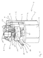
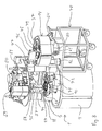
- Fig. 1 shows a rotary tablet press 1 for compression of a feedstock in the form of powder or granular material into tablets, compacts or the like.
- the press shown is of a type suitable for use in the pharmaceutical industry, but the press according to the invention may as well be a so-called industrial press employed in the production of a variety of different products, such as vitamins, pet food, detergents, explosives, ceramics, batteries, balls, bearings, nuclear fuels, etc.
- the rotary tablet press 1 has a press housing 2 comprising an internal frame 3, which supports various components located in the housing 2, and an outer lining 4, which is shown only at a lower section 5 of the press.
- the press housing 2 is composed of three sections, which are located on top of each other and are separated by means of partition walls.
- the lower section, designated the drive section 5, is separated from a central section, designated the compression section 6, by a lower partition wall 7, and the compression section 6 is separated from an upper section, designated the accessory section 8, by an upper partition wall 9.
- the drive section 5 comprises a not shown electrical drive motor driving a vertical drive shaft 10 projecting up through a central opening in the lower partition wall 7 and having at its upper end a coupling part 11 for detachable connection with a rotary turret 12 located in a casing 13 of a compression unit 14 which is arranged detachably in the compression section 6 of the press housing 2, see also Figs. 2 and 8.
- the rotary turret 12 comprises a die table 15 having a number of dies arranged evenly distributed along its circumference, each die having the form of a bore 16 arranged with its axis parallel to the vertical rotational axis of the turret 12.
- On either side of the die table 15 are arranged top and bottom punches 17, 18, respectively, in corresponding guides 19, 20 accommodated in the turret 12 so that a first end 21, 22 of each punch 17, 18 is able to enter a corresponding die 16 by displacement of the punch in its guide 19, 20 in order to compress material in the die.
- the punches 17, 18 are sealed against their guides 19, 20 at the end of these facing the die table 15 by means of lip seals 87.
- a bellows seal for instance of silicone, may be employed.
- a second end 23, 24 of each punch 17, 18 is cooperating with top and bottom cams 25, 26, respectively, arranged stationary in relation to the press housing 2 in order to effect axial displacement of the punches by rotation of the turret 12.
- Each second end 23, 24 of the punches 17, 18 has a head 27 with an upward side 28 and a downward side 29 for sliding against corresponding surfaces 30, 31 on the cams 25, 26 so that the punches may be pushed both in upward and downward direction as a result of the differing height positions of the cam surfaces 30, 31 in the circumferential direction of the turret.
- the top rollers 32, 33 are journalled in height adjustable blocks 34, 35 arranged in the housing 2.
- the bottom cams 26 are mounted on a part of the frame 3 in such a way that they may be opened to permit removal of the bottom punches 18 together with the compression unit 14 from the housing 2, for instance by removal of that part of the bottom cams bearing the downward cam surfaces 30. However, the bottom cams 26 may also be mounted on the compression unit 14 so that they will be removed together with this.
- Each bottom punch 18 is provided with a brake system 36 in the form of a spring-loaded ball provided in a bore perpendicular to the guide of the punch, whereby the ball is pressed against the punch circumference and thereby prevents the punch from falling down when leaving the cam where the compression rollers 32, 33 are to take over pressing, as well as after removal of the compression unit from the housing 2.
- brake systems of different construction well-known in the art may also be employed.
- the top cams 25 are mounted in the compression unit 14 for removal together with this from the press housing 2 and are by means of a bracket 37 connected rigidly to the casing 13 of the compression unit.
- the casing 13 is in the mounted position of the compression unit 14 in the press housing 2 held stationary in relation to the latter by means of a not shown releasable connection with the housing.
- the cams 25 are by means of a roller and/or ball bearing 38 supported by the turret 12.
- the casing 13 of the compression unit 14 comprises a top wall 39, a bottom wall 40 and more side walls 41.
- a number of the side walls 41 may be detached from the compression unit 14 in order to gain access to the internal components of the unit for exchange of components at change-over between batches of different products, for cleaning or for maintenance, see also Fig. 3, in which one of the side walls has been removed.
- the top and bottom walls 39, 40 are substantially plane, each having a central circular opening 42, 43 sealed rotatably against the periphery of the turret 12 by means of a seal 44, 45, such as a lip seal.
- the above-mentioned centring of the casing 13 in relation to the turret 12 by means of bearings assures proper function of the seals 44, 45.
- Most of the side walls 41 have a curved configuration in order to give the casing 13 a substantially round shape seen from above, thereby obtaining a compact unit and avoiding too many corners where dust can build up in the casing during production.
- the compression unit 14 is provided with a feeding device in the form of a well-known double rotary feeder 48 with two not shown rotary paddles located in a feeder housing 49 and driven by means of separate drive motors 50, 51 located in the accessory section 8 of the press housing 2 and providing for independent speed setting of the paddles, see also Fig. 1.
- the feeder housing 49 is open against the die table so that the paddles may ensure proper filling of the dies 16 with feedstock.
- the paddle drive motors 50, 51 are mechanically connected to the paddles by means of drive shafts 52, 53 of the cardan type, the latter being detachably connected to drive coupling parts 54, 55 located in the top wall 39 of the compression unit 14 and drivingly connected to the respective paddles in the feeder 48.
- the drive coupling parts 54, 55 may also be located on the feeder housing 49 so that the drive shafts 52, 53 protrude through the top wall 39. After disconnecting the drive shafts 52, 53 from the drive coupling parts 54, 55, the through holes in the top wall 39 may then be closed by means of plugs. Which solution is to be chosen may depend on the toxicity of the product to be handled.
- the feeder housing 49 has a feedstock inlet that opens through the top wall 39 of the casing 13 of the compression unit 14 and is provided with a first coupling half 56 for connection with a corresponding second coupling half 57 provided on a lower end of a supply channel 58 in the press housing 2.
- the coupling halves 56, 57 are shown before the interconnection.
- An upper end of the supply channel 58 is provided with a coupling half 59 for connection with a corresponding coupling half of a not shown, but well-known, supply system, for instance a so-called IBC (Intermediate Bulk Container).
- the coupling halves 56, 57 may be provided with closing mechanisms, and for operation with toxic products they may constitute a so-called split valve, such as a split butterfly valve.
- Figs. 5 to 7 show a split butterfly valve 60 suitable for the mentioned purpose, available from Gea Buck Valve GmbH, Germany.
- a valve of this type is described in DE 200 14 872 U1.
- the valve 60 comprises an active and a passive valve flap 61, 62, one of which is journalled in the first coupling half 56, and one of which is journalled in the second coupling half 57, so that each of the coupling halves may be closed by the corresponding flap in the state where the coupling halves are separated, see Fig. 5.
- the two valve flaps 61, 62 are aligned and abuts each other as shown in Fig.
- the coupling half 56 comprising the active flap 61 may be situated on either one of the compression unit 14 or the press housing 2.
- a double ball valve of known type may be used.
- a double ball valve comprises two separate ball valves which are releasably interconnected.
- the coupling halves 56, 57 may be cleaned after separation by means of well-known techniques, such as the employment of a mobile cleaning station (CIP) that connects sealingly to the coupling half and automatically cleans the internal parts of the latter.
- CIP mobile cleaning station
- the supply channel 58 in the press housing 2 and other product conducting components in the press housing 2 may be cleaned by similar well-known techniques.
- the compression unit 14 is further provided with a tablet chute 64 protruding from the casing 13 for conducting away compressed material in the form of tablets from the dies 16.
- the tablet chute 64 comprises a not shown, but well-known, tablet discharge device in order to collect the tablets from the dies and lead them out through the tablet chute 64.
- the tablet discharge device may, for instance, be a simple guide plate or chute.
- the tablet chute 64 has two outlets 65, 66, see also Fig. 1, and is provided with a not shown, but well-known, sorting apparatus leading proper pressed tablets to one of the outlets and defective tablets to the other outlet.
- the design of the outlets 65, 66 may differ, and Fig.
- the sorting apparatus is electrically driven and controlled by means of not shown electrical connections with the press housing.
- the outlets 65, 66 may lead the tablets directly into containers and may be provided with a closing mechanism, or they may be connected to a further system of channels by means of couplings, such as the above-mentioned split valves.
- the tablet chute 64 is rigidly connected to the casing 13 and will protrude through the not shown outer lining 4 of the compression section 6 of the press housing 2, and the chute is thereby adapted to be removed from the press housing together with the compression unit 14.
- the casing 13 may also be provided with a tablet outlet in the form of a coupling half to be connected with a corresponding coupling half of a tablet channel in the press housing 2, whereby these coupling halves may constitute a split valve of the above discussed type.
- the mentioned coupling half of the casing 13 will communicate with the above-mentioned tablet discharge device arranged in the casing.
- the compression unit 14 is provided with dust extraction coupling halves 67, 68, see Fig. 3, opening out through the bottom wall 40 of the casing 13 for connection with corresponding, not shown, coupling halves that are located in the press housing 2 and connected to a not shown, well-known, suction system.
- the suction system may advantageously be designed to constantly keep a certain underpressure in the casing 13 of the compression unit 14 in order to prevent any leakage from the casing.
- the underpressure may advantageously be monitored and controlled to maintain a certain value.
- the dust extraction coupling halves 67, 68 on the unit 14 may together with the corresponding coupling halves in the press housing 2 constitute split valves of the above-described type.
- the dust extraction coupling halves 67, 68 connect to not shown dust extraction nozzles placed in appropriate positions in the casing to prevent build-up of dust in the casing.
- a support column 71 On the lower partition wall 7 in the press housing 2 there is provided a support column 71 with an upper pneumatic coupling half 72 for connection with a corresponding coupling half 73 supporting the rotary feeder 48 in the compression unit 14.
- the position of the coupling half 72 may be adjusted in relation to the support column 71, resulting in an adjustment of the position of the feeder 48 in relation to the turret 12.
- the coupling half 73 supporting the feeder is displaced slightly in the casing 13.
- the coupling half 73 projects through the bottom wall 40 of the casing 13 in a tightly sealed manner known per se.
- the compression unit 14 is provided with well-known systems for punch lubrication, the lubrication oil or grease being supplied from the press housing through conduits connected to the compression unit via releasable couplings provided with closure mechanisms as explained above.
- a suitable coupling for this purpose is a so-called quick-acting coupler available from Legris Belgium SA.
- Lubrication fluid for die wall and punch face lubrication may be provided in similar ways.
- all product conduit connections between the compression unit 14 and the press housing 2 may advantageously be in the form of the above split butterfly valves.
- the product conduit connections between the compression unit 14 and the press housing 2 may be in the form of disposable plastic tubes that are cut into two before disengagement of the compression unit from the press housing. Before cutting the tube, it is pressed flat and heated up in order to block the tube connection by welding together its wall. The tube is cut in the middle of the welding so that the resulting two tube parts are blocked and prevent leakage of product to the surroundings.
- new plastic tubes are mounted at the connections.
- Other connections such as electrical or mechanical releasable connections, enter the casing 13 of the compression unit 14 through appropriate seals.
- the tablet press 1 is equipped with a handling system for removal of the unit from the press and for placement of another unit in the press, see Fig. 8.
- the height adjustable block 35 carrying the compression roller 33 is provided with a coupling element 74 for engagement with a corresponding coupling element 75 on the compression unit 14. In this way, the compression unit 14 may by means of the height adjustable block 35 be lifted to a position in which the turret 12 is out of engagement with the coupling part 11 on the drive shaft 10.
- the compression unit 14 may by means of a swivel arm 76 pivotally journalled about the axis of a vertical pillar 77 of the frame 3 be swung out of the press housing 2 to a position where it may be set off on a carriage 78 for transferral of the unit 14 to a cleaning station, for instance.
- the swivel arm 76 is provided with a coupling element 79 for engagement with the coupling element 75 on the compression module 14.
- the carriage 78 is provided with a block 80 for pivotally supporting the turret 12, the block being equipped with a handle 81 for rotation of the turret, in order to facilitate removal of punches from the turret, etc.
- the carriage 78 is provided with a support column 82 corresponding to the support column 71 in the press housing 2 for supporting the feeder during rotation of the turret and movement of the carriage 78.
- Fig. 9 shows very schematically a first embodiment of an automated cleaning station 83 according to the invention.
- the cleaning station 83 may be provided with a not shown handling system similar to that of the tablet press 1 in order to lift the compression unit 14 from the carriage 78 to its mounted position in the cleaning station and back to the carriage again.
- Tubes 84, 85, 86 for supply and drainage of cleaning fluid are by means of suitable connecting pieces in the form of coupling halves connected to the compression unit 14 at the coupling half 56 for feedstock inlet, at the tablet outlet and at a dust extraction coupling half.
- the cleaning fluid may be circulated in alternating directions through the respective tubes, thereby providing a more effective cleaning action in the casing 13 of the compression unit 14. Hot air or gas may be introduced through the tubes after cleaning, in order to effect drying.
- the tubes 84, 85, 86 may be replaced by cleaning fluid devices in the form of positionable supply and drainage chambers likewise having coupling halves fitting the coupling halves on the compression unit, but further having cleaning fluid spray nozzles arranged for automatic introduction through the corresponding coupling halves 56, 67, 68 on the compression unit 14.
- a cleaning chamber in which the compression unit 14 may be inserted and which may then be closed.
- the compression unit 14 will be opened by means of an automatic manipulator, whereby one or more of the side walls 41 will be removed fully or partially from the unit.
- the side walls 41 may for instance be hinged to the unit 14 so that they may be opened like doors.
- internal components of the compression unit may also be opened by means of manipulators for better access of spray nozzles during washing, for instance the feeder housing 49 may be opened, and components may be agitated for better cleaning effect.
- the punches 17, 18 may be removed from their guides 19, 20.
- the cleaning chamber is provided with spray nozzles, possibly automatically displaceable, for cleaning fluid, and inlets, also possibly in the form of nozzles, for hot air or gas for drying.
- the cleaning chamber may be modified so that the second punch ends 23, 24 are accessible for actuation from outside the cleaning chamber. This may be achieved by providing openings in a top and a bottom wall of the cleaning chamber, respectively, whereby the second punch ends 23, 24 are accessible from outside the cleaning chamber through these openings, and the peripheries of the openings are sealed against the top and bottom walls of the compression unit 14, respectively, in the cleaning position of the unit in the cleaning chamber.
- the internal of the unit 14 may be accessed by opening the side walls 41 in the cleaning chamber, as explained above. In this way, the cams and the second punch ends are not cleaned and consequently do not require re-lubrication after cleaning the unit 14.
- the turret may be rotated during cleaning by means of a not shown drive shaft corresponding to the drive shaft 10 in the press housing 2, whereby the punches may be displaced, possibly in and out of their dies, thereby providing a more effective cleaning.
- Dedicated cams especially suited for the cleaning operation may be employed, or the position of existing cams 25, 26 on the unit may be adjusted in the cleaning station.
- the paddles of the rotary feeder may be rotated by drive axles corresponding to the axles 52, 53 of the press 1.
- the different types of cleaning station may be more or less automated, and of course also manual cleaning of the compression unit 14, for instance in a glove box, is possible.
- cleaning of the tablet press 1 between batches may be performed fast and easily without exposing the operator to the product or contaminating the environment, because the compression unit 14 encloses the product during tablet production as well as during transport of the unit to the cleaning station.
- the press may have several tablet discharge devices and and/or several feeding devices arranged in combination with a single die table.
- the press may be a so-called double-sided press having two production units arranged in the compression unit, each production unit comprising one feeding device and one tablet discharge device.
- Prior art presses with as many as five production units are known.
- the press may be a so-called multilayer press, having, for instance, two feeding devices and one tablet discharge device. In such a press, tablets comprising two layers may be produced. After feeding the first layer by means of the first feeding device, the tablet is compressed by the punches, the next layer is subsequently fed by means of the next feeding device, and finally the tablet is compressed a second time.
- the invention in the above has been explained by means of a rotary tablet press having vertically oriented punches and a rotary feeder, the invention is equally well applicable to different types of presses, such as for instance a rotary press having a die table with punches arranged radially displaceable therein, as disclosed for instance in US 5,910,324 (Courtoy) or US 4,403,935.
- the feedstock may be lead to the dies through a channel arranged centrally in relation to the turret of the press and by means of the centrifugal force driven through radial channels to the dies, whereby the interior of the feeding device will be enclosed separately in relation to its surroundings.
- the die table and the tablet outlet device may then be enclosed in a common casing in the same way as explained in the above by means of the embodiment shown on the drawing.
- the feedstock inlet channel may enter centrally through the casing of the compression unit, at least part of the casing may rotate with the turret and need not be stationary in the press.
- each die opening and its corresponding first punch end may be enclosed in relation to their surroundings in a separate chamber, instead of in a common casing as explained in the above.
- a gravity feeder is in its simplest form a funnel-shaped feedstock inlet and is used in many industrial presses, for instance for the production of batteries or electronic components.
- Another kind of feeding system that may equally be applied is a so-called vibration feeder, which basically is a funnel-shaped feedstock inlet that is vibrated during feeding by means of an electric or mechanic drive.
- any kind of suitable feeding system may be applied.
- any kind of auxiliary equipment may be located in the compression unit 14 and connected to the press housing 2 via releasable connections.
Claims (27)
- Unité de compression (14) destinée à être fixée de manière libérable dans un boîtier (2) d'une presse à comprimés rotative (1), unité de compression comportant une table à matrices rotative (15) destinée à être reliée à un arbre d'entraînement (10) disposé dans le boîtier de presse (2) pour entraîner en rotation la table à matrices (15), plusieurs matrices (16) disposées circonférentiellement dans la table à matrices (15), chaque matrice (16) étant associée à au moins un premier poinçon (17, 18) ayant une première extrémité (21, 22) pouvant être reçue dans la matrice (16), à travers une ouverture de celle-ci, et conçu pour comprimer une matière poudreuse ou granulaire dans la matrice par un mouvement alternatif du poinçon (17, 18), un dispositif d'alimentation (48) pour délivrer la matière à comprimer dans les matrices (16), et un dispositif d'évacuation de comprimés (64) pour enlever la matière comprimée sous la forme de comprimés, caractérisée en ce que l'unité de compression (14) enferme chaque ouverture de matrice et la première extrémité de poinçon correspondante (21, 22) dans une chambre, en ce que le dispositif d'alimentation (48) et le dispositif d'évacuation de comprimés (64) sont enfermés, en ce que le dispositif d'alimentation (48) communique avec une entrée (56) destinée à être reliée de manière séparable à un canal d'alimentation externe (58), et en ce que le dispositif d'évacuation de comprimés (64) communique avec une sortie.
- Unité de compression selon la revendication 1, caractérisée en ce que des secondes extrémités (23, 24) des poinçons (17, 18) sont accessibles pour pouvoir être actionnés de l'extérieur de l'unité de compression (14).
- Unité de compression selon la revendication 1 ou 2, caractérisée en ce que l'unité de compression (14) comporte un carter (13) entourant au moins une partie de la table à matrices (15), le dispositif d'alimentation (48) et le dispositif d'évacuation de comprimés (64), et en ce que l'entrée (56) et la sortie de comprimés sont situées dans une paroi (39, 40, 41) du carter (13).
- Unité de compression selon la revendication 3, caractérisée en ce que le carter (13) de l'unité de compression (14) est muni d'un mécanisme d'ouverture libérable pour ouvrir au moins une porte du carter (13) ou séparer au moins une partie du carter de l'unité de compression.
- Unité de compression selon la revendication 3 ou 4, caractérisée en ce que chaque matrice (16) est associée à des premier et second poinçons (17, 18) conçus pour se déplacer alternativement dans une direction parallèle à l'axe de rotation de la table à matrices (15), en ce que les premier et second poinçons (17, 18) sont respectivement reçus dans des guides (19, 20) situés de chaque côté de la matrice (16), lesdits guides étant reçus dans une tourelle rotative (12) comportant la table à matrices (15), en ce que le carter (13) constitué par l'unité de compression (14) entoure la périphérie de la tourelle (12) et est rendu étanche vis-à-vis de cette dernière par l'intermédiaire de joints d'étanchéité (44, 45) permettant une rotation de la tourelle par rapport au carter, et en ce que le carter (13) comporte une patte (37) montée de manière rotative sur la tourelle par l'intermédiaire d'un palier (38).
- Unité de compression selon la revendication 5, caractérisée en ce que les poinçons (17, 18) sont rendus étanches vis-à-vis de leurs guides (19, 20), au niveau de leurs premières extrémités (21, 22), par l'intermédiaire de joints d'étanchéité permettant leur déplacement axial dans les guides, tels que des joints à lèvre (87) ou des joints à soufflet.
- Presse à comprimés rotative (1) comportant une unité de compression (14) selon l'une quelconque des revendications 1 à 6, caractérisée en ce que la presse à comprimés comporte un boîtier (2) dans lequel l'unité de compression (14) est montée de manière détachable, pour qu'ainsi la table à matrices (15) soit reliée de manière détachable à un arbre d'entraînement (10) disposé dans le boîtier (2) pour entraîner en rotation la table à matrices (15), et en ce que la presse à comprimés comporte au moins une came (25, 26) destinée à coopérer avec la seconde extrémité (23, 24) des poinçons (17, 18) afin d'effectuer un déplacement axial des poinçons par une rotation de la table à matrices (15).
- Presse à comprimés rotative selon la revendication 7, caractérisée en ce que l'unité de compression (14) comporte des dispositifs supplémentaires communiquant avec le boîtier de presse (2) par l'intermédiaire de liaisons libérables, telles que des buses d'aspiration de poussière communiquant avec le boîtier de presse par l'intermédiaire de liaisons par tube libérables (67, 68), un dispositif d'alimentation en poudre (48) entraîné à travers une liaison d'arbre libérable (54, 55) par l'intermédiaire d'un entraînement (50, 51) reçu dans le boîtier de presse à comprimés (2), un système de lubrification communiquant avec le boîtier de presse par l'intermédiaire de liaisons par tube libérables, etc.
- Presse à comprimés rotative selon la revendication 7 ou 8, caractérisée en ce que des liaisons par conduit libérables entre des entrées ou des sorties de l'unité de compression (14) et des canaux correspondants du boîtier de presse (2) sont munies d'un mécanisme de fermeture (61, 62) de chaque côté d'un mécanisme de séparation.
- Presse à comprimés rotative selon la revendication 9, caractérisée en ce que les liaisons par conduit libérables sont sous forme de soupapes dites à double bille.
- Presse à comprimés rotative selon la revendication 9, caractérisée en ce que les liaisons par conduit libérables sont sous forme de soupapes dites à double obturateur ayant deux éléments de soupape complémentaires, telles que des soupapes papillon à double obturateur (60).
- Presse à comprimés rotative selon la revendication 9, caractérisée en ce que les liaisons par conduit libérables sont sous forme de tubes en matière plastique.
- Presse à comprimés rotative selon l'une quelconque des revendications 7 à 12, caractérisée en ce que plusieurs cames supérieures (25) destinées à coopérer avec des premiers poinçons (17) et plusieurs cames inférieures (26) destinées à coopérer avec des seconds poinçons (18) sont montées sur l'unité de compression (14) pour être enlevées avec celle-ci du boîtier de presse (2).
- Presse à comprimés rotative selon l'une quelconque des revendications 7 à 12, caractérisée en ce que plusieurs cames supérieures (25) destinées à coopérer avec des premiers poinçons (17) sont montées sur l'unité de compression (14) pour être enlevées avec celle-ci du boîtier de presse (2), et en ce que plusieurs cames inférieures (26) destinées à coopérer avec des seconds poinçons (18) sont montées dans le boîtier de presse (2) afin que les seconds poinçons (18) soient libérables des cames inférieures (26) pour être enlevés de celles-ci avec l'unité de compression (14).
- Presse à comprimés rotative selon l'une quelconque des revendications 7 à 14, caractérisée en ce qu'une came supérieure (25) destinée à coopérer avec des poinçons (17) est montée de manière ajustable sur l'unité de compression (14).
- Presse à comprimés rotative selon l'une quelconque des revendications 7 à 15, caractérisée en ce qu'un rouleau de compression (33) destiné à coopérer avec des premiers poinçons (17) est supporté au-dessus de l'unité de compression (14) par un bloc ajustable en hauteur (35), et en ce que le bloc ajustable en hauteur comporte un élément d'accouplement (74) destiné à venir en prise avec un élément d'accouplement correspondant (75) de l'unité de compression (14).
- Presse à comprimés rotative selon l'une quelconque des revendications 7 à 16, caractérisée en ce que le boîtier de presse (2) est muni d'un bras pivotant (76) pivotant sur un axe vertical et muni d'un élément d'accouplement (79) destiné à venir en prise avec un élément d'accouplement correspondant (75) de l'unité de compression (14).
- Presse à comprimés rotative selon l'une quelconque des revendications 7 à 17, caractérisée en ce que le boîtier de presse (2) est muni d'un support séparé (71) pour le dispositif d'alimentation (48), en ce que le dispositif d'alimentation (48) est déplaçable par rapport à l'unité de compression (14), et en ce que ledit support (71) comporte un mécanisme d'accouplement par encliquetage tel qu'un mécanisme d'accouplement pneumatique (72) pour être relié au dispositif d'alimentation (48).
- Station de nettoyage (83) pour nettoyer une unité de compression (14) séparée d'une presse à comprimés rotative (1), l'unité de compression comportant plusieurs matrices (16) disposées circonférentiellement dans une table à matrices rotative (15), chaque matrice étant associée à au moins un premier poinçon (17, 18) ayant une première extrémité (21, 22) pouvant être reçue dans la matrice, à travers une ouverture de celle-ci, un dispositif d'alimentation (48) pour délivrer une matière à comprimer dans les matrices, et un dispositif d'évacuation de comprimés (64) pour enlever la matière comprimée sous la forme de comprimés, caractérisée en ce que la station de nettoyage (83) comporte au moins deux dispositifs à fluide de nettoyage séparés (84, 85, 86) ayant chacun une pièce de liaison pour être relié de manière détachable à une pièce de liaison correspondante (56, 67, 68) prévue sur l'unité de compression (14) et communiquant avec une enceinte (13) de l'unité de compression, les dispositifs à fluide de nettoyage étant conçus pour fournir du fluide de nettoyage à l'unité de compression et pour l'évacuation du fluide de nettoyage hors de l'unité de compression.
- Station de nettoyage selon la revendication 19, caractérisée en ce que l'un au moins des dispositifs à fluide de nettoyage est muni d'une buse de pulvérisation de fluide de nettoyage conçue pour être introduite automatiquement à travers la pièce de liaison correspondante de l'unité de compression (14).
- Station de nettoyage selon la revendication 19 ou 20, caractérisée en ce qu'elle comporte un arbre d'entraînement destiné à être relié de manière séparable à la table à matrices rotative (15) de l'unité de compression (14) pour entraîner la table à matrices en rotation pendant un nettoyage afin d'effectuer un déplacement axial des poinçons (17, 18).
- Station de nettoyage selon la revendication 21, caractérisée en ce qu'elle comporte un manipulateur automatique pour ajuster une came (25, 26) de l'unité de compression (14) ou en ce qu'elle comporte au moins une came destinée à coopérer avec une seconde extrémité (23, 24) des poinçons (17, 18) afin d'effectuer un déplacement axial des poinçons grâce à la rotation de la table à matrices (15).
- Station de nettoyage selon l'une quelconque des revendications 19 à 22, caractérisée en ce qu'elle comporte un manipulateur automatique pour ouvrir et/ou déplacer un dispositif d'alimentation en poudre (48) et/ou un dispositif d'évacuation de comprimés (64) de l'unité de compression (14).
- Procédé d'actionnement d'une presse à comprimés rotative (1) comportant un boîtier de presse (2) et une unité de compression (14) comportant plusieurs matrices (16) disposées circonférentiellement dans une table à matrices rotative (15), chaque matrice étant associée à au moins un premier poinçon (17, 18) ayant une première extrémité (21, 22) pouvant être reçue dans la matrice (16), à travers une ouverture de celle-ci, un dispositif d'alimentation (48) pour délivrer une matière à comprimer dans les matrices, et un dispositif d'évacuation de comprimés (64) pour enlever la matière comprimée sous la forme de comprimés ou analogue, pour qu'ainsi l'unité de compression (14) entre des lots de comprimés soit séparée du boîtier de presse (2) et transférée vers une station de nettoyage (83), caractérisé en ce que pendant la compression de comprimés ou analogues et pendant le transfert de l'unité de compression (14), du boîtier de presse à la station de nettoyage (83), chaque ouverture de matrice et sa première extrémité de poinçon correspondante (21, 22) sont maintenues enfermées dans une chambre (13) de l'unité de compression (14) et le dispositif d'alimentation (48) et le dispositif d'évacuation de comprimés (64) sont maintenus enfermés.
- Procédé d'actionnement d'une presse à comprimés selon la revendication 24, caractérisé en ce que, dans la station de nettoyage, au moins un dispositif à fluide de nettoyage séparé (84, 85, 86) est relié par l'intermédiaire d'une pièce de liaison à une pièce de liaison correspondante (56, 67, 68) prévue sur l'unité de compression (14) et communiquant avec une enceinte (13) de l'unité de compression, et en ce que par la suite un fluide de nettoyage est délivré à l'enceinte de l'unité de compression à partir du dispositif à fluide de nettoyage.
- Procédé d'actionnement d'une presse à comprimés rotative selon la revendication 25, caractérisé en ce qu'au moins deux dispositifs à fluide de nettoyage (84, 85, 86) sont utilisés, et en ce que du fluide de nettoyage est évacué de l'enceinte (13) vers l'un des dispositifs de fluide de nettoyage.
- Procédé d'actionnement d'une presse à comprimés rotative selon la revendication 25 ou 26, caractérisé en ce que du fluide de nettoyage est mis en circulation à travers l'enceinte (13) de l'unité de compression (14) dans des directions alternées.
Applications Claiming Priority (1)
| Application Number | Priority Date | Filing Date | Title |
|---|---|---|---|
| PCT/IB2001/001631 WO2003020499A1 (fr) | 2001-09-05 | 2001-09-05 | Machine a comprimer rotative et son procede de nettoyage |
Publications (2)
| Publication Number | Publication Date |
|---|---|
| EP1423260A1 EP1423260A1 (fr) | 2004-06-02 |
| EP1423260B1 true EP1423260B1 (fr) | 2007-01-24 |
Family
ID=11004166
Family Applications (1)
| Application Number | Title | Priority Date | Filing Date |
|---|---|---|---|
| EP01965500A Expired - Lifetime EP1423260B1 (fr) | 2001-09-05 | 2001-09-05 | Machine a comprimer rotative et son procede de nettoyage |
Country Status (9)
| Country | Link |
|---|---|
| US (2) | US6676863B2 (fr) |
| EP (1) | EP1423260B1 (fr) |
| JP (1) | JP5031178B2 (fr) |
| CN (1) | CN1260057C (fr) |
| AT (1) | ATE352413T1 (fr) |
| DE (1) | DE60126355T2 (fr) |
| DK (1) | DK1423260T3 (fr) |
| ES (1) | ES2280396T3 (fr) |
| WO (1) | WO2003020499A1 (fr) |
Cited By (5)
| Publication number | Priority date | Publication date | Assignee | Title |
|---|---|---|---|---|
| WO2015124958A1 (fr) | 2014-02-20 | 2015-08-27 | Gea Process Engineering Nv | Presse à comprimés rotative comprenant une tourelle et procédé pour assurer un ajustement amélioré des pièces de la presse à comprimés rotative |
| US9713575B2 (en) | 2009-05-07 | 2017-07-25 | Gea Process Engineering Limited | Tablet production module and method for continuous production of tablets |
| WO2022219005A1 (fr) | 2021-04-12 | 2022-10-20 | Gea Process Engineering Nv | Presse à comprimés rotative comprenant un ensemble de support |
| DE202022105769U1 (de) | 2022-04-12 | 2023-01-19 | Gea Process Engineering Nv | Kapselung für einen Revolver einer Rundlauf-Tablettenpresse |
| EP4324448A1 (fr) | 2022-08-19 | 2024-02-21 | GEA Process Engineering nv | Presse à comprimé rotative comprenant un système d'extraction de poussière et un agencement de vidage, et procédé de nettoyage d'une presse à comprimé rotative |
Families Citing this family (71)
| Publication number | Priority date | Publication date | Assignee | Title |
|---|---|---|---|---|
| US6425751B1 (en) * | 1999-06-21 | 2002-07-30 | Besser Company | Apparatus for molding blocks |
| DE10218220C1 (de) * | 2002-04-18 | 2003-06-26 | Korsch Ag | Verfahren zur umgebungsgeschützten Herstellung von Tabletten auf einer Tablettenpresse und Schutzeinrichtung an Tablettenpressen |
| FR2857253B1 (fr) * | 2003-07-07 | 2007-02-09 | Ethypharm Sa | Installation comprenant une machine de fabrication de comprimes en particulier a usage therapeuthique |
| US7381356B2 (en) * | 2003-10-02 | 2008-06-03 | Kikusui Seisakusho, Ltd. | Rotary powder compression molding machine |
| DE102004008321B3 (de) * | 2004-02-20 | 2005-11-17 | Fette Gmbh | Verfahren und Vorrichtung zur Qualitätsüberwachung bei der Herstellung von Tabletten |
| NL1026171C2 (nl) | 2004-05-11 | 2005-11-14 | Stork Titan Bv | Vormen. |
| US20060024140A1 (en) * | 2004-07-30 | 2006-02-02 | Wolff Edward C | Removable tap chasers and tap systems including the same |
| US7513320B2 (en) * | 2004-12-16 | 2009-04-07 | Tdy Industries, Inc. | Cemented carbide inserts for earth-boring bits |
| ITBO20050111A1 (it) * | 2005-03-01 | 2006-09-02 | I M A Ind Macchine Automatich E Spa | Macchina comprimitrice |
| DE102005018905B4 (de) * | 2005-04-20 | 2007-09-06 | Fette Gmbh | Transferschleuse für eine Tablettieranlage |
| US8637127B2 (en) * | 2005-06-27 | 2014-01-28 | Kennametal Inc. | Composite article with coolant channels and tool fabrication method |
| US7687156B2 (en) * | 2005-08-18 | 2010-03-30 | Tdy Industries, Inc. | Composite cutting inserts and methods of making the same |
| JP2007090411A (ja) * | 2005-09-30 | 2007-04-12 | Kikusui Seisakusho Ltd | 回転式粉末圧縮成形機 |
| KR100650429B1 (ko) * | 2005-10-21 | 2006-11-29 | 주식회사 팜텍코리아 | 로타리식 정제 압축성형기의 암 유니트 |
| WO2007071240A1 (fr) * | 2005-12-23 | 2007-06-28 | Niro A/S | Installation de production et processus pour produire des comprimés |
| US8312941B2 (en) | 2006-04-27 | 2012-11-20 | TDY Industries, LLC | Modular fixed cutter earth-boring bits, modular fixed cutter earth-boring bit bodies, and related methods |
| JP2009536579A (ja) | 2006-05-11 | 2009-10-15 | イーエムアー キリアン ゲーエムベーハー アンド カンパニ、カー ゲー | 洗浄装置を有する回転式タブレットプレス、および回転式タブレットプレス用のロータ |
| US20080029915A1 (en) * | 2006-08-02 | 2008-02-07 | Courtoy Nv | Rotary tablet press |
| US8007922B2 (en) | 2006-10-25 | 2011-08-30 | Tdy Industries, Inc | Articles having improved resistance to thermal cracking |
| US8512882B2 (en) * | 2007-02-19 | 2013-08-20 | TDY Industries, LLC | Carbide cutting insert |
| DE202007003176U1 (de) * | 2007-03-01 | 2007-10-18 | Ima Kilian Gmbh & Co.Kg | Rotationstablettenpresse mit Wascheinrichtung |
| DE102007036658B4 (de) * | 2007-08-03 | 2009-07-16 | Fette Gmbh | Gestell für eine Rundläufertablettenpresse |
| DE102007043583B3 (de) * | 2007-09-13 | 2009-04-09 | Fette Gmbh | Rundlauf-Tablettenpresse |
| DE102007057790B4 (de) * | 2007-11-30 | 2011-02-10 | Fette Gmbh | Rundlaufpresse |
| DE102007060335B4 (de) * | 2007-12-14 | 2010-06-10 | Fette Gmbh | Ablaufvorrichtung für Preßlinge einer Rundläuferpresse |
| DE102008009364B4 (de) * | 2008-02-14 | 2014-08-07 | Bosch Packaging Technology Ltd. | Tablettenpressmaschine mit neuartiger Rotoreinheit |
| WO2009112886A1 (fr) * | 2008-03-12 | 2009-09-17 | Courtoy Nv | Presse à comprimer rotative comprenant une tourelle dotée de pièces remplaçables et procédé de remplacement des pièces de la tourelle |
| DE102008046670B4 (de) * | 2008-04-16 | 2012-05-24 | Bwi Plc | Tablettenpressmaschine |
| US8025498B2 (en) * | 2008-04-18 | 2011-09-27 | Korsch Ag | Rotary tableting press |
| CN102112642B (zh) * | 2008-06-02 | 2013-11-06 | Tdy工业有限责任公司 | 烧结碳化物-金属合金复合物 |
| US8790439B2 (en) | 2008-06-02 | 2014-07-29 | Kennametal Inc. | Composite sintered powder metal articles |
| GB2462454B (en) * | 2008-08-06 | 2012-06-06 | Patheon Uk Ltd | Rapid low-cost manufacture of tablets using disposable equipment |
| US8322465B2 (en) * | 2008-08-22 | 2012-12-04 | TDY Industries, LLC | Earth-boring bit parts including hybrid cemented carbides and methods of making the same |
| US8025112B2 (en) | 2008-08-22 | 2011-09-27 | Tdy Industries, Inc. | Earth-boring bits and other parts including cemented carbide |
| US20100221374A1 (en) * | 2009-02-16 | 2010-09-02 | Le Floc H Jean Y | Modular tablet press and coater |
| US8272816B2 (en) | 2009-05-12 | 2012-09-25 | TDY Industries, LLC | Composite cemented carbide rotary cutting tools and rotary cutting tool blanks |
| US8308096B2 (en) | 2009-07-14 | 2012-11-13 | TDY Industries, LLC | Reinforced roll and method of making same |
| US8440314B2 (en) * | 2009-08-25 | 2013-05-14 | TDY Industries, LLC | Coated cutting tools having a platinum group metal concentration gradient and related processes |
| US9643236B2 (en) * | 2009-11-11 | 2017-05-09 | Landis Solutions Llc | Thread rolling die and method of making same |
| DE102010012327B4 (de) * | 2010-03-23 | 2012-02-09 | Fette Compacting Gmbh | Tablettenablauf |
| FR2969032A1 (fr) * | 2010-12-16 | 2012-06-22 | Commissariat Energie Atomique | Module de pressage de pastilles |
| ES2699093T3 (es) * | 2010-12-23 | 2019-02-07 | Gea Food Solutions Bakel Bv | Método de limpieza de un tambor de moldeo |
| DE102011101291B4 (de) * | 2011-05-10 | 2014-01-23 | Fette Compacting Gmbh | Druckeinrichtung für eine Presse und Rundläuferpresse |
| DE102011050290B4 (de) * | 2011-05-11 | 2013-11-07 | Ima Kilian Gmbh & Co.Kg | Rundläufer-Tablettenpresse mit Tablettenablauf, Tablettenablauf hierfür, Wiegeeinrichtung hierfür und Verfahren zum Herstellen von Tabletten auf einer Tablettenpresse |
| US8800848B2 (en) | 2011-08-31 | 2014-08-12 | Kennametal Inc. | Methods of forming wear resistant layers on metallic surfaces |
| US9016406B2 (en) | 2011-09-22 | 2015-04-28 | Kennametal Inc. | Cutting inserts for earth-boring bits |
| WO2013182870A1 (fr) | 2012-06-04 | 2013-12-12 | Gea Process Engineering Nv | Module d'alimentation et procédé de fourniture d'un mélange d'une ou plusieurs poudres à un récipient de réception |
| IN2014DN11260A (fr) | 2012-06-04 | 2015-10-09 | Gea Process Engineering Nv | |
| JP6333252B2 (ja) | 2012-08-20 | 2018-05-30 | ビーエーエスエフ ソシエタス・ヨーロピアBasf Se | 長繊維強化難燃性ポリエステル |
| US10183457B2 (en) | 2013-05-16 | 2019-01-22 | Korsch Ag | System and method for exchanging vertically segmented rotor segments on a rotary tablet press |
| WO2014207510A1 (fr) | 2013-06-27 | 2014-12-31 | Gea Process Engineering Nv | Procédé de production en continu de comprimés, système de mise en comprimé selon ledit procédé, et utilisation du système de mise en comprimé pour la production de comprimés d'au moins deux ingrédients contenant des particules de granulométries significativement différentes |
| DE102014113211B4 (de) | 2014-05-07 | 2020-01-23 | Fette Compacting Gmbh | Rundläuferpresse |
| ES2812775T3 (es) | 2015-03-13 | 2021-03-18 | Gea Food Solutions Bakel Bv | Método de limpieza y almacenamiento de un tambor de moldeo |
| JP6606747B2 (ja) * | 2015-06-15 | 2019-11-20 | 株式会社菊水製作所 | 粉体混合供給装置及びこれを用いた粉体圧縮成形機 |
| DE102015116565B4 (de) | 2015-09-30 | 2018-03-01 | Fette Compacting Gmbh | Verfahren zum Betreiben einer Rundläufer-Tablettenpresse und Rundläufer-Tablettenpresse |
| WO2017063841A1 (fr) | 2015-10-14 | 2017-04-20 | Basf Se | Mélange de polyesters ignifugé sans halogène |
| DE102016101027B4 (de) * | 2016-01-21 | 2018-08-02 | Fette Compacting Gmbh | Rundläufertablettenpresse |
| RU2637190C1 (ru) * | 2016-12-29 | 2017-11-30 | Вадим Юрьевич Архангельский | Многопозиционный роторный пресс для прессования порошкового материала |
| CN106903924A (zh) * | 2017-04-28 | 2017-06-30 | 桂林医学院 | 一种药物压片机 |
| EP3619032A1 (fr) * | 2017-05-03 | 2020-03-11 | Romaco Kilian GmbH | Presse rotative à comprimés et sortie de comprimés associée |
| EP3437847A1 (fr) * | 2017-08-04 | 2019-02-06 | Korsch AG | Dispositif d'éjection de matière excédentaire pour comprimé à partir d'une machine à fabriquer les comprimés |
| CN108215307A (zh) * | 2018-01-29 | 2018-06-29 | 郑州中鼎重型机器制造有限公司 | 一种干粉压球机 |
| DE102018116202B4 (de) * | 2018-07-04 | 2020-07-23 | Fette Compacting Gmbh | Weiche eines Tablettenablaufs einer Tablettenpresse sowie Verfahren zum Betätigen einer Weiche |
| US20200171770A1 (en) * | 2018-12-04 | 2020-06-04 | Right Value Drug Stores, Llc | Automated pallet press |
| CN109624384B (zh) * | 2019-02-10 | 2024-02-06 | 北京工商大学 | 一种螺旋式榨油机免拆卸的清洗检测一体装置 |
| JP7258351B2 (ja) * | 2019-09-13 | 2023-04-17 | 株式会社菊水製作所 | 回転式粉体圧縮成形機 |
| WO2021224136A1 (fr) | 2020-05-06 | 2021-11-11 | Basf Se | Mélange de polyester ignifugé |
| CN114981058A (zh) | 2020-05-22 | 2022-08-30 | 工业制药资源公司 | 具有可移除转塔的旋转式压片机 |
| CN111604008A (zh) * | 2020-06-05 | 2020-09-01 | 杭州科永医疗科技有限公司 | 一种片剂生产用便于清理的压片装置 |
| EP4324449A1 (fr) | 2022-08-19 | 2024-02-21 | GEA Process Engineering nv | Presse à comprimés rotative comprenant un dispositif de remplissage et un ensemble support |
| CN117104114B (zh) * | 2023-10-25 | 2023-12-22 | 山西猫头鹰环保科技股份有限公司 | 一种铁路抑尘专用车 |
Family Cites Families (19)
| Publication number | Priority date | Publication date | Assignee | Title |
|---|---|---|---|---|
| US3533360A (en) | 1968-01-05 | 1970-10-13 | Walter R Kibbe | Upper punch socket seal for rotary tableting presses |
| DE2363921A1 (de) * | 1973-12-19 | 1975-07-03 | Korsch Spezialfab Emil | Tablettenpresse, insbesondere rundlauf-tablettenpresse |
| US3999922A (en) * | 1975-04-16 | 1976-12-28 | Yasuo Shimada | Rotary tableting machine |
| DE2914201C2 (de) * | 1979-04-07 | 1982-12-02 | Wilhelm Fette Gmbh, 2053 Schwarzenbek | Tablettiermaschine |
| US4403935A (en) | 1980-03-27 | 1983-09-13 | Manesty Machines Limited | Tabletting machines |
| DE3049597C2 (de) | 1980-12-31 | 1982-10-28 | Kilian & Co GmbH, 5000 Köln | Tablettenpresse |
| GB2092508B (en) | 1981-02-05 | 1985-08-21 | Frogerais Ed Sa | Improvements in or relating to tablet making machines |
| JPS59218299A (ja) * | 1983-05-26 | 1984-12-08 | Hata Tekkosho:Kk | 回転式粉末成形機の回転盤洗浄装置 |
| JPS6297799A (ja) * | 1985-10-24 | 1987-05-07 | Hata Tekkosho:Kk | 回転式粉末圧縮成型機の洗浄方法 |
| DE3714031A1 (de) * | 1987-04-27 | 1988-11-10 | Fette Wilhelm Gmbh | Rundlauf-tablettiermaschine |
| JPH0235436Y2 (fr) * | 1987-06-08 | 1990-09-26 | ||
| JPH0394999A (ja) * | 1989-09-05 | 1991-04-19 | Tsumura & Co | 錠剤製造装置 |
| JPH08317B2 (ja) * | 1992-04-03 | 1996-01-10 | 株式会社菊水製作所 | 錠剤機の部品洗浄装置 |
| DE9306785U1 (fr) | 1993-05-05 | 1993-07-08 | Kilian & Co. Gmbh Maschinenfabrik, 5000 Koeln, De | |
| DE4326239C2 (de) * | 1993-07-31 | 1997-06-05 | Korsch Pressen Gmbh | Tablettier-, Dragier- oder Granuliermaschine, insbesondere Rundlauf-Tablettenpresse |
| JPH09511183A (ja) * | 1994-01-15 | 1997-11-11 | コルシュ プレッセン ゲーエムベーハ | 型台合わせの型を固定する装置 |
| JP2544901B2 (ja) * | 1994-09-29 | 1996-10-16 | 株式会社畑鉄工所 | 回転式粉末圧縮成型機の回転盤ユニット洗浄装置 |
| DE29520473U1 (de) | 1995-12-22 | 1996-03-28 | Koch Rudolf | Vorrichtung zur Herstellung von Tabletten |
| DE19920379C2 (de) * | 1999-05-04 | 2001-04-19 | Fette Wilhelm Gmbh | Rundlauf-Tablettiermaschine |
-
2001
- 2001-09-05 DK DK01965500T patent/DK1423260T3/da active
- 2001-09-05 EP EP01965500A patent/EP1423260B1/fr not_active Expired - Lifetime
- 2001-09-05 DE DE60126355T patent/DE60126355T2/de not_active Expired - Lifetime
- 2001-09-05 WO PCT/IB2001/001631 patent/WO2003020499A1/fr active IP Right Grant
- 2001-09-05 AT AT01965500T patent/ATE352413T1/de not_active IP Right Cessation
- 2001-09-05 ES ES01965500T patent/ES2280396T3/es not_active Expired - Lifetime
- 2001-09-05 JP JP2003524790A patent/JP5031178B2/ja not_active Expired - Fee Related
- 2001-09-05 CN CNB018236022A patent/CN1260057C/zh not_active Expired - Fee Related
- 2001-09-24 US US09/960,739 patent/US6676863B2/en not_active Expired - Lifetime
-
2004
- 2004-01-12 US US10/754,510 patent/US20040207107A1/en not_active Abandoned
Cited By (8)
| Publication number | Priority date | Publication date | Assignee | Title |
|---|---|---|---|---|
| US9713575B2 (en) | 2009-05-07 | 2017-07-25 | Gea Process Engineering Limited | Tablet production module and method for continuous production of tablets |
| US10016340B2 (en) | 2009-05-07 | 2018-07-10 | Gea Process Engineering Limited | Tablet production module and method for continuous production of tablets |
| WO2015124958A1 (fr) | 2014-02-20 | 2015-08-27 | Gea Process Engineering Nv | Presse à comprimés rotative comprenant une tourelle et procédé pour assurer un ajustement amélioré des pièces de la presse à comprimés rotative |
| US10052836B2 (en) | 2014-02-20 | 2018-08-21 | Gea Process Engineering Nv | Rotary tablet press comprising a turret and a method of providing improved adjustment of parts of the rotary tablet press |
| WO2022219005A1 (fr) | 2021-04-12 | 2022-10-20 | Gea Process Engineering Nv | Presse à comprimés rotative comprenant un ensemble de support |
| DE202022105769U1 (de) | 2022-04-12 | 2023-01-19 | Gea Process Engineering Nv | Kapselung für einen Revolver einer Rundlauf-Tablettenpresse |
| EP4324448A1 (fr) | 2022-08-19 | 2024-02-21 | GEA Process Engineering nv | Presse à comprimé rotative comprenant un système d'extraction de poussière et un agencement de vidage, et procédé de nettoyage d'une presse à comprimé rotative |
| WO2024038215A1 (fr) | 2022-08-19 | 2024-02-22 | Gea Process Engineering Nv | Presse à comprimés rotative comprenant un système d'extraction de poussière et un agencement de vidage, et méthode de nettoyage d'une presse à comprimés rotative |
Also Published As
| Publication number | Publication date |
|---|---|
| DE60126355T2 (de) | 2007-10-31 |
| US20040207107A1 (en) | 2004-10-21 |
| JP5031178B2 (ja) | 2012-09-19 |
| US20030042639A1 (en) | 2003-03-06 |
| CN1545445A (zh) | 2004-11-10 |
| CN1260057C (zh) | 2006-06-21 |
| ATE352413T1 (de) | 2007-02-15 |
| DK1423260T3 (da) | 2007-03-19 |
| DE60126355D1 (de) | 2007-03-15 |
| EP1423260A1 (fr) | 2004-06-02 |
| ES2280396T3 (es) | 2007-09-16 |
| WO2003020499A8 (fr) | 2003-06-26 |
| JP2005501724A (ja) | 2005-01-20 |
| WO2003020499A1 (fr) | 2003-03-13 |
| US6676863B2 (en) | 2004-01-13 |
Similar Documents
| Publication | Publication Date | Title |
|---|---|---|
| EP1423260B1 (fr) | Machine a comprimer rotative et son procede de nettoyage | |
| US8277707B2 (en) | Rotary tablet press | |
| JP7226701B2 (ja) | 容器処理システム | |
| EP2012736B1 (fr) | Appareil et procede permettant d'alimenter une machine de conditionnement avec un produit | |
| KR20030082949A (ko) | 정제 프레스 머신 | |
| JP2002045676A (ja) | 粒子形の材料を準連続的に処理する設備及び方法 | |
| US20050151292A1 (en) | Rotary powder compression molding machine | |
| EP1300195A1 (fr) | Unite de traitement de poudre | |
| RU2266822C2 (ru) | Ротационный таблеточный пресс и способ промывки такого пресса | |
| CN114981058A (zh) | 具有可移除转塔的旋转式压片机 | |
| CN112839751B (zh) | 罐颈缩系统通用基座 | |
| US20150158057A1 (en) | Processing system for powders, and method for processing powders | |
| EP1072372B1 (fr) | Dispositif de rotomoulage de matières plastiques | |
| US11499850B2 (en) | Sensor assembly for a production apparatus and method for transferring a sensor into and out of a housing of a production apparatus | |
| CN216607609U (zh) | 一种基于机器人的柔性焊接机 | |
| JPH07102312B2 (ja) | 捏和機 | |
| SU1256993A1 (ru) | Скафандр пресса с поворотным столом | |
| CN112692017A (zh) | 一种钢瓶内壁清洗烘干机 | |
| JPH11276553A (ja) | 固形製剤の製造方法およびそのための製造装置 | |
| JP3034462B2 (ja) | 米飯成形体の製造方法及び装置 | |
| CN111774807A (zh) | 一种壳帽热压组装设备 | |
| CN110830698A (zh) | 一种数控机床图像采集装置 |
Legal Events
| Date | Code | Title | Description |
|---|---|---|---|
| PUAI | Public reference made under article 153(3) epc to a published international application that has entered the european phase |
Free format text: ORIGINAL CODE: 0009012 |
|
| 17P | Request for examination filed |
Effective date: 20040123 |
|
| AK | Designated contracting states |
Kind code of ref document: A1 Designated state(s): AT BE CH CY DE DK ES FI FR GB GR IE IT LI LU MC NL PT SE TR |
|
| AX | Request for extension of the european patent |
Extension state: AL LT LV MK RO SI |
|
| RIN1 | Information on inventor provided before grant (corrected) |
Inventor name: VOGELEER, JAN Inventor name: BOECKX, JURGEN Inventor name: CHRISTIAENS, DIRK Inventor name: VAN ZEGBROECK, ANTONIE |
|
| RIN1 | Information on inventor provided before grant (corrected) |
Inventor name: VAN ZEGBROECK, ANTONIE Inventor name: CHRISTIAENS, DIRK Inventor name: VOGELEER, JAN Inventor name: BOECKX, JURGEN |
|
| GRAP | Despatch of communication of intention to grant a patent |
Free format text: ORIGINAL CODE: EPIDOSNIGR1 |
|
| GRAS | Grant fee paid |
Free format text: ORIGINAL CODE: EPIDOSNIGR3 |
|
| GRAA | (expected) grant |
Free format text: ORIGINAL CODE: 0009210 |
|
| AK | Designated contracting states |
Kind code of ref document: B1 Designated state(s): AT BE CH CY DE DK ES FI FR GB GR IE IT LI LU MC NL PT SE TR |
|
| PG25 | Lapsed in a contracting state [announced via postgrant information from national office to epo] |
Ref country code: FI Free format text: LAPSE BECAUSE OF FAILURE TO SUBMIT A TRANSLATION OF THE DESCRIPTION OR TO PAY THE FEE WITHIN THE PRESCRIBED TIME-LIMIT Effective date: 20070124 Ref country code: AT Free format text: LAPSE BECAUSE OF FAILURE TO SUBMIT A TRANSLATION OF THE DESCRIPTION OR TO PAY THE FEE WITHIN THE PRESCRIBED TIME-LIMIT Effective date: 20070124 |
|
| REG | Reference to a national code |
Ref country code: GB Ref legal event code: FG4D |
|
| REG | Reference to a national code |
Ref country code: CH Ref legal event code: EP |
|
| REG | Reference to a national code |
Ref country code: IE Ref legal event code: FG4D |
|
| REF | Corresponds to: |
Ref document number: 60126355 Country of ref document: DE Date of ref document: 20070315 Kind code of ref document: P |
|
| REG | Reference to a national code |
Ref country code: DK Ref legal event code: T3 |
|
| REG | Reference to a national code |
Ref country code: CH Ref legal event code: NV Representative=s name: PATENTS & TECHNOLOGY SURVEYS SA |
|
| REG | Reference to a national code |
Ref country code: SE Ref legal event code: TRGR |
|
| PG25 | Lapsed in a contracting state [announced via postgrant information from national office to epo] |
Ref country code: PT Free format text: LAPSE BECAUSE OF FAILURE TO SUBMIT A TRANSLATION OF THE DESCRIPTION OR TO PAY THE FEE WITHIN THE PRESCRIBED TIME-LIMIT Effective date: 20070625 |
|
| ET | Fr: translation filed | ||
| REG | Reference to a national code |
Ref country code: ES Ref legal event code: FG2A Ref document number: 2280396 Country of ref document: ES Kind code of ref document: T3 |
|
| PLBI | Opposition filed |
Free format text: ORIGINAL CODE: 0009260 |
|
| 26 | Opposition filed |
Opponent name: FETTE GMBH Effective date: 20071020 |
|
| PLAX | Notice of opposition and request to file observation + time limit sent |
Free format text: ORIGINAL CODE: EPIDOSNOBS2 |
|
| NLR1 | Nl: opposition has been filed with the epo |
Opponent name: FETTE GMBH |
|
| PLAF | Information modified related to communication of a notice of opposition and request to file observations + time limit |
Free format text: ORIGINAL CODE: EPIDOSCOBS2 |
|
| PG25 | Lapsed in a contracting state [announced via postgrant information from national office to epo] |
Ref country code: MC Free format text: LAPSE BECAUSE OF NON-PAYMENT OF DUE FEES Effective date: 20070930 Ref country code: GR Free format text: LAPSE BECAUSE OF FAILURE TO SUBMIT A TRANSLATION OF THE DESCRIPTION OR TO PAY THE FEE WITHIN THE PRESCRIBED TIME-LIMIT Effective date: 20070425 |
|
| PLBB | Reply of patent proprietor to notice(s) of opposition received |
Free format text: ORIGINAL CODE: EPIDOSNOBS3 |
|
| PLAB | Opposition data, opponent's data or that of the opponent's representative modified |
Free format text: ORIGINAL CODE: 0009299OPPO |
|
| PG25 | Lapsed in a contracting state [announced via postgrant information from national office to epo] |
Ref country code: CY Free format text: LAPSE BECAUSE OF FAILURE TO SUBMIT A TRANSLATION OF THE DESCRIPTION OR TO PAY THE FEE WITHIN THE PRESCRIBED TIME-LIMIT Effective date: 20070124 |
|
| PG25 | Lapsed in a contracting state [announced via postgrant information from national office to epo] |
Ref country code: LU Free format text: LAPSE BECAUSE OF NON-PAYMENT OF DUE FEES Effective date: 20070905 |
|
| PG25 | Lapsed in a contracting state [announced via postgrant information from national office to epo] |
Ref country code: TR Free format text: LAPSE BECAUSE OF FAILURE TO SUBMIT A TRANSLATION OF THE DESCRIPTION OR TO PAY THE FEE WITHIN THE PRESCRIBED TIME-LIMIT Effective date: 20070124 |
|
| PLBD | Termination of opposition procedure: decision despatched |
Free format text: ORIGINAL CODE: EPIDOSNOPC1 |
|
| PLBP | Opposition withdrawn |
Free format text: ORIGINAL CODE: 0009264 |
|
| REG | Reference to a national code |
Ref country code: CH Ref legal event code: PFA Owner name: COURTOY N.V. Free format text: COURTOY N.V.#BERGENSESTEENWEG, 186#1500 HALLE (BE) -TRANSFER TO- COURTOY N.V.#BERGENSESTEENWEG, 186#1500 HALLE (BE) |
|
| PLBM | Termination of opposition procedure: date of legal effect published |
Free format text: ORIGINAL CODE: 0009276 |
|
| STAA | Information on the status of an ep patent application or granted ep patent |
Free format text: STATUS: OPPOSITION PROCEDURE CLOSED |
|
| 27C | Opposition proceedings terminated |
Effective date: 20110403 |
|
| REG | Reference to a national code |
Ref country code: FR Ref legal event code: PLFP Year of fee payment: 16 |
|
| REG | Reference to a national code |
Ref country code: FR Ref legal event code: PLFP Year of fee payment: 17 |
|
| REG | Reference to a national code |
Ref country code: FR Ref legal event code: PLFP Year of fee payment: 18 |
|
| PGFP | Annual fee paid to national office [announced via postgrant information from national office to epo] |
Ref country code: DE Payment date: 20190917 Year of fee payment: 19 Ref country code: SE Payment date: 20190919 Year of fee payment: 19 Ref country code: IT Payment date: 20190923 Year of fee payment: 19 Ref country code: FR Payment date: 20190919 Year of fee payment: 19 Ref country code: NL Payment date: 20190918 Year of fee payment: 19 Ref country code: IE Payment date: 20190919 Year of fee payment: 19 Ref country code: DK Payment date: 20190916 Year of fee payment: 19 |
|
| PGFP | Annual fee paid to national office [announced via postgrant information from national office to epo] |
Ref country code: BE Payment date: 20190917 Year of fee payment: 19 |
|
| PGFP | Annual fee paid to national office [announced via postgrant information from national office to epo] |
Ref country code: GB Payment date: 20190916 Year of fee payment: 19 |
|
| PGFP | Annual fee paid to national office [announced via postgrant information from national office to epo] |
Ref country code: ES Payment date: 20191001 Year of fee payment: 19 |
|
| PGFP | Annual fee paid to national office [announced via postgrant information from national office to epo] |
Ref country code: CH Payment date: 20191017 Year of fee payment: 19 |
|
| REG | Reference to a national code |
Ref country code: DE Ref legal event code: R119 Ref document number: 60126355 Country of ref document: DE |
|
| REG | Reference to a national code |
Ref country code: DK Ref legal event code: EBP Effective date: 20200930 |
|
| REG | Reference to a national code |
Ref country code: CH Ref legal event code: PL |
|
| REG | Reference to a national code |
Ref country code: NL Ref legal event code: MM Effective date: 20201001 |
|
| GBPC | Gb: european patent ceased through non-payment of renewal fee |
Effective date: 20200905 |
|
| REG | Reference to a national code |
Ref country code: BE Ref legal event code: MM Effective date: 20200930 |
|
| PG25 | Lapsed in a contracting state [announced via postgrant information from national office to epo] |
Ref country code: NL Free format text: LAPSE BECAUSE OF NON-PAYMENT OF DUE FEES Effective date: 20201001 |
|
| PG25 | Lapsed in a contracting state [announced via postgrant information from national office to epo] |
Ref country code: FR Free format text: LAPSE BECAUSE OF NON-PAYMENT OF DUE FEES Effective date: 20200930 Ref country code: DE Free format text: LAPSE BECAUSE OF NON-PAYMENT OF DUE FEES Effective date: 20210401 |
|
| PG25 | Lapsed in a contracting state [announced via postgrant information from national office to epo] |
Ref country code: CH Free format text: LAPSE BECAUSE OF NON-PAYMENT OF DUE FEES Effective date: 20200930 Ref country code: BE Free format text: LAPSE BECAUSE OF NON-PAYMENT OF DUE FEES Effective date: 20200930 Ref country code: SE Free format text: LAPSE BECAUSE OF NON-PAYMENT OF DUE FEES Effective date: 20200906 Ref country code: LI Free format text: LAPSE BECAUSE OF NON-PAYMENT OF DUE FEES Effective date: 20200930 Ref country code: IE Free format text: LAPSE BECAUSE OF NON-PAYMENT OF DUE FEES Effective date: 20200905 Ref country code: GB Free format text: LAPSE BECAUSE OF NON-PAYMENT OF DUE FEES Effective date: 20200905 |
|
| REG | Reference to a national code |
Ref country code: SE Ref legal event code: EUG |
|
| PG25 | Lapsed in a contracting state [announced via postgrant information from national office to epo] |
Ref country code: DK Free format text: LAPSE BECAUSE OF NON-PAYMENT OF DUE FEES Effective date: 20200930 |
|
| REG | Reference to a national code |
Ref country code: ES Ref legal event code: FD2A Effective date: 20220114 |
|
| PG25 | Lapsed in a contracting state [announced via postgrant information from national office to epo] |
Ref country code: IT Free format text: LAPSE BECAUSE OF NON-PAYMENT OF DUE FEES Effective date: 20200905 |
|
| PG25 | Lapsed in a contracting state [announced via postgrant information from national office to epo] |
Ref country code: ES Free format text: LAPSE BECAUSE OF NON-PAYMENT OF DUE FEES Effective date: 20200906 |