EP1414030A1 - Appareil et procede d'effacement par prechauffage d'un support d'enregistrement optique et support d'enregistrement optique - Google Patents
Appareil et procede d'effacement par prechauffage d'un support d'enregistrement optique et support d'enregistrement optique Download PDFInfo
- Publication number
- EP1414030A1 EP1414030A1 EP02746044A EP02746044A EP1414030A1 EP 1414030 A1 EP1414030 A1 EP 1414030A1 EP 02746044 A EP02746044 A EP 02746044A EP 02746044 A EP02746044 A EP 02746044A EP 1414030 A1 EP1414030 A1 EP 1414030A1
- Authority
- EP
- European Patent Office
- Prior art keywords
- medium
- temperature
- optical recording
- recording medium
- bulk erase
- Prior art date
- Legal status (The legal status is an assumption and is not a legal conclusion. Google has not performed a legal analysis and makes no representation as to the accuracy of the status listed.)
- Withdrawn
Links
Images


Classifications
-
- G—PHYSICS
- G11—INFORMATION STORAGE
- G11B—INFORMATION STORAGE BASED ON RELATIVE MOVEMENT BETWEEN RECORD CARRIER AND TRANSDUCER
- G11B11/00—Recording on or reproducing from the same record carrier wherein for these two operations the methods are covered by different main groups of groups G11B3/00 - G11B7/00 or by different subgroups of group G11B9/00; Record carriers therefor
- G11B11/10—Recording on or reproducing from the same record carrier wherein for these two operations the methods are covered by different main groups of groups G11B3/00 - G11B7/00 or by different subgroups of group G11B9/00; Record carriers therefor using recording by magnetic means or other means for magnetisation or demagnetisation of a record carrier, e.g. light induced spin magnetisation; Demagnetisation by thermal or stress means in the presence or not of an orienting magnetic field
- G11B11/105—Recording on or reproducing from the same record carrier wherein for these two operations the methods are covered by different main groups of groups G11B3/00 - G11B7/00 or by different subgroups of group G11B9/00; Record carriers therefor using recording by magnetic means or other means for magnetisation or demagnetisation of a record carrier, e.g. light induced spin magnetisation; Demagnetisation by thermal or stress means in the presence or not of an orienting magnetic field using a beam of light or a magnetic field for recording by change of magnetisation and a beam of light for reproducing, i.e. magneto-optical, e.g. light-induced thermomagnetic recording, spin magnetisation recording, Kerr or Faraday effect reproducing
-
- G—PHYSICS
- G11—INFORMATION STORAGE
- G11B—INFORMATION STORAGE BASED ON RELATIVE MOVEMENT BETWEEN RECORD CARRIER AND TRANSDUCER
- G11B7/00—Recording or reproducing by optical means, e.g. recording using a thermal beam of optical radiation by modifying optical properties or the physical structure, reproducing using an optical beam at lower power by sensing optical properties; Record carriers therefor
- G11B7/004—Recording, reproducing or erasing methods; Read, write or erase circuits therefor
- G11B7/0055—Erasing
- G11B7/00557—Erasing involving phase-change media
-
- G—PHYSICS
- G11—INFORMATION STORAGE
- G11B—INFORMATION STORAGE BASED ON RELATIVE MOVEMENT BETWEEN RECORD CARRIER AND TRANSDUCER
- G11B11/00—Recording on or reproducing from the same record carrier wherein for these two operations the methods are covered by different main groups of groups G11B3/00 - G11B7/00 or by different subgroups of group G11B9/00; Record carriers therefor
- G11B11/10—Recording on or reproducing from the same record carrier wherein for these two operations the methods are covered by different main groups of groups G11B3/00 - G11B7/00 or by different subgroups of group G11B9/00; Record carriers therefor using recording by magnetic means or other means for magnetisation or demagnetisation of a record carrier, e.g. light induced spin magnetisation; Demagnetisation by thermal or stress means in the presence or not of an orienting magnetic field
- G11B11/105—Recording on or reproducing from the same record carrier wherein for these two operations the methods are covered by different main groups of groups G11B3/00 - G11B7/00 or by different subgroups of group G11B9/00; Record carriers therefor using recording by magnetic means or other means for magnetisation or demagnetisation of a record carrier, e.g. light induced spin magnetisation; Demagnetisation by thermal or stress means in the presence or not of an orienting magnetic field using a beam of light or a magnetic field for recording by change of magnetisation and a beam of light for reproducing, i.e. magneto-optical, e.g. light-induced thermomagnetic recording, spin magnetisation recording, Kerr or Faraday effect reproducing
- G11B11/10502—Recording on or reproducing from the same record carrier wherein for these two operations the methods are covered by different main groups of groups G11B3/00 - G11B7/00 or by different subgroups of group G11B9/00; Record carriers therefor using recording by magnetic means or other means for magnetisation or demagnetisation of a record carrier, e.g. light induced spin magnetisation; Demagnetisation by thermal or stress means in the presence or not of an orienting magnetic field using a beam of light or a magnetic field for recording by change of magnetisation and a beam of light for reproducing, i.e. magneto-optical, e.g. light-induced thermomagnetic recording, spin magnetisation recording, Kerr or Faraday effect reproducing characterised by the transducing operation to be executed
- G11B11/10526—Bulk initialisation or erasing, e.g. at least one whole information track with a single action
-
- G—PHYSICS
- G11—INFORMATION STORAGE
- G11B—INFORMATION STORAGE BASED ON RELATIVE MOVEMENT BETWEEN RECORD CARRIER AND TRANSDUCER
- G11B11/00—Recording on or reproducing from the same record carrier wherein for these two operations the methods are covered by different main groups of groups G11B3/00 - G11B7/00 or by different subgroups of group G11B9/00; Record carriers therefor
- G11B11/10—Recording on or reproducing from the same record carrier wherein for these two operations the methods are covered by different main groups of groups G11B3/00 - G11B7/00 or by different subgroups of group G11B9/00; Record carriers therefor using recording by magnetic means or other means for magnetisation or demagnetisation of a record carrier, e.g. light induced spin magnetisation; Demagnetisation by thermal or stress means in the presence or not of an orienting magnetic field
- G11B11/105—Recording on or reproducing from the same record carrier wherein for these two operations the methods are covered by different main groups of groups G11B3/00 - G11B7/00 or by different subgroups of group G11B9/00; Record carriers therefor using recording by magnetic means or other means for magnetisation or demagnetisation of a record carrier, e.g. light induced spin magnetisation; Demagnetisation by thermal or stress means in the presence or not of an orienting magnetic field using a beam of light or a magnetic field for recording by change of magnetisation and a beam of light for reproducing, i.e. magneto-optical, e.g. light-induced thermomagnetic recording, spin magnetisation recording, Kerr or Faraday effect reproducing
- G11B11/10582—Record carriers characterised by the selection of the material or by the structure or form
-
- G—PHYSICS
- G11—INFORMATION STORAGE
- G11B—INFORMATION STORAGE BASED ON RELATIVE MOVEMENT BETWEEN RECORD CARRIER AND TRANSDUCER
- G11B7/00—Recording or reproducing by optical means, e.g. recording using a thermal beam of optical radiation by modifying optical properties or the physical structure, reproducing using an optical beam at lower power by sensing optical properties; Record carriers therefor
- G11B7/24—Record carriers characterised by shape, structure or physical properties, or by the selection of the material
- G11B7/26—Apparatus or processes specially adapted for the manufacture of record carriers
- G11B7/268—Post-production operations, e.g. initialising phase-change recording layers, checking for defects
Definitions
- the present invention relates to a bulk erase device for carrying out magnetization, initialization, or annealing a recording film of an optical recording medium wherein embossed-pit rows with address information are zoned in the radical direction by laser irradiation, and relates to a preheating bulk erase device for an optical recording medium, a preheating bulk erase method for an optical recording medium, and an optical recording medium, wherein the temperature of the medium is increased by partial laser irradiation to the recording film while rotating the medium.
- the method called zoning is used for increasing the recording capacity by effective use of a recording area.
- This is a method of obtaining, on a medium rotating at constant angular velocity, for example, the recording density of a similar degree over the entire surface of the medium by switching a recording reference frequency for recording/reproducing for each radius.
- an address area shows a partially radial shape for each radius as illustrated by 1a.
- the medium is subjected to operation for uniformly arranging the magnetizing directions of a recording film before offering to users.
- a greater magnetostatic field than a coercivity of the recording film is provided to the medium to perform operation for forcibly turning the magnetizing direction of the recording film to the erased direction, i.e. so-called magnetization.
- a recording film to be magnetized has a weak coercivity of the order of 0.8 x 10 6 A/m (A/m is an intensity of the magnetic field in SI unit)
- magnetization is possible by a weak magnetic field such as electromagnet.
- the temperature of the recording film is increased to reduce the coercivity and apply a weak magnetostatic field less than 0.8 x 10 6 A/m so as to carry out magnetization.
- phase-change type media With phase-change type media, the medium is subjected to operation for crystallizing the entire surface of a recording film before offering to users. Specifically, the recording film is heated/annealed by an amount more than a given amount to achieve initialization from a so-called Ad-depo state film wherein crystalline/amorphous exist in a mixed way after film formation to the totally crystallized state.
- Bulk erase is a method of heating a recording film by reducing in the radial direction of a medium a semiconductor laser of 1-2W in an oval beam diameter having a major axis of more than 10 ⁇ m to provide only focusing on the recording film for irradiation to the rotating medium.
- Bulk erase has not only an object of initialization of a recording layer, but also an effect (sensitivity shift) for reserving in advance the recording sensitivity or the reproducing sensitivity occurring at the time of repeated recording of a medium to control a sensitivity change during an user's medium service duration. It is considered that providing thermal energy to a recording film eases in advance atoms in an amorphous recording layer, thus obtaining stabilization of the recording film.
- Parameters of bulk erase are the number of revolutions or linear velocity of a medium, radial feed pitch of a laser spot, laser power, laser beam width, and the like. Since these parameters can be controlled easily to allow stable occurrence of magnetization, initialization, and sensitivity shift, a very effective method is provided.
- FIG. 3 shows a relationship between an address signal and a tracking-error signal at a tenth track position from the zone boundary of the totally bulk-erased medium, wherein (a) shows an address signal, (b) shows a tracking-error signal, (c) shows an enlargement of an area F of the address signal (a), and (d) shows an enlargement of an area F of the tracking-error signal (b), respectively.
- E shows a track jump signal
- G shows an enlarged address in the area F
- H shows a tracking-error increasing portion.
- the measuring conditions in FIG. 3 are linear velocity of 7.5m/s, CLV, laser power of 1.5mV, disc diameter of ⁇ 86mm, measuring site of R40mm, and application of tracking on a Land portion.
- the tracking-error increasing portion H is not due to an influence of the address G, but has the same positional relationship with the address which existed in the zone of 10 tracks before.
- the address of as much as 10 tracks apart therefrom has some influence on a tracking error.
- the drive (medium drive system) recognizes that those tracking-error increasing areas are defective areas, and carries out processing of replacement. Therefore, the medium has enormous replacement sectors.
- the tracking-error increasing phenomenon as mentioned above does not occur when bulk erase is not performed. However, when bulk erase is not performed, the recording sensitivity varies during a period that an user uses a medium, and does not allow fulfillment of optimum recording/reproducing, causing an error.
- An object of the present invention is to provide a preheating bulk erase device for an optical recording medium, a preheating bulk erase method for an optical recording medium, and optical recording medium, which allow fulfillment of magnetization or crystallization and a predetermined sensitivity shift by bulk erase, and a reduction in tracking error in the vicinity of the zone boundary.
- the bulk erase method is a method wherein a beam out of a high-power laser is put into an oval focus having a major axis of some hundreds microns on the surface of a recording film through an optical parts such as lens, prism, and the like to provide thermal energy to the recording film, thus producing sensitivity shift in a wide area.
- the laser beam is designed such that an output beam out of a laser 5 is put into focus on a recording film 8 from a reading surface 6 of the rotating medium through a resin substrate 7.
- the laser light is absorbed mainly by the recording film 8, it is supposed that a temperature rise of the resin substrate 7 is caused by heat conduction from the recording film 8. Therefore, in the same way as the recording film 8, a temperature change of the resin substrate 7 is carried out in such a way as to have a quick increase from an ordinary temperatures to a predetermined temperature by passage of the beam, and then quick cooling.
- the resin substrate has an address part with locally high internal stress and a data part (group part) with relatively low internal stress arranged thereon. It is supposed that when applying a beam on this resin substrate, the quick rise and quick drop of the temperature occur at the same time in a beam spot including the address part and the data part to enlarge unbalance of an internal stress and thus cause physical deformation of a track in the neighborhood of the zone boundary, leading to occurrence of an increase in tracking error. That is, if a quick temperature change of the resin substrate can be prevented, an increase in tracking error can be lowered.
- the present invention reaches completion.
- the preheating bulk erase device for an optical recording medium of the present invention is a device for carrying out magnetization or annealing of a recording film by applying a laser beam to the recording film while rotating a magneto-optical recording medium, characterized in that it is provided with heating means for heating said medium when applying said laser beam.
- the preheating bulk erase device for an optical recording medium of the present invention is a device for carrying out initialization of a recording film by applying a laser beam to the recording film while rotating the phase-change type medium, characterized that it is provided with heating means for heating said medium when applying said laser beam.
- said heating means apply light out of a lamp having a peak of light emission between ultraviolet wavelength and far infrared wavelength to a wider area than a spot of said laser beam.
- said heating means raise a temperature of said medium to a temperature lower than a softening point of a substrate.
- said heating means control an in-surface temperature difference of said medium within 30°C.
- the preheating bulk erase device for an optical recording medium of the present invention is characterized in that it is provided with feedback means for detecting a temperature of said medium and feeding back the detected temperature to said heating means so as to maintain the temperature of the medium constant.
- the preheating bulk erase method for an optical recording medium of the present invention is characterized in that it carries out magnetization or annealing of a recording film by applying a laser beam to the recording film while rotating a magneto-optical recording medium and performing a heating process for heating said medium upon application of said laser beam.
- the preheating bulk erase method for an optical recording medium of the present invention is characterized in that it carries out initialization of a recording film by applying a laser beam to the recording film while rotating a phase-change type medium and performing a heating process for heating said medium upon application of said laser beam.
- said heating process is carried out by applying light out of a lamp having a peak of light emission between ultraviolet wavelength and far infrared wavelength to a wider area than a spot of said laser beam.
- said heating process includes a process for raising a temperature of said medium to a temperature lower than a softening point of a substrate.
- said heating process includes a process for controlling an in-surface temperature difference of said medium within 30°C .
- said heating process includes a process for detecting a temperature of said medium and feeding back the detected temperature to said heating means so as to maintain the temperature of the medium constant.
- the optical recording medium of the present invention is characterized it is manufactured by carrying out magnetization or annealing of a recording film by applying a laser beam to the recording film while rotating a magneto-optical recording medium and heating said medium upon application of said laser beam.
- the optical recording medium of the present invention is characterized it is manufactured by carrying out initialization of a recording film by applying a laser beam to the recording film while rotating a phase-change type medium and heating said medium upon application of said laser beam.
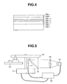
- a protective layer 10b-1, a magneto-optical recording layer 10c-1-1, 10c-1-2, 10c-1-3, a protective layer 10d-1, and a reflective layer 10e-1 are laminated and formed one upon another by a sputtering method on a resin substrate 10a-1 having an address layout in FIG. 1.
- each layer was sufficiently evacuated in advance until the reached degree of vacuum is lower than 10 -5 Pa. Then, in the atmosphere of 1 x 10 -3 Pa to 6 x 10 -3 Pa, each film was formed by a power of 2-3kW.
- a silicon nitride film of 80nm was formed by performing reactive sputtering of a silicon target in the atmosphere of argon and nitrogen.
- a film was formed to obtain 40nm film thickness by performing DC sputtering of a GdFeCoSi target in the atmosphere of argon.
- a composition of the target and a condition of film formation were adjusted in advance to achieve a transition-metal rich film having 350°C or higher Curie temperature and 10emu/cc saturation magnetization in the room temperature.
- a film was formed to obtain 40nm film thickness by performing DC sputtering of a GdFeCoSi target in the atmosphere of argon.
- a composition of the target and a condition of film formation were adjusted in advance to achieve a rare-earth-metal rich film having 200°C or higher Curie temperature and 150emu/cc saturation magnetization in the room temperature.
- a film was formed to obtain 50nm film thickness by performing DC sputtering of a TbFeCo target in the atmosphere of argon.
- a composition of the target and a condition of forming film were adjusted in advance to achieve a transition-metal rich film having 300°C or higher Curie temperature, 20KOe or greater coercivity in the room temperature, and 50emu/cc saturation magnetization in the room temperature.
- a silicon nitride film of 20nm was formed by performing reactive sputtering to a silicon target in the atmosphere of argon and nitrogen.
- the reflective film 10e-1 a film of 10nm thickness was formed by performing DC sputtering to an Al target in the atmosphere of argon.
- FIG. 5 shows an example of the device for performing bulk erase of an optical medium as constructed in FIG. 4 while heating it.
- Conventional bulk erase comprises a motor 11 for rotating a medium 10 as shown in FIG. 5, an actuator 12 for focusing a laser on a film surface of the medium 10, and a slider 13 for moving the actuator 12 in the radial direction of the medium10.
- a reflecting mirror 14 is disposed on the same side of the medium 10 as the side subjected to laser irradiation at a predetermined angle.
- Light of a strong visible-light lamp 15 is projected as parallel light to the reflecting mirror 14 via a lens 16 so as to apply light reflected by the reflecting mirror 14 to a wider area than a spot of the laser beam on the medium 10.
- 17 is a non-contact temperature sensor arranged adjacent to the medium 10 and for measuring the temperature of a substrate heated by lamp irradiation.
- control 18 is a control unit for controlling ON/OFF and the intensity of the strong visible-lamp 15 in accordance with information on the rotating conditions of the motor 11 and the substrate temperature and controlling the motor 11.
- a method of heating the medium a method which raises an ambient temperature of the medium, infrared heating by an infrared heater or the like may be adopted other than the method which uses a visible-light lamp as in the present embodiment.
- the strong visible-light lamp 15 applies light out of a lamp having a peak of light emission between ultraviolet wavelength and far infrared wavelength to an area wider than a spot of the laser beam.
- the control unit 18 controls the intensity of the strong visible-light lamp 15 in accordance with information on the substrate temperature detected by the non-contact temperature sensor 17 so as to raise the temperature of the medium 10 up to a temperature lower than a softening point of the substrate.
- the temperature of the medium 10 is, preferably, in a range of 80°C or higher to a softening point or lower for heating, for example, as a temperature which meets the condition of allowing a sufficient lowering of an increase in tracking error in the vicinity of the zone boundary as described in FIG. 3.
- control is carried out within 30°C, for example, as an in-surface temperature difference in a range that deviation or impossible achievement of a focus due to occurrence of warping is not produced.
- the medium10 Immediately after completion of application of the laser beam and heating by the strong visible-light lamp15, the medium10 is in high temperature condition and softened. Thus, if rotation of the medium10 is stopped immediately, the medium can be deformed or jump out of a chucking portion.
- control unit 18 controls the motor 11 to continue rotation of the medium 10 until the temperature of the medium reaches a temperature within a range from an ordinary temperature to 50°C after completion of application of the laser beam and heating.
- control unit 18 feedback-controls the strong visible-light lamp 15 in accordance with detected temperature information captured from the non-contact temperature sensor 17 so as to maintain the temperature of the medium 10 constant.
- a characteristic of the bulk-erased medium was examined by using the device in FIG. 5.
- Bulk erase was performed under the conditions that the linear velocity in a laser applying portion is 7.5m/s.
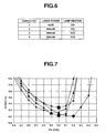
- Table in FIG. 6 four samples as shown in Table in FIG. 6 were prepared to examine a change in the recording sensitivity.
- a sample number 1 is a sample which is not subjected to bulk erase
- a sample number 2 is a sample which is subjected to normal bulk erase
- a sample number 3 is a sample which is subjected to normal bulk erase and heating
- a sample number 4 is a sample which is subjected to bulk erase with laser power reduced from 800mW to 600mW for the sample number 2 and with lamp heating.
- FIG. 7 shows the result of measurement of a value of optimum recording power for the samples.
- the horizontal axis shows a recording power
- the vertical axis shows a Jitter value of a reproducing signal, which reveals that as the recording power upon minimum Jitter value is smaller, the sensitivity is excellent
- a diamond-shaped mark shows data of the sample number 1 in FIG. 6, a square mark shows data of the sample number 2 in FIG. 6, a triangular mark shows data of the sample number 3 in FIG. 6, and a circular mark shows data of the sample number 4 in FIG. 6.
- the optimum recording power of the sample number 1 which is not subjected to bulk erase is 9.2mW, whereas a sample which is subjected to bulk erase has high sensitivity.
- the optimum recording power of the sample number 3 is 8.9mW, and the optimum recording powers of the sample numbers 2 and 4 are both 9.0mW.
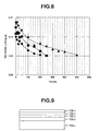
- the tracking-error increasing amounts for the sample numbers 2, 3, and 4 among the samples are shown in FIG. 8.
- the vertical axis shows a tracking-error increasing amount
- the horizontal axis shows a track number counted from the zone boundary, wherein TES NOISE is a noise derived from an address of a tracking-error signal.
- the heating means of the present invention is not limited to those with strong visible-light lamp 15 in FIG. 5, and may be constructed to raise an ambient temperature by using an air-conditioner, for example, or to perform infrared heating by an infrared heater.
- the heating means When constructing the heating means like these, it is constructed in the same way as mentioned above to raise the temperature of the medium to a temperature lower than a softening point, control an in-surface temperature difference of the medium within 30°C, continue rotation of the medium until a temperature of the medium reaches a temperature within a range from an ordinary temperature to 50°C after completion of application of the laser beam and heating, and maintain by feedback a temperature of the medium constant.
- the preheating bulk erase method of the present invention comprises carrying out magnetization or annealing of a recording film by applying a laser beam to the recording film while rotating a medium and performing a heating process for heating the medium upon irradiation of the laser beam by using, for example, the preheating bulk erase device as shown in FIG. 5.
- the heating process comprises raising a temperature of the medium lower than a softening point, controlling an in-surface temperature difference of the medium within 30°C, and maintaining by feedback a temperature of the medium constant. Moreover, it comprises continuing rotation of the medium until a temperature of the medium reaches a temperature within a range from an ordinary temperature to 50°C after completion of the heating process.
- a protective layer 10b-2, a magneto-optical recording layer 10c-2, a protective layer 10d-2, and a reflective layer 10e-2 are laminated and formed one upon another by a sputtering method on a resin substrate 10a-2 having an address layout in FIG. 1.
- a chamber for sputtering each layer was sufficiently evacuated in advance until the reached degree of vacuum is lower than 10 -5 Pa.
- a silicon nitride film of 100nm was formed by performing reactive sputtering of a silicon target in the atmosphere of argon and nitrogen.
- a film was formed to obtain 50nm film thickness by performing DC sputtering of a TbFeCo target in the atmosphere of argon.
- a composition of the target and a condition of film formation were adjusted in advance to achieve a transition-metal rich film having 300°C Curie temperature, 20Koe or higher coercivity in the room temperature, and 50emu/cc saturation magnetization in the room temperature.
- a silicon nitride film of 30nm was formed by performing reactive sputtering of a silicon target in the atmosphere of argon and nitrogen.
- a film of 50nm thickness was formed by performing DC sputtering of an AI target in the atmosphere of argon.
- a characteristic of the samples manufactured with the above film structure was examined by carrying out bulk erase by the device in FIG. 5. Bulk erase was carried out under the conditions that the linear velocity in a laser applying portion is 7.5m/s. At first, four samples shown in Table in FIG. 10 were manufactured to examine a change in recording sensitivity in the same way as in the embodiment 1.
- sample numbers, 2-2, 2-3, 2-4 have increased sensitivity as compared with a sample number 2-1 by undergoing laser irradiation and/or lamp heating.
- sample numbers 2-2, 2-4 have the same optimum sensitivity. That is, the same energy is provided to the recording films of the sample numbers 2-2, 2-4 by laser irradiation and lamp heating.
- a protective layer 10b-3, a phase-change type recording layer 10c-3, a protective layer 10d-3, and a reflective layer 10e-3 are laminated and formed one upon another by a sputtering method on a resin substrate 10a-3 having an address layout in FIG. 1.
- a chamber for sputtering each layer is sufficiently evacuated in advance until the reached degree of vacuum is lower than 10 -5 Pa.
- a ZnS-SiO 2 film of 130nm was formed by performing sputtering of a ZnS-SiO 2 target in the atmosphere of argon.
- phase-change type recording layer 10c-3 a film was formed to obtain 15nm film thickness by performing DC sputtering of a GeSbTe target in the atmosphere of argon.
- a composition of the target and a condition of film formation were adjusted in advance to have 500°C crystallizing temperature and 700°C melting point.
- a ZnS-SiO 2 film of 20nm was formed by performing sputtering of a ZnS-SiO 2 target in the atmosphere of argon.
- a film of 150nm thickness was formed by performing DC sputtering of an Al target in the atmosphere of argon.
- a characteristic of the samples manufactured with the above film structure was examined by carrying out bulk erase by the device in FIG. 5. Bulk erase was carried out under the conditions that the linear velocity in a laser applying portion is 4m/s. At first, four samples shown in Table in FIG. 12 were manufactured to examine a change in recording sensitivity in the same way as in the embodiment 1.
- sample numbers 3-2, 3-3, 3-4 have increased sensitivity as compared with a sample number 3-1 by laser irradiation and/or lamp heating. Moreover, it is seen that the sample numbers 3-2, 3-4 have the same optimum sensitivity. That is, the same energy is provided to the recording films of the sample numbers 3-2, 3-4 by laser irradiation and lamp heating.
- magnetization, annealing, and initialization can be carried out to an optical recording medium with an increase in tracking error at a band boundary being restrained. This allows fulfillment of magnetization, annealing, and initialization of the entire surface of a medium at high speed, resulting in possible shortening of process time and manufacturing of a high-quality medium having less number of replacement sectors.
- rotation of the medium can be continued until a temperature of the medium reaches a temperature within a range from an ordinary temperature to 50°C after completion of application of the laser beam and heating, preventing the medium from being deformed or jumping out of a chucking portion after completion of bulk erase.
- magnetization, annealing, and initialization to an optical recording medium can be carried out with a simple method and with an increase in tracking error at the band boundary being restrained. This allows fulfillment of magnetization, annealing, and initialization of the entire surface of the medium at high speed, resulting in possible shortening of process time and manufacturing of a high-quality medium having less number of replacement sectors.
- rotation of the medium can be continued until a temperature of the medium reaches a temperature within a range from an ordinary temperature to 50°C after completion of application of the laser beam and heating, preventing the medium from being deformed or jumping out of a chucking portion after completion of bulk erase.
- fulfillment of bulk erase restrains a change in recording sensitivity due to its use, and have no increase in tracking error in the neighborhood of the zone boundary, obtaining remarkably enhanced performance and quality.
- the present invention can be applied to an optical recording medium having outline shaped like a non-circle.
- the present invention can be also applied, as shown in FIG. 13, for example, to a card-type optical recording medium constructed by including a data record recording/reproducing area 20a in a card main body 20 of post-card size or business-card size, for example.
Applications Claiming Priority (3)
| Application Number | Priority Date | Filing Date | Title |
|---|---|---|---|
| JP2001221416 | 2001-07-23 | ||
| JP2001221416 | 2001-07-23 | ||
| PCT/JP2002/007153 WO2003010763A1 (fr) | 2001-07-23 | 2002-07-15 | Appareil et procede d'effacement par prechauffage d'un support d'enregistrement optique et support d'enregistrement optique |
Publications (1)
| Publication Number | Publication Date |
|---|---|
| EP1414030A1 true EP1414030A1 (fr) | 2004-04-28 |
Family
ID=19055089
Family Applications (1)
| Application Number | Title | Priority Date | Filing Date |
|---|---|---|---|
| EP02746044A Withdrawn EP1414030A1 (fr) | 2001-07-23 | 2002-07-15 | Appareil et procede d'effacement par prechauffage d'un support d'enregistrement optique et support d'enregistrement optique |
Country Status (6)
| Country | Link |
|---|---|
| US (2) | US7193933B2 (fr) |
| EP (1) | EP1414030A1 (fr) |
| JP (1) | JPWO2003010763A1 (fr) |
| KR (1) | KR20040022410A (fr) |
| CN (1) | CN1291404C (fr) |
| WO (1) | WO2003010763A1 (fr) |
Families Citing this family (7)
| Publication number | Priority date | Publication date | Assignee | Title |
|---|---|---|---|---|
| US7050256B1 (en) | 2004-06-29 | 2006-05-23 | The United States Of America As Represented By The Administrator Of The National Aeronautics And Space Administration | Fast erase method and apparatus for digital media |
| JP2006147099A (ja) * | 2004-11-24 | 2006-06-08 | Hitachi Global Storage Technologies Netherlands Bv | 垂直磁気記録媒体の欠陥検査方法、磁気ディスク装置、及び垂直磁気記録媒体を搭載する磁気ディスク装置における欠陥登録方法 |
| EP1818922A4 (fr) * | 2004-12-03 | 2008-07-16 | Fujitsu Ltd | Support de stockage optique, procede de fabrication de support de stockage optique et stockage optique |
| US20080008072A1 (en) * | 2004-12-27 | 2008-01-10 | Tomoaki Ito | Method for Disposing of a Data Recording Means |
| US7706102B1 (en) * | 2006-08-14 | 2010-04-27 | Lockheed Martin Corporation | Secure data storage |
| JP4627327B2 (ja) * | 2008-05-23 | 2011-02-09 | 富士通株式会社 | 異常判定装置 |
| US8014096B2 (en) * | 2009-03-13 | 2011-09-06 | Hitachi Global Storage Technologies, Netherlands B.V. | Combined bulk thermal-assister and bulk eraser |
Family Cites Families (27)
| Publication number | Priority date | Publication date | Assignee | Title |
|---|---|---|---|---|
| JPS605441A (ja) * | 1983-06-23 | 1985-01-12 | Canon Inc | 情報処理装置 |
| US4719615A (en) * | 1983-08-22 | 1988-01-12 | Optical Data, Inc. | Erasable optical data storage medium |
| DE3582778D1 (de) * | 1984-10-25 | 1991-06-13 | Matsushita Electric Ind Co Ltd | Optisches aufzeichnungsmedium. |
| JPS63171429A (ja) * | 1987-01-09 | 1988-07-15 | Fuji Electric Co Ltd | 光デイスクの記録情報の消去方法 |
| US5051970A (en) * | 1987-05-08 | 1991-09-24 | Nippon Telegraph And Telephone Corporation | Magneto-optic recording system with overwrite capability |
| US4970711A (en) * | 1988-02-05 | 1990-11-13 | Tandy Corporation | Bulk eraser for optical memory media |
| US5231614A (en) * | 1989-01-13 | 1993-07-27 | Mitsubishi Denki Kabushiki Kaisha | Magneto-optical eraser |
| US5056081A (en) * | 1990-01-02 | 1991-10-08 | Tandy Corporation | System and method for erasing light-responsive optical disks |
| US5144613A (en) * | 1990-07-26 | 1992-09-01 | Tandy Corporation | Thermal bulk erasure method for dye polymer optical media |
| JPH0487002A (ja) * | 1990-07-31 | 1992-03-19 | Toshiba Corp | 情報記録媒体処理装置 |
| JPH04147450A (ja) * | 1990-10-09 | 1992-05-20 | Fujitsu Ltd | 光磁気ディスク記録装置 |
| JPH04276315A (ja) * | 1991-03-01 | 1992-10-01 | Pioneer Electron Corp | 光学式記録媒体の初期化装置 |
| JPH07176107A (ja) * | 1993-01-12 | 1995-07-14 | Mitsubishi Electric Corp | 光磁気記録装置 |
| JP2643883B2 (ja) * | 1994-04-15 | 1997-08-20 | 日本電気株式会社 | 相変化光ディスクの初期化方法 |
| EP1669992B1 (fr) * | 1994-09-27 | 2011-03-30 | Panasonic Corporation | Procédé de production d'un support d'enregistrement d'informations optiques |
| US5688574A (en) * | 1995-03-14 | 1997-11-18 | Hitachi Maxell, Ltd. | Optical recording medium |
| JPH0935267A (ja) * | 1995-07-19 | 1997-02-07 | Sony Corp | 光学記録媒体の初期化方法とこれに用いる初期化装置 |
| JPH0991700A (ja) * | 1995-09-25 | 1997-04-04 | Sony Corp | 光学記録媒体の初期化方法とこれに用いる初期化装置 |
| JPH10241160A (ja) * | 1997-02-21 | 1998-09-11 | Nec Corp | 相変化記録媒体の初期化方法 |
| JPH11144336A (ja) * | 1997-11-07 | 1999-05-28 | Nec Corp | 記録媒体の初期化方法 |
| JP2000195112A (ja) * | 1998-12-24 | 2000-07-14 | Ricoh Co Ltd | 相変化型情報記録媒体の初期化方法 |
| US6587429B1 (en) * | 1999-11-16 | 2003-07-01 | Polaroid Corporation | System and method for initializing phase change recording media |
| US6452891B1 (en) * | 2000-01-26 | 2002-09-17 | Energy Conversion Devices, Inc. | Method for initializing a data storage device |
| JP2001236695A (ja) * | 2000-02-22 | 2001-08-31 | Ricoh Co Ltd | 光ディスク初期化装置および初期化方法 |
| JP2002203343A (ja) * | 2000-10-31 | 2002-07-19 | Matsushita Electric Ind Co Ltd | 光ディスクおよびその製造方法 |
| JP4375021B2 (ja) * | 2002-02-08 | 2009-12-02 | ソニー株式会社 | 光学記録媒体の初期化方法 |
| JP3867589B2 (ja) * | 2002-02-22 | 2007-01-10 | ソニー株式会社 | 光学記録媒体の初期化方法 |
-
2002
- 2002-07-15 EP EP02746044A patent/EP1414030A1/fr not_active Withdrawn
- 2002-07-15 US US10/381,157 patent/US7193933B2/en not_active Expired - Lifetime
- 2002-07-15 CN CNB028022564A patent/CN1291404C/zh not_active Expired - Fee Related
- 2002-07-15 JP JP2003516055A patent/JPWO2003010763A1/ja active Pending
- 2002-07-15 KR KR10-2003-7004038A patent/KR20040022410A/ko not_active Application Discontinuation
- 2002-07-15 WO PCT/JP2002/007153 patent/WO2003010763A1/fr not_active Application Discontinuation
-
2005
- 2005-10-17 US US11/252,018 patent/US7643382B2/en not_active Expired - Lifetime
Non-Patent Citations (1)
| Title |
|---|
| See references of WO03010763A1 * |
Also Published As
| Publication number | Publication date |
|---|---|
| WO2003010763A1 (fr) | 2003-02-06 |
| JPWO2003010763A1 (ja) | 2004-11-18 |
| US7643382B2 (en) | 2010-01-05 |
| US20060098536A1 (en) | 2006-05-11 |
| US20030235120A1 (en) | 2003-12-25 |
| CN1465056A (zh) | 2003-12-31 |
| CN1291404C (zh) | 2006-12-20 |
| US7193933B2 (en) | 2007-03-20 |
| KR20040022410A (ko) | 2004-03-12 |
Similar Documents
| Publication | Publication Date | Title |
|---|---|---|
| US7643382B2 (en) | Preheat bulk erasing device for phase-change type optical disk | |
| US6990053B2 (en) | Method and apparatus for initializing optical recording media | |
| JP3226418B2 (ja) | 熱的記録媒体の記録方法 | |
| JPH0452188A (ja) | 光記録媒体及びその製造方法 | |
| KR20000075827A (ko) | 상변화형 광 기록 매체 및 그 제조 방법 및 그 기록 방법 | |
| EP1752973B1 (fr) | Procédé d'enregistrement d'informations dans un support d'enregistrement optique, appareil d'enregistrement d'informations et support d'enregistrement optique | |
| EP1522996B1 (fr) | Procédé d'enregistrement d'informations d'identification, équipment correspondant et support d'enregistrement d'informations | |
| US6797130B2 (en) | Laser textured magnetic disk | |
| JPH04366424A (ja) | 光ディスク初期化方法 | |
| US6747919B2 (en) | Magneto-optical recording medium, and method and apparatus for producing the same | |
| JPH0452189A (ja) | 光記録媒体及びその製造方法 | |
| JP3076083B2 (ja) | 光ディスク初期化方法及び光ディスク記録方法 | |
| JPH07192266A (ja) | 相変化形光ディスクの初期化装置 | |
| JPH0416383A (ja) | 光記録媒体及びその製造方法 | |
| US20040265646A1 (en) | Laser textured magnetic disk | |
| JP2847977B2 (ja) | 光学記録媒体およびその製造方法 | |
| JP3015476B2 (ja) | 光磁気記録方法及び光磁気記録媒体 | |
| JP2004133989A (ja) | 光磁気記録媒体及びその製造方法 | |
| JP2637825B2 (ja) | 相変化型光ディスク | |
| JPH02199628A (ja) | 光記録媒体の重ね書き方法 | |
| JP2005285189A (ja) | 光磁気記録媒体の加熱処理方法 | |
| JPH05159299A (ja) | 光記録媒体の製造方法 | |
| JPH0414485A (ja) | 光学情報記録再生消去部材 | |
| JPH087361A (ja) | 光磁気記録媒体、その製造方法および装置 | |
| JPH10269638A (ja) | 光磁気ディスクの製造方法及び製造装置 |
Legal Events
| Date | Code | Title | Description |
|---|---|---|---|
| PUAI | Public reference made under article 153(3) epc to a published international application that has entered the european phase |
Free format text: ORIGINAL CODE: 0009012 |
|
| AK | Designated contracting states |
Kind code of ref document: A1 Designated state(s): AT BE BG CH CY CZ DE DK EE ES FI FR GB GR IE IT LI LU MC NL PT SE SK TR |
|
| 17P | Request for examination filed |
Effective date: 20030307 |
|
| STAA | Information on the status of an ep patent application or granted ep patent |
Free format text: STATUS: THE APPLICATION HAS BEEN WITHDRAWN |
|
| 18W | Application withdrawn |
Effective date: 20050722 |