EP1401052A1 - Ein Aufbau und eine Abschlusskappe zur Vermeidung von falschen Anschliessen - Google Patents
Ein Aufbau und eine Abschlusskappe zur Vermeidung von falschen Anschliessen Download PDFInfo
- Publication number
- EP1401052A1 EP1401052A1 EP03017687A EP03017687A EP1401052A1 EP 1401052 A1 EP1401052 A1 EP 1401052A1 EP 03017687 A EP03017687 A EP 03017687A EP 03017687 A EP03017687 A EP 03017687A EP 1401052 A1 EP1401052 A1 EP 1401052A1
- Authority
- EP
- European Patent Office
- Prior art keywords
- accommodating portion
- wire accommodating
- battery
- electrode
- extending
- Prior art date
- Legal status (The legal status is an assumption and is not a legal conclusion. Google has not performed a legal analysis and makes no representation as to the accuracy of the status listed.)
- Granted
Links
Images


Classifications
-
- H—ELECTRICITY
- H01—ELECTRIC ELEMENTS
- H01R—ELECTRICALLY-CONDUCTIVE CONNECTIONS; STRUCTURAL ASSOCIATIONS OF A PLURALITY OF MUTUALLY-INSULATED ELECTRICAL CONNECTING ELEMENTS; COUPLING DEVICES; CURRENT COLLECTORS
- H01R13/00—Details of coupling devices of the kinds covered by groups H01R12/70 or H01R24/00 - H01R33/00
- H01R13/64—Means for preventing incorrect coupling
- H01R13/642—Means for preventing incorrect coupling by position or shape of contact members
-
- H—ELECTRICITY
- H01—ELECTRIC ELEMENTS
- H01R—ELECTRICALLY-CONDUCTIVE CONNECTIONS; STRUCTURAL ASSOCIATIONS OF A PLURALITY OF MUTUALLY-INSULATED ELECTRICAL CONNECTING ELEMENTS; COUPLING DEVICES; CURRENT COLLECTORS
- H01R11/00—Individual connecting elements providing two or more spaced connecting locations for conductive members which are, or may be, thereby interconnected, e.g. end pieces for wires or cables supported by the wire or cable and having means for facilitating electrical connection to some other wire, terminal, or conductive member, blocks of binding posts
- H01R11/11—End pieces or tapping pieces for wires, supported by the wire and for facilitating electrical connection to some other wire, terminal or conductive member
- H01R11/28—End pieces consisting of a ferrule or sleeve
- H01R11/281—End pieces consisting of a ferrule or sleeve for connections to batteries
- H01R11/283—Bolt, screw or threaded ferrule parallel to the battery post
-
- H—ELECTRICITY
- H01—ELECTRIC ELEMENTS
- H01R—ELECTRICALLY-CONDUCTIVE CONNECTIONS; STRUCTURAL ASSOCIATIONS OF A PLURALITY OF MUTUALLY-INSULATED ELECTRICAL CONNECTING ELEMENTS; COUPLING DEVICES; CURRENT COLLECTORS
- H01R11/00—Individual connecting elements providing two or more spaced connecting locations for conductive members which are, or may be, thereby interconnected, e.g. end pieces for wires or cables supported by the wire or cable and having means for facilitating electrical connection to some other wire, terminal, or conductive member, blocks of binding posts
- H01R11/11—End pieces or tapping pieces for wires, supported by the wire and for facilitating electrical connection to some other wire, terminal or conductive member
- H01R11/12—End pieces terminating in an eye, hook, or fork
-
- H—ELECTRICITY
- H01—ELECTRIC ELEMENTS
- H01R—ELECTRICALLY-CONDUCTIVE CONNECTIONS; STRUCTURAL ASSOCIATIONS OF A PLURALITY OF MUTUALLY-INSULATED ELECTRICAL CONNECTING ELEMENTS; COUPLING DEVICES; CURRENT COLLECTORS
- H01R11/00—Individual connecting elements providing two or more spaced connecting locations for conductive members which are, or may be, thereby interconnected, e.g. end pieces for wires or cables supported by the wire or cable and having means for facilitating electrical connection to some other wire, terminal, or conductive member, blocks of binding posts
- H01R11/11—End pieces or tapping pieces for wires, supported by the wire and for facilitating electrical connection to some other wire, terminal or conductive member
- H01R11/28—End pieces consisting of a ferrule or sleeve
- H01R11/281—End pieces consisting of a ferrule or sleeve for connections to batteries
- H01R11/284—End pieces consisting of a ferrule or sleeve for connections to batteries comprising means for preventing corrosion, e.g. covers, enclosures filled with gel
-
- H—ELECTRICITY
- H01—ELECTRIC ELEMENTS
- H01R—ELECTRICALLY-CONDUCTIVE CONNECTIONS; STRUCTURAL ASSOCIATIONS OF A PLURALITY OF MUTUALLY-INSULATED ELECTRICAL CONNECTING ELEMENTS; COUPLING DEVICES; CURRENT COLLECTORS
- H01R13/00—Details of coupling devices of the kinds covered by groups H01R12/70 or H01R24/00 - H01R33/00
- H01R13/46—Bases; Cases
- H01R13/50—Bases; Cases formed as an integral body
- H01R13/501—Bases; Cases formed as an integral body comprising an integral hinge or a frangible part
-
- H—ELECTRICITY
- H01—ELECTRIC ELEMENTS
- H01R—ELECTRICALLY-CONDUCTIVE CONNECTIONS; STRUCTURAL ASSOCIATIONS OF A PLURALITY OF MUTUALLY-INSULATED ELECTRICAL CONNECTING ELEMENTS; COUPLING DEVICES; CURRENT COLLECTORS
- H01R4/00—Electrically-conductive connections between two or more conductive members in direct contact, i.e. touching one another; Means for effecting or maintaining such contact; Electrically-conductive connections having two or more spaced connecting locations for conductors and using contact members penetrating insulation
- H01R4/28—Clamped connections, spring connections
- H01R4/30—Clamped connections, spring connections utilising a screw or nut clamping member
- H01R4/305—Clamped connections, spring connections utilising a screw or nut clamping member having means for facilitating engagement of conductive member or for holding it in position
Definitions
- the present invention relates to a construction and to a terminal cap for preventing erroneous connection of two batteries of different type by a connection means such as a booster cable.
- a conventional low-voltage battery and a high-voltage battery may be connected by a booster cable when a battery dies.
- an object of the present invention is to provide a construction and a terminal cap for preventing batteries having different specifications from being erroneously connected e.g. by a booster cable.
- a construction for preventing erroneous connection of a high-voltage battery and a low-voltage battery mounted in automotive vehicles by a booster cable wherein a protecting portion for making connection with an electrode portion impossible by interfering a clip connected with an end of the booster cable projects in a portion of either one of the batteries around an electrode.
- a terminal cap is mounted or mountable to substantially cover a battery terminal connected or connectable with the electrode, and the protecting portion is integrally or unitarily formed in or with the terminal cap.
- the protecting portion is provided utilizing the existing terminal cap for covering the battery terminal and the electrode, it is not necessary to add a special construction to prevent erroneous connection.
- a first accommodating portion for at least partly accommodating a connecting portion of the battery terminal to be connected with the electrode is preferably formed at the leading end of the terminal cap and the protecting portion is formed such that an opening edge of the first accommodating portion is located higher or is more projectingly or projecting by a greater distance than the upper or projecting end of the electrode when the battery terminal substantially covered by the terminal cap is connected with the electrode.
- the opening edge of the first accommodating portion of the terminal cap is located higher than the upper end of the electrode.
- the clip of the booster cable trying to be connected with the electrode is interfered by the upper or projecting edge of the first accommodating portion, thereby making connection with the electrode impossible.
- a plurality of battery terminals are connected or connectable with the electrode while being placed substantially one over another, the terminal cap is mounted or mountable to at least partly cover the uppermost battery terminal, and the opening edge of the first accommodating portion of the terminal cap is preferably located higher or more projecting than the upper or projecting end of the electrode.
- connection means preferably of the booster cable can be securely avoided if the terminal cap is mounted to at least partly cover the uppermost battery terminal and the opening edge of the first accommodating portion thereof is set above the electrode.
- a terminal cap in particular as a preferred embodiment of the construction according to the invention or an embodiment thereof, for preventing erroneous connection of two batteries of different type, preferably of a high-voltage battery and a low-voltage battery mounted in automotive vehicles by a connection means such as a booster cable, comprising at least one integrally or unitarily formed protecting portion being mountable to substantially cover a battery terminal connectable with an electrode portion of one of the batteries so that a connection with the electrode portion is made impossible by interfering a clip connected with an end of the connection means, preferably of the booster cable.
- a connection means such as a booster cable
- a first accommodating portion for at least partly accommodating a connecting portion of the battery terminal to be connected with the electrode is formed at the leading end of the terminal cap.
- the protecting portion is formed such that an opening edge of the first accommodating portion is higher or more projectingly provided or projecting by a greater distance than the upper end of the electrode when the battery terminal substantially covered by the terminal cap is connected with the electrode.
- FIGS. 1 to 5 show a first preferred embodiment of the present invention.
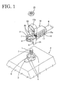
- B in FIG. 1 is a battery of a predetermined type, e.g. a 36V-battery to be mounted in an automotive vehicle, and a threaded shaft 1 as an electrode stands e.g. on the upper or first surface of the battery B.
- a (+)-electrode is shown in FIG. 1.
- a first nut 2 is or can be screwed down on the threaded shaft 1, and a washer 3 and a rotation preventing member 4 are fastened between the first nut 2 and the upper surface of the battery B.
- the rotation preventing member 4 is formed at its periphery with rotation one or more preventing projections 5 which preferably are circumferentially spaced apart e.g. at an interval of about 90°.
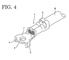
- the battery terminal T is or can be connected with a core or a conductor of a wire "w" exposed by stripping a leading end of a coating off.
- the battery terminal T is formed e.g. by stamping a conductive metallic plate out and is formed at its rear part with a core connecting portion and a barrel portion 6 connectable with the coating of the wire "w" preferably by crimping.
- a connecting portion 7 for connection with the threaded shaft 1 is formed at a front part of the battery terminal T, and a through hole 8 through which the threaded shaft 1 is insertable is formed in the center of the connecting portion 7.
- a pair of downward extending locking projections 9 are formed at the outer periphery of the connecting portion 7 e.g. by bending.
- a terminal cap 10 made e.g. of a synthetic resin is mounted or mountable preferably only on the battery terminal T to be connected with the (+)-electrode.
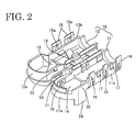
- the terminal cap 10 is comprised of a fixed portion 11 for at least partly accommodating the battery terminal T and a covering portion 12 continuously (unitarily or integrally) provided with the fixed portion 11 via a hinge so as to open and close.
- the fixed portion 11 is comprised of a first accommodating portion 11a for at least partly accommodating the connecting portion 7 of the battery terminal T and a second accommodating portion 11b for at least partly accommodating a section of the wire "w".
- the covering portion 12 is comprised of a first lid 12a substantially corresponding to the first accommodating portion 11 a and a second lid 12b substantially corresponding to the second accommodating portion 11 b.
- the second lid 12b is pivotal to open and close about second hinges 14 provided preferably on one longer side of the second accommodating portion 11 b, and one or more locking arms 15 project at a specified (predeterminable or predeterminable) distance from an edge of the second lid 12b opposite from the second hinges 14.
- Each locking arm 15 is formed with a locking hole or recess 15a.
- preferably three guide pieces 16 stand from the other longer side of the second accommodating portion 11b as shown, and preferably two locking projections 17 project substantially between or adjacent to the guide pieces 16.
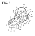
- the first accommodating portion 11a is formed to preferably have a substantially semicircular outer configuration and is formed inside with a connection opening 18 so as to cause the locking projections 9 of the battery terminal T to project down between the rotation preventing projections 5 of the rotation preventing member 4 when the connecting portion 7 of the battery terminal T is at least partly fitted into the first accommodating portion 11a. In this way, rotation or relative movement of the terminal cap 10 and the battery terminal T with respect to the electrode can be substantially prevented. Further, a substantially arcuate guiding projection 19 projects at the front end of the upper edge of the first accommodating portion 11a to guide the closing movement of the first lid 12a.
- Upper or first protection walls 20 stand at or project from the substantially opposite sides of the first accommodating portion 11a in such a manner as to substantially face each other, and a locking recess 21 is formed in the inner surface of each upper protection wall 20.
- the first lid 12a is pivotal to substantially open and close about a first hinge 13 provided at the front edge of the second lid 12b.
- the inner surface of the first lid 12a is or can be guided by the guiding projection 19 while the first lid 12a is being closed, and a pair of locking projections 22 provided on the outer surface of the first lid 12a are engaged with the corresponding locking recesses 21 to hold the first lid 12a closed.
- Lower or second protection walls 24 extend downward from the first accommodating portion 11a.
- the lower protection walls 24 have a width smaller than the upper protection walls 20 and preferably are substantially in flush with the outer surfaces of the upper protection walls 20.
- the lower protection walls 24 extend downward such that their bottom ends are located lower than the bottom end positions of the locking projections 9 when the battery terminal T is accommodated in the terminal cap 10 and substantially abut on the upper surface of the battery B when the battery terminal T is connected with the threaded shaft 1 together with the terminal cap 10.
- the upper or projecting end positions of the upper protection walls 20 are located higher or more projecting than the upper or projecting end of the threaded shaft 1.
- the protection walls 20 have a projecting length which is greater than that of the threaded shaft 1 so that the threaded shaft 1 cannot be reached by a clip or clamp C of the booster cable as a preferred connection means. Due to this and a specified spacing of the upper protection walls 20, a clip or clamp C mounted at the leading end of a booster cable is interfered by the upper protection walls 20 and cannot clamp the threaded shaft 1 or a second nut 25 for fastening the battery terminal T.
- the terminal cap 10 is first mounted on the battery terminal T to be connected with the (+)-electrode. In this case, the terminal cap 10 is left fully open as shown in FIG. 2.
- the second lid 12b is first closed to engage the locking projections 17 with the locking holes 15a of the locking arms 15 while being guided by the respective guide pieces 16. As a result, the second lid 12b is held substantially closed.
- the threaded shaft 1 is connectable with the terminal T by being preferably inserted through the through hole 8 of the battery terminal T, and the locking projections 9 of the battery terminal T are caused to enter substantially between the rotation preventing projections 5 of the rotation preventing member 4. If the second nut 25 is then screwed down on the threaded shaft 1, the battery terminal T is connected with the threaded shaft 1. Finally, the first lid 12a is closed about the first hinge 13 to engage the corresponding locking projections 22 and locking recesses 21, thereby holding the first lid 12a substantially closed. In this way, connection of the battery terminal T is completed.
- the locking projections 22 and the locking recesses 21 are forcibly disengaged from each other and the first lid 12a is left open.
- the clip C of the booster cable is normally gripped to clamp the threaded shaft 1 or the second nut 25 while widening a spacing of the leading ends of the clip or clamp C.
- the upper ends of the upper protection walls 20 of the terminal cap 10 are higher than the upper end of the threaded shaft 1 and the spacing thereof is set such that the clip C cannot enter the first accommodating portion 11a by being interfered by the upper protection walls 20 while being left open as shown in FIG. 5, the clip C cannot clamp either the threaded shaft 1 or the second nut 25. Therefore, erroneous connection of batteries B having different specifications can be avoided.
- a terminal cap 10 is or can be mounted to cover a battery terminal T to be connected with one of electrodes of a 32V-battery.
- one or more protection walls 20 stand on edges of a first accommodating portion 11a for accommodating a connecting portion 7 of the battery terminal T.
- the protection walls 20 are formed to be higher or more projecting than a threaded shaft 1 of the electrode.
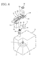
- FIGS. 6 and 7 show a second preferred embodiment of the present invention.
- battery terminals T1, T2 are connected with an electrode (e.g. a (+)-electrode) of a battery B while being placed one over the other.
- an electrode e.g. a (+)-electrode
- the (+)-electrode of the battery B is provided in a recess 26 formed therearound, and the electrode is constructed by projecting a threaded shaft 1 on a washer 27.
- the below-located one T1 of the two battery terminals T1, T2 is used as it is without being covered by a terminal cap 10.
- a connecting portion 7a is bent with respect to a barrel portion 6a, and a round hole 28 through which the threaded shaft 1 is insertable is formed in the center of the connecting portion 7a.
- the opposite sides of the connecting portion 7a are bent downward to form a pair of holding pieces 29 for preventing rotation of the battery terminals T1, T2 by holding the washer 27 therebetween.
- the terminal cap 10 is mounted on the above-located one T2 of the two battery terminals T1, T2.
- a basic construction of the terminal cap 10 is as described in the first embodiment except that a rear part of a second accommodating portion 11b is bent downward to form a bent portion 12c extending along one side surface of the battery B, and this bent portion 12c is closed on three sides and open on one side substantially facing the battery B so as to substantially cover the barrel portion 6a sideways.
- upper protection walls 20 of the terminal cap 10 are so dimensioned that the threaded shaft 1 does not project therefrom with the battery terminals T1, T2 connected with the threaded shaft 1 and are so spaced apart that a clip C of a booster cable cannot be connected with either the threaded shaft 1 or the second nut 25 while the clip C is being left open.
Applications Claiming Priority (3)
| Application Number | Priority Date | Filing Date | Title |
|---|---|---|---|
| JP2000064944 | 2000-03-09 | ||
| JP2000064944A JP2001257016A (ja) | 2000-03-09 | 2000-03-09 | ブースタケーブルの誤接続防止構造 |
| EP01105366A EP1133007A1 (de) | 2000-03-09 | 2001-03-08 | Ein Aufbau und eine Abschlusskappe zur Vermeidung von falschem Anschliessen |
Related Parent Applications (1)
| Application Number | Title | Priority Date | Filing Date |
|---|---|---|---|
| EP01105366A Division EP1133007A1 (de) | 2000-03-09 | 2001-03-08 | Ein Aufbau und eine Abschlusskappe zur Vermeidung von falschem Anschliessen |
Publications (2)
| Publication Number | Publication Date |
|---|---|
| EP1401052A1 true EP1401052A1 (de) | 2004-03-24 |
| EP1401052B1 EP1401052B1 (de) | 2007-04-25 |
Family
ID=18584558
Family Applications (2)
| Application Number | Title | Priority Date | Filing Date |
|---|---|---|---|
| EP01105366A Withdrawn EP1133007A1 (de) | 2000-03-09 | 2001-03-08 | Ein Aufbau und eine Abschlusskappe zur Vermeidung von falschem Anschliessen |
| EP03017687A Expired - Lifetime EP1401052B1 (de) | 2000-03-09 | 2001-03-08 | Ein Aufbau und eine Abschlusskappe zur Vermeidung von falschen Anschliessen |
Family Applications Before (1)
| Application Number | Title | Priority Date | Filing Date |
|---|---|---|---|
| EP01105366A Withdrawn EP1133007A1 (de) | 2000-03-09 | 2001-03-08 | Ein Aufbau und eine Abschlusskappe zur Vermeidung von falschem Anschliessen |
Country Status (4)
| Country | Link |
|---|---|
| US (1) | US6533619B2 (de) |
| EP (2) | EP1133007A1 (de) |
| JP (1) | JP2001257016A (de) |
| DE (1) | DE60128153T2 (de) |
Cited By (3)
| Publication number | Priority date | Publication date | Assignee | Title |
|---|---|---|---|---|
| WO2012020000A1 (en) * | 2010-08-13 | 2012-02-16 | Tyco Electronics Amp Gmbh | Electrical plug connector |
| CN102782946A (zh) * | 2010-02-15 | 2012-11-14 | 矢崎总业株式会社 | 用于防止直接安装在蓄电池上熔断器的倾斜紧固的保护帽 |
| DE102019210427A1 (de) * | 2019-07-15 | 2021-01-21 | Volkswagen Aktiengesellschaft | Verfahren zur Herstellung eines elektrisch leitenden Verbindungselements sowie Verbindungsanordnung mit diesem Verbindungselement |
Families Citing this family (43)
| Publication number | Priority date | Publication date | Assignee | Title |
|---|---|---|---|---|
| JP2003317823A (ja) * | 2002-04-25 | 2003-11-07 | Yazaki Corp | 端子保護キャップ |
| EP1369957A1 (de) * | 2002-05-28 | 2003-12-10 | Tyco Electronics AMP GmbH | Steckverbinder zum Kontaktieren eines Pols einer Batterie |
| US7490033B2 (en) * | 2005-01-13 | 2009-02-10 | International Business Machines Corporation | System for compiling word usage frequencies |
| KR100846074B1 (ko) * | 2005-05-09 | 2008-07-14 | 주식회사 엘지화학 | 파우치형 전지의 입체형 전극단자 |
| US7361841B1 (en) * | 2005-06-23 | 2008-04-22 | Yazaki North America, Inc. | Terminal cover with hinge |
| JP4920358B2 (ja) * | 2006-09-19 | 2012-04-18 | 矢崎総業株式会社 | 端子カバー |
| US7300316B1 (en) * | 2006-12-06 | 2007-11-27 | Cyber Power System Inc. | Electrical connecting assembly |
| JP5050949B2 (ja) * | 2008-03-21 | 2012-10-17 | 住友電装株式会社 | ターミナルカバー |
| JP5075725B2 (ja) * | 2008-04-23 | 2012-11-21 | 矢崎総業株式会社 | ロック構造及びターミナルキャップのカバーロック構造 |
| JP5336768B2 (ja) * | 2008-05-19 | 2013-11-06 | タイコエレクトロニクスジャパン合同会社 | 端子カバー |
| JP5360582B2 (ja) * | 2009-10-28 | 2013-12-04 | 住友電装株式会社 | 電気接続箱 |
| DE102010036397A1 (de) | 2010-07-14 | 2012-01-19 | Dr. Ing. H.C. F. Porsche Aktiengesellschaft | Automatische Erkennung einer Zellchemie bzw. eines Batterietyps einer Batterie |
| US8313343B2 (en) | 2010-08-31 | 2012-11-20 | Hamilton Sundstrand Corporation | Terminal block cover with nut retention feature |
| ITBO20110466A1 (it) * | 2011-07-29 | 2013-01-30 | Magneti Marelli Spa | Sistema di connessione per stabilire un collegamento elettrico tra un dispositivo elettrico per autotrazione ed almeno una coppia di cavi |
| HK1158011A2 (en) * | 2012-02-03 | 2012-06-22 | Gilkron Ltd | An online procurement system for the provision of intellectually oriented services |
| DE102012108197A1 (de) | 2012-09-04 | 2014-03-06 | Linde Material Handling Gmbh | Batteriepolabdeckung einer Starterbatterie eines Fahrzeugs |
| JP2014189188A (ja) * | 2013-03-27 | 2014-10-06 | Showa Corp | ステアリング装置 |
| JP6292524B2 (ja) * | 2013-04-04 | 2018-03-14 | パナソニックIpマネジメント株式会社 | 電子機器、アタッチメント、及び接続ケーブル |
| JP6040881B2 (ja) * | 2013-07-12 | 2016-12-07 | 住友電装株式会社 | カバー付き端子 |
| JP6265647B2 (ja) * | 2013-08-06 | 2018-01-24 | 矢崎総業株式会社 | ターミナル固定補助部材 |
| EP2840657B1 (de) * | 2013-08-19 | 2019-11-06 | Tyco Electronics UK Ltd. | Befestigungskomponente, Anschlussklemmenschuh, Kit und elektrische Verbindungsanordnung für eine drehfeste elektrische Verbindung eines Kabels |
| JP2015069772A (ja) * | 2013-09-27 | 2015-04-13 | オムロン株式会社 | リード線の接続構造およびこれを用いた電子機器 |
| JP6279307B2 (ja) | 2013-12-19 | 2018-02-14 | 矢崎総業株式会社 | バッテリー端子ストッパ、及び、バッテリー端子ユニット |
| US9744703B2 (en) | 2014-03-05 | 2017-08-29 | Standard Cable USA, Inc. | Method of manufacture insulating electrical plugs |
| US9627793B2 (en) | 2014-03-05 | 2017-04-18 | Standard Cable USA, Inc. | Insulating electrical plugs and method of manufacture |
| US9142911B1 (en) * | 2014-03-05 | 2015-09-22 | Standard Cable USA, Inc. | Insulating electrical plugs and method of manufacture |
| EP3079205B1 (de) * | 2015-04-08 | 2019-12-18 | Delta Electronics (Thailand) Public Co., Ltd. | Befestigungsschelle |
| US9837735B2 (en) * | 2016-02-11 | 2017-12-05 | Sumitomo Wiring Systems, Ltd. | Cover with integrated hinge and locking mechanism for vehicle electrical system component |
| WO2017201033A1 (en) * | 2016-05-16 | 2017-11-23 | Johnson Controls Technology Company | Push fit main battery terminal connectors with geometrical lockout features |
| JP6744578B2 (ja) * | 2017-01-26 | 2020-08-19 | 住友電装株式会社 | カバー部材及び機器用コネクタ |
| KR200486965Y1 (ko) * | 2017-05-08 | 2018-07-18 | 한국단자공업 주식회사 | 단자 캡 |
| US10950955B2 (en) * | 2017-11-08 | 2021-03-16 | Hubbell Incorporated | Insulation piercing connector |
| JP2019133850A (ja) * | 2018-01-31 | 2019-08-08 | トヨタ自動車株式会社 | アース端子の組み付け構造 |
| IT201800003963A1 (it) * | 2018-03-26 | 2019-09-26 | Mta Spa | Morsetto per un terminale maschio di una sorgente di energia elettrica. |
| US11170916B2 (en) | 2018-11-05 | 2021-11-09 | Lear Corporation | Cover |
| JP7172719B2 (ja) * | 2019-02-25 | 2022-11-16 | 株式会社デンソー | 端子カバー |
| FR3105618B1 (fr) * | 2019-12-19 | 2022-06-17 | Valeo Siemens eAutomotive France | Procédé de fixation d’un connecteur électrique prévu à une extrémité d’un câble électrique à une borne électrique, support intermédiaire correspondant et dispositif comportant un tel support intermédiaire |
| DE102020002701B4 (de) * | 2020-05-06 | 2023-10-05 | Auto-Kabel Management Gmbh | Dichtungsgehäuse |
| JP7273019B2 (ja) * | 2020-11-30 | 2023-05-12 | 矢崎総業株式会社 | 端子、及び、端子の固定構造 |
| DE102021107713A1 (de) * | 2021-03-26 | 2022-09-29 | Te Connectivity Germany Gmbh | Elektrisch isolierende berührungsschutzvorrichtung und verbindungsanordnung mit einer solchen berührungsschutzvorrichtung |
| FR3121796B1 (fr) * | 2021-04-12 | 2023-02-24 | Psa Automobiles Sa | Vehicule automobile comportant une batterie electrique et un support metallique au-dessus |
| WO2022246289A2 (en) * | 2021-05-21 | 2022-11-24 | Cps Technology Holdings Llc | Battery connector and battery cover |
| DE102021117220A1 (de) * | 2021-07-05 | 2023-01-05 | Harting Electric Stiftung & Co. Kg | Modulanschlusssystem für Energiespeichersysteme |
Citations (6)
| Publication number | Priority date | Publication date | Assignee | Title |
|---|---|---|---|---|
| DE8520278U1 (de) * | 1985-07-13 | 1985-09-19 | Varta Batterie Ag, 3000 Hannover | Kabelverbinder zum Anschluß an die Endpole elektrischer Akkumulatoren |
| DE3736414C1 (en) * | 1987-10-28 | 1988-11-10 | Rose Walter Gmbh & Co Kg | Device for protecting the end terminals of electrical accumulators (rechargeable batteries) |
| FR2688945A1 (fr) * | 1992-03-23 | 1993-09-24 | Amp France | Connecteur pour borne de batterie a connexion rapide. |
| EP0603872A2 (de) * | 1992-12-25 | 1994-06-29 | Sumitomo Wiring Systems, Ltd. | Abschlusskappe und Kappenbefestigungsanordnung |
| JPH10220424A (ja) * | 1997-02-07 | 1998-08-21 | Yazaki Corp | 回動部材のロック機構 |
| JPH10338085A (ja) * | 1997-06-09 | 1998-12-22 | Yazaki Corp | ヒュージブルリンクボックス |
Family Cites Families (11)
| Publication number | Priority date | Publication date | Assignee | Title |
|---|---|---|---|---|
| JPS62129775U (de) * | 1986-02-10 | 1987-08-17 | ||
| JPH0334058Y2 (de) * | 1987-08-11 | 1991-07-18 | ||
| US5295860A (en) * | 1992-10-15 | 1994-03-22 | Ford Motor Company | Integral battery cable solenoid connector |
| JP2815081B2 (ja) * | 1993-02-18 | 1998-10-27 | 矢崎総業株式会社 | バッテリ間接続用コネクタ装置 |
| US5439759A (en) * | 1994-11-04 | 1995-08-08 | Yazaki Corporation | Cover for battery cable terminal |
| US5791936A (en) * | 1996-06-20 | 1998-08-11 | Yazaki Corporation | Protective cover for ground junction connector |
| US5977485A (en) * | 1996-09-25 | 1999-11-02 | Sumitomo Wiring Systems, Ltd. | Battery connector cover |
| JP3373400B2 (ja) * | 1997-09-04 | 2003-02-04 | 株式会社オートネットワーク技術研究所 | バッテリポストと信号用電線の接続構造 |
| JPH1186840A (ja) * | 1997-09-08 | 1999-03-30 | Harness Sogo Gijutsu Kenkyusho:Kk | バッテリ用接続具 |
| JP3373401B2 (ja) * | 1997-09-08 | 2003-02-04 | 株式会社オートネットワーク技術研究所 | バッテリポストと信号用電線の接続構造 |
| US6203383B1 (en) * | 2000-01-04 | 2001-03-20 | Scosche Industries, Inc. | Lever action battery terminal apparatus |
-
2000
- 2000-03-09 JP JP2000064944A patent/JP2001257016A/ja active Pending
-
2001
- 2001-03-08 EP EP01105366A patent/EP1133007A1/de not_active Withdrawn
- 2001-03-08 DE DE60128153T patent/DE60128153T2/de not_active Expired - Lifetime
- 2001-03-08 EP EP03017687A patent/EP1401052B1/de not_active Expired - Lifetime
- 2001-03-09 US US09/803,069 patent/US6533619B2/en not_active Expired - Fee Related
Patent Citations (6)
| Publication number | Priority date | Publication date | Assignee | Title |
|---|---|---|---|---|
| DE8520278U1 (de) * | 1985-07-13 | 1985-09-19 | Varta Batterie Ag, 3000 Hannover | Kabelverbinder zum Anschluß an die Endpole elektrischer Akkumulatoren |
| DE3736414C1 (en) * | 1987-10-28 | 1988-11-10 | Rose Walter Gmbh & Co Kg | Device for protecting the end terminals of electrical accumulators (rechargeable batteries) |
| FR2688945A1 (fr) * | 1992-03-23 | 1993-09-24 | Amp France | Connecteur pour borne de batterie a connexion rapide. |
| EP0603872A2 (de) * | 1992-12-25 | 1994-06-29 | Sumitomo Wiring Systems, Ltd. | Abschlusskappe und Kappenbefestigungsanordnung |
| JPH10220424A (ja) * | 1997-02-07 | 1998-08-21 | Yazaki Corp | 回動部材のロック機構 |
| JPH10338085A (ja) * | 1997-06-09 | 1998-12-22 | Yazaki Corp | ヒュージブルリンクボックス |
Non-Patent Citations (2)
| Title |
|---|
| PATENT ABSTRACTS OF JAPAN vol. 1998, no. 13 30 November 1998 (1998-11-30) * |
| PATENT ABSTRACTS OF JAPAN vol. 1999, no. 03 31 March 1999 (1999-03-31) * |
Cited By (5)
| Publication number | Priority date | Publication date | Assignee | Title |
|---|---|---|---|---|
| CN102782946A (zh) * | 2010-02-15 | 2012-11-14 | 矢崎总业株式会社 | 用于防止直接安装在蓄电池上熔断器的倾斜紧固的保护帽 |
| CN102782946B (zh) * | 2010-02-15 | 2015-12-09 | 矢崎总业株式会社 | 用于防止直接安装在蓄电池上熔断器的倾斜紧固的保护帽 |
| WO2012020000A1 (en) * | 2010-08-13 | 2012-02-16 | Tyco Electronics Amp Gmbh | Electrical plug connector |
| US9130295B2 (en) | 2010-08-13 | 2015-09-08 | Tyco Electronics Amp Gmbh | Electrical plug connector |
| DE102019210427A1 (de) * | 2019-07-15 | 2021-01-21 | Volkswagen Aktiengesellschaft | Verfahren zur Herstellung eines elektrisch leitenden Verbindungselements sowie Verbindungsanordnung mit diesem Verbindungselement |
Also Published As
| Publication number | Publication date |
|---|---|
| DE60128153D1 (de) | 2007-06-06 |
| JP2001257016A (ja) | 2001-09-21 |
| US20010024909A1 (en) | 2001-09-27 |
| EP1133007A1 (de) | 2001-09-12 |
| DE60128153T2 (de) | 2008-01-03 |
| US6533619B2 (en) | 2003-03-18 |
| EP1401052B1 (de) | 2007-04-25 |
Similar Documents
| Publication | Publication Date | Title |
|---|---|---|
| EP1401052A1 (de) | Ein Aufbau und eine Abschlusskappe zur Vermeidung von falschen Anschliessen | |
| EP1050932B1 (de) | Eine abgeschirmte Anschlussklemme und ein Verfahren für die Verbindung einer abgeschirmten Anschlussklemme | |
| US7488195B2 (en) | Transparent insulating enclosure | |
| US6828058B2 (en) | Battery connecting portion-protecting cover | |
| EP1005106B1 (de) | Anschluss und Anpressverfahren | |
| EP2156519B1 (de) | Steckverbindergehäuse mit einer fixierung für ein elektrisches kontaktlelement und eine elektrische leitung | |
| EP1156552B1 (de) | Anordnung zum Vorbeugen von falsch Anschliessen von Batterieklemmen, Batterie und Kontaktklemmen | |
| EP2905845B1 (de) | Ladestecker | |
| CN109314375A (zh) | 电气连接箱 | |
| US10348019B1 (en) | Connector assembly with locking feature | |
| EP2905846B1 (de) | Klemmenabstandhalter | |
| JP3606365B2 (ja) | バッテリ端子の保護カバー | |
| EP0963009A1 (de) | Eine Vorrichtung zur Verhinderung einer fehlerhaften Zusammensetzung eines Verbindergehäuses mit einem Deckel und einen Verbinder mit einer solchen Vorrichtung | |
| JP2001128337A (ja) | 電線プロテクタの電線導出構造 | |
| EP3985803B1 (de) | Verbinder und verbinder mit elektrischen drähten mit dem verbinder | |
| JP2002025685A (ja) | 保護カバー | |
| GB2057792A (en) | Non-rewirable electric plug | |
| JP2593241Y2 (ja) | ジョイントコネクタ | |
| JP3196682B2 (ja) | 電気接続箱 | |
| JP2002369338A (ja) | ヒューズボックス | |
| JP6770695B2 (ja) | 電気接続箱 | |
| JPH0877912A (ja) | ヒューズホルダ | |
| JPH0577871U (ja) | 防水型電気コネクタ | |
| GB2060283A (en) | Electrical plugs | |
| JP3463485B2 (ja) | コンセント |
Legal Events
| Date | Code | Title | Description |
|---|---|---|---|
| PUAI | Public reference made under article 153(3) epc to a published international application that has entered the european phase |
Free format text: ORIGINAL CODE: 0009012 |
|
| AC | Divisional application: reference to earlier application |
Ref document number: 1133007 Country of ref document: EP Kind code of ref document: P |
|
| AK | Designated contracting states |
Kind code of ref document: A1 Designated state(s): DE FR GB IT |
|
| 17P | Request for examination filed |
Effective date: 20040429 |
|
| 17Q | First examination report despatched |
Effective date: 20040709 |
|
| AKX | Designation fees paid |
Designated state(s): DE FR GB IT |
|
| 17Q | First examination report despatched |
Effective date: 20040709 |
|
| GRAP | Despatch of communication of intention to grant a patent |
Free format text: ORIGINAL CODE: EPIDOSNIGR1 |
|
| GRAS | Grant fee paid |
Free format text: ORIGINAL CODE: EPIDOSNIGR3 |
|
| GRAA | (expected) grant |
Free format text: ORIGINAL CODE: 0009210 |
|
| AC | Divisional application: reference to earlier application |
Ref document number: 1133007 Country of ref document: EP Kind code of ref document: P |
|
| AK | Designated contracting states |
Kind code of ref document: B1 Designated state(s): DE FR GB IT |
|
| REG | Reference to a national code |
Ref country code: GB Ref legal event code: FG4D |
|
| REF | Corresponds to: |
Ref document number: 60128153 Country of ref document: DE Date of ref document: 20070606 Kind code of ref document: P |
|
| ET | Fr: translation filed | ||
| PLBE | No opposition filed within time limit |
Free format text: ORIGINAL CODE: 0009261 |
|
| STAA | Information on the status of an ep patent application or granted ep patent |
Free format text: STATUS: NO OPPOSITION FILED WITHIN TIME LIMIT |
|
| 26N | No opposition filed |
Effective date: 20080128 |
|
| PGFP | Annual fee paid to national office [announced via postgrant information from national office to epo] |
Ref country code: GB Payment date: 20080305 Year of fee payment: 8 Ref country code: IT Payment date: 20080322 Year of fee payment: 8 |
|
| PGFP | Annual fee paid to national office [announced via postgrant information from national office to epo] |
Ref country code: FR Payment date: 20080311 Year of fee payment: 8 |
|
| GBPC | Gb: european patent ceased through non-payment of renewal fee |
Effective date: 20090308 |
|
| REG | Reference to a national code |
Ref country code: FR Ref legal event code: ST Effective date: 20091130 |
|
| PG25 | Lapsed in a contracting state [announced via postgrant information from national office to epo] |
Ref country code: GB Free format text: LAPSE BECAUSE OF NON-PAYMENT OF DUE FEES Effective date: 20090308 Ref country code: FR Free format text: LAPSE BECAUSE OF NON-PAYMENT OF DUE FEES Effective date: 20091123 |
|
| PGFP | Annual fee paid to national office [announced via postgrant information from national office to epo] |
Ref country code: DE Payment date: 20100318 Year of fee payment: 10 |
|
| PG25 | Lapsed in a contracting state [announced via postgrant information from national office to epo] |
Ref country code: IT Free format text: LAPSE BECAUSE OF NON-PAYMENT OF DUE FEES Effective date: 20090308 |
|
| PG25 | Lapsed in a contracting state [announced via postgrant information from national office to epo] |
Ref country code: DE Free format text: LAPSE BECAUSE OF NON-PAYMENT OF DUE FEES Effective date: 20111001 |
|
| REG | Reference to a national code |
Ref country code: DE Ref legal event code: R119 Ref document number: 60128153 Country of ref document: DE Effective date: 20111001 |