EP1393396B1 - Methods and apparatuses for a pressure driven fuel cell system - Google Patents
Methods and apparatuses for a pressure driven fuel cell system Download PDFInfo
- Publication number
- EP1393396B1 EP1393396B1 EP02736784A EP02736784A EP1393396B1 EP 1393396 B1 EP1393396 B1 EP 1393396B1 EP 02736784 A EP02736784 A EP 02736784A EP 02736784 A EP02736784 A EP 02736784A EP 1393396 B1 EP1393396 B1 EP 1393396B1
- Authority
- EP
- European Patent Office
- Prior art keywords
- chamber
- fuel
- fuel cell
- anode
- valve
- Prior art date
- Legal status (The legal status is an assumption and is not a legal conclusion. Google has not performed a legal analysis and makes no representation as to the accuracy of the status listed.)
- Expired - Lifetime
Links
- 239000000446 fuel Substances 0.000 title claims abstract description 261
- 238000000034 method Methods 0.000 title claims description 44
- 239000000203 mixture Substances 0.000 claims abstract description 71
- 239000007788 liquid Substances 0.000 claims abstract description 59
- 238000004891 communication Methods 0.000 claims abstract description 18
- 239000012528 membrane Substances 0.000 claims abstract description 18
- 239000003054 catalyst Substances 0.000 claims abstract description 11
- XLYOFNOQVPJJNP-UHFFFAOYSA-N water Substances O XLYOFNOQVPJJNP-UHFFFAOYSA-N 0.000 claims description 109
- OKKJLVBELUTLKV-UHFFFAOYSA-N Methanol Chemical compound OC OKKJLVBELUTLKV-UHFFFAOYSA-N 0.000 claims description 48
- 230000003647 oxidation Effects 0.000 claims description 10
- 238000007254 oxidation reaction Methods 0.000 claims description 10
- 238000007789 sealing Methods 0.000 claims description 5
- 230000005611 electricity Effects 0.000 claims description 4
- 238000009792 diffusion process Methods 0.000 claims 1
- 238000012544 monitoring process Methods 0.000 claims 1
- 239000007789 gas Substances 0.000 abstract description 58
- 239000012530 fluid Substances 0.000 abstract description 22
- 239000002828 fuel tank Substances 0.000 description 20
- 230000006870 function Effects 0.000 description 15
- 239000003792 electrolyte Substances 0.000 description 5
- 238000013461 design Methods 0.000 description 4
- 239000002904 solvent Substances 0.000 description 4
- 238000012546 transfer Methods 0.000 description 4
- 238000006243 chemical reaction Methods 0.000 description 2
- 230000005484 gravity Effects 0.000 description 2
- 238000013022 venting Methods 0.000 description 2
- MYMOFIZGZYHOMD-UHFFFAOYSA-N Dioxygen Chemical compound O=O MYMOFIZGZYHOMD-UHFFFAOYSA-N 0.000 description 1
- 239000012080 ambient air Substances 0.000 description 1
- 239000007864 aqueous solution Substances 0.000 description 1
- 230000005587 bubbling Effects 0.000 description 1
- 239000003795 chemical substances by application Substances 0.000 description 1
- 239000000470 constituent Substances 0.000 description 1
- 230000007423 decrease Effects 0.000 description 1
- 230000003247 decreasing effect Effects 0.000 description 1
- 238000011161 development Methods 0.000 description 1
- 229910001882 dioxygen Inorganic materials 0.000 description 1
- 238000004519 manufacturing process Methods 0.000 description 1
- 230000003071 parasitic effect Effects 0.000 description 1
- 230000002093 peripheral effect Effects 0.000 description 1
- 230000008569 process Effects 0.000 description 1
- 230000000135 prohibitive effect Effects 0.000 description 1
- 238000011160 research Methods 0.000 description 1
- 230000004044 response Effects 0.000 description 1
- 150000003839 salts Chemical class 0.000 description 1
- 238000003756 stirring Methods 0.000 description 1
- 230000032258 transport Effects 0.000 description 1
Images


Classifications
-
- H—ELECTRICITY
- H01—ELECTRIC ELEMENTS
- H01M—PROCESSES OR MEANS, e.g. BATTERIES, FOR THE DIRECT CONVERSION OF CHEMICAL ENERGY INTO ELECTRICAL ENERGY
- H01M8/00—Fuel cells; Manufacture thereof
- H01M8/04—Auxiliary arrangements, e.g. for control of pressure or for circulation of fluids
- H01M8/04082—Arrangements for control of reactant parameters, e.g. pressure or concentration
- H01M8/04186—Arrangements for control of reactant parameters, e.g. pressure or concentration of liquid-charged or electrolyte-charged reactants
- H01M8/04194—Concentration measuring cells
-
- H—ELECTRICITY
- H01—ELECTRIC ELEMENTS
- H01M—PROCESSES OR MEANS, e.g. BATTERIES, FOR THE DIRECT CONVERSION OF CHEMICAL ENERGY INTO ELECTRICAL ENERGY
- H01M8/00—Fuel cells; Manufacture thereof
- H01M8/10—Fuel cells with solid electrolytes
- H01M8/1009—Fuel cells with solid electrolytes with one of the reactants being liquid, solid or liquid-charged
-
- Y—GENERAL TAGGING OF NEW TECHNOLOGICAL DEVELOPMENTS; GENERAL TAGGING OF CROSS-SECTIONAL TECHNOLOGIES SPANNING OVER SEVERAL SECTIONS OF THE IPC; TECHNICAL SUBJECTS COVERED BY FORMER USPC CROSS-REFERENCE ART COLLECTIONS [XRACs] AND DIGESTS
- Y02—TECHNOLOGIES OR APPLICATIONS FOR MITIGATION OR ADAPTATION AGAINST CLIMATE CHANGE
- Y02E—REDUCTION OF GREENHOUSE GAS [GHG] EMISSIONS, RELATED TO ENERGY GENERATION, TRANSMISSION OR DISTRIBUTION
- Y02E60/00—Enabling technologies; Technologies with a potential or indirect contribution to GHG emissions mitigation
- Y02E60/30—Hydrogen technology
- Y02E60/50—Fuel cells
Definitions
- the present invention is directed to a fuel cell system and a method for driving fluids in a fuel cell.
- Preferred embodiments relate to methods and apparatuses for moving fluids, specifically water, fuel, a fuel mixture and liquid effluent, in a direct methanol fuel cell system using self-generated pressure differentials.
- direct oxidation fuel cell systems including direct methanol fuel cell systems (DMFC Systems) are typically operated in a particular physical orientation in order for the system to properly operate (e. g., fuel supply, water supply).
- DMFC Systems direct methanol fuel cell systems
- US Patent No. 4040435 discloses a fuel cell wherein the electrolyte comprises a volatile solvent and a solute whose solubility in the solvent varies with electrolyte temperature.
- the cell can be operated by increasing or decreasing the amount of solvent relative to the amount of solute as the solubility of the latter in the solvent respectively decreases or increases due to variations in the temperatures of the electrolyte in the cell or cell system.
- the fuel cell has an anode compartment supplied by a fuel and uses an electrolyte comprising an aqueous solution of at least one salt.
- the cell has a cathode compartment supplied with a gas containing molecular oxygen, and the electrolyte is conveyed from a first container and returned to the latter after passing through said anode compartment.
- the cell further comprises a condenser suitable for condensing a predetermined quantity of the water vapour present in the gases emerging from the cathode compartment and a second container for receiving condensed water from said condenser, this latter container communicating with said first container by means of an overflow and a valve.
- a preferred embodiment of the present invention provides a fuel cell system as claimed in Claim 1, and a method as claimed in Claim 18.
- Embodiments of the present invention provide unique methods and apparatuses for driving fluids throughout a fuel cell system, and for mixing fuel and water into a fuel mixture using pressure differentials produced by an effluent gas.
- embodiments of the present invention allow for the movement and mixing of fluids in a direct oxidation fuel cell system without the use of electrically driven pumps or other electrically driven apparatuses.
- aspects of the present invention present novel apparatuses and methods to utilize anodically generated CO 2 to maintain and provide a sufficient flow of methanol and water ultimately to the anode chamber of a fuel cell. It will be understood by those skilled in the art that the teachings provided herein can be used with a variety of fuel cell configurations, including but not limited to configurations utilizing a bipolar stack, as well as those that use multiple Protonically Conductive Membranes assembled in a single plane, or single-cell Direct Methanol Fuel Cell System designs.
- embodiments of the present invention allow a fuel cell system to operate in any variety of orientations.
- the fuel cell is typically required to remain in a single position, so that gravity is used to aid in movement of liquids/gases in the system.
- embodiments of the present invention allow for direct oxidation fuel cell systems to be used in portable electronics.
- Another aim of the present invention is to provide a fuel cell system which provides that proper amounts of the constituents that comprise the fuel mixture are supplied to a mixing chamber.
- Another aim of the present invention is to enable proper flow of the fuel mixture, liquid anode effluent comprised of unreacted fuel and water, added fuel and/or added water, occurs. Moreover, the present invention allows for the accelerated and enhanced mixing of "neat" methanol with-the liquid anode effluent and cathodically generated water.
- the fuel may be delivered to the system via a cartridge (similar to that used in a fountain pen) or through a tank that may be refilled.
- the valves described in the present invention are preferably electrically actuated and allow the flow of fluid only when open, and preferably only in one direction.
- a fuel cell system in a first aspect of the present invention, includes a housing defining an anode chamber and a cathode chamber and includes a catalyst, a protonically conductive (but electronically non-conductive) membrane positioned between the anode chamber and the cathode chamber and a first vent connecting said anode chamber with the ambient environment.
- the catalyst is preferably applied to the anode and cathode faces of the protonically conductive membrane.
- the system also includes a fuel chamber in gaseous communication with the anode chamber via a first valve, a water chamber in gaseous communication with the anode chamber via a second valve, and a mixing chamber having a second vent.
- the mixing chamber is in gaseous communication with the anode chamber via a third valve and receives fuel from the fuel chamber through a fuel valve, water from said water chamber via a water valve, and liquid effluent from the anode chamber via a liquid effluent valve.
- the mixing chamber also provides a fuel mixture to the anode chamber via a fuel mixture valve.
- a method for moving a liquid between chambers of a fuel cell system includes sealing off an anode chamber and a first chamber having a liquid stored therein of a fuel cell system from external pressure creating a closed sub-system, while allowing an effluent gas produced in the anode chamber to freely flow between the anode chamber and the first chamber, and storing a portion of said effluent gas in the first chamber.
- a first pressure of the sub-system increases due to an increasing volume of effluent gas being produced-in the anode chamber.
- the method also includes sealing off the first chamber from the anode chamber, substantially ceasing the flow of the effluent gas between the anode chamber and the first chamber, creating a pressure differential between a second chamber and the first chamber by lowering a second pressure in the second chamber to a point below the first pressure, opening a conduit between the first chamber and the second chamber, where, as a result of the pressure differential, the liquid stored in the first chamber flows into the second chamber via the second conduit.
- first and second chambers may be the following: First Chamber Liquid Second Chamber mixing chamber fuel mixture anode chamber water chamber water mixing chamber fuel chamber fuel mixing chamber anode chamber liquid effluent mixing chamber
- a method for agitating a liquid stored in a first chamber of a fuel cell system includes sealing off the anode chamber from external pressure, storing an effluent gas produced in the anode chamber within the anode chamber, where pressure within the anode chamber increases over a period of time due to an increasing volume of effluent gas being produced.
- the method also includes creating a pressure differential between the first chamber and the anode chamber by lowering a first pressure of a first chamber to a point below the anode pressure, and opening a conduit between the anode chamber and the first chamber.
- effluent gas stored in the anode chamber flows into the first chamber agitating the liquid stored there and is then vented to the ambient environment.
- a method for moving a fuel and water mixture stored within the mixing chamber to the anode chamber includes closing the first vent, the second vent, the first valve, the second valve, the fuel valve, the fuel mixture valve, the water valve, and the liquid effluent valve, establishing a closed sub-system between the anode chamber and the mixing chamber.
- the method also includes the steps of opening the third valve allowing an effluent gas produced in the anode chamber to freely flow between the anode chamber and the mixing chamber, and storing a portion of the effluent gas produced in the anode chamber in the mixing chamber.
- a volume of the effluent gas establishes a first pressure within the closed sub-system and the first pressure becomes increasingly higher as the effluent gas is produced.
- the method further includes the steps of closing the third valve to isolate the mixing chamber from the anode chamber, opening the first vent to release the first pressure in the anode chamber such that a second pressure is established within the anode chamber lower than the first pressure creating a pressure differential between the mixing chamber and the anode chamber, closing the first vent, and opening the fuel mixture valve and allowing the fuel mixture to flow from the mixing chamber into the anode chamber as a result of the pressure differential.
- a method for moving water stored within the water chamber to the mixing chamber includes closing the first vent, the second vent, the first valve, the third valve, the fuel valve, the fuel mixture valve, the water valve, and the liquid effluent valve, wherein a closed sub-system is established between the anode chamber and the water chamber.
- the method also includes the steps of opening the second valve allowing an effluent gas produced in the anode chamber to freely flow between the anode chamber and the water chamber, and storing a portion of the effluent gas produced in the anode chamber in the water chamber.
- a volume of the effluent gas establishes a first pressure within the closed sub-system, and the first pressure becomes increasingly higher as the effluent gas is produced.
- the second valve is then closed to isolate the water chamber from the anode chamber, and then the second vent is opened to lower a second pressure in the mixing chamber below the first pressure creating a pressure differential between the water chamber and the mixing chamber.
- the method further includes the steps of closing the second vent, opening the water valve and allowing water to flow from the water chamber into the mixing chamber as a result of the pressure differential.
- a method for moving fuel stored within the fuel chamber to the mixing chamber includes closing the first vent, the second vent, the second valve, the third valve, the fuel valve, the fuel mixture valve, the water valve, and the liquid effluent valve, establishing a closed sub-system between the anode chamber and the water chamber, opening the first valve allowing an effluent gas produced in the anode chamber to freely flow between the anode chamber and the fuel chamber and storing a portion of the effluent gas produced in the anode chamber in the fuel chamber.
- a volume of the effluent gas establishes a first pressure within the closed sub-system which becomes increasingly higher as the effluent gas is produced.
- the method further includes the steps of closing the first valve to isolate the fuel chamber from the anode chamber, opening the second vent to lower a second pressure below the first pressure, creating a pressure differential between the fuel chamber and the mixing chamber, closing the second vent, opening the fuel valve and allowing fuel to flow from the fuel chamber into the mixing chamber as a result of the pressure differential.
- a method for moving liquid effluent from the anode chamber to the mixing chamber includes closing the first vent, the second vent, the first valve, the second valve, the third valve, the fuel valve, the fuel mixture valve, the water valve, and the liquid effluent valve establishing a closed sub-system between the anode chamber and the liquid chamber, and storing an effluent gas produced in the anode chamber in the anode chamber.
- a volume of the effluent gas establishes a first pressure within the anode chamber that becomes increasingly higher as the effluent gas is produced.
- the method further includes opening the second vent and the effluent valve allowing an effluent liquid stored in the anode chamber to flow from the anode chamber into the mixing chamber as a result of the pressure differential.
- a method for agitating a fuel mixture stored within the mixing chamber includes closing the first vent, the second vent, the first valve, the second valve, the third valve, the fuel valve, the fuel mixture valve, the water valve, and the liquid effluent valve, wherein a closed sub-system is established between the anode chamber and the water chamber, and storing an effluent gas produced in the anode chamber in the anode chamber.
- a volume of the effluent gas establishes a first pressure within the anode chamber that becomes increasingly higher as the effluent gas is produced.
- the method further includes the steps of opening the second vent and the third valve allowing the stored effluent gas to flow from the anode chamber into the mixing chamber and out the second vent, where the fuel mixture stored in the mixing chamber is agitated as a result of the effluent gas flowing into the mixing chamber and out of the second vent as a result of the pressure differential.
- pressure may be lowered in a particular chamber by venting the respective chamber to an environment having a lower pressure.
- an environment may include ambient air pressure.
- a fuel cell system similar to the first aspect includes a pump in place of the mixing chamber. Effluent gas is used to move fuel from the fuel chamber to the pump.
- this aspect includes a housing defining an anode chamber and a cathode chamber and including a catalyst and a protonically conductive, but electronically non-conductive, membrane positioned between the anode chamber and the cathode chamber where the anode chamber includes a first vent, a fuel chamber in gaseous communication with the anode chamber via a first valve, a water chamber, and a pump.
- the pump receives fuel from the fuel chamber via a fuel valve, water from the water chamber, and liquid effluent from the anode chamber.
- the pump provides a fuel mixture to the anode chamber.
- the above fuel cell system is used with a method for supplying fuel to the pump and includes closing the fuel valve, opening the first valve allowing an effluent gas produced in the anode chamber to freely flow between the anode chamber and the fuel chamber, establishing a closed sub-system between the anode chamber and the fuel chamber, and storing a portion of said effluent gas produced in the anode chamber in the fuel chamber.
- a volume of the effluent gas establishes a first pressure within the closed sub-system, with the first pressure becoming increasingly higher as the effluent gas is produced and the first pressure is higher than a second pressure of the pump establishing a pressure differential there between.
- the method also includes closing the first valve to isolate the fuel chamber from the anode chamber, opening the fuel valve and allowing fuel to flow from the fuel chamber into the pump as a result of the pressure differential.
- a fuel cell system in yet a further aspect of the present invention, includes a housing defining an anode chamber and a cathode chamber and including a catalyst, a protonically conductive but electronically non-conductive membrane positioned between the anode chamber and the cathode chamber and a first vent, a first conduit having a first end for receiving liquid effluent from the anode chamber and a second end for supplying a fuel mixture comprised of fuel and/or water, and the liquid effluent to the anode chamber, and a fuel chamber in gaseous communication with the anode chamber via a first valve and in communication with the first conduit via a fuel valve.
- the water chamber may also be in communication with the cathode chamber to receive cathodically generated water within the cathode chamber.
- a method for controlling a concentration of fuel in a fuel-water mixture for a direct oxidation fuel cell system not belonging to the invention includes determining a first concentration level of fuel in a fuel-water mixture of an anode chamber of a direct oxidation fuel cell system and comparing the first concentration level to a second required concentration level required for a particular operating condition. Fuel is added to the fuel-water mixture when the first concentration level is less than the second required concentration level, under given operating conditions and water is added to the fuel-water mixture when the first concentration level is higher than the second required concentration level under given operating conditions.
- a system for performing this method not belonging to the invention includes a housing defining an anode chamber and a cathode chamber, with the housing also including a catalyst and a protonically conductive but electronically non-conductive membrane and the anode chamber including a fuel-water mixture.
- the system also includes a fuel concentration sensor for determining a first concentration level of fuel in said fuel-water mixture, a fuel chamber for storage of fuel, where the fuel chamber is in communication with the liquid-fuel mixture, a water chamber for storage of water, where the water chamber is in communication with the fuel-water mixture, and a controller for controlling a first flow of fuel to the fuel-water mixture, for controlling a second flow of water to the fuel-water mixture, and including a memory having a look-up table stored therein.
- the look-up table includes operating condition data and associated fuel concentration levels.
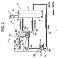
- a direct methanol fuel cell system 2 includes a housing 4 defining an anode chamber 6 and a cathode chamber 8, a protonically conductive 10 but electronically non-conductive membrane (Protonically Conductive Membrane) and a catalyst, a mixing chamber 12, a fuel tank 14, and a water tank 16.
- the catalyst may be positioned anywhere within the anode and cathode chambers, but preferably is applied to one or both faces of the Protonically Conductive Membrane.
- Gas carrying conduits connect the anode chamber (via conduit 17) to each of the fuel tank (via conduit 18), the water tank (via conduit 20), and the mixing chamber (via conduit 22).
- the gas carrying conduits ferry anodically generated gaseous effluent, CO 2 in a DMFC System, from the anode chamber to one or more of the other elements of the fuel cell.
- Each conduit also includes a valve to control the flow within a particular conduit.
- gas conduit 17 includes valve 17A
- gas conduit 18 includes valve 18A
- gas conduit 20 includes valve 20A
- gas conduit 22 includes valve 22A.
- a gas separator (not shown) may be incorporated using methods well known in the art.
- Liquid-carrying conduits carry fuel and water from the fuel tank (via conduit 24)and the water tank(via conduit 26), respectively, to the mixing chamber. Additional liquid conduits ferry fuel mixture from the mixing chamber (via conduit 28) to the anode chamber, and liquid effluent (un-reacted methanol and water) from the anode chamber to the mixing chamber.
- Each of the liquid carrying conduits also includes a valve to control the flow therein. Accordingly, conduit 24 includes valve 24A, conduit 26 includes valve 26A, conduit 28 includes valve 28A, and conduit 30 includes valve 30A.
- the anode chamber, the mixing chamber and the water tank are each equipped with a vent to the external environment, which can be opened to allow the pressure within each to be equalized with the ambient environment.
- fluids contained in respective chambers can be driven to another chamber or stirred, via a pressure differential developed between the chamber providing the fluid and the chamber receiving the fluid.
- pressure can be increased in the providing chamber above the pressure in the receiving chamber.
- the fluid carrying conduit between the two chambers includes a valve which is opened at an appropriate time to drive liquid from the providing chamber to the receiving chamber, once the pressure has reached a predetermined level.
- fluid may be moved to the anode chamber either directly (from the mixing chamber) or from the fuel and water tanks through the mixing chamber.
- unreacted methanol and water effluent from the anode chamber may be moved from the anode chamber to the mixing chamber through the coordinated opening and closing of the valves.
- an electrical load (not shown) is placed electrically between the anode chamber and cathode chamber of the fuel cell, thereby establishing a path for electrons produced in the anode chamber to be transported to the cathode chamber.
- the anode chamber includes an initial supply of an appropriate amount of fuel mixture and effluents have not yet been produced.
- first valve 17A (and associated valve positions) located along the gas carrying conduit 17 adjacent the anode chamber, it is not necessary.
- the operation of gas valves located adjacent the other elements render this first valve redundant, but conceptually allows for more efficient pressure capture and venting within the system.
- a pressure differential between the mixing chamber and the anode chamber is established by creating a closed sub-system comprising the anode chamber, the mixing chamber, and the gas carrying conduit connecting them. CO 2 generated in the anode chamber increases and produces a corresponding increase in pressure in the sub-system. Accordingly, the sub-system is established using the following valve positions: Valve Positions: Valve Status 17A Open 18A Closed 20A Closed 22A Open 24A Closed 26A Closed 28A Closed 30A Closed 38A Closed
- valves are positioned in the following manner: Valve Positions: Valve Status 17A Closed 18A Closed 20A Closed 22A Closed 24A Closed 26A Closed 28A Closed 30A Closed 38A Closed
- the anode vent is then opened to equalize the pressure therein with ambient pressure.
- the mixing chamber remains at the higher pressure, a pressure differential between the two chambers is established.
- valves are positioned in the following manner: Valve Positions: Valve Status 17A Closed* 18A Closed 20A Closed 22A Closed* 24A Closed 26A Closed 28A Open 30A Closed 38A Closed *Valves may remain open, but are preferably closed
- the anode vent may be thereafter closed, or may remain open during the fluid transfer. However, for a next pressure driven function to occur, the anode vent must be closed so that the CO 2 gas may be efficiently used to create a required pressure differential between the chambers where the fluid transfer will take place.
- a pressure differential between the water chamber and the mixing chamber is established by creating a closed sub-system comprising the anode chamber, the water chamber, and the gas carrying conduit connecting them. CO 2 generated in the anode chamber increases and produces a corresponding increase in pressure in the sub-system. Accordingly, the sub-system is established using the following valve positions: Valve Positions: Valve Status 17A Open 18A Closed 20A Open 22A Closed 24A Closed 26A Closed 28A Closed 30A Closed 38A Closed
- valves are positioned in the following manner: Valve Positions: Valve Status 17A Closed 18A Closed 20A Closed 22A Closed 24A Closed 26A Closed 28A Closed 30A Closed 38A Closed
- the water chamber Since the water chamber is at a pressure higher than ambient, it is also therefore higher than the pressure in the mixing chamber thereby establishing the pressure differential between the two chambers.
- Valve Positions Valve Status 17A Closed* 18A Closed 20A Closed* 22A Closed 24A Closed 26A Open 28A Closed 30A Closed 38A Closed * Valves may remain open, but are preferably closed.
- the anode vent may be open after valve 20A has been closed, or may remain closed. For a next pressure driven function to occur, however, the anode vent must be closed so that the CO 2 gas may be efficiently used to create a required pressure differential between the chambers where the fluid transfer will take place.
- Function 3 Add fuel to mixing chamber.
- a pressure differential between the fuel chamber and the mixing chamber is established by creating a closed sub-system comprising the anode chamber, the fuel chamber, and the gas carrying conduit connecting them. CO 2 generated in the anode chamber increases and produces a corresponding increase in pressure in the sub-system. Accordingly, the sub-system is established using the following valve positions Valve Positions: Valve Status 17A Open 18A Open 20A Closed 22A Closed 24A Closed 26A Closed 28A Closed 30A Closed 38A Closed
- valves are positioned in the following manner: Valve Positions: Valve Status 17A Closed 18A Closed 20A Closed 22A Closed 24A Closed 26A Closed 28A Closed 30A Closed 38A Closed
- the fuel chamber is at a pressure higher than ambient, it is also therefore higher than the pressure in the mixing chamber thereby establishing the pressure differential between the two chambers.
- Valve Positions Valve Status 17A Closed* 18A Closed* 20A Closed 22A Closed 30A Closed 24A Open 26A Closed 28A Open 38A Closed
- Valves may remain open, but are preferably closed.
- the anode vent may be open after valve 18A has been closed, or may remain closed. For a next pressure driven function to occur, however, the anode vent must be closed so that the CO 2 gas may be efficiently used to create a required pressure differential between the chambers where the fluid transfer will take place.
- Function 4 Move liquid effluent from anode chamber to mixing chamber.
- a pressure differential between the anode chamber and the mixing chamber is established by isolating the anode chamber from the remainder of the system. CO 2 generated in the anode chamber increases and produces a corresponding increase in pressure. Accordingly, the anode vent is closed and the valves are placed in the following positions: Valve Positions: Valve Status 17A Closed 18A Closed 20A Closed 22A Closed 30A Closed 24A Closed 26A Closed 28A Closed 38A Closed
- valves are positioned in the following manner to send liquid effluent to the mixing chamber from the anode chamber: Valve Positions: Valve Status 17A Closed 18A Closed 20A Closed 22A Closed 24A Closed 26A Closed 28A Closed 30A Open 38A Closed
- the CO 2 generated in the anode chamber may be vented to the ambient environment, or used to create pressure differentials within the fuel cell system.
- Function 5 Stir fuel mixture in the mixing chamber.
- a pressure differential between the anode chamber and the mixing chamber is established by isolating the anode chamber from the remainder of the system. CO 2 generated in the anode chamber increases and produces a corresponding increase in pressure. Accordingly, the anode vent is closed and the valves are placed in the following positions: Valve Positions: Valve Status 17A Closed 18A Closed 20A Closed 22A Closed 24A Closed 26A Closed 28A Closed 30A Closed 38A Closed
- valves are positioned in the following manner to send CO2 flowing through the mixing chamber from the anode chamber to the mixing chamber in order to agitate the fuel-water mixture: Valve Positions: Valve Status 17A Open 18A Closed 20A Closed 22A Open 24A Closed 26A Closed 28A Closed 30A Closed 38A Closed
- Water generate on the cathode may be moved from the cathode to the water tank via a wicking agent, and/or by other systems including use of the system described in associated U.S. application No. 09/818,290, filed March 27,2001 , entitled, METHODS AND APPARATUSES FOR MANAGING EFFLUENT PRODUCTS IN A DIRECT CONVERSION FUEL CELL SYSTEM (which is commonly owned by assignee of the present invention). Water generated on the cathode may also be removed to the water tank by other means known to those skilled in the art, including but not limited to gravity bases systems.
- a flexible impermeable membrane 200 may also be use to prevent the CO 2 from mixing with the various liquids and bubbling out before creating the necessary pressure differential.
- valves of the invention may be electrically or mechanically actuated and may be fabricated using a variety of designs well known to those skilled in the art. Moreover, the fluid valves are preferably metering valves that may be used to control the amount of fluid that is released when actuated.
- a computer processor and associated supporting and peripheral systems may be used and programmed to actuate the valves according to the above functions.
- FIG. 3 illustrates a second embodiment according to the present invention.
- a direct methanol fuel cell system includes a housing 42 defining an anode chamber 44 having a vent 46 and a cathode chamber 48.
- the system includes a protonically conductive but electronically non-conductive membrane 50 (Protonically Conductive Membrane), a catalyst, a pump 52, a fuel tank 54, and a water tank 56.
- the catalyst may be positioned anywhere within the anode and cathode chambers, but preferably is applied to one or both sides of the Protonically Conductive Membrane 50.
- the pump includes, but is not limited 10, a passively driven pump as disclosed in United States Patent Application No. 09/717,754, filed December 8, 2000 , entitled PASSIVELY PUMPE LIQUID FEED FUEL CELL SYSTEM, which is commonly owned by the assignee of the present invention.
- a gas coming conduit 58 connect die anode chamber to the fuel tank.
- Liquid-carrying conduits carry fuel and water form the fuel tank and the water tank via conduits 60 and 62, respectively, to the pump, fuel mixture from the pump to anode chamber via conduit 64, and liquid effluent from the anode chamber to the pump via conduit 66.
- An additional liquid conduit 68 may be included which transports liquid effluent from the cathode chamber to the water tank.
- a valve 60A controls the flow from the fuel tank to the pump.
- this embodiment utilizes CO 2 produced in the anode chamber to create a pressure differential between the fuel tank and a pump, so that when the fuel mixture is too lean (i.e, not enough fuel in the water/fuel mixture), fuel may be driven to the pump.
- the pump operates to force a fuel mixture into the anode chamber and for drawing liquid effluent from the anode chamber.
- a vent positioned on the pump allows for pressure within the pump to be equalized with ambient pressure, to insure that an adequate pressure differential between the fuel tank and the pump is created.
- pressure is increased in the fuel tank by closing the anode vent 46, opening valves 58A and 58B, and closing valve 60A.
- a pump vent 53 is opened to insure that the pressure therein is at a lower pressure, i.e., ambient pressure, than that of the fuel tank.
- valves 58A and 58B are closed (although either one or both may remain open), the anode vent 46 is opened, the pump vent 53 is closed, and valve 60A is opened. Fuel is then driven by the pressure differential to the pump.
- the fuel cell according to the fourth embodiment of the present invention is substantially similar to the DMFCs described in the first and second embodiments, except in place of the mixing chamber, a recirculation conduit 69 is included. Specifically, liquid effluent from the anode chamber 70 is circulated through the conduit from one end of the anode chamber to the other end.
- the fuel tank 72 provides fuel to the recirculation conduit through a conduit 74 and 74A fuel valve.
- the water tank supplies water to the recirculation conduit through a conduit 80 and 80A water valve.
- a gas conduit 84 delivers effluent gas from the anode chamber 70 to each of the fuel tank 72 and water tank 78 via conduit 71 and associated valve 71A and conduit 77 and associated valve 77A, respectively. Effluent from the cathode chamber 75 may be delivered to the water tank 78 via liquid conduit 79 and valve 79A.
- an anode vent 73 is closed, valves 84A and 71A are opened, and valves 77A, 74A, 80A and 79A are closed.
- the increasing volume of CO 2 produced in the anode chamber increases the pressure of the anode chamber/fuel tank.
- valves 84A and/or 71A are then closed and the anode vent is opened to equalize the pressure therein to ambient pressure, thereby establishing a pressure differential between the fuel tank and the recirculation conduit/anode chamber.
- the anode vent is closed and valve 74A is opened.
- the pressure differential drives the fuel from the fuel tank and into the recirculation conduit.
- the same process is used to deliver water to the fuel mixture.
- the anode vent 73 is closed, valves 84A and 77A are opened, and valves 71A, 74A, 80A and 79A are closed.
- valves 84A and/or 77A are closed and the anode vent is opened. Opening the anode vent, of course, equalizes the pressure therein to ambient, creating the necessary pressure differential between the water tank and the anode chamber.
- the anode vent is then closed, and valve 80A is opened , driving water into the fuel mixture.
- Figure 5 illustrates a similar design to that of Figure 4 , except in this case, the system does not include a water tank and associated conduits and valves. To drive fuel into the recirculation conduit, the procedure described in association with Figure 4 is followed. Additional water, if necessary, may be provided from the cathode chamber to maintain the proper fuel-water mixture.
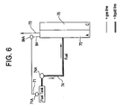
- Figure 6 illustrates yet another alternative design to that of Figures 4 and 5 . Specifically, in this embodiment, fuel is supplied directly into the anode chamber without being diluted, being driven in the same procedure as that described in association with the third and fourth embodiments.
- Figure 8 illustrates the sixth embodiment not belonging to the invention relating to a method and system for determining an appropriate level of fuel in a fuel mixture for a DMFC. This system will be described with reference to the system illustrated in Fig. 2 .
- a fuel concentration sensor 21 located within the system is used to determine a first concentration level of fuel in the fuel mixture.
- the fuel tank and the water tank supplies fuel and water, respectively, to the fuel mixture using the methods according to the previous embodiments.
- the fuel cell system, and specifically the gaseous and liquid valves, and vents are operated and controlled via a controller 100 as shown in Fig 9.
- Fig. 9 illustrates the controller in communication with each one of the valves and vents of the fuel cell system.
- the controller also includes a memory 102 containing a look-up table having data associated with fuel levels in the fuel mixture for specific operating parameters.
- a clock/timer 106 is used to measure time between obtaining fuel concentration levels.
- an electrical meter or other device which measures the electrical output of the fuel cell system may be used to determine when to re-measure the fuel concentration level.
- the system monitors the fuel level in the fuel mixture as well as the electricity that is being required of the system using a metering device 104. Accordingly, the system obtains the current fuel concentration compares (step S1) and it with a fuel level required for a particular condition using the look-up table (step S2). If the fuel mixture is too lean, requiring more fuel from the tank, the system opens/closes the appropriate vents and valves to drive fuel into the fuel mixture (steps S7), S8). If the fuel mixture is too rich, requiring more water from the water tank, the system responses appropriately (steps S4, S5).
- step S6 Each time fuel or water is added, a period of time is pre-programmed to elapse so that the component can adequately mix with the pre-existing mixture (step S6). Otherwise, the fud level sensor might obtain a false reading and supply fuel or water to die system at an inappropriate time. This would eventually lead to inefficient operation of the DMFC. potentially resulting in failure of the fuel cell system.
- controller of Fig. 9 and the method outlined in Fig. 8 not belonging to the invention may be used with any of the above-described embodiments of the invention.
- the controller was illustrated in communication with the valves and vents as shown in Fig. 2 .
Landscapes
- Life Sciences & Earth Sciences (AREA)
- Engineering & Computer Science (AREA)
- Manufacturing & Machinery (AREA)
- Sustainable Development (AREA)
- Sustainable Energy (AREA)
- Chemical & Material Sciences (AREA)
- Chemical Kinetics & Catalysis (AREA)
- Electrochemistry (AREA)
- General Chemical & Material Sciences (AREA)
- Fuel Cell (AREA)
Applications Claiming Priority (3)
| Application Number | Priority Date | Filing Date | Title |
|---|---|---|---|
| US855982 | 2001-05-15 | ||
| US09/855,982 US6686081B2 (en) | 2001-05-15 | 2001-05-15 | Methods and apparatuses for a pressure driven fuel cell system |
| PCT/US2002/015086 WO2002093675A2 (en) | 2001-05-15 | 2002-05-14 | Methods and apparatuses for a pressure driven fuel cell system |
Publications (2)
| Publication Number | Publication Date |
|---|---|
| EP1393396A2 EP1393396A2 (en) | 2004-03-03 |
| EP1393396B1 true EP1393396B1 (en) | 2008-03-05 |
Family
ID=25322606
Family Applications (1)
| Application Number | Title | Priority Date | Filing Date |
|---|---|---|---|
| EP02736784A Expired - Lifetime EP1393396B1 (en) | 2001-05-15 | 2002-05-14 | Methods and apparatuses for a pressure driven fuel cell system |
Country Status (6)
| Country | Link |
|---|---|
| US (2) | US6686081B2 (ko) |
| EP (1) | EP1393396B1 (ko) |
| JP (1) | JP2004527091A (ko) |
| AT (1) | ATE388496T1 (ko) |
| DE (1) | DE60225442D1 (ko) |
| WO (1) | WO2002093675A2 (ko) |
Families Citing this family (48)
| Publication number | Priority date | Publication date | Assignee | Title |
|---|---|---|---|---|
| US6914671B2 (en) * | 2000-09-18 | 2005-07-05 | Focke & Co. (Gmbh) | Method and apparatus for the inspection of objects |
| US6824899B2 (en) * | 2000-11-22 | 2004-11-30 | Mti Microfuel Cells, Inc. | Apparatus and methods for sensor-less optimization of methanol concentration in a direct methanol fuel cell system |
| JP3748417B2 (ja) * | 2002-03-29 | 2006-02-22 | 株式会社東芝 | 直接型液体燃料燃料電池発電装置およびその制御方法 |
| US7105245B2 (en) * | 2002-07-03 | 2006-09-12 | Neah Power Systems, Inc. | Fluid cell system reactant supply and effluent storage cartridges |
| JP3811115B2 (ja) * | 2002-09-30 | 2006-08-16 | 株式会社東芝 | 液体燃料電池デバイス |
| JP3912249B2 (ja) * | 2002-09-30 | 2007-05-09 | 日本電気株式会社 | 燃料電池の運転方法および燃料電池を搭載した携帯機器 |
| JP3821081B2 (ja) * | 2002-09-30 | 2006-09-13 | 日本電気株式会社 | 燃料電池およびこれを搭載した携帯機器ならびに燃料電池の運転方法 |
| US6989206B2 (en) * | 2002-11-13 | 2006-01-24 | Agilent Technologies, Inc. | Water recycling in fuel cell systems |
| US20040121218A1 (en) * | 2002-12-09 | 2004-06-24 | Craig Andrews | Fuel cell water management |
| US7501008B2 (en) * | 2003-01-31 | 2009-03-10 | Microcell Corporation | Hydrogen storage systems and fuel cell systems with hydrogen storage capacity |
| KR100519767B1 (ko) * | 2003-04-11 | 2005-10-10 | 삼성에스디아이 주식회사 | 센서를 구비하는 연료 전지의 연료량 공급 조절 시스템 |
| US7282293B2 (en) * | 2003-04-15 | 2007-10-16 | Mti Microfuel Cells Inc. | Passive water management techniques in direct methanol fuel cells |
| US7407721B2 (en) * | 2003-04-15 | 2008-08-05 | Mti Microfuel Cells, Inc. | Direct oxidation fuel cell operating with direct feed of concentrated fuel under passive water management |
| US7553571B2 (en) * | 2003-04-15 | 2009-06-30 | The Gillette Company | Management system for a fuel cell and method thereof |
| US7582371B2 (en) * | 2003-06-09 | 2009-09-01 | Panasonic Corporation | Fuel cell system having fuel and water controlling means |
| US20050026027A1 (en) * | 2003-06-19 | 2005-02-03 | Kabushiki Kaisha Toshiba | Fuel cell system |
| US20060222923A1 (en) * | 2003-07-01 | 2006-10-05 | Yasuyuki Muramatsu | Direct methanol fuel cell system |
| AU2003247903A1 (en) * | 2003-07-02 | 2005-02-15 | Neah Power Systems, Inc. | Closed liquid feed fuel cell systems and reactant supply and effluent storage cartridges adapted for use with the same |
| JP4697380B2 (ja) * | 2003-07-07 | 2011-06-08 | ソニー株式会社 | 燃料電池装置及び燃料電池の燃料供給方法 |
| JP4843898B2 (ja) * | 2003-10-08 | 2011-12-21 | 株式会社日立製作所 | 燃料電池装置及びその制御方法 |
| KR100571821B1 (ko) | 2003-10-22 | 2006-04-17 | 삼성에스디아이 주식회사 | 직접메탄올 연료전지 및 이를 장착한 휴대용 컴퓨터 |
| JP4432650B2 (ja) * | 2004-04-26 | 2010-03-17 | 株式会社日立製作所 | 燃料電池電源とその運転方法および燃料電池電源を用いた携帯用電子機器 |
| JP2005327626A (ja) * | 2004-05-14 | 2005-11-24 | Kurita Water Ind Ltd | 燃料電池発電システム |
| US20050282060A1 (en) * | 2004-06-18 | 2005-12-22 | Mti Micro Fuel Cells, Inc. | Fuel cell endplate system |
| JP4152360B2 (ja) | 2004-07-29 | 2008-09-17 | 三洋電機株式会社 | 燃料電池システム |
| WO2006013752A1 (ja) * | 2004-08-02 | 2006-02-09 | Matsushita Electric Industrial Co., Ltd. | 燃料電池用燃料供給機構 |
| EP1793439A4 (en) * | 2004-08-04 | 2007-10-24 | Nec Corp | FUEL CELL INSTALLATION AND MOBILE ELECTRONIC DEVICE THEREFOR |
| JP4601356B2 (ja) * | 2004-08-19 | 2010-12-22 | 富士通株式会社 | 循環型液体燃料電池及びその制御方法 |
| JP4709518B2 (ja) * | 2004-09-29 | 2011-06-22 | 株式会社東芝 | プロトン伝導膜及び燃料電池 |
| ES2280878T3 (es) * | 2004-11-02 | 2007-09-16 | Siemens Aktiengesellschaft | Procedimiento para el funcionamiento de una instalacion de celulas de combustible asi como instalacion de celulas de combustible. |
| JP2006147179A (ja) * | 2004-11-16 | 2006-06-08 | Toshiba Corp | 燃料電池ユニット |
| CN100369305C (zh) * | 2004-12-30 | 2008-02-13 | 比亚迪股份有限公司 | 一种燃料电池 |
| KR100626089B1 (ko) * | 2004-12-31 | 2006-09-21 | 삼성에스디아이 주식회사 | 액체연료 혼합장치 및 이를 구비한 직접액체연료전지 시스템 |
| JP2006221862A (ja) * | 2005-02-08 | 2006-08-24 | Toshiba Corp | 燃料電池 |
| DE102005015660B4 (de) * | 2005-04-06 | 2013-03-28 | Forschungszentrum Jülich GmbH | Niedertemperatur-Brennstoffzellenstapel sowie Verfahren zum Betreiben desselben |
| EP1760816A3 (en) * | 2005-08-31 | 2010-05-05 | Samsung SDI Co., Ltd. | Method and apparatus for water management in direct methanol fuel cell system using heat exchanger |
| KR100682865B1 (ko) * | 2005-10-19 | 2007-02-15 | 삼성에스디아이 주식회사 | 물 회수 시스템 및 이를 구비한 직접액체 연료전지 |
| KR100673755B1 (ko) * | 2005-10-21 | 2007-01-24 | 삼성에스디아이 주식회사 | 무펌프 구동 연료전지 시스템 |
| KR101252839B1 (ko) * | 2006-03-03 | 2013-04-09 | 삼성에스디아이 주식회사 | 회수장치를 채용한 연료전지 |
| KR100729071B1 (ko) * | 2006-05-19 | 2007-06-14 | 삼성에스디아이 주식회사 | 연료공급장치 하우징 및 이를 이용하는 주변장치 모듈 |
| JP2010509736A (ja) * | 2006-11-07 | 2010-03-25 | ポリフューエル・インコーポレイテッド | 燃料電池から生成される液状水の受動的回収 |
| KR100958033B1 (ko) * | 2007-10-30 | 2010-05-17 | 삼성에스디아이 주식회사 | 연료전지 스택의 성능을 조절하는 방법 및 장치와 그방법을 이용하는 직접 메탄올형 연료전지 |
| EP2294644A4 (en) * | 2008-06-04 | 2013-05-22 | Cellera Inc | ALKALINE MEMBRANE FUEL CELLS AND APPARATUS AND METHOD FOR INTRODUCING WATER INSIDE THERETO |
| JP2010040202A (ja) * | 2008-07-31 | 2010-02-18 | Fujikura Ltd | ダイレクトアルコール型燃料電池 |
| US8304368B2 (en) * | 2009-02-23 | 2012-11-06 | Cellera, Inc. | Catalyst coated membrane (CCM) and catalyst film/layer for alkaline membrane fuel cells and methods of making same |
| JP5806669B2 (ja) * | 2009-08-24 | 2015-11-10 | セルエラ, インコーポレイテッド | アルカリ燃料電池における空気co2に対する耐性を確保するシステムおよび方法 |
| JP6073036B2 (ja) | 2010-06-07 | 2017-02-01 | セルエラ, インコーポレイテッド | 膜電解質型燃料電池における触媒/膜表面付着のための化学結合 |
| US9472818B2 (en) * | 2013-06-17 | 2016-10-18 | GM Global Technology Operations LLC | Fuel cell water drain valve control with vehicle tilt compensation |
Family Cites Families (24)
| Publication number | Priority date | Publication date | Assignee | Title |
|---|---|---|---|---|
| GB1513130A (en) * | 1974-11-18 | 1978-06-07 | Exxon Research Engineering Co | Fuel cells and methods of operating them |
| US4155712A (en) * | 1976-04-12 | 1979-05-22 | Taschek Walter G | Miniature hydrogen generator |
| JPS5816471A (ja) | 1981-07-20 | 1983-01-31 | Nissan Motor Co Ltd | 液体燃料電池 |
| US4420544A (en) | 1981-10-02 | 1983-12-13 | California Institute Of Technology | High performance methanol-oxygen fuel cell with hollow fiber electrode |
| EP0181569B1 (en) | 1984-10-31 | 1991-05-02 | Hitachi, Ltd. | Liquid fuel cell |
| US4659634A (en) * | 1984-12-18 | 1987-04-21 | Struthers Ralph C | Methanol hydrogen fuel cell system |
| JPS61233976A (ja) * | 1985-04-10 | 1986-10-18 | Fuji Electric Co Ltd | 燃料電池設備 |
| JPS63202861A (ja) | 1987-02-18 | 1988-08-22 | Hitachi Ltd | メタノ−ル燃料電池 |
| JPH04274170A (ja) | 1991-03-01 | 1992-09-30 | Aisin Aw Co Ltd | 燃料電池 |
| US5165483A (en) * | 1991-05-01 | 1992-11-24 | Brunswick Corporation | Direct contact vapor generator fire suppression apparatus |
| US5599638A (en) | 1993-10-12 | 1997-02-04 | California Institute Of Technology | Aqueous liquid feed organic fuel cell using solid polymer electrolyte membrane |
| US5773162A (en) * | 1993-10-12 | 1998-06-30 | California Institute Of Technology | Direct methanol feed fuel cell and system |
| US5573866A (en) | 1995-05-08 | 1996-11-12 | International Fuel Cells Corp. | Direct methanol oxidation polymer electrolyte membrane power system |
| US5795496A (en) | 1995-11-22 | 1998-08-18 | California Institute Of Technology | Polymer material for electrolytic membranes in fuel cells |
| US5945231A (en) | 1996-03-26 | 1999-08-31 | California Institute Of Technology | Direct liquid-feed fuel cell with membrane electrolyte and manufacturing thereof |
| DE19722598B4 (de) | 1997-05-29 | 2006-11-09 | Areva Energietechnik Gmbh | Brennstoffzellensystem und Verfahren zum Betreiben eines Brennstoffzellensystems sowie dessen Verwendung in einer Anordnung zur unterbrechungsfreien Stromversorgung |
| US5992008A (en) | 1998-02-10 | 1999-11-30 | California Institute Of Technology | Direct methanol feed fuel cell with reduced catalyst loading |
| US5985474A (en) * | 1998-08-26 | 1999-11-16 | Plug Power, L.L.C. | Integrated full processor, furnace, and fuel cell system for providing heat and electrical power to a building |
| US6429019B1 (en) * | 1999-01-19 | 2002-08-06 | Quantum Group, Inc. | Carbon monoxide detection and purification system for fuels cells |
| JP3668069B2 (ja) * | 1999-09-21 | 2005-07-06 | 株式会社東芝 | 燃料電池用液体燃料収容容器および燃料電池 |
| US6503651B1 (en) * | 2000-04-19 | 2003-01-07 | Tvn Systems, Inc. | Methodology and apparatus for supply of reactant fluids to and purging of product and inert fluids from cells of fuel cell stack |
| US6387559B1 (en) * | 2000-07-18 | 2002-05-14 | Motorola, Inc. | Direct methanol fuel cell system and method of fabrication |
| US6497975B2 (en) * | 2000-12-15 | 2002-12-24 | Motorola, Inc. | Direct methanol fuel cell including integrated flow field and method of fabrication |
| US6534210B2 (en) * | 2001-01-16 | 2003-03-18 | Visteon Global Technologies, Inc. | Auxiliary convective fuel cell stacks for fuel cell power generation systems |
-
2001
- 2001-05-15 US US09/855,982 patent/US6686081B2/en not_active Expired - Lifetime
-
2002
- 2002-05-14 DE DE60225442T patent/DE60225442D1/de not_active Expired - Lifetime
- 2002-05-14 EP EP02736784A patent/EP1393396B1/en not_active Expired - Lifetime
- 2002-05-14 JP JP2002590442A patent/JP2004527091A/ja active Pending
- 2002-05-14 WO PCT/US2002/015086 patent/WO2002093675A2/en active Application Filing
- 2002-05-14 AT AT02736784T patent/ATE388496T1/de not_active IP Right Cessation
-
2003
- 2003-10-10 US US10/684,168 patent/US20040076859A1/en not_active Abandoned
Also Published As
| Publication number | Publication date |
|---|---|
| US6686081B2 (en) | 2004-02-03 |
| US20030031907A1 (en) | 2003-02-13 |
| EP1393396A2 (en) | 2004-03-03 |
| JP2004527091A (ja) | 2004-09-02 |
| WO2002093675A3 (en) | 2003-03-06 |
| ATE388496T1 (de) | 2008-03-15 |
| WO2002093675A2 (en) | 2002-11-21 |
| DE60225442D1 (de) | 2008-04-17 |
| US20040076859A1 (en) | 2004-04-22 |
Similar Documents
| Publication | Publication Date | Title |
|---|---|---|
| EP1393396B1 (en) | Methods and apparatuses for a pressure driven fuel cell system | |
| US7638215B2 (en) | Method of controlling delivery of fuel to a direct oxidation fuel cell | |
| CN100364161C (zh) | 燃料电池用填充回收器、燃料电池系统和燃料电池用填充回收器用再生器 | |
| JP5793782B2 (ja) | 燃料電池モジュールおよび燃料電池を遮断するプロセス | |
| CN100514733C (zh) | 燃料电池系统和燃料电池启动方法 | |
| EP1747599B1 (en) | Cartridge with fuel supply and membrane electrode assembly stack | |
| US4539086A (en) | Oxygen concentration controlling method and system | |
| CN100433429C (zh) | 液体燃料混合装置及采用它的直接液体给料燃料电池 | |
| US8900762B2 (en) | Fuel cell with recovering unit and method for driving the same | |
| US20090075128A1 (en) | Fuel cell system and method for controlling a fuel cell system | |
| US7597982B2 (en) | Fuel cell system with a gas supply pump that applies negative pressure to the anode and cathode | |
| JP2005203355A (ja) | 燃料電池システム及び燃料電池システムにおける発電方法 | |
| JP4282416B2 (ja) | 燃料電池および燃料電池用容器 | |
| EP1858105B1 (en) | Fuel cell system with an integrated fuel recycling module | |
| US8206868B2 (en) | Direct liquid feed fuel cell system having double fuel storage | |
| US20070125696A1 (en) | Device and method for increasing the concentration of fuel in a liquid flow supplied to the anode of a fuel cell | |
| JP2008218030A (ja) | 燃料電池 | |
| JP2006073214A (ja) | 燃料電池 | |
| JP2008218056A (ja) | 燃料電池 | |
| Becerra et al. | Ren et al. | |
| JP2008218057A (ja) | 燃料電池 | |
| JP2009099464A (ja) | チューブ型燃料電池 |
Legal Events
| Date | Code | Title | Description |
|---|---|---|---|
| PUAI | Public reference made under article 153(3) epc to a published international application that has entered the european phase |
Free format text: ORIGINAL CODE: 0009012 |
|
| 17P | Request for examination filed |
Effective date: 20031208 |
|
| AK | Designated contracting states |
Kind code of ref document: A2 Designated state(s): AT BE CH CY DE DK ES FI FR GB GR IE IT LI LU MC NL PT SE TR |
|
| AX | Request for extension of the european patent |
Extension state: AL LT LV MK RO SI |
|
| 17Q | First examination report despatched |
Effective date: 20040705 |
|
| GRAP | Despatch of communication of intention to grant a patent |
Free format text: ORIGINAL CODE: EPIDOSNIGR1 |
|
| GRAS | Grant fee paid |
Free format text: ORIGINAL CODE: EPIDOSNIGR3 |
|
| GRAA | (expected) grant |
Free format text: ORIGINAL CODE: 0009210 |
|
| AK | Designated contracting states |
Kind code of ref document: B1 Designated state(s): AT BE CH CY DE DK ES FI FR GB GR IE IT LI LU MC NL PT SE TR |
|
| REG | Reference to a national code |
Ref country code: GB Ref legal event code: FG4D |
|
| REG | Reference to a national code |
Ref country code: CH Ref legal event code: EP |
|
| REG | Reference to a national code |
Ref country code: IE Ref legal event code: FG4D |
|
| REF | Corresponds to: |
Ref document number: 60225442 Country of ref document: DE Date of ref document: 20080417 Kind code of ref document: P |
|
| PG25 | Lapsed in a contracting state [announced via postgrant information from national office to epo] |
Ref country code: ES Free format text: LAPSE BECAUSE OF FAILURE TO SUBMIT A TRANSLATION OF THE DESCRIPTION OR TO PAY THE FEE WITHIN THE PRESCRIBED TIME-LIMIT Effective date: 20080616 Ref country code: FI Free format text: LAPSE BECAUSE OF FAILURE TO SUBMIT A TRANSLATION OF THE DESCRIPTION OR TO PAY THE FEE WITHIN THE PRESCRIBED TIME-LIMIT Effective date: 20080305 |
|
| PG25 | Lapsed in a contracting state [announced via postgrant information from national office to epo] |
Ref country code: AT Free format text: LAPSE BECAUSE OF FAILURE TO SUBMIT A TRANSLATION OF THE DESCRIPTION OR TO PAY THE FEE WITHIN THE PRESCRIBED TIME-LIMIT Effective date: 20080305 |
|
| NLV1 | Nl: lapsed or annulled due to failure to fulfill the requirements of art. 29p and 29m of the patents act | ||
| PG25 | Lapsed in a contracting state [announced via postgrant information from national office to epo] |
Ref country code: BE Free format text: LAPSE BECAUSE OF FAILURE TO SUBMIT A TRANSLATION OF THE DESCRIPTION OR TO PAY THE FEE WITHIN THE PRESCRIBED TIME-LIMIT Effective date: 20080305 |
|
| PG25 | Lapsed in a contracting state [announced via postgrant information from national office to epo] |
Ref country code: NL Free format text: LAPSE BECAUSE OF FAILURE TO SUBMIT A TRANSLATION OF THE DESCRIPTION OR TO PAY THE FEE WITHIN THE PRESCRIBED TIME-LIMIT Effective date: 20080305 Ref country code: PT Free format text: LAPSE BECAUSE OF FAILURE TO SUBMIT A TRANSLATION OF THE DESCRIPTION OR TO PAY THE FEE WITHIN THE PRESCRIBED TIME-LIMIT Effective date: 20080805 Ref country code: SE Free format text: LAPSE BECAUSE OF FAILURE TO SUBMIT A TRANSLATION OF THE DESCRIPTION OR TO PAY THE FEE WITHIN THE PRESCRIBED TIME-LIMIT Effective date: 20080605 |
|
| EN | Fr: translation not filed | ||
| PG25 | Lapsed in a contracting state [announced via postgrant information from national office to epo] |
Ref country code: MC Free format text: LAPSE BECAUSE OF NON-PAYMENT OF DUE FEES Effective date: 20080531 |
|
| REG | Reference to a national code |
Ref country code: CH Ref legal event code: PL |
|
| PLBE | No opposition filed within time limit |
Free format text: ORIGINAL CODE: 0009261 |
|
| STAA | Information on the status of an ep patent application or granted ep patent |
Free format text: STATUS: NO OPPOSITION FILED WITHIN TIME LIMIT |
|
| PG25 | Lapsed in a contracting state [announced via postgrant information from national office to epo] |
Ref country code: LI Free format text: LAPSE BECAUSE OF NON-PAYMENT OF DUE FEES Effective date: 20080531 Ref country code: DK Free format text: LAPSE BECAUSE OF FAILURE TO SUBMIT A TRANSLATION OF THE DESCRIPTION OR TO PAY THE FEE WITHIN THE PRESCRIBED TIME-LIMIT Effective date: 20080305 Ref country code: CH Free format text: LAPSE BECAUSE OF NON-PAYMENT OF DUE FEES Effective date: 20080531 Ref country code: DE Free format text: LAPSE BECAUSE OF FAILURE TO SUBMIT A TRANSLATION OF THE DESCRIPTION OR TO PAY THE FEE WITHIN THE PRESCRIBED TIME-LIMIT Effective date: 20080606 |
|
| 26N | No opposition filed |
Effective date: 20081208 |
|
| GBPC | Gb: european patent ceased through non-payment of renewal fee |
Effective date: 20080605 |
|
| PG25 | Lapsed in a contracting state [announced via postgrant information from national office to epo] |
Ref country code: IE Free format text: LAPSE BECAUSE OF NON-PAYMENT OF DUE FEES Effective date: 20080514 Ref country code: FR Free format text: LAPSE BECAUSE OF FAILURE TO SUBMIT A TRANSLATION OF THE DESCRIPTION OR TO PAY THE FEE WITHIN THE PRESCRIBED TIME-LIMIT Effective date: 20081226 |
|
| PG25 | Lapsed in a contracting state [announced via postgrant information from national office to epo] |
Ref country code: GB Free format text: LAPSE BECAUSE OF NON-PAYMENT OF DUE FEES Effective date: 20080605 |
|
| PG25 | Lapsed in a contracting state [announced via postgrant information from national office to epo] |
Ref country code: IT Free format text: LAPSE BECAUSE OF FAILURE TO SUBMIT A TRANSLATION OF THE DESCRIPTION OR TO PAY THE FEE WITHIN THE PRESCRIBED TIME-LIMIT Effective date: 20080305 |
|
| PG25 | Lapsed in a contracting state [announced via postgrant information from national office to epo] |
Ref country code: CY Free format text: LAPSE BECAUSE OF FAILURE TO SUBMIT A TRANSLATION OF THE DESCRIPTION OR TO PAY THE FEE WITHIN THE PRESCRIBED TIME-LIMIT Effective date: 20080305 |
|
| PG25 | Lapsed in a contracting state [announced via postgrant information from national office to epo] |
Ref country code: LU Free format text: LAPSE BECAUSE OF NON-PAYMENT OF DUE FEES Effective date: 20080514 |
|
| PG25 | Lapsed in a contracting state [announced via postgrant information from national office to epo] |
Ref country code: TR Free format text: LAPSE BECAUSE OF FAILURE TO SUBMIT A TRANSLATION OF THE DESCRIPTION OR TO PAY THE FEE WITHIN THE PRESCRIBED TIME-LIMIT Effective date: 20080305 |
|
| PG25 | Lapsed in a contracting state [announced via postgrant information from national office to epo] |
Ref country code: GR Free format text: LAPSE BECAUSE OF FAILURE TO SUBMIT A TRANSLATION OF THE DESCRIPTION OR TO PAY THE FEE WITHIN THE PRESCRIBED TIME-LIMIT Effective date: 20080606 |