EP1385630B1 - Mehrwalzenbrecher - Google Patents
Mehrwalzenbrecher Download PDFInfo
- Publication number
- EP1385630B1 EP1385630B1 EP02737916A EP02737916A EP1385630B1 EP 1385630 B1 EP1385630 B1 EP 1385630B1 EP 02737916 A EP02737916 A EP 02737916A EP 02737916 A EP02737916 A EP 02737916A EP 1385630 B1 EP1385630 B1 EP 1385630B1
- Authority
- EP
- European Patent Office
- Prior art keywords
- crushing
- roller
- teeth
- crusher according
- rollers
- Prior art date
- Legal status (The legal status is an assumption and is not a legal conclusion. Google has not performed a legal analysis and makes no representation as to the accuracy of the status listed.)
- Expired - Lifetime
Links
Images







Classifications
-
- B—PERFORMING OPERATIONS; TRANSPORTING
- B02—CRUSHING, PULVERISING, OR DISINTEGRATING; PREPARATORY TREATMENT OF GRAIN FOR MILLING
- B02C—CRUSHING, PULVERISING, OR DISINTEGRATING IN GENERAL; MILLING GRAIN
- B02C18/00—Disintegrating by knives or other cutting or tearing members which chop material into fragments
- B02C18/06—Disintegrating by knives or other cutting or tearing members which chop material into fragments with rotating knives
- B02C18/14—Disintegrating by knives or other cutting or tearing members which chop material into fragments with rotating knives within horizontal containers
- B02C18/142—Disintegrating by knives or other cutting or tearing members which chop material into fragments with rotating knives within horizontal containers with two or more inter-engaging rotatable cutter assemblies
-
- B—PERFORMING OPERATIONS; TRANSPORTING
- B02—CRUSHING, PULVERISING, OR DISINTEGRATING; PREPARATORY TREATMENT OF GRAIN FOR MILLING
- B02C—CRUSHING, PULVERISING, OR DISINTEGRATING IN GENERAL; MILLING GRAIN
- B02C4/00—Crushing or disintegrating by roller mills
- B02C4/02—Crushing or disintegrating by roller mills with two or more rollers
- B02C4/08—Crushing or disintegrating by roller mills with two or more rollers with co-operating corrugated or toothed crushing-rollers
-
- B—PERFORMING OPERATIONS; TRANSPORTING
- B02—CRUSHING, PULVERISING, OR DISINTEGRATING; PREPARATORY TREATMENT OF GRAIN FOR MILLING
- B02C—CRUSHING, PULVERISING, OR DISINTEGRATING IN GENERAL; MILLING GRAIN
- B02C4/00—Crushing or disintegrating by roller mills
- B02C4/28—Details
- B02C4/30—Shape or construction of rollers
-
- B—PERFORMING OPERATIONS; TRANSPORTING
- B02—CRUSHING, PULVERISING, OR DISINTEGRATING; PREPARATORY TREATMENT OF GRAIN FOR MILLING
- B02C—CRUSHING, PULVERISING, OR DISINTEGRATING IN GENERAL; MILLING GRAIN
- B02C4/00—Crushing or disintegrating by roller mills
- B02C4/28—Details
- B02C4/42—Driving mechanisms; Roller speed control
Definitions
- the invention relates to a multi-roll crusher for comminution mineral crushing material, the crushing rollers with radially projecting, itself both in the circumferential and in the axial direction extending crushing teeth are equipped.
- the practically possible comminution methods differ by the Type of stress or deformation of the particles to be comminuted Crushing chamber.
- the particles between two Roll surfaces are in the particles pressure, shear and Tensile stresses generated.
- the design of the roller surface and the Rotational speed determine the type of stress and Intensity.
- the counter-rotating crushing rollers are connected via a common Drive driven synchronously and point in circumferential and axial direction arranged crushing teeth, which are provided in the form of toothed rings.
- a common Drive driven synchronously and point in circumferential and axial direction arranged crushing teeth which are provided in the form of toothed rings.
- a plurality of Crushing teeth per toothed ring is given so that in the area of each other Combining individual crushing teeth of the two crushing rollers relative small crushing spaces formed in the catchment area above the crushing rollers become. It is shown that even larger glass articles captured by the teeth and are pre-crushed during a first crushing process. In the course the further reducing crushing gap of the counter-rotating Crushing rolls, a second post-shredding takes place.
- EP-B 0 167 178 describes a mineral crusher with two crushing rollers, the each a number of radially projecting from the roller Mineralbrecherzähnen, wherein the teeth on each roller in circumferentially extending, axially distributed along the roller at intervals Groups are arranged, the circumferentially extending groups of Teeth are arranged on a roller so that they are between adjacent circumferentially extending groups of teeth on the are other roller and axially spaced therefrom, so that in the opposing rotation of the rollers between the teeth of each group two axially spaced teeth in adjacent group of teeth on the run through another roller and thereby mineral clumps between them capture and cause it to break up or break up.
- each roller is arranged relative to each other and of a size and so Form that they circumferentially spaced a number of discrete spiral or helical, running along the roller training establish.
- Each roller thus includes a strin surface, located in Direction of the other end face extending sprialartig trained Tooth arrangements, wherein the spiral shape is the same or in opposite directions can be.
- the purpose of the spiral or helical design of the Brechzähne are justified therein, the material to be crushed in Transport longitudinal direction of the crushing rollers and on the transport route to crush.
- a co-directional arrangement of the spiral or However, helical tooth formation would make no sense here because no defined transport can take place. This is only in the opposite direction Arrangement possible.
- Such a trained mineral breaker has relatively little per toothed ring Teeth, seen in the circumferential direction, so that in counter-rotating Rolling already formed a larger crushing space, which is for crushing also serves larger piece goods.
- the disadvantage of this mineral crusher is that the good to be broken for the utilization of the transport effect in essential frontally must be abandoned, which - also by the Transport of the same seen in the longitudinal direction of the rollers - itself set different wear conditions.
- the document JP-A-09 136037 shows a multi-roll crusher according to the preamble of claim 1.
- the subject invention relates to a prior art, as he is formed by EP 0 167 178, namely a slow-running Double roll crusher.
- Such machines are used both for Crushing of medium-hard rock, as well as for caking tending materials used, that is brown and hard coal, limestone, Tonmerkel and similar raw materials.
- the parallel arranged, opposite rotating crushing rollers are - as in the generic part of the first To claim - equipped with crushing teeth whose size, Shape and configuration in interaction of both rolls a crushing space define the required quality of the discharge grain and the Ensure throughput during comminution.
- the invention is based on the object in the generic part of the to the first claim described Mehrwalzenbrecher to the effect optimize that by forming simultaneously effective primary compartments, im Contrary to EP 0 167 178 also significantly more coarse-grained proportions can be crushed in parallel and effectively in less time to order to achieve an increase in the effective crushing performance. Of the Wear is about, over the life of the multi-roll crusher seen over Adjust the roller length evenly.
- the subject invention thus relates to a crushing machine in which the crushing rollers with a few large tooth formations, over the circumference seen, are equipped.
- the ratio of outer roll diameter to Tooth height should be less than 5 to 1, the number of teeth, in Circumferential direction of each crushing roller should be considered low, e.g. on nine teeth is limited.
- the actual comminution process of the larger chunks of material begins in this case with a positive material feed. He is characterized that the chunks of material between two or more corresponding Crushing teeth of the crushing rollers are detected and a first size reduction Experienced. Upon further rotation of the crushing rollers is done by combing the corresponding dental arrays the training of secondary Crushing spaces in which the pre-broken or smaller material is trapped is claimed and in some areas on bending and shear. The Crushing takes place between Brechzähnen- and basic diameter of Crushing rollers, or between the tooth front and back of the tooth opposite crushing roller instead.
- the uniform Brech leopard alsoen over the circumference (toothed ring), are in the multi-roll crusher according to the invention, axially with a special Angular offset on a crushing roller arranged to each other, so that spatially trained to train two opposing rows of teeth, which in odd Number of toothed rings their apex in the area of the middle toothed ring have each crushing roller. With even number of toothed rings exists no middle toothed ring, so that the vertex set differently becomes.
- the opposite corresponding crushing roller is the same Tooth arrangement, seen over its length, equipped. In the plan view The crushing rollers in operation form such an opposite direction extending arrow shape, the total roll length in two about the same divided into large areas.
- a further embodiment of the invention can provide that the imaginary Connecting lines of the crushing teeth of each crushing roller under a corresponding offset to each other are provided.
- this special Arrangement are the uniform crushing tooth formations over the circumference (Toothed ring), axially with a special angular offset on a crushing roller arranged to each other, in the way that spatially two form opposing rows of teeth, which by a predetermined angle of Perimeter division offset from each other.
- the opposite corresponding roller is with the same tooth arrangement over which Roll length seen, equipped.
- This arrangement differs from the former arrangement in that the forming in the operating state catchment areas at Not combing the opposing rotating crushing rollers at the same time train, but one after the other.
- the Goal of a continuous shredding process / concentration of power even at small crushing roller lengths with low number of teeth / circumference implemented become.
- Deviating from the prior art thus takes place in the arrow arrangement continuous training of several deep, three-dimensional primary Crushing spaces for the simultaneous penetration of large chunks of material.
- Another parameter for optimizing the primary computing room design It is considered to drive crushing rollers asychronously.
- the optimal differential speed of the crushing rollers for a high frequency The training of primary computing can, for example, a Frequency converter or hydraulic motor to be controlled or regulated. The optimum differential speed depends on the procedural task and the number of teeth over the Scope.
- FIG. 1 shows the crushing rollers 1,2 in their normal state
- Figure 2 shows the Crushing rollers 1.2 in their settlement 1 ', 2' represents.
- the indicated points define crushing teeth 3,3 ', 4,4'.
- the crushing teeth 3,3 ', 4,4' of each Crushing roller 1.2 form Brech leopard phenomenon A, B, C, D, wherein the crushing teeth 3,3 ', 4,4' of each breaking tooth group A, B, C, D of the respective Crushing roller outer edge 1a, 2a, 1b, 2b, in the direction of the crushing roller center X-Y run.
- the uniform crushing tooth formations over the circumference (Ring gear) are in this crushing roller assembly axially with a special Angular offset on the crushing roller 1 to each other arranged such that form spatially considered two opposing rows of teeth that hers Vertex in the region of the central toothed ring 7 of the crushing roller. 1 have.
- the opposite corresponding crushing roller 2 is connected to the same tooth order, seen over the roll length, formed, wherein the Tooth rows 6,6 '(imaginary connecting lines) their vertex in the area of the associated central toothed ring 7 'have.
- the Tooth rows 6,6 '(imaginary connecting lines) their vertex in the area of the associated central toothed ring 7 'have.
- CD off the entire length of the roll in two divided even areas, which in the figures 7 to 11 closer is clarified.
- Figures 1 and 2 are the arrows thus formed directed towards each other.
- the imaginary Connecting lines 5,5 ', 6,6' rectilinear, with curved Embodiments of the scope are also included ( Figure 17), without to leave the arrow shape.
- Figures 3 and 4 show an alternative to Figures 1 and 2, wherein the imaginary connecting lines 5,5 'and 6,6' also to each other are provided that pointing away from each other arrows AB, CD become.
- the uniform arrangement of the crushing teeth 3,3 ', 4,4', over the Seen circumference (ring gear), results in two spatial view opposing rows of teeth 5,5 ', 6,6', which are their vertices in the area of middle toothed ring 7,7 'of each crushing roller 1,2 respectively Settlement 1 ', 2' own. Otherwise, the structure of the Brech leopard phenomenon A, B, C, D analogous to that according to. Figures 1 and 2 to look at.
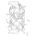
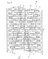
- FIG. 5 shows a plan view of a multi-roll crusher 10 according to FIG. 1 and 2. Identical components are provided with the same reference numerals. Visible are the crushing rollers 1, 2, which are mounted within a housing 11 are. The crushing rollers 1,2 are driven in opposite directions to each other (see Arrows). Recognizable are toothed rings 12,13 on which the breaking teeth 3,4 are mounted exchangeably.
- FIG. 5 is a snapshot of consecutive, continuously repeating crushing spaces, in this example, the primary crushing chamber B1 is recognizable formed through the imaginary connecting line extending along the breaking teeth 3, 4 5.6.
- FIG. 6 shows a side view of the multi-roll crusher 10, wherein the Breaking teeth 3.4 supporting ring gears 12,13 with, in the longitudinal direction of the Crushing rollers seen 1.2, offset from one another provided Brechzähnen 3.4 are recognizable. It can also be seen that surrounding the crushing rollers 1.2 Housing 11. Each crushing roller 1.2 carries each toothed ring 12,13 in this Example 4 crushing teeth 3.4, so that in the figures 1/2; 3/4 cited arrow-shaped profile results.
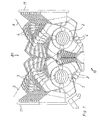
- FIGS. 7 to 9 show snapshots of the multi-roll crusher 10 arrow-shaped tooth arrangement in various perspective views.
- This with regard to the ever-changing crushing spaces B1, B2, B3.
- the same reference numerals apply to the same components.
- the crushing rollers 1,2 are within of the housing 11, wherein the crushing teeth 3,3 ', 4,4' between housing-side formations 14,15 can be passed.
- the training 14,15 have a special shape and are comb-like. she have the task of supplying the crushing space supplied material to the middle Direct refraction gap direct, without lifting the material in the Countercurrent occurs.
- FIG 7 an open roll surface formation is shown, i. a deep three-dimensional trough B1 for receiving large penetration Chunks of material. Due to the arrow-shaped arrangement of the crushing teeth 3,3 ', 4,4' in Connection with the given instantaneous roll positioning (Grip ein) can be elongated chunks of material in the over the Place the entire length of the roll towards the center of the deepening trough B1. By the two-sided free cut of the middle corresponding tooth pair 7,7 ' Both crushing rollers 1.2 a high crushing efficiency is achieved. The intake behavior is more favorable, the less the pair of teeth 7,7 'through adjacent teeth 3,3 ', 4,4' is disturbed.
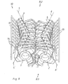
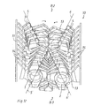
- FIG. 11 1 shows groups of teeth lying one behind the other AB; CD-forming crushing teeth 3,3 ', 4,4', where the imaginary connecting lines 5,5 ', 6,6', although they run towards each other, but not an ideal arrow give a staggered arrow shape.
- the imaginary Connecting lines 5,5 ', 6,6' with different angles of inclination to each other is a contour that is comparable to approximately 1 and 2, wherein Alternatively to Figures 3 and 4, a reverse arrangement of the crushing teeth 3,3 ', 4,4' is also conceivable.
- FIGS Figures 12-14 Further snapshots based on FIGS. 10 and 11 are shown in FIGS Figures 12-14 shown. Recognizable is the constant modification of the one after another forming refractive spaces B2, B3, where also the same Components are provided with the same reference numerals.
- each crushing roller 1.2 be driven synchronously, with each crushing roller 1.2 on not further illustrated associated drive means, such as gear, belt or the like.
- FIG. 15 shows the development 1 ', 2' of an arrow-shaped tooth arrangement an even number of toothed rings and different gradients or Inclination angles of the imaginary connecting lines 5,5 ', 6,6' of the individual Crusher tooth groups AB, CD. Except for the different gradients of the crushing teeth 3,3 ', 4,4' interconnecting lines 5,5 ', 6,6' this representation corresponds approximately to FIG. 2.
- FIG. 16 shows the development 1 ', 2' of an arrow-shaped tooth arrangement an even number of toothed rings and equal slopes or Inclination angles of the imaginary connecting lines 5,5 ', 6,6' and corresponds to such as that of Figure 2.
- FIG. 17 shows the unwinding 1 ', 2' of a curve segment (imaginary Connecting line 5,5 ', 6,6') arranged crushing teeth 3,3 ', 4,4' as an alternative to Figures 2,4,15 and 16.
- Type and arrangement of the crushing teeth 3,3 ', 4,4' on the crushing rollers 1,2 make the expert depending on the particular application.
- FIGS 18 and 19 form snapshots in asynchronous operation of Crushing rollers 1,2.
- the crushing rollers 1.2 do not have in this example further represented own drive means, such as transmission.
- the setting of the Differential speed of the two crushing rollers 1,2, for example, over a frequency converter are regulated.
- Recognizable is the primary crushing chamber B2.
- a secondary crushing space B4 which occurs during the further entry of the primarily broken material in the narrowing Crushing gap of the counter rotating Brachwalzen 1,2 forms.
- the axial angular offset of the toothed rings 12,13 determines the Slope of opposing imaginary connecting lines 5,5 ', 6,6' and becomes matched to the circumferential distribution, i. Number of crusher teeth 3,3 ', 4,4'.
- Optimal is an arrangement that runs continuously, i. to Passage of the first arrow engages the middle pair of teeth 7,7 'as the start of the following arrow to a continuous crushing operation guarantee.
- FIGS. 10 and 11 differs from those addressed in Figures 1 to 4 Arrow shapes such that the forming catchment areas B2, B3 at Combing the counter-rotating crushing rollers 1,2 not simultaneously form, but successively. if the one half of the roll is the primary one Having passed through catchment area B2, the primary intervention is carried out continuously the other half of the roll. Through this execution, the goal of a continuous crushing / power concentration even at small Roll lengths are implemented with small numbers of teeth per circumference.
- the Series connection of effectiveness can be the slope of the imaginary Connecting lines 5,5 ', 6,6' are reduced by half, compared to those shown in Figures 1 to 4 arrangement. Thereby can form larger catchment areas B2, B3.
- Both arrangements require a bilateral distribution function of the Center of crushing space for utilization of the entire roll width, especially for the larger chunks of material due to axial force components.
- the material will The multi-roll crusher is normally controlled via a feed conveyor fed, wherein the feed direction is transverse to the roll longitudinal direction can.
- the impact of the discharge parabola is targeted as possible provided between the counter-rotating crushing rollers 1.2.
- This arrangement is an energy and wear-intensive deflection of the Material flow avoided, especially the fines in the feed material by using the largest possible access level over the Roller length directly and with the lowest possible resistance and retention time be enforced.
Landscapes
- Engineering & Computer Science (AREA)
- Food Science & Technology (AREA)
- Crushing And Grinding (AREA)
- Crushing And Pulverization Processes (AREA)
- Saccharide Compounds (AREA)
Description
- Umfangsgeschwindigkeit
- Zahnkonfiguration oder Verteilung
- Zahnanordnung
- Rotor Positionierung
- Figuren 1 und 2
- Prinzipskizzen von gegensinnig rotierenden Brechwalzen eines nicht näher dargestellten Mehrwalzenbrechers sowie deren Abwicklungen
- Figuren 3 und 4
- Prinzipskizzen alternativer Ausgestaltungen von Brechwalzen sowie deren Abwicklungen
- Figur 5
- Draufsicht auf die Brechwalzen gem. Fig. 1 und 2 im Einbauzustand
- Figur 6
- Seitenansicht der Brechwalzen gem. Fig. 1 und 2 im Einbauszustand
- Figuren 7 bis 9
- Unterschiedliche Momentaufnahmen zur Erzeugung vergrößerter hintereinander liegender Brechraumbereiche in verschiedenen räumlichen Darstellungen (gemäß Figuren 1 und 2)
- Figuren 10 und 11
- Prinzipskizzen von zu Figuren 1 bis 4 alternativen Zahnanordnungen an Brechwalzen
- Figuren 12 bis 14
- Unterschiedliche Momentaufnahmen zur Erzeugung vergrößerter hintereinander liegender Brechraumbereiche in verschiedenen räumlichen Darstellungen (gemäß Figuren 10 und 11)
- Figur 15
- Abwicklung einer pfeilförmigen Zahnanordnung bei einer geraden Anzahl von Zahnringen und verschiedenen Steigungen
- Figur 16
- Abwicklung eine pfeilförmigen Zahnanordnung bei einer geraden Anzahl von Zahnringen und gleicher Steigung
- Figur 17
- Abwicklung einer kurvenartig vorgesehenen Zahnanordnung
- Figuren 18 und 19
- Momentaufnahmen bei asynchronem Betrieb der Brechwalzen unter Ausbildung primärer und sekundärer Brechräume
- es findet ein unverzögerter Materialeinzug größerer Materialbrocken durch dauerhafte, kontinuierliche Bereitstellung einer oder mehrerer Einzugsmöglichkeiten B1,B2,B3, über die gesamte Länge der Brechwalzen 1,2 gesehen, statt
- Durch die sich kontinuierlich schließenden verengenden Brechräume B1,B2,B3 wird beim Kämmen der gegenläufig rotierenden Brechwalzen 1,2 das Material durch die Krafteinleitung über die Brechzähne 3,3',4,4' in Teilbereichen auf Biegung und Scherung beansprucht und nicht auf Druck.
- es wird eine gleichmäßige fortschreitende Zerkleinerung in den maximal drei Beanspruchungszonen (primäre, sekundäre und ggf. tertiäre Zerkleinerung) erreicht, wobei es zu einer Aufteilung der Brechwalzenlänge in Bereiche kommt, in denen, in Umfangsrichtung gesehen, die primäre (B1-B3), sekundäre (B4) und ggf. tertiäre Zerkleinerung stattfindet. Die Übergänge sind hierbei fließend. Da die größten Zerkleinerungskräfte bei der primären Größenreduktion auftreten, können die installierten Zerkleinerungsdrehmomente geringer sein, da eine Konzentration der Kräfte auf wenige, sich im Einsatz befindliche Zahnpaare 3,4;3',4' gesehen ist. Die Beanspruchung der gesamten Maschinenelemente, speziell des Antriebes, erfolgt schonender mit geringerer Stoßbelastung. Die Dynamik des Belastungskollektivs wird vergleichmäßigt.
- infolge der speziellen Brechwalzenausbildung und der zusätzlichen Zerkleinerung durch den Einsatz eines Brechkammes in Verbindung mit der daraus resultierenden Beanspruchung der Materialien, kann die Spaltweite als definierter kleinster Abstand der Walzenoberflächen sowie der Zahnabstände untereinander wesentlich größer sein, als bei herkömmlichen Walzenbrechern, um die gewünschte Endkorngröße zu sichern.
- Materialtransport auf den Brechwalzen, d.h. die Erzeugung von axialen Kraftkomponenten auf das Material, speziell große Materialbrocken, um eine Furchung und als Folge daraus ein Festsetzen großer Materialbrocken zu vermeiden. Das Material bleibt stets in Bewegung, bis sich eine geeignete Einzugsstellung und Walzenposition ergibt.
- je nach Brechraumausbildung B1,B2,B3 bestimmt durch die Walzenausführung mit Zahnform und Anzahl über den Umfang, Anordung, Rotorpositionierung oder Brechbalkeneinsatz, kann die Kornanalyse des Endkorns eingestellt werden.
Claims (11)
- Mehrwalzenbrecher für die Zerkleinerung mineralischen Brechgutes, wobei die Brechwalzen (1, 2) mit radial vorstehenden, sich sowohl in Umfangs- als auch in Achslängsrichtung erstreckenden Brechzähnen (3, 3', 4, 4') ausgestattet und wobei - in der Draufsicht auf die Abwicklung (1', 2') einer jeden Brechwalze (1, 2) gesehen - die Brechzähne (3, 3', 4, 4') so angeordnet sind, daß sie mehrere hintereinander liegende Brechzahngruppen (A, B, C, D) bilden, deren gedachte Verbindungslinien (5, 5', 6, 6') unter einem vorgebbaren Neigungswinkel, bezogen auf die Abwicklung (1', 2'), von der jeweiligen Brechwalzenaußenkante (1a, 2a, 1b, 2b) in Richtung der Brechwalzenmitte (X, Y) aufeinander zu verlaufen, wobei zwischen den benachbarten und gegenüberliegenden Brechzähnen (3, 3', 4, 4') der Brechzahngruppen (A, B, C, D) im Einzugsbereich zwischen den gegenläufig rotierenden Brechwalzen (1, 2) sich kontinuierlich wiederholend primäre Brechräume (B1, B2, B3) entstehen, dadurch gekennzeichnet, daß die gedachten Verbindungslinien (5, 5', 6, 6') der Brechzahngruppen (A, B, C, D) einer jeden Brechwalze (1, 2), bezogen auf die Abwicklung (1', 2'), dergestalt aufeinander zu gerichtet sind; daß bei einem Zweiwalzenbrecher (10) aufeinander zu gerichtete Pfeile gebildet werden.
- Mehrwalzenbrecher nach Anspruch 1, dadurch gekennzeichnet, daß die gedachten Verbindungslinien (5, 5', 6, 6') der einzelnen Brechzahngruppen (A, B, C, D) als Geraden ausgebildet sind.
- Mehrwalzenbrecher nach Anspruch 1, dadurch gekennzeichnet, daß die gedachten Verbindungslinien (5, 5', 6, 6') der einzelnen Brechzahngruppen (A, B, C, D) Kurven vorgebbarer Krümmung sind.
- Mehrwalzenbrecher nach einem der Ansprüche 1 bis 3, dadurch gekennzeichnet, daß die einzelnen Brechzahngruppen (A, B, C, D) einer jeden Brechwalze (1, 2) im wesentlichen spiegelbildlich zueinander vorgesehen sind.
- Mehrwalzenbrecher nach einem der vorhergehenden Ansprüche, dadurch gekennzeichnet, daß die gedachten Verbindungslinien (5, 5', 6, 6') der einzelnen Brechzahngruppen (A, B, C, D) mit ungleichen Neigungswinkeln aufeinander zu verlaufen.
- Mehrwalzenbrecher nach einem der vorhergehenden Ansprüche, dadurch gekennzeichnet, daß das Verhältnis Walzenaußendurchmesser zu Zahnhöhe 5 : 1 beträgt, wobei die Zähnezahl in Umfangsrichtung einer jeden Brechwalze (1, 2) gering ist, insbesondere auf neun Zähne beschränkt ist.
- Mehrwalzenbrecher nach einem der vorhergehenden Ansprüche, dadurch gekennzeichnet, daß die Brechwalzen (1, 2) synchron, insbesondere über einen Einzel- oder Doppelantrieb, antreibbar sind.
- Mehrwalzenbrecher nach einem der vorhergehenden Ansprüche, dadurch gekennzeichnet, daß eine Brechwalze (1) als Masterwalze vorgesehen ist, während die andere Brechwalze (2) zur ungefähren Synchronisation bzw. Brechwalzenpositionierung einer dieser nachgeregelten Steuerung unterzogen wird.
- Mehrwalzenbrecher nach einem der Ansprüche 1 bis 6, dadurch gekennzeichnet, daß die Brechwalzen (1, 2) zur Erzielung einer optimalen Differenzgeschwindigkeit asynchron antreibbar sind.
- Mehrwalzenbrecher nach Anspruch 9, dadurch gekennzeichnet, daß jeder Brechwalze (1, 2) eigene Antriebsmittel, wie Einzel- oder Doppelantriebe, zugeordnet sind.
- Mehrwalzenbrecher nach einem der Ansprüche 9 bis 10, dadurch gekennzeichnet, daß die Differenzgeschwindigkeiten der Brechwalzen (1, 2) über mindestens einen Frequenzumrichter, einen Hydraulikantrieb oder ein mechanisches Untersetzungsgetriebe steuerbar bzw. regelbar sind.
Priority Applications (1)
| Application Number | Priority Date | Filing Date | Title |
|---|---|---|---|
| DK02737916T DK1385630T3 (da) | 2001-04-27 | 2002-04-03 | Multivalseknuser |
Applications Claiming Priority (3)
| Application Number | Priority Date | Filing Date | Title |
|---|---|---|---|
| DE10120765A DE10120765A1 (de) | 2001-04-27 | 2001-04-27 | Mehrwalzenbrecher |
| DE10120765 | 2001-04-27 | ||
| PCT/EP2002/003666 WO2002087767A1 (de) | 2001-04-27 | 2002-04-03 | Mehrwalzenbrecher |
Publications (2)
| Publication Number | Publication Date |
|---|---|
| EP1385630A1 EP1385630A1 (de) | 2004-02-04 |
| EP1385630B1 true EP1385630B1 (de) | 2005-06-08 |
Family
ID=7682996
Family Applications (1)
| Application Number | Title | Priority Date | Filing Date |
|---|---|---|---|
| EP02737916A Expired - Lifetime EP1385630B1 (de) | 2001-04-27 | 2002-04-03 | Mehrwalzenbrecher |
Country Status (12)
| Country | Link |
|---|---|
| US (1) | US7021577B2 (de) |
| EP (1) | EP1385630B1 (de) |
| CN (1) | CN1257015C (de) |
| AT (1) | ATE297253T1 (de) |
| AU (1) | AU2002312791B2 (de) |
| BR (1) | BR0209167B1 (de) |
| CA (1) | CA2443698C (de) |
| DE (2) | DE10120765A1 (de) |
| ES (1) | ES2242865T3 (de) |
| PT (1) | PT1385630E (de) |
| WO (1) | WO2002087767A1 (de) |
| ZA (1) | ZA200309109B (de) |
Cited By (1)
| Publication number | Priority date | Publication date | Assignee | Title |
|---|---|---|---|---|
| DE102013206341A1 (de) | 2013-04-10 | 2014-10-16 | Takraf Gmbh | Bogenförmige und polygonale Brechzahnanordnung bei Rotor- und Walzenbrechern |
Families Citing this family (25)
| Publication number | Priority date | Publication date | Assignee | Title |
|---|---|---|---|---|
| DE102005027729A1 (de) * | 2005-06-16 | 2006-12-28 | Khd Humboldt Wedag Gmbh | Walzenbrecher zum Brechen von heißem Zementklinker |
| JP5182001B2 (ja) * | 2008-02-29 | 2013-04-10 | 株式会社リコー | トナーの製造方法およびトナー造粒装置 |
| GB0817132D0 (en) * | 2008-09-19 | 2008-10-29 | Mmd Design & Consult | Mineral Sizer |
| US20100181405A1 (en) * | 2009-01-05 | 2010-07-22 | Royal Appliance Mfg. Co.D/B/A Tti Floor Care North America | Blade assembly for shredders of sheet-like material |
| GB2467744A (en) * | 2009-02-11 | 2010-08-18 | Gudmundur Orn Jensson | Comminuting machine |
| CN102172556B (zh) * | 2010-12-07 | 2013-02-13 | 东北大学 | 一种钒钛磁铁矿高压辊磨-预选加工方法 |
| US10195805B2 (en) * | 2013-01-16 | 2019-02-05 | Hermann Schwelling | Pressure roller for an apparatus for compaction of empty beverage containers |
| CN104069913B (zh) * | 2014-07-10 | 2016-01-13 | 太原重工股份有限公司 | 双齿辊破碎机 |
| CN104084259B (zh) * | 2014-08-01 | 2017-02-22 | 张珂 | 一种辊子及其辊压装置 |
| WO2016049120A1 (en) * | 2014-09-24 | 2016-03-31 | Jwc Enviornmental | High flow high capture side rails for comminutor |
| CN106475180A (zh) | 2015-08-31 | 2017-03-08 | 川崎重工业株式会社 | 冷却装置的辊式破碎机 |
| DE202016104868U1 (de) | 2016-09-05 | 2016-09-20 | Crush + Size Technology Gmbh & Co. Kg | Zweiwalzenbrecher |
| CN107754998B (zh) * | 2017-11-08 | 2023-04-25 | 安徽省农业科学院农产品加工研究所 | 一种上下双对辊式葛根破碎机及其破碎方法 |
| US10857539B2 (en) * | 2018-10-17 | 2020-12-08 | General Mills Inc. | Apparatus and method for variable sizing of particulates |
| CN109821137B (zh) * | 2019-01-29 | 2020-10-09 | 燕山大学 | 微创血管介入手术机器人导管和导丝捻旋推进机构 |
| CN110548578B (zh) * | 2019-10-14 | 2021-06-04 | 湖北枝江峡江矿山机械有限责任公司 | 用于矿石破碎机的鼓组件及具有该鼓组件的矿石破碎机 |
| CN111229368B (zh) * | 2020-01-16 | 2021-10-15 | 成都理工大学 | 一种针对潮矿的粒径可调的仿生式破碎装置 |
| CN112871293B (zh) * | 2021-01-16 | 2022-08-30 | 江苏羚羊机械有限公司 | 一种双齿辊破碎机 |
| CN113953010A (zh) * | 2021-10-19 | 2022-01-21 | 华北理工大学 | 一种钛屑用双齿辊破碎机 |
| CN114054146B (zh) * | 2021-11-16 | 2022-11-15 | 安徽理工大学 | 一种调节筛选式井下煤矸石分离装置 |
| CN114272999B (zh) * | 2021-11-30 | 2023-03-28 | 广东碳寻能源有限公司 | 垃圾破碎辊组件 |
| CN115382617B (zh) * | 2022-09-21 | 2023-10-20 | 天津百诗特科技发展有限公司 | 一种热固性氟改性粉末涂料的制备方法及制备设备 |
| CN116078475A (zh) * | 2023-01-13 | 2023-05-09 | 华侨大学 | 一种双辊式破碎机及土质改良设备 |
| CN118925847A (zh) * | 2024-07-01 | 2024-11-12 | 深圳凯盛科技工程有限公司 | 一种玻璃在线落板双辊破碎装置 |
| CN119406487A (zh) * | 2024-11-12 | 2025-02-11 | 江苏欢欢宠物食品有限公司 | 一种用于狗咬胶废料二次利用的破碎装置及方法 |
Family Cites Families (11)
| Publication number | Priority date | Publication date | Assignee | Title |
|---|---|---|---|---|
| DE688590C (de) | 1937-03-02 | 1940-02-24 | Teerverwertung M B H Ges | Vorrichtung zum Zerkleinern von stueckigen festen Koerpern |
| US3240436A (en) * | 1963-07-02 | 1966-03-15 | Buell Engineering Company Inc | Apparatus for breaking up solids |
| US3633831A (en) * | 1968-04-29 | 1972-01-11 | Illinois Tool Works | Granulator device and helical-shaped cutters therefor |
| US3529777A (en) * | 1968-04-29 | 1970-09-22 | Illinois Tool Works | Process for granulating sheet-like material |
| FR2287842A1 (fr) * | 1974-10-16 | 1976-05-14 | Deere John Cie Francaise | Rotor-hacheur a couteaux en forme de v pour ramasseuse-hacheuse |
| ATE32567T1 (de) | 1981-12-19 | 1988-03-15 | Mmd Design & Consult | Brechmaschinen zur zerkleinerung von mineralien. |
| US5547136A (en) * | 1995-03-23 | 1996-08-20 | Kathleen M. Smith-Steffens | Rotary grinding apparatus for recycling waste materials |
| JPH09136037A (ja) * | 1995-11-10 | 1997-05-27 | Netsukoo Kk | クラッシャにおける破砕歯装置 |
| DE19634639A1 (de) | 1996-08-27 | 1998-03-12 | Lucia Thoma Recycling Und Baum | Vorrichtung und Verfahren zur Verformung von Gesteinen und Gesteinsgemischen |
| GB9827573D0 (en) | 1998-12-15 | 1999-02-10 | Mmd Design & Consult | A mineral breaker |
| DE10028191A1 (de) * | 2000-06-09 | 2001-12-13 | Amb Anlagen Maschinen Bau Gmbh | Vorrichtung und Verfahren zum Zerkleinern von Sperrmüll, Haus- und Gewerbemüll u. dgl. |
-
2001
- 2001-04-27 DE DE10120765A patent/DE10120765A1/de not_active Withdrawn
-
2002
- 2002-04-03 AU AU2002312791A patent/AU2002312791B2/en not_active Ceased
- 2002-04-03 WO PCT/EP2002/003666 patent/WO2002087767A1/de not_active Ceased
- 2002-04-03 DE DE50203349T patent/DE50203349D1/de not_active Expired - Lifetime
- 2002-04-03 CA CA002443698A patent/CA2443698C/en not_active Expired - Fee Related
- 2002-04-03 AT AT02737916T patent/ATE297253T1/de active
- 2002-04-03 BR BRPI0209167-4A patent/BR0209167B1/pt not_active IP Right Cessation
- 2002-04-03 EP EP02737916A patent/EP1385630B1/de not_active Expired - Lifetime
- 2002-04-03 PT PT02737916T patent/PT1385630E/pt unknown
- 2002-04-03 US US10/475,076 patent/US7021577B2/en not_active Expired - Lifetime
- 2002-04-03 ES ES02737916T patent/ES2242865T3/es not_active Expired - Lifetime
- 2002-04-03 CN CNB028072839A patent/CN1257015C/zh not_active Expired - Fee Related
-
2003
- 2003-11-24 ZA ZA200309109A patent/ZA200309109B/en unknown
Cited By (2)
| Publication number | Priority date | Publication date | Assignee | Title |
|---|---|---|---|---|
| DE102013206341A1 (de) | 2013-04-10 | 2014-10-16 | Takraf Gmbh | Bogenförmige und polygonale Brechzahnanordnung bei Rotor- und Walzenbrechern |
| DE102013206341B4 (de) * | 2013-04-10 | 2017-12-21 | Takraf Gmbh | Bogenförmige und polygonale Brechzahnanordnung bei Rotor- und Walzenbrechern |
Also Published As
| Publication number | Publication date |
|---|---|
| CN1257015C (zh) | 2006-05-24 |
| US7021577B2 (en) | 2006-04-04 |
| ZA200309109B (en) | 2004-07-23 |
| PT1385630E (pt) | 2005-08-31 |
| US20040118957A1 (en) | 2004-06-24 |
| CN1511066A (zh) | 2004-07-07 |
| WO2002087767A1 (de) | 2002-11-07 |
| ATE297253T1 (de) | 2005-06-15 |
| ES2242865T3 (es) | 2005-11-16 |
| BR0209167A (pt) | 2004-08-03 |
| CA2443698C (en) | 2007-10-16 |
| AU2002312791B2 (en) | 2007-02-08 |
| DE50203349D1 (de) | 2005-07-14 |
| BR0209167B1 (pt) | 2011-05-31 |
| DE10120765A1 (de) | 2002-10-31 |
| CA2443698A1 (en) | 2002-11-07 |
| EP1385630A1 (de) | 2004-02-04 |
Similar Documents
| Publication | Publication Date | Title |
|---|---|---|
| DE10120765A1 (de) | Mehrwalzenbrecher | |
| DE3885442T2 (de) | Walzenbrecher und brechverfahren mit anwendung desselben. | |
| EP1984115B1 (de) | Mehrwalzenbrecher | |
| EP2529835B1 (de) | Vorrichtung zum mechanischen Trennen von Materialkonglomeraten aus Materialen unterschiedlicher Dichte und/oder Konsistenz | |
| DE69431673T2 (de) | Zerkleinerungsvorrichtung vom schlagkettentyp | |
| DE2315587A1 (de) | Verfahren und vorrichtung zum pulverisieren von vulkanisiertem gummi und vulkanisierten gummiprodukten | |
| WO2017162230A1 (de) | Zweiwalzenbrecher | |
| EP1022123A2 (de) | Verfahren und Vorrichtung zur Herstellung von Polstermaterial sowie Polstermaterial | |
| DE69110258T2 (de) | Rohrmühle. | |
| DE2702177A1 (de) | Walzenzerkleinerungsmaschine | |
| DE102010046183A1 (de) | Vorrichtung zum Bearbeiten von Gut für eine Schlauchsilierung | |
| EP2698207B1 (de) | Mehrbereichs-Zweiwellen-Schneidsystem | |
| EP0249094B1 (de) | Verfahren und Anlage zur Aufbereitung von Verbundglasscheiben | |
| EP0795352B1 (de) | Hammermühle zur Zerkleinerung von Blech o.a. Material | |
| DE3208938A1 (de) | Walzenpaar zur zerkleinerung von schuettgut, insbesondere kohle | |
| DE19727750B4 (de) | Verfahren und Vorrichtung zum Zerkleinern von Gegenständen | |
| DE102013206341B4 (de) | Bogenförmige und polygonale Brechzahnanordnung bei Rotor- und Walzenbrechern | |
| DE2812354A1 (de) | Bewehrungsfasern sowie verfahren und vorrichtung zu ihrer herstellung | |
| EP0730908B1 (de) | Zerkleinerungsvorrichtung | |
| EP1313901A1 (de) | Vorrichtung, wie karde oder krempel für die faserverarbeitung | |
| WO2023139222A9 (de) | Vorrichtung zum zerteilen eines brikettstrangs | |
| DE102013104587B4 (de) | Profilierte Zerkleinerungsscheibe, Zerkleinerungswalze und Zerkleinerungseinrichtung für Erntemaschinen | |
| EP1002897B1 (de) | Verfahren und Vorrichtung zum Auflockern von gepresstem papierfaserhaltigen Material | |
| DE102023106787B3 (de) | Anlage und Verfahren zur Herstellung von Düngemittelgranulat | |
| DE202025101546U1 (de) | Vorrichtung zum Zerkleinern von Behältern |
Legal Events
| Date | Code | Title | Description |
|---|---|---|---|
| PUAI | Public reference made under article 153(3) epc to a published international application that has entered the european phase |
Free format text: ORIGINAL CODE: 0009012 |
|
| 17P | Request for examination filed |
Effective date: 20031127 |
|
| AK | Designated contracting states |
Kind code of ref document: A1 Designated state(s): AT BE CH CY DE DK ES FI FR GB GR IE IT LI LU MC NL PT SE TR |
|
| AX | Request for extension of the european patent |
Extension state: AL LT LV MK RO SI |
|
| RAP1 | Party data changed (applicant data changed or rights of an application transferred) |
Owner name: THYSSENKRUPP FOERDERTECHNIK GMBH |
|
| GRAP | Despatch of communication of intention to grant a patent |
Free format text: ORIGINAL CODE: EPIDOSNIGR1 |
|
| GRAS | Grant fee paid |
Free format text: ORIGINAL CODE: EPIDOSNIGR3 |
|
| GRAA | (expected) grant |
Free format text: ORIGINAL CODE: 0009210 |
|
| AK | Designated contracting states |
Kind code of ref document: B1 Designated state(s): AT BE CH CY DE DK ES FI FR GB GR IE IT LI LU MC NL PT SE TR |
|
| REG | Reference to a national code |
Ref country code: GB Ref legal event code: FG4D Free format text: NOT ENGLISH |
|
| REG | Reference to a national code |
Ref country code: CH Ref legal event code: EP |
|
| REF | Corresponds to: |
Ref document number: 50203349 Country of ref document: DE Date of ref document: 20050714 Kind code of ref document: P |
|
| REG | Reference to a national code |
Ref country code: CH Ref legal event code: NV Representative=s name: E. BLUM & CO. PATENTANWAELTE |
|
| REG | Reference to a national code |
Ref country code: IE Ref legal event code: FG4D Free format text: LANGUAGE OF EP DOCUMENT: GERMAN |
|
| GBT | Gb: translation of ep patent filed (gb section 77(6)(a)/1977) |
Effective date: 20050712 |
|
| REG | Reference to a national code |
Ref country code: GR Ref legal event code: EP Ref document number: 20050402096 Country of ref document: GR Ref country code: PT Ref legal event code: SC4A Effective date: 20050701 |
|
| REG | Reference to a national code |
Ref country code: SE Ref legal event code: TRGR |
|
| REG | Reference to a national code |
Ref country code: DK Ref legal event code: T3 |
|
| REG | Reference to a national code |
Ref country code: ES Ref legal event code: FG2A Ref document number: 2242865 Country of ref document: ES Kind code of ref document: T3 |
|
| ET | Fr: translation filed | ||
| PLBE | No opposition filed within time limit |
Free format text: ORIGINAL CODE: 0009261 |
|
| STAA | Information on the status of an ep patent application or granted ep patent |
Free format text: STATUS: NO OPPOSITION FILED WITHIN TIME LIMIT |
|
| PG25 | Lapsed in a contracting state [announced via postgrant information from national office to epo] |
Ref country code: MC Free format text: LAPSE BECAUSE OF NON-PAYMENT OF DUE FEES Effective date: 20060430 Ref country code: BE Free format text: LAPSE BECAUSE OF NON-PAYMENT OF DUE FEES Effective date: 20060430 |
|
| 26N | No opposition filed |
Effective date: 20060309 |
|
| REG | Reference to a national code |
Ref country code: CH Ref legal event code: PFA Owner name: THYSSENKRUPP FOERDERTECHNIK GMBH Free format text: THYSSENKRUPP FOERDERTECHNIK GMBH#ALTENDORFER STRASSE 120#45143 ESSEN (DE) -TRANSFER TO- THYSSENKRUPP FOERDERTECHNIK GMBH#ALTENDORFER STRASSE 120#45143 ESSEN (DE) |
|
| BERE | Be: lapsed |
Owner name: THYSSENKRUPP FORDERTECHNIK G.M.B.H. Effective date: 20060430 |
|
| PG25 | Lapsed in a contracting state [announced via postgrant information from national office to epo] |
Ref country code: LU Free format text: LAPSE BECAUSE OF NON-PAYMENT OF DUE FEES Effective date: 20060403 |
|
| PG25 | Lapsed in a contracting state [announced via postgrant information from national office to epo] |
Ref country code: CY Free format text: LAPSE BECAUSE OF FAILURE TO SUBMIT A TRANSLATION OF THE DESCRIPTION OR TO PAY THE FEE WITHIN THE PRESCRIBED TIME-LIMIT Effective date: 20050608 |
|
| REG | Reference to a national code |
Ref country code: FR Ref legal event code: PLFP Year of fee payment: 14 |
|
| REG | Reference to a national code |
Ref country code: FR Ref legal event code: PLFP Year of fee payment: 15 |
|
| PGFP | Annual fee paid to national office [announced via postgrant information from national office to epo] |
Ref country code: NL Payment date: 20160420 Year of fee payment: 15 |
|
| PGFP | Annual fee paid to national office [announced via postgrant information from national office to epo] |
Ref country code: GR Payment date: 20160414 Year of fee payment: 15 Ref country code: CH Payment date: 20160420 Year of fee payment: 15 |
|
| PGFP | Annual fee paid to national office [announced via postgrant information from national office to epo] |
Ref country code: AT Payment date: 20160421 Year of fee payment: 15 |
|
| REG | Reference to a national code |
Ref country code: FR Ref legal event code: PLFP Year of fee payment: 16 |
|
| REG | Reference to a national code |
Ref country code: DE Ref legal event code: R081 Ref document number: 50203349 Country of ref document: DE Owner name: THYSSENKRUPP INDUSTRIAL SOLUTIONS AG, DE Free format text: FORMER OWNER: THYSSENKRUPP FOERDERTECHNIK GMBH, 45143 ESSEN, DE |
|
| REG | Reference to a national code |
Ref country code: CH Ref legal event code: PL |
|
| REG | Reference to a national code |
Ref country code: NL Ref legal event code: MM Effective date: 20170501 |
|
| REG | Reference to a national code |
Ref country code: AT Ref legal event code: MM01 Ref document number: 297253 Country of ref document: AT Kind code of ref document: T Effective date: 20170403 |
|
| PG25 | Lapsed in a contracting state [announced via postgrant information from national office to epo] |
Ref country code: NL Free format text: LAPSE BECAUSE OF NON-PAYMENT OF DUE FEES Effective date: 20170501 Ref country code: AT Free format text: LAPSE BECAUSE OF NON-PAYMENT OF DUE FEES Effective date: 20170403 |
|
| PG25 | Lapsed in a contracting state [announced via postgrant information from national office to epo] |
Ref country code: LI Free format text: LAPSE BECAUSE OF NON-PAYMENT OF DUE FEES Effective date: 20170430 Ref country code: CH Free format text: LAPSE BECAUSE OF NON-PAYMENT OF DUE FEES Effective date: 20170430 Ref country code: GR Free format text: LAPSE BECAUSE OF NON-PAYMENT OF DUE FEES Effective date: 20171103 |
|
| REG | Reference to a national code |
Ref country code: FR Ref legal event code: PLFP Year of fee payment: 17 |
|
| REG | Reference to a national code |
Ref country code: DE Ref legal event code: R081 Ref document number: 50203349 Country of ref document: DE Owner name: THYSSENKRUPP INDUSTRIAL SOLUTIONS AG, DE Free format text: FORMER OWNER: THYSSENKRUPP INDUSTRIAL SOLUTIONS AG, 45143 ESSEN, DE |
|
| PGFP | Annual fee paid to national office [announced via postgrant information from national office to epo] |
Ref country code: TR Payment date: 20190326 Year of fee payment: 18 |
|
| PGFP | Annual fee paid to national office [announced via postgrant information from national office to epo] |
Ref country code: IE Payment date: 20190418 Year of fee payment: 18 Ref country code: DK Payment date: 20190425 Year of fee payment: 18 Ref country code: IT Payment date: 20190429 Year of fee payment: 18 Ref country code: DE Payment date: 20190418 Year of fee payment: 18 Ref country code: ES Payment date: 20190521 Year of fee payment: 18 Ref country code: FI Payment date: 20190424 Year of fee payment: 18 Ref country code: PT Payment date: 20190401 Year of fee payment: 18 |
|
| PGFP | Annual fee paid to national office [announced via postgrant information from national office to epo] |
Ref country code: FR Payment date: 20190418 Year of fee payment: 18 Ref country code: SE Payment date: 20190418 Year of fee payment: 18 |
|
| PGFP | Annual fee paid to national office [announced via postgrant information from national office to epo] |
Ref country code: GB Payment date: 20190418 Year of fee payment: 18 |
|
| REG | Reference to a national code |
Ref country code: DE Ref legal event code: R119 Ref document number: 50203349 Country of ref document: DE |
|
| REG | Reference to a national code |
Ref country code: FI Ref legal event code: MAE |
|
| REG | Reference to a national code |
Ref country code: DK Ref legal event code: EBP Effective date: 20200430 |
|
| PG25 | Lapsed in a contracting state [announced via postgrant information from national office to epo] |
Ref country code: PT Free format text: LAPSE BECAUSE OF NON-PAYMENT OF DUE FEES Effective date: 20201006 Ref country code: FI Free format text: LAPSE BECAUSE OF NON-PAYMENT OF DUE FEES Effective date: 20200403 Ref country code: FR Free format text: LAPSE BECAUSE OF NON-PAYMENT OF DUE FEES Effective date: 20200430 Ref country code: DE Free format text: LAPSE BECAUSE OF NON-PAYMENT OF DUE FEES Effective date: 20201103 Ref country code: SE Free format text: LAPSE BECAUSE OF NON-PAYMENT OF DUE FEES Effective date: 20200404 |
|
| GBPC | Gb: european patent ceased through non-payment of renewal fee |
Effective date: 20200403 |
|
| PG25 | Lapsed in a contracting state [announced via postgrant information from national office to epo] |
Ref country code: DK Free format text: LAPSE BECAUSE OF NON-PAYMENT OF DUE FEES Effective date: 20200430 Ref country code: IE Free format text: LAPSE BECAUSE OF NON-PAYMENT OF DUE FEES Effective date: 20200403 Ref country code: GB Free format text: LAPSE BECAUSE OF NON-PAYMENT OF DUE FEES Effective date: 20200403 |
|
| REG | Reference to a national code |
Ref country code: ES Ref legal event code: FD2A Effective date: 20210826 |
|
| PG25 | Lapsed in a contracting state [announced via postgrant information from national office to epo] |
Ref country code: IT Free format text: LAPSE BECAUSE OF NON-PAYMENT OF DUE FEES Effective date: 20200403 |
|
| PG25 | Lapsed in a contracting state [announced via postgrant information from national office to epo] |
Ref country code: TR Free format text: LAPSE BECAUSE OF NON-PAYMENT OF DUE FEES Effective date: 20200403 |
|
| PG25 | Lapsed in a contracting state [announced via postgrant information from national office to epo] |
Ref country code: ES Free format text: LAPSE BECAUSE OF NON-PAYMENT OF DUE FEES Effective date: 20200404 |