EP1376531B1 - Electronic apparatus with reduced electromagnetic interference noise - Google Patents
Electronic apparatus with reduced electromagnetic interference noise Download PDFInfo
- Publication number
- EP1376531B1 EP1376531B1 EP20030253780 EP03253780A EP1376531B1 EP 1376531 B1 EP1376531 B1 EP 1376531B1 EP 20030253780 EP20030253780 EP 20030253780 EP 03253780 A EP03253780 A EP 03253780A EP 1376531 B1 EP1376531 B1 EP 1376531B1
- Authority
- EP
- European Patent Office
- Prior art keywords
- clock
- spread
- spectrum
- clocks
- spread spectrum
- Prior art date
- Legal status (The legal status is an assumption and is not a legal conclusion. Google has not performed a legal analysis and makes no representation as to the accuracy of the status listed.)
- Expired - Lifetime
Links
- 238000001228 spectrum Methods 0.000 claims description 96
- 239000004973 liquid crystal related substance Substances 0.000 claims description 20
- 239000013078 crystal Substances 0.000 claims description 12
- 230000001939 inductive effect Effects 0.000 claims description 3
- 230000003247 decreasing effect Effects 0.000 description 13
- 230000007423 decrease Effects 0.000 description 10
- 230000010355 oscillation Effects 0.000 description 7
- 238000010586 diagram Methods 0.000 description 4
- 238000005259 measurement Methods 0.000 description 3
- 238000000034 method Methods 0.000 description 3
- 230000033228 biological regulation Effects 0.000 description 2
- 238000010276 construction Methods 0.000 description 2
- 230000003287 optical effect Effects 0.000 description 2
- 238000006243 chemical reaction Methods 0.000 description 1
- 238000005286 illumination Methods 0.000 description 1
- 230000004044 response Effects 0.000 description 1
- 238000010187 selection method Methods 0.000 description 1
- 230000001629 suppression Effects 0.000 description 1
Images


Classifications
-
- H—ELECTRICITY
- H03—ELECTRONIC CIRCUITRY
- H03K—PULSE TECHNIQUE
- H03K4/00—Generating pulses having essentially a finite slope or stepped portions
-
- G—PHYSICS
- G09—EDUCATION; CRYPTOGRAPHY; DISPLAY; ADVERTISING; SEALS
- G09G—ARRANGEMENTS OR CIRCUITS FOR CONTROL OF INDICATING DEVICES USING STATIC MEANS TO PRESENT VARIABLE INFORMATION
- G09G3/00—Control arrangements or circuits, of interest only in connection with visual indicators other than cathode-ray tubes
- G09G3/20—Control arrangements or circuits, of interest only in connection with visual indicators other than cathode-ray tubes for presentation of an assembly of a number of characters, e.g. a page, by composing the assembly by combination of individual elements arranged in a matrix no fixed position being assigned to or needed to be assigned to the individual characters or partial characters
- G09G3/34—Control arrangements or circuits, of interest only in connection with visual indicators other than cathode-ray tubes for presentation of an assembly of a number of characters, e.g. a page, by composing the assembly by combination of individual elements arranged in a matrix no fixed position being assigned to or needed to be assigned to the individual characters or partial characters by control of light from an independent source
- G09G3/36—Control arrangements or circuits, of interest only in connection with visual indicators other than cathode-ray tubes for presentation of an assembly of a number of characters, e.g. a page, by composing the assembly by combination of individual elements arranged in a matrix no fixed position being assigned to or needed to be assigned to the individual characters or partial characters by control of light from an independent source using liquid crystals
- G09G3/3611—Control of matrices with row and column drivers
-
- G—PHYSICS
- G09—EDUCATION; CRYPTOGRAPHY; DISPLAY; ADVERTISING; SEALS
- G09G—ARRANGEMENTS OR CIRCUITS FOR CONTROL OF INDICATING DEVICES USING STATIC MEANS TO PRESENT VARIABLE INFORMATION
- G09G5/00—Control arrangements or circuits for visual indicators common to cathode-ray tube indicators and other visual indicators
- G09G5/18—Timing circuits for raster scan displays
-
- H—ELECTRICITY
- H04—ELECTRIC COMMUNICATION TECHNIQUE
- H04B—TRANSMISSION
- H04B1/00—Details of transmission systems, not covered by a single one of groups H04B3/00 - H04B13/00; Details of transmission systems not characterised by the medium used for transmission
- H04B1/69—Spread spectrum techniques
- H04B1/713—Spread spectrum techniques using frequency hopping
- H04B1/715—Interference-related aspects
- H04B2001/7152—Interference-related aspects with means for suppressing interference
Definitions
- the present invention relates to arts for decreasing EMI noise that electronic apparatuses generate.
- EMI noise Noise generated by various types of electronic apparatuses may cause undesirable interferences (EMI (Electromagnetic Interference)) against other electronic apparatuses.
- EMI noise Various types of regulations are therefore stipulated for the noise (hereinafter referred to as "EMI noise" generated by the electronic apparatuses.
- manufacturers usually intend to decrease the EMI noise generated by the electronic apparatuses so that the electronic apparatuses to be manufactured meet EMI noise regulations.
- Fig. 3 is an illustration showing an example of the frequency spectrum of a clock.
- the frequency spectrum of the clock usually has the peaks of the amplitudes at the oscillation frequency (fundamental wave: f1) of the clock and the frequencies (f2, f3, ...) corresponding to each of its harmonics.
- This causes the frequency spectrum of the EMI noise occurring in the electronic apparatus as well to generally have the peaks of the amplitudes at the oscillation frequency of the clock (f1) and the frequency (f2, f3, ...) corresponding to each of its harmonics.
- the peaks of the amplitudes occurring at each of the frequencies of the fundamental wave and its harmonics are required to be decreased.
- the frequency spectrum is spread to decrease the peaks of the amplitudes of the frequency spectrum generated at the frequencies of the fundamental wave (f1) and its harmonics (f2, f3...) of the clock.
- varying the oscillation frequency of the clock to spread the frequency spectrum is referred to as "spread spectrum”.
- the amount of variation in the oscillation frequency of the clock is referred to as "spread amount”.
- European patent application 1139324A2 published on 4th October 2001 , describes a display apparatus with reduced noise emission based on the use of a spread-spectrum clock generator in addition to a more conventional, non-spread-spectrum clock generator.
- the convention clock generator supplies a non-spread-spectrum clock to a display data control section including a frame memory and a frame memory control circuit, while the spread-spectrum clock generator supplies a spread-spectrum clock to a drive control section.
- the drive control section comprises an address driver control circuit, a scan driver control circuit and a common driver control circuit.
- a clock generator circuit generates both the conventional clock and the spread-spectrum clock.
- a data interface device comprising a plurality of source driving ICs and a gate driving IC, which provide signals for driving a liquid-crystal panel.
- the ICs are controlled via a timing controller and a clock modulator is included for converting an incoming conventional clock signal into a spread-spectrum clock signal.
- the convention clock signal is applied to the timing controller, whereas the spread-spectrum signal is applied to the source driving ICs and the timing controller.
- the object of the present invention is to provide an art that solves the foregoing conventional technical problems thereby being able to efficiently decrease EMI noise as the entirety of the electronic apparatus where there is a plurality of types of clocks that are used as the references for the operations in the electronic apparatus.
- a first electronic apparatus of the present invention is as recited in claim 1.
- a second electronic apparatus of the present invention is as set forth in claim 2.
- Such a construction contributes to curtailment of the number of parts and the area occupied on the circuit boards.
- the present invention also includes a projector having the features set forth in claim 3.
- the present invention is not limited to a mode of the apparatus invention of the above electronic apparatuses, such as the liquid crystal projector.
- the present invention can be realized as a mode of a method invention, such as a spread spectrum clock selection method.
- FIG. 1 is a block diagram showing the construction of a liquid crystal projector to which the present invention is applied.
- a liquid crystal projector 100 shown in Fig. 1 is provided primarily with an input interface 102, an image processor 104, a panel controller 106, a panel driver 108, a liquid crystal panel 110, a system controller 112, a USB (Universal Serial Bus) controller 114, a 130 MHz non-spread spectrum clock generator 116, a 75 MHz spread spectrum clock generator 118, and a 50 MHz non-spread spectrum clock generator 120, any of which is constructed using an independent IC (Integrated Circuit).
- the image processor 104 has a frame memory controller 105 inside.
- the input interface 102 when the signal is an analog signal, A/D conversion is performed on an input image signal, which is fed to the image processor 104; when the signal is a digital signal, the signal is converted into the signal with a format that can be provided to the image processor 104 and then is fed to the image processor 104.
- the image processor 104 in accordance with control of the frame memory controller 105, the input image signal is written in frame memory (not shown) and the written image signal is read. In the processes of these writing and reading, various image processing is performed.
- the panel controller 106 controls the panel driver 108 that drives, in accordance with the control, the liquid crystal panel 110, where light radiated from an illumination optical system (not shown) in response to the drive is modulated in accordance with the image signal.
- the modulated light is projected on a screen (not shown) by a projection optical system, so that an image is displayed on the screen.
- the system controller 112 controls the input interface 102 and the USB controller 114.
- the USB controller 114 causes a control signal or the like to be fed to a USB port (not shown) from other electronic apparatuses connected thereto and vice versa.
- a memory clock 122 which is a 130 MHz clock
- the memory clock 122 which is a 130 MHz clock
- the display clock 124 which is a 75 MHz clock
- the system clock 126 is generated at the 50 MHz non-spread spectrum clock generator 120 to be used as the reference for the operations of the input interface 102, the system controller 112 and the USB controller 114.
- the display clock 124 is used by each of the ICs of the image processor 104, the panel controller 106, the panel driver 108, and the liquid crystal panel 110, the number of which ICs is largest compared to those of the other clocks. Since the EMI noise generally occurs from the ICs using the clock, as the number of ICs using the clock increases, the amount of EMI noise caused by the clock increases.
- the spread spectrum is therefore applied to such a clock used by the largest number of ICs, that is, the display clock 124.
- a device which serves to output the clock (hereinafter, referred to as "spread spectrum clock") whose frequency spectrum is spread by varying the oscillation frequency of the clock as the 75 MHz spread spectrum clock generator 118 generating the display clock 124, so that the display clock 124 is generated as the spread spectrum clock.
- the memory clock 122 is used by only the frame memory controller 105 in the image processor 104, the number of ICs using the memory clock 122 is only one, allowing the amount of EMI noise caused by the memory clock 122 to be small. This allows the memory clock 122 not to undergo the spread spectrum.
- a device which serves to output a clock having practically a single frequency (hereinafter, referred to as "non-spread spectrum clock") as the 130 MHz non-spread spectrum clock generator 116 generating the memory clock 122, so that the memory clock 122 is generated as the non-spread spectrum clock.
- the system clock 126 is used by each of the ICs, that is, the input interface 102, the system controller 112, and the USB controller 114, the number of which ICs is less than that of the case with the display clock 124.
- Employing the spread spectrum clock as one used by the input interface 102 and the USB controller 114 is not desirable because of the following reasons.
- the system clock 126 is not spectrum-spread either in the same manner as the memory clock 122.
- a device which serves to output the non-spread spectrum clock as the 50 MHz non-spread spectrum clock generator 120 generating the system clock 126 in the same manner as the 130 MHz non-spread spectrum clock generator 116, so that the system clock 126 is generated as the non-spread spectrum clock.
- the EMI noise generated by at least these ICs can be decreased by applying the spread spectrum to the display clock 124 that is used by the largest number of ICs, the EMI noise occurring at the entirety of the liquid crystal projector 100 can be efficiently decreased.
- the display clock 124 is the only clock to which the spread spectrum is applied, the cost for applying the spread spectrum can be greatly decreased.
- the spread spectrum is therefore applied to the clock used by the largest number of ICs from among plurality of types of clocks.
- the EMI noise occurs from not only the ICs using the clocks but also from the wires establishing the connections among the ICs to carry the clocks.
- the spread spectrum is applied to a clock that has the longest signal path from a clock generator generating the clock to an IC where the clock is ultimately provided.
- the display clock 124 is provided from the 75 MHz spread spectrum clock generator 118 to the liquid crystal panel 110 at the destination thereof via the image processor 104, the panel controller 106, and the panel driver 108, which signal path is longest compared to those of the other clocks.
- the spread spectrum is applied to the display clock 124.
- the EMI noise occurring from the entirety of liquid crystal projector 100 can be efficiently decreased.
- the spread spectrum is applied to the clock used by the largest number of ICs among a plurality of types of clocks in the first embodiment as well as the clock having the longest signal path from the clock generator to the IC where the clock is ultimately provided.
- the spread spectrum is applied to the clock having the highest frequency.
- the frequency spectrum of the EMI noise generally has the peaks of the amplitudes at the frequency (f1) of the clock and each of the frequencies (f2, f3%) corresponding to the harmonics thereof. Accordingly, when there are, for example, the 50 MHz clock and the 100 MHz clock as the clocks, both are compared with respect to a harmonic of 200 MHz. Since 200 MHz is a quadruple of 50 MHz and 100 MHz is a double of 50 MHz, the 100 MHz is lower in terms of the order of the harmonic. Generally, as the order of the harmonic decreases, the energy thereof increases. The energy of the EMI noise caused by the 100 MHz clock is therefore higher than that of the EMI noise caused by the 50 MHz clock with respect to an EMI noise of 200 MHz.
- the energy of the EMI noise occurring in the liquid crystal projector 100 as a whole can be efficiently decreased, thus realizing decrease in the EMI noise.
- the clock is generated by the clock generator.
- the energy of the clock output from the clock generator usually increases in proportion to the square of the output current output from the clock generator. Since the EMI noise is caused by the clock, the energy of the EMI noise increases in accordance with increase in that of the clock output from the clock generator.
- the spread spectrum is applied to the clock whose current output from the clock generators is highest.
- the energy of the EMI noise generated from the liquid crystal projector 100 as a whole can be efficiently decreased, thus realizing decrease in the EMI noise.
- the energy of the clock output from the clock generator usually increases in accordance with increase in the driving power voltage for driving the clock generator.
- the energy of the EMI noise increases in accordance with increase in the energy of the clock output from the clock generator.
- the spread spectrum is applied to the clock whose driving power voltage for driving the clock generator is highest.
- the energy of the EMI noise generated from the liquid crystal projector 100 as a whole can be efficiently decreased as well, realizing a decrease in the EMI noise.
- the spread spectrum is applied to only the clock used by the largest number of ICs, which is the display clock 124, while the spread spectrum is not applied to the other clocks, which are the memory clock 122 and the system clock 126.
- the spread spectrum may be applied to, for example, the memory clock 122 other than the display clock 124. That is, the spread spectrum only has to be applied to at least the clock used by the largest number of ICs where there is a plurality of types of clocks in the electronic apparatus. This is applied to the other embodiments as well.
- the clock generator 116 or 120 generating the non-spread spectrum clock and the clock generator 118 generating the spread spectrum clock may be constructed using the same IC.
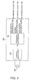
- Fig. 2 shows a block diagram according to the invention in which the clock generator generating the non-spread spectrum clock and the clock generator generating the spread spectrum clock are constructed using the same IC.
- the three clock generators shown in Fig. 1 are constructed using the same IC.
- This IC 130 is provided with a crystal oscillator 132 and a frequency synthesizer 134 and is connected to a crystal resonator 136 outside.
- the crystal oscillator 132 employs the crystal resonator 136 as the inductive impedance to generate a signal having a constant frequency, from which signal the frequency synthesizer 134 generates each of two non-spread spectrum clocks having different frequencies and a spread spectrum clock undergoing the spread spectrum with a predetermined spread amount, whereby the memory clock 122, the system clock 126, and the display clock 124 are obtained.
- the clock generator that generates the non-spread spectrum clock and the clock generator that generates the spread spectrum clock so that they share the same IC that contributes curtailment of the number of parts and the area occupied on the circuit boards.
- the three clock generators indicated in Fig. 1 are constructed using the same IC.
Landscapes
- Engineering & Computer Science (AREA)
- Physics & Mathematics (AREA)
- Computer Hardware Design (AREA)
- General Physics & Mathematics (AREA)
- Theoretical Computer Science (AREA)
- Multimedia (AREA)
- Chemical & Material Sciences (AREA)
- Crystallography & Structural Chemistry (AREA)
- Liquid Crystal Display Device Control (AREA)
- Control Of Indicators Other Than Cathode Ray Tubes (AREA)
- Shielding Devices Or Components To Electric Or Magnetic Fields (AREA)
- Synchronisation In Digital Transmission Systems (AREA)
Applications Claiming Priority (2)
| Application Number | Priority Date | Filing Date | Title |
|---|---|---|---|
| JP2002177517A JP2004023556A (ja) | 2002-06-18 | 2002-06-18 | 電子機器 |
| JP2002177517 | 2002-06-18 |
Publications (3)
| Publication Number | Publication Date |
|---|---|
| EP1376531A2 EP1376531A2 (en) | 2004-01-02 |
| EP1376531A3 EP1376531A3 (en) | 2005-06-08 |
| EP1376531B1 true EP1376531B1 (en) | 2012-06-13 |
Family
ID=29717473
Family Applications (1)
| Application Number | Title | Priority Date | Filing Date |
|---|---|---|---|
| EP20030253780 Expired - Lifetime EP1376531B1 (en) | 2002-06-18 | 2003-06-16 | Electronic apparatus with reduced electromagnetic interference noise |
Country Status (6)
| Country | Link |
|---|---|
| US (1) | US7224349B2 (https=) |
| EP (1) | EP1376531B1 (https=) |
| JP (1) | JP2004023556A (https=) |
| KR (1) | KR20040002586A (https=) |
| CN (2) | CN1469571A (https=) |
| TW (1) | TW586344B (https=) |
Families Citing this family (6)
| Publication number | Priority date | Publication date | Assignee | Title |
|---|---|---|---|---|
| US7809973B2 (en) * | 2005-11-16 | 2010-10-05 | Cypress Semiconductor Corporation | Spread spectrum clock for USB |
| US8035630B2 (en) | 2006-10-13 | 2011-10-11 | Seiko Epson Corporation | USB image transmission system and device |
| US8055003B2 (en) | 2008-04-01 | 2011-11-08 | Apple Inc. | Acoustic systems for electronic devices |
| TWI460572B (zh) | 2009-12-04 | 2014-11-11 | Via Tech Inc | 時脈產生器以及通用串列匯流排模組 |
| US8892184B2 (en) | 2010-10-18 | 2014-11-18 | Siemens Medical Solutions Usa, Inc. | Systems and methods for reducing interference in a dual modality imaging system |
| KR20150019884A (ko) * | 2013-08-16 | 2015-02-25 | 삼성전자주식회사 | 디스플레이 구동 회로 및 디스플레이 장치 |
Citations (3)
| Publication number | Priority date | Publication date | Assignee | Title |
|---|---|---|---|---|
| GB2349006A (en) * | 1999-04-12 | 2000-10-18 | Lg Philips Lcd Co Ltd | Data interface device |
| GB2352575A (en) * | 1999-04-06 | 2001-01-31 | Lg Philips Lcd Co Ltd | Liquid crystal monitor drive apparatus with reduced vulnerability to EMI emissions |
| JP2002091603A (ja) * | 2000-09-20 | 2002-03-29 | Sharp Corp | クロック発生回路を内蔵する集積回路 |
Family Cites Families (37)
| Publication number | Priority date | Publication date | Assignee | Title |
|---|---|---|---|---|
| EP0163313A3 (en) | 1984-05-30 | 1986-10-01 | Tektronix, Inc. | Method and apparatus for spectral dispersion of the radiated energy from a digital system |
| US4847603A (en) * | 1986-05-01 | 1989-07-11 | Blanchard Clark E | Automatic closed loop scaling and drift correcting system and method particularly for aircraft head up displays |
| US4740792A (en) * | 1986-08-27 | 1988-04-26 | Hughes Aircraft Company | Vehicle location system |
| US5631920A (en) | 1993-11-29 | 1997-05-20 | Lexmark International, Inc. | Spread spectrum clock generator |
| US5488627A (en) * | 1993-11-29 | 1996-01-30 | Lexmark International, Inc. | Spread spectrum clock generator and associated method |
| US5640002A (en) * | 1995-08-15 | 1997-06-17 | Ruppert; Jonathan Paul | Portable RF ID tag and barcode reader |
| US6020939A (en) | 1996-01-19 | 2000-02-01 | Sun Microsystems, Inc. | Method and apparatus for reducing electromagnetic interference radiated by cathode ray tube displays |
| US5757338A (en) * | 1996-08-21 | 1998-05-26 | Neomagic Corp. | EMI reduction for a flat-panel display controller using horizontal-line based spread spectrum |
| US5769032A (en) * | 1997-02-03 | 1998-06-23 | Yarnall, Sr.; Robert G. | Method and apparatus for confining animals and/or humans using spread spectrum signals |
| US5999561A (en) * | 1997-05-20 | 1999-12-07 | Sanconix, Inc. | Direct sequence spread spectrum method, computer-based product, apparatus and system tolerant to frequency reference offset |
| US6169889B1 (en) * | 1997-08-04 | 2001-01-02 | Motorola | Method and electronic device using random pulse characteristics in digital signals |
| JPH1173725A (ja) * | 1997-08-29 | 1999-03-16 | Sony Corp | 情報信号記録再生システム、情報記録装置、情報信号再生装置および情報信号記録再生方法 |
| EP0968580B1 (en) * | 1998-01-20 | 2006-06-21 | Silicon Image, Inc. | Spread spectrum phase modulation for suppression of electromagnetic interference in parallel data channels |
| JP4034440B2 (ja) | 1998-10-16 | 2008-01-16 | オリンパス株式会社 | 映像機器 |
| JP3363808B2 (ja) * | 1998-11-24 | 2003-01-08 | 富士通株式会社 | シミュレーション装置及び方法並びにプログラム記録媒体 |
| JP2000216667A (ja) | 1999-01-25 | 2000-08-04 | Hitachi Ltd | クロック発振回路 |
| US6687319B1 (en) * | 1999-02-04 | 2004-02-03 | Rambus Inc. | Spread spectrum clocking of digital signals |
| JP2000252817A (ja) | 1999-03-03 | 2000-09-14 | Kawasaki Steel Corp | Pll回路 |
| US6693511B1 (en) * | 1999-09-24 | 2004-02-17 | Ge Interlogix, Inc. | System and method for communicating with dormant radio frequency identification tags |
| US6396438B1 (en) * | 1999-09-24 | 2002-05-28 | Slc Technologies | System and method for locating radio frequency identification tags using three-phase antenna |
| US6876339B2 (en) * | 1999-12-27 | 2005-04-05 | Semiconductor Energy Laboratory Co., Ltd. | Semiconductor device and driving method thereof |
| JP2001191585A (ja) | 2000-01-13 | 2001-07-17 | Ricoh Co Ltd | 電子機器、画像形成装置、複写機およびファクシミリ装置 |
| US6580432B1 (en) * | 2000-01-14 | 2003-06-17 | Ati International Srl | Spread spectrum FIFO and method for storing data for multiple display types |
| US6562001B2 (en) * | 2000-01-21 | 2003-05-13 | Medtronic Minimed, Inc. | Microprocessor controlled ambulatory medical apparatus with hand held communication device |
| US6366174B1 (en) * | 2000-02-21 | 2002-04-02 | Lexmark International, Inc. | Method and apparatus for providing a clock generation circuit for digitally controlled frequency or spread spectrum clocking |
| US6643317B1 (en) * | 2000-02-25 | 2003-11-04 | Electronics For Imaging, Inc. | Digital spread spectrum circuit |
| JP4694670B2 (ja) | 2000-03-31 | 2011-06-08 | 株式会社日立製作所 | プラズマ表示装置 |
| KR100706742B1 (ko) * | 2000-07-18 | 2007-04-11 | 삼성전자주식회사 | 평판 디스플레이 장치 |
| US6493275B2 (en) * | 2000-08-07 | 2002-12-10 | Matsushita Electric Industrial Co., Ltd. | Semiconductor integrated circuit device and electronic equipment |
| KR100471054B1 (ko) * | 2000-11-18 | 2005-03-07 | 삼성전자주식회사 | 컴퓨터 시스템 및 그의 화상처리방법 |
| JP2002158839A (ja) | 2000-11-20 | 2002-05-31 | Ricoh Co Ltd | 画像読取装置 |
| JP3997069B2 (ja) * | 2001-10-03 | 2007-10-24 | キヤノン株式会社 | 周波数拡散発振器を有する集積回路装置及び該装置を有するインクジェット記録装置 |
| WO2003036607A1 (en) * | 2001-10-25 | 2003-05-01 | Fujitsu Limited | Display control device |
| JP3591503B2 (ja) * | 2001-11-08 | 2004-11-24 | セイコーエプソン株式会社 | 周波数拡散されたクロックを基準に動作し、入力画像信号を処理する画像処理装置 |
| US7346099B2 (en) * | 2002-01-03 | 2008-03-18 | Intel Corporation | Network fabric physical layer |
| US7305020B2 (en) * | 2002-02-04 | 2007-12-04 | Vizionware, Inc. | Method and system of reducing electromagnetic interference emissions |
| US6982707B2 (en) * | 2002-03-14 | 2006-01-03 | Genesis Microchip Inc. | Method and apparatus utilizing direct digital synthesizer and spread spectrum techniques for reducing EMI in digital display devices |
-
2002
- 2002-06-18 JP JP2002177517A patent/JP2004023556A/ja active Pending
-
2003
- 2003-06-10 US US10/457,767 patent/US7224349B2/en not_active Expired - Fee Related
- 2003-06-12 TW TW92116004A patent/TW586344B/zh not_active IP Right Cessation
- 2003-06-16 EP EP20030253780 patent/EP1376531B1/en not_active Expired - Lifetime
- 2003-06-17 KR KR1020030038951A patent/KR20040002586A/ko not_active Ceased
- 2003-06-17 CN CNA031410472A patent/CN1469571A/zh active Pending
- 2003-06-18 CN CNU032646437U patent/CN2678260Y/zh not_active Expired - Lifetime
Patent Citations (3)
| Publication number | Priority date | Publication date | Assignee | Title |
|---|---|---|---|---|
| GB2352575A (en) * | 1999-04-06 | 2001-01-31 | Lg Philips Lcd Co Ltd | Liquid crystal monitor drive apparatus with reduced vulnerability to EMI emissions |
| GB2349006A (en) * | 1999-04-12 | 2000-10-18 | Lg Philips Lcd Co Ltd | Data interface device |
| JP2002091603A (ja) * | 2000-09-20 | 2002-03-29 | Sharp Corp | クロック発生回路を内蔵する集積回路 |
Non-Patent Citations (1)
| Title |
|---|
| GARDINER S. ET AL: "AN INTRODUCTION TO SPREAD SPECTRUM CLOCK GENERATION FOR EMI REDUCTION", ELECTRONIC ENGINEERING, vol. 71, no. 867, 1 April 1999 (1999-04-01), MORGAN-GRAMPIAN LTD. LONDON, GB, pages 75,77 - 79,81, XP000907996 * |
Also Published As
| Publication number | Publication date |
|---|---|
| US20040041775A1 (en) | 2004-03-04 |
| CN2678260Y (zh) | 2005-02-09 |
| EP1376531A2 (en) | 2004-01-02 |
| KR20040002586A (ko) | 2004-01-07 |
| TW586344B (en) | 2004-05-01 |
| TW200401604A (en) | 2004-01-16 |
| CN1469571A (zh) | 2004-01-21 |
| EP1376531A3 (en) | 2005-06-08 |
| US7224349B2 (en) | 2007-05-29 |
| JP2004023556A (ja) | 2004-01-22 |
Similar Documents
| Publication | Publication Date | Title |
|---|---|---|
| US7446732B2 (en) | Display control device | |
| US8320428B1 (en) | Spread spectrum clock generator with controlled delay elements | |
| JP2889113B2 (ja) | 遅延発生装置、デ−タ処理システム及びデ−タ伝送システム | |
| US6917449B2 (en) | Image processing apparatus and method of the same, and storage medium | |
| US6982707B2 (en) | Method and apparatus utilizing direct digital synthesizer and spread spectrum techniques for reducing EMI in digital display devices | |
| EP1376531B1 (en) | Electronic apparatus with reduced electromagnetic interference noise | |
| EP1311131B1 (en) | Image processing apparatus working in response to frequency diffused clock as reference to process input image signals | |
| US6628254B1 (en) | Display device and interface circuit for the display device | |
| US7295048B2 (en) | Method and apparatus for generating spread spectrum clock signals having harmonic emission suppressions | |
| US11557240B2 (en) | Driving controller, display apparatus having the same and method of driving the same | |
| JP4490837B2 (ja) | 携帯端末 | |
| JP3097688B2 (ja) | 画像出力装置用コントローラ、画像出力装置、画像出力装置の制御方法 | |
| JP2001111745A (ja) | ファクシミリ装置 | |
| JP2007043554A (ja) | 電子回路装置のemi対策方法及び回路 | |
| KR20030058732A (ko) | 액정 표시 장치의 구동 회로 | |
| Kim et al. | Chip level EMI approach for LCD TV panels | |
| KR20130060805A (ko) | 화상형성장치, 신호 출력 장치 및 신호 출력 방법 | |
| JP2006167983A (ja) | プリンタコントローラ | |
| JPH11174406A (ja) | 集積回路およびそれを用いた液晶表示装置 | |
| JP2002343876A (ja) | 半導体集積回路 | |
| JP2002189527A (ja) | 放射ノイズ低減装置及び放射ノイズ低減方法 | |
| KR20050016306A (ko) | 디지털 디스플레이 장치에서 emi를 감소하기 위해직접적 디지털 신서사이저 및 전개 스펙트럼 기술을이용하는 방법 및 장치 | |
| JPS63267992A (ja) | 情報処理装置 |
Legal Events
| Date | Code | Title | Description |
|---|---|---|---|
| PUAI | Public reference made under article 153(3) epc to a published international application that has entered the european phase |
Free format text: ORIGINAL CODE: 0009012 |
|
| AK | Designated contracting states |
Kind code of ref document: A2 Designated state(s): AT BE BG CH CY CZ DE DK EE ES FI FR GB GR HU IE IT LI LU MC NL PT RO SE SI SK TR |
|
| AX | Request for extension of the european patent |
Extension state: AL LT LV MK |
|
| PUAL | Search report despatched |
Free format text: ORIGINAL CODE: 0009013 |
|
| AK | Designated contracting states |
Kind code of ref document: A3 Designated state(s): AT BE BG CH CY CZ DE DK EE ES FI FR GB GR HU IE IT LI LU MC NL PT RO SE SI SK TR |
|
| AX | Request for extension of the european patent |
Extension state: AL LT LV MK |
|
| RIC1 | Information provided on ipc code assigned before grant |
Ipc: 7H 03K 3/84 B Ipc: 7G 09G 3/36 A Ipc: 7H 04B 1/713 B Ipc: 7G 09G 5/18 B |
|
| 17P | Request for examination filed |
Effective date: 20051108 |
|
| AKX | Designation fees paid |
Designated state(s): DE FR GB |
|
| GRAP | Despatch of communication of intention to grant a patent |
Free format text: ORIGINAL CODE: EPIDOSNIGR1 |
|
| RIN1 | Information on inventor provided before grant (corrected) |
Inventor name: IRIE, MICHIO |
|
| GRAS | Grant fee paid |
Free format text: ORIGINAL CODE: EPIDOSNIGR3 |
|
| GRAA | (expected) grant |
Free format text: ORIGINAL CODE: 0009210 |
|
| AK | Designated contracting states |
Kind code of ref document: B1 Designated state(s): DE FR GB |
|
| REG | Reference to a national code |
Ref country code: GB Ref legal event code: FG4D |
|
| REG | Reference to a national code |
Ref country code: DE Ref legal event code: R096 Ref document number: 60341237 Country of ref document: DE Effective date: 20120809 |
|
| PLBE | No opposition filed within time limit |
Free format text: ORIGINAL CODE: 0009261 |
|
| STAA | Information on the status of an ep patent application or granted ep patent |
Free format text: STATUS: NO OPPOSITION FILED WITHIN TIME LIMIT |
|
| 26N | No opposition filed |
Effective date: 20130314 |
|
| REG | Reference to a national code |
Ref country code: DE Ref legal event code: R097 Ref document number: 60341237 Country of ref document: DE Effective date: 20130314 |
|
| REG | Reference to a national code |
Ref country code: FR Ref legal event code: PLFP Year of fee payment: 14 |
|
| REG | Reference to a national code |
Ref country code: FR Ref legal event code: PLFP Year of fee payment: 15 |
|
| PGFP | Annual fee paid to national office [announced via postgrant information from national office to epo] |
Ref country code: DE Payment date: 20170613 Year of fee payment: 15 Ref country code: FR Payment date: 20170511 Year of fee payment: 15 Ref country code: GB Payment date: 20170614 Year of fee payment: 15 |
|
| REG | Reference to a national code |
Ref country code: DE Ref legal event code: R119 Ref document number: 60341237 Country of ref document: DE |
|
| GBPC | Gb: european patent ceased through non-payment of renewal fee |
Effective date: 20180616 |
|
| PG25 | Lapsed in a contracting state [announced via postgrant information from national office to epo] |
Ref country code: DE Free format text: LAPSE BECAUSE OF NON-PAYMENT OF DUE FEES Effective date: 20190101 Ref country code: FR Free format text: LAPSE BECAUSE OF NON-PAYMENT OF DUE FEES Effective date: 20180630 Ref country code: GB Free format text: LAPSE BECAUSE OF NON-PAYMENT OF DUE FEES Effective date: 20180616 |