EP1375804A2 - In den Boden einbaubare, justierbare Führungsschiene mit mehreren Konfigurationen, für Schiebeflügel mit eingebautem Wassersammlungs- und Feuchtigkeitsentfernungssystem - Google Patents
In den Boden einbaubare, justierbare Führungsschiene mit mehreren Konfigurationen, für Schiebeflügel mit eingebautem Wassersammlungs- und Feuchtigkeitsentfernungssystem Download PDFInfo
- Publication number
- EP1375804A2 EP1375804A2 EP03253596A EP03253596A EP1375804A2 EP 1375804 A2 EP1375804 A2 EP 1375804A2 EP 03253596 A EP03253596 A EP 03253596A EP 03253596 A EP03253596 A EP 03253596A EP 1375804 A2 EP1375804 A2 EP 1375804A2
- Authority
- EP
- European Patent Office
- Prior art keywords
- track
- built
- floor
- channel
- moisture
- Prior art date
- Legal status (The legal status is an assumption and is not a legal conclusion. Google has not performed a legal analysis and makes no representation as to the accuracy of the status listed.)
- Granted
Links
Images


Classifications
-
- E—FIXED CONSTRUCTIONS
- E06—DOORS, WINDOWS, SHUTTERS, OR ROLLER BLINDS IN GENERAL; LADDERS
- E06B—FIXED OR MOVABLE CLOSURES FOR OPENINGS IN BUILDINGS, VEHICLES, FENCES OR LIKE ENCLOSURES IN GENERAL, e.g. DOORS, WINDOWS, BLINDS, GATES
- E06B7/00—Special arrangements or measures in connection with doors or windows
- E06B7/14—Measures for draining-off condensed water or water leaking-in frame members for draining off condensation water, throats at the bottom of a sash
-
- E—FIXED CONSTRUCTIONS
- E05—LOCKS; KEYS; WINDOW OR DOOR FITTINGS; SAFES
- E05D—HINGES OR SUSPENSION DEVICES FOR DOORS, WINDOWS OR WINGS
- E05D15/00—Suspension arrangements for wings
- E05D15/06—Suspension arrangements for wings for wings sliding horizontally more or less in their own plane
- E05D15/0621—Details, e.g. suspension or supporting guides
- E05D15/066—Details, e.g. suspension or supporting guides for wings supported at the bottom
- E05D15/0686—Tracks
-
- E—FIXED CONSTRUCTIONS
- E06—DOORS, WINDOWS, SHUTTERS, OR ROLLER BLINDS IN GENERAL; LADDERS
- E06B—FIXED OR MOVABLE CLOSURES FOR OPENINGS IN BUILDINGS, VEHICLES, FENCES OR LIKE ENCLOSURES IN GENERAL, e.g. DOORS, WINDOWS, BLINDS, GATES
- E06B3/00—Window sashes, door leaves, or like elements for closing wall or like openings; Layout of fixed or moving closures, e.g. windows in wall or like openings; Features of rigidly-mounted outer frames relating to the mounting of wing frames
- E06B3/32—Arrangements of wings characterised by the manner of movement; Arrangements of movable wings in openings; Features of wings or frames relating solely to the manner of movement of the wing
- E06B3/34—Arrangements of wings characterised by the manner of movement; Arrangements of movable wings in openings; Features of wings or frames relating solely to the manner of movement of the wing with only one kind of movement
- E06B3/42—Sliding wings; Details of frames with respect to guiding
- E06B3/46—Horizontally-sliding wings
- E06B3/4636—Horizontally-sliding wings for doors
Definitions
- This invention relates to the field of sliding door assembly and installation. More particularly, the invention pertains to a novel floor support system for sliding glass or non-glass panels, that act as doors or room dividers, and to a system for supporting them on a floor-level track including means for draining off water that accumulates on the floor or on either side of the door.
- a significant problem with these types of sliding panels occurs where one side of the panels faces outside the home or building toward the elements.
- Rain, sleet or snow hitting the glass and panel is drawn downward by gravity so that it puddles at the bottom of the panel and, when in great enough quantities, spills over onto the tracks upon which the panels are mounted for sliding movement.
- the floor on one side of the track is slanted such that rain or melted snow runs toward the track.
- problems develop because of the many directions the moisture may flow. For instance, it sometimes flows under the panel and into a room wetting carpets and rugs that thereafter become stained, crispy, or develop an organic growth that causes bad odors and attracts insects.
- the moisture sometimes flows outward from the panel and stains concrete or causes deterioration of cement and wood flooring, or corrodes the glue that holds down floor coverings such as linoleum, parquet, and vinyl squares.
- a preferred embodiment is an in-floor, adjustable, track assembly for sliding panels with a built-in weep system to collect and thereafter remove the moisture from the track area where, when installation is complete, the exposed surface of the track is minimal resulting in a smooth transition from interior to exterior. It is useful on single or multiple track systems in areas that are divided by the panels into an exterior or outside section and an interior or inside section. This system finds use where the tracks are mounted on a base, are single tracks or are in closely spaced-apart, parallel arrangement and extend upward from the base for engaging the undercarriage of at least two vertically-oriented panels in close arrangement.
- the invention provides for splash guards arranged parallel to and spaced slightly apart from one side of each track, preferably the interior area, and forming, with each track, a channel with the base, for collecting moisture from the floor.
- At least one collection pan is mounted under each channel, to collect moisture from the channel, and includes a tube or other means to draw off the moisture from the collection pan to a distant location.
- Preferably much of the invention is formed of extruded metal, such as aluminum, so that the cost of construction is minimized.
- the invention may be fully adjustable in vertical, as well as horizontal, directions so that it can be placed in new construction and installed in existing construction as well.
- Other parts are made preferably made of plastic and/or rubber so that the entire system is generally free from problems of corrosion even in the face of constant exposure to moisture.
- a preferred embodiment of this invention is an in-floor, adjustable, track assembly for sliding panels with a built-in weep system that will remove moisture that flows across the floor, and possibly across the track, or that trickles down the sliding panels to puddle at the bottom thereof.
- Another preferred aspect of the invention is a fully adjustable track assembly that may be adjusted to compensate for warpage, weakness, and misalignment of walls with floors to allow the panels to slide effortlessly over the track.
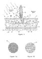
- Figure 1 shows the in-floor, adjustable, single configuration track assembly 1 for a sliding panel with a built-in weep system of this invention to comprise a narrow, elongated track 3 extending upward from a base 5, slightly above the top surface 7 of finished floor 9 for engaging the undercarriage wheels 13 of a panel 15 (wheels 13 and panel 15 are shown in phantom outline) and supporting panel 15 while it is in motion, such as in rectilinear motion, on track 3.
- track 3 is an upright, elongated, narrow-gauge metal plate forming an inverted "T" shape with base 5.
- Track 3 includes a shaped top surface with small, lateral undercuts 17 for smooth engagement with wheels 13, that extend downward from the bottom of panel 15.
- Panel 15 has a stout perimeter 19 of metal or wood construction, panel inserts of glass or wood, and generally is quite heavy. It is preferred that track 3 be extruded, such as from aluminum or other extrudable metal, in a single piece with base 5. Such extrusion further includes flanges 21, extending outward from both sides of base 5.
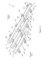
- Figure 3 shows an in-floor, adjustable, multiple configuration track assembly for a plurality of sliding panels 15 (not shown), each with a built-in weep system of this invention, and shows a plurality of narrow, elongated tracks 3 in closely spaced-apart, parallel arrangement, each track 3 extending upward from a separate base 5, for engaging and supporting the undercarriage of at least one panel on each track 3 while said panels are in motion, such as rectilinear motion, thereon.
- track top surface 17 protrudes or extends slightly above finished floor top surface 7 (see Figure 2) to form a slight barrier to transverse flow of water or moisture across track 3 from the exterior area to the interior area.
- an upright splash guard 25 is provided for each of narrow tracks 3, parallel to and spaced slightly apart therefrom a distance sufficient to capture moisture either dripping or running off panel 15, shown as drops 27, or running across finished floor top surface 7 and over the top of track 3 from the exterior area toward the interior area.
- Splash guard 25 forms, with each track 3 and base 5, a narrow channel 29 for collecting moisture from the bottom of each panel 15.
- moisture means rain, sleet, snow, and water splashed from swimming pools, hoses and the like. Moisture is shown as angled straight lines in the exterior area in Figure 2.
- track 3 and splash guard 25 are both upright, elongated, narrow-gauge plates and, together, form an inverted "T" shape with base 5.
- splash guard 25 terminates or “tops” at finished floor top surface 7 so that the entire assembly is at or below top surface 7, except for a slight upward protrusion of track top surface 17 and thus forms a very smooth, uninterrupted top floor surface.
- This configuration conforms to the requirements of the Americans with Disabilities Act (42 U.S.C ⁇ 12100 et sec.). Since splash guard 25 and track 3 together form a substantially inverted "T” with base 5, it is preferred that they all be extruded together in one monolithic piece from metal such as aluminum. If not possible, it is preferred that track 3 and base 5 be extruded as one piece and splash guard 21 installed, as shown, and soldered or otherwise rigidly mounted in base 5.
- a filter means 31 is located in said channel 29 for preventing the ingress of debris.
- filter means 31 may take the form of a strip of highly reticulated plastic foam 33 cut and inserted into channel 29.
- a piece of screen 37 may be cut and folded in a shape and slipped into channel 29. Not only do these means prevent the ingress of debris while also not interfering with the collection of moisture, they also are easily removed so that they can be renewed without significant cost or effort.
- At least one collection pan 39 is mounted under each channel 29 and is accessible through at least one aperture 41 formed in the bottom of channel 29, preferably at the bottom of channel 29 in base 5.
- Collection pan 39 collects moisture that runs down into channel 29.
- Collection pan 39 is preferably made from plastic, such as polyvinyl chloride, polyvinylidine chloride, polyethylene, and the like, and can be easily injection molded to reduce the cost of production.
- collection pan 39 comprises enclosed sidewalls 43, a closed bottom 45, and an open top cavity 49 formed therein.
- Second Walls 43 are attached through gaskets 51, along their top surfaces, to the bottom surface 53 of base 5 and cavity 49 is preferably arranged directly below aperture 41 to receive moisture as it drops from the panels into channel 29 and through filter means 31.
- An opening 55 preferably located in or near collection pan bottom 45 is provided and egress means 57, such as a hose or tube 61, is attached thereto to draw off the moisture from the bottom of said panels.
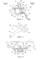
- each rail 63 includes a rail body 65, defined by a bottom surface 67 and a top surface 69.
- a pair of alignment clamps 73a and 73b are provided for each track, for assembly with rails 63 to fasten each track to each rail.
- the alignment between tracks 3 and rails 63 is orthogonal, i.e., each track is adjusted to be as close as possible to perpendicular from each rail.
- Each clamp 73a and 73b includes a bottom clamp surface 75, a portion 77 of which is shaped for overlapping contact with a curb 79a and 79b formed on track flanges 21 on both sides of track 3.
- a C-shaped groove 81 is formed in track support rail body 63 opening upward through a slot 83 formed in rail body top surface 69.
- An aperture 87 is formed in alignment clamps 73a and 73b for arrangement over upwardly opening C-shaped groove 81.
- clamps 73a and 73b are assembled with track 3 and track support rail 63 such that track 3 is overlaid rail 63 and clamps 73a and 73b placed on rail 63, one on each side thereof, with portion 77 of clamp bottom surface 75 overlaying flange 21 with slot 85 aligned with aperture 87.
- a threaded means 89 such as a flat headed bolt or machine screw 91, is inserted down through aperture 87, through slot 85, and into a bolt-capturing nut 93 located in C-shaped groove 81.
- Nut 93 is wider than slot 85 but smaller than the maximum internal width of C-shaped groove 81 so that it is captured in groove 81 yet is slightly moveable therein. It is preferred that the outside diameter of bolt 91 be made slightly less than the width of slot 85 to allow for some movement between bolt 91, track 3 and rail 63. This slight looseness allows track 3 and rail 63 to be adjusted horizontally in the floor on which track 3 will be mounted and further allows track 3 and rail 63 to be brought as close as possible to orthogonal arrangement during assembly.
- bolt 91 have a flat heat with conical sides, as shown in Figure 6, and aperture 87 in clamps 73a and 73b have a top chamfer to accept the flat bolt head so that the flat head of bolt 91 will lie flush with the top surface of alignment clamps 73a and 73b.
- a pair of upsets or curbs, 97a and 97b be formed in spaced-apart arrangement on track support rail top surface 69 that, together, form a wide, substantially "U"-shaped depression 99 in rail top surface 69.
- Alignment clamps 97a and 97b are preferably made just wide enough to fit into said depression 99 and aligned therein for assembly with track 3 and rail 63 to prevent the clamps from moving about when the assembly is subjected to the movement of panels 15 on tracks 3.
- a side mounting tab 101 is formed as an extension on the ends of track support rails 63.
- An adjustment/mounting slot 103 is formed in rail body 65, preferably at the center of C-shaped groove 81, and through the bottom of rail body 65.
- an elongated, slightly V-shaped indentation 105 is formed in the upper surface of the bottom surface of groove 81 and, preferably, along the center-line of rail bottom surface 67 for aiding in aligning a drill bit to drill through the bottom of rail body 65 in order to center the drill bit used in forming adjustment mounting slot 103.
- a first pair of threaded studs 109 is mounted in the cement sub-floor 111 or in the wood sub-floor or other support surface, in spaced-apart arrangement, a distance equal to the distance between adjusting/mounting slots 103 that are formed at each end of rail 63, and along an axis orthogonal to the axis of intended travel of the panels.
- Rail 63 is then set down on studs 109 and is shimmed to level.
- a first pair of bolt-capturing nuts 113 is then placed in threaded engagement on studs 109 and tightened down against that portion of rail body 65 at the bottom of C-shaped groove 81 and fastened into place to provide rigid support for the entire assembly.
- Tracks 3 are then placed on top of rails 63 and alignment clamps 73a and 73b are placed on rail top surface 69, one on each side of track 3 and partially overlapping onto track flanges 21.
- Flat-headed bolts or machine screws 91 are then inserted into clamp aperture 87 and passed down into threaded receipt in bolt-capturing nuts 93 that are first slipped inside C-shaped groove 81, in rail body 65. Nuts 93 are then tightened down to rigidify the assembly.
- tracks 3 be orthogonal or perpendicular to rails 63 when the full assembly is rigidified.
- collection pans 39, already mounted under rails 63 are connected to hoses 61 to be passed through holes in the sub-floor, preferably to an outside vent for removing the collected moisture from tracks 3.
- a trap 115 may be located transversely between at least two adjacent tracks 3 that are in closely spaced-apart, passing arrangement, in order to collect the moisture that impacts the ends of panels 15 and runs down toward the underlying tracks 3.
- Panel perimeters 19 often are wide in order to support heavy panel inserts, such as glass panes and wood sheeting. This transverse thickness of the perimeter presents a rather broad surface for moisture to impact and trickle downward.
- Trap 115 is shown in Figure 8 to comprise a pair of closely spaced-apart, parallel walls 117 and 119 and a closed base 123 forms an open top U-shaped duct 125 therebetween.
- a pair of outwardly directed positioning slots 127a and 127b are formed in base 123 for sliding over inwardly-facing flanges 21 on the two adjacent track bases 5.
- Mounted along the top of wall 117 is a pliable seal 129 for the purpose of contacting panel undercarriage 13 to seal trap 115 against leakage of moisture entering duct 125.
- Filter means 31, as previously disclosed, may also be inserted in duct 125 to prevent the ingress of debris along with the entrance of moisture.
- At least one collection pan 39 is mounted under each transverse trap 115 and is accessible through an aperture 87, located at the bottom of duct 125 to pass moisture from duct 129 to an egress means 57, such as hose 61, as previously disclosed.
- sub-floor 111 is thereafter encased, about its sides and underneath, with additional sub-floor 131, in preparation of the laying of final or finished floor 9 that closes off a view of the invention except for a small upper portion of tracks 3 and the very top of splash guard 25.
- splash guard 25 and narrow channel 29 may be located on the exterior area of the assembly, however, it is preferred that they be located on the interior area of the assembly.
Landscapes
- Engineering & Computer Science (AREA)
- Civil Engineering (AREA)
- Structural Engineering (AREA)
- Mechanical Engineering (AREA)
- Floor Finish (AREA)
- Magnetic Bearings And Hydrostatic Bearings (AREA)
- Support Devices For Sliding Doors (AREA)
- Machines For Laying And Maintaining Railways (AREA)
- Supports For Pipes And Cables (AREA)
- Vehicle Cleaning, Maintenance, Repair, Refitting, And Outriggers (AREA)
Applications Claiming Priority (2)
| Application Number | Priority Date | Filing Date | Title |
|---|---|---|---|
| US185942 | 1998-11-04 | ||
| US10/185,942 US6792651B2 (en) | 2002-06-27 | 2002-06-27 | In-floor, adjustable, multiple-configuration track assembly for sliding panels with built-in weep system |
Publications (3)
| Publication Number | Publication Date |
|---|---|
| EP1375804A2 true EP1375804A2 (de) | 2004-01-02 |
| EP1375804A3 EP1375804A3 (de) | 2006-09-27 |
| EP1375804B1 EP1375804B1 (de) | 2009-11-04 |
Family
ID=29718016
Family Applications (1)
| Application Number | Title | Priority Date | Filing Date |
|---|---|---|---|
| EP03253596A Expired - Lifetime EP1375804B1 (de) | 2002-06-27 | 2003-06-06 | In den Boden einbaubare, justierbare Führungsschiene mit mehreren Konfigurationen, für Schiebeflügel mit eingebautem Wassersammlungs- und Feuchtigkeitsentfernungssystem |
Country Status (5)
| Country | Link |
|---|---|
| US (3) | US6792651B2 (de) |
| EP (1) | EP1375804B1 (de) |
| AT (1) | ATE447654T1 (de) |
| CA (1) | CA2428220C (de) |
| DE (1) | DE60329890D1 (de) |
Cited By (21)
| Publication number | Priority date | Publication date | Assignee | Title |
|---|---|---|---|---|
| EP1726765A1 (de) * | 2005-05-10 | 2006-11-29 | Reynaers Aluminium, naamloze vennootschap | Schiebetür oder Schiebefenster mit verbesserter Drainage |
| US7246411B2 (en) | 2003-12-19 | 2007-07-24 | Jeld-Wen, Inc. | Methods and systems for sliding windows and doors |
| CN100356029C (zh) * | 2005-01-31 | 2007-12-19 | 经阁铝业科技股份有限公司 | 提升推拉门(窗) |
| ITBL20110008A1 (it) * | 2011-10-19 | 2013-04-20 | Gap Italia S R L | Sistema di fissaggio ad innesto dei binari superiore ed inferiore, particolarmente per porte scorrevoli di mobili. |
| CN104806136A (zh) * | 2015-03-31 | 2015-07-29 | 成都聚智工业设计有限公司 | 门窗排水结构 |
| US9097059B1 (en) | 2014-05-01 | 2015-08-04 | Andersen Corporation | Draining sill and frame assembly incorporating the same |
| CN105593448A (zh) * | 2014-08-30 | 2016-05-18 | 创新建筑科技公司 | 地板镶板和镶板轨道之间的界面 |
| US10145103B2 (en) | 2010-06-08 | 2018-12-04 | Innovative Building Technologies, Llc | Premanufactured structures for constructing buildings |
| US10190309B2 (en) | 2010-06-08 | 2019-01-29 | Innovative Building Technologies, Llc | Slab construction system and method for constructing multi-story buildings using pre-manufactured structures |
| US10260250B2 (en) | 2014-08-30 | 2019-04-16 | Innovative Building Technologies, Llc | Diaphragm to lateral support coupling in a structure |
| US10323428B2 (en) | 2017-05-12 | 2019-06-18 | Innovative Building Technologies, Llc | Sequence for constructing a building from prefabricated components |
| US10329764B2 (en) | 2014-08-30 | 2019-06-25 | Innovative Building Technologies, Llc | Prefabricated demising and end walls |
| US10364572B2 (en) | 2014-08-30 | 2019-07-30 | Innovative Building Technologies, Llc | Prefabricated wall panel for utility installation |
| US10487493B2 (en) | 2017-05-12 | 2019-11-26 | Innovative Building Technologies, Llc | Building design and construction using prefabricated components |
| US10508442B2 (en) | 2016-03-07 | 2019-12-17 | Innovative Building Technologies, Llc | Floor and ceiling panel for slab-free floor system of a building |
| US10676923B2 (en) | 2016-03-07 | 2020-06-09 | Innovative Building Technologies, Llc | Waterproofing assemblies and prefabricated wall panels including the same |
| US10724228B2 (en) | 2017-05-12 | 2020-07-28 | Innovative Building Technologies, Llc | Building assemblies and methods for constructing a building using pre-assembled floor-ceiling panels and walls |
| US10900224B2 (en) | 2016-03-07 | 2021-01-26 | Innovative Building Technologies, Llc | Prefabricated demising wall with external conduit engagement features |
| US10961710B2 (en) | 2016-03-07 | 2021-03-30 | Innovative Building Technologies, Llc | Pre-assembled wall panel for utility installation |
| US11054148B2 (en) | 2014-08-30 | 2021-07-06 | Innovative Building Technologies, Llc | Heated floor and ceiling panel with a corrugated layer for modular use in buildings |
| US11098475B2 (en) | 2017-05-12 | 2021-08-24 | Innovative Building Technologies, Llc | Building system with a diaphragm provided by pre-fabricated floor panels |
Families Citing this family (24)
| Publication number | Priority date | Publication date | Assignee | Title |
|---|---|---|---|---|
| US20070151165A1 (en) * | 2006-01-03 | 2007-07-05 | Al Brendel | Door sill restrictor |
| US9458656B2 (en) | 2007-06-13 | 2016-10-04 | Andersen Corporation | Internally power slider with high torque drive system |
| US8381445B2 (en) | 2008-06-17 | 2013-02-26 | John B. Higman and Valorie J. Higman | Automatically sealing multi panel sliding door assembly |
| US8321551B2 (en) * | 2010-02-02 | 2012-11-27 | Symantec Corporation | Using aggregated DNS information originating from multiple sources to detect anomalous DNS name resolutions |
| US8336268B2 (en) * | 2010-02-02 | 2012-12-25 | Delaquis Daniel N J | Floor drainage system for a building and assembly therefor |
| US9217277B2 (en) | 2010-10-25 | 2015-12-22 | John B. Higman and Valorie J. Higman | Door drainage system |
| US9611652B2 (en) | 2011-02-25 | 2017-04-04 | Dustin M. M. Haddock | Mounting device for building surfaces having elongated mounting slot |
| US8561355B2 (en) * | 2011-05-10 | 2013-10-22 | Mark Canavarro | System for extending the height of cubicle walls |
| ES2529770T3 (es) * | 2011-05-20 | 2015-02-25 | Orchidées Constructions S.A. | Bastidor para paredes deslizantes |
| US8490349B2 (en) | 2011-05-27 | 2013-07-23 | Jeffrey Lutzner | In-floor track assembly for sliding panels with built-in drainage system |
| WO2013101597A1 (en) | 2011-12-29 | 2013-07-04 | Haddock Dustin M M | Mounting device for nail strip panels |
| US20170183896A1 (en) * | 2015-08-12 | 2017-06-29 | Design Synthesis Inc. | Drain track devices, assemblies and systems |
| US10443896B2 (en) | 2016-07-29 | 2019-10-15 | Rmh Tech Llc | Trapezoidal rib mounting bracket with flexible legs |
| US10640980B2 (en) | 2016-10-31 | 2020-05-05 | Rmh Tech Llc | Metal panel electrical bonding clip |
| US10851572B1 (en) | 2016-12-14 | 2020-12-01 | Andersen Corporation | Height compensating sliding fenestration systems and methods |
| US10422173B1 (en) | 2017-01-06 | 2019-09-24 | Andersen Corporation | Interlock assemblies for fenestration systems and methods |
| US11774143B2 (en) | 2017-10-09 | 2023-10-03 | Rmh Tech Llc | Rail assembly with invertible side-mount adapter for direct and indirect mounting applications |
| CR20220133A (es) | 2018-03-21 | 2022-05-23 | Rmh Tech Llc | Ensamble de montaje de modulo pv con acomodo de fijación y montaje vertical (divisional 2020-0491) |
| CN108952403A (zh) * | 2018-08-25 | 2018-12-07 | 广东炬森五金精密制造有限公司 | 一种内吸式平趟门下导轨板安装结构 |
| EP3894760A4 (de) | 2018-12-14 | 2022-09-07 | RMH Tech LLC | Montagevorrichtung für nagelbandplatten |
| CN110409963B (zh) * | 2019-08-02 | 2020-12-01 | 江西金百成五金制品有限公司 | 一种通过推送窗户移动产生气压清灰的推送窗户轨道 |
| WO2021188442A1 (en) | 2020-03-16 | 2021-09-23 | Rmh Tech Llc | Mounting device for a metal roof |
| US11041310B1 (en) | 2020-03-17 | 2021-06-22 | Rmh Tech Llc | Mounting device for controlling uplift of a metal roof |
| CN111425093B (zh) * | 2020-03-17 | 2021-09-07 | 老肯医疗科技股份有限公司 | 一种灭菌舱门用组合导轨及其使用方法 |
Citations (5)
| Publication number | Priority date | Publication date | Assignee | Title |
|---|---|---|---|---|
| GB824580A (en) * | 1957-08-28 | 1959-12-02 | Quicktho 1928 Ltd | Improvements in or relating to horizontal sliding windows |
| GB1063810A (en) * | 1964-12-08 | 1967-03-30 | Denis Edward Barnes | Improvements in sliding windows |
| FR2653817A1 (fr) * | 1989-10-27 | 1991-05-03 | Krieg & Zivy | Rail bas pour porte coulissante, notamment pour placard. |
| JPH05332068A (ja) * | 1992-06-03 | 1993-12-14 | Sekisui Chem Co Ltd | 引き戸 |
| JPH0828144A (ja) * | 1994-07-20 | 1996-01-30 | Sumitomo Forestry Co Ltd | 排水構造 |
Family Cites Families (35)
| Publication number | Priority date | Publication date | Assignee | Title |
|---|---|---|---|---|
| US1606073A (en) * | 1926-11-09 | hebberd | ||
| US204006A (en) * | 1878-05-21 | Improvement in portable railroad-tracks | ||
| US1408134A (en) * | 1921-09-08 | 1922-02-28 | Walter T O'donnell | Track drain |
| US3938621A (en) * | 1973-06-06 | 1976-02-17 | Rudolph Hafner | Vehicle servicing system |
| GB1513352A (en) * | 1975-04-17 | 1978-06-07 | Baus H | Lower guide member for partitions suitable for use in a wet-chamber |
| US4193544A (en) * | 1975-06-30 | 1980-03-18 | Kins Developments Limited | Rail clip assemblies |
| AU1856276A (en) * | 1975-10-27 | 1978-04-20 | Clive Investments Pty Ltd | Sill for doors and windows |
| US4010896A (en) * | 1976-03-25 | 1977-03-08 | Stockton William N | Modular liquid collection system for railroad roadbeds |
| US4208755A (en) * | 1979-02-05 | 1980-06-24 | Shepherd L Clay | Track wiper for sliding shower door assembly |
| US4358863A (en) * | 1979-11-26 | 1982-11-16 | Jacobsen Ralph E | Shower enclosure |
| US4572431A (en) * | 1981-06-22 | 1986-02-25 | Penta Construction Corp. | Rail fastener assembly |
| US4635846A (en) * | 1985-05-20 | 1987-01-13 | San Francisco Bay Area Rapid Transit District | Insulative protective device for rail fastener |
| DE3600133C1 (en) * | 1986-01-04 | 1987-01-29 | Ludwig Pfeifer | Shower cubicle |
| US4691487A (en) * | 1986-07-31 | 1987-09-08 | Gerald Kessler | Drain tube for windows |
| CA2059505A1 (en) * | 1991-01-17 | 1992-07-18 | Thomas J. Heppner | Sliding door sill construction |
| US5135165A (en) * | 1991-05-08 | 1992-08-04 | Gantrex Limited | Device for aligning and clamping a rail |
| US5136814A (en) * | 1991-05-09 | 1992-08-11 | Headrick Management Corporation | Draining door sill assembly with adjustable threshold cap |
| JPH04336191A (ja) * | 1991-05-14 | 1992-11-24 | Sekisui Chem Co Ltd | 浴室出入口部構造 |
| US5179804A (en) * | 1991-10-31 | 1993-01-19 | Young Robert H | Self draining door sill assembly |
| JPH05214880A (ja) * | 1992-02-05 | 1993-08-24 | Sanwa Shutter Corp | 引戸の下枠部構造 |
| US5782405A (en) * | 1993-12-27 | 1998-07-21 | Vincent; Jon R. | Railroad track collector pan system |
| US5586417A (en) * | 1994-11-23 | 1996-12-24 | Henderson; Allan P. | Tensionless pier foundation |
| JPH08199927A (ja) * | 1995-01-30 | 1996-08-06 | Toto Ltd | 浴室ユニットの建具 |
| US5671501A (en) * | 1996-06-03 | 1997-09-30 | Laramie; Abraham J. | Self cleaning sliding door bottom track assembly |
| US5956909A (en) * | 1997-05-22 | 1999-09-28 | Chou; Yin-Chu | Water drainable threshold construction to be laid under a door |
| IT237938Y1 (it) * | 1997-09-30 | 2000-09-29 | Teuco Guzzini S R L Ora Teuco | Cabina per doccia o sauna con porta scorrevole |
| US6170207B1 (en) * | 1998-04-24 | 2001-01-09 | Michael Lee Saindon | Frame with water stop and method of installation |
| JP2000129742A (ja) * | 1998-10-29 | 2000-05-09 | Sekisui Chem Co Ltd | 浴室ユニットの出入口構造 |
| JP2000129741A (ja) * | 1998-10-29 | 2000-05-09 | Sekisui Chem Co Ltd | 浴室ユニットの出入口構造 |
| JP2000212915A (ja) * | 1999-01-21 | 2000-08-02 | Sanken Steel:Kk | 橋梁排水装置 |
| US6216405B1 (en) * | 1999-05-14 | 2001-04-17 | Easi-Set Industries, Inc. | Mounting and draining system for prefabricated building panels |
| US6371188B1 (en) * | 1999-06-17 | 2002-04-16 | The Stanley Works | Doors assembly and an improved method for making a doors sill assembly |
| AU771413B2 (en) * | 1999-07-30 | 2004-03-18 | Ullrich Aluminium Pty Ltd | Window assembly |
| US6173856B1 (en) * | 2000-04-20 | 2001-01-16 | Ultratech International, Inc. | Spill containment pan |
| US6619004B2 (en) * | 2000-09-14 | 2003-09-16 | William Loper | Water draining exterior wall structure |
-
2002
- 2002-06-27 US US10/185,942 patent/US6792651B2/en not_active Expired - Lifetime
-
2003
- 2003-05-08 CA CA002428220A patent/CA2428220C/en not_active Expired - Lifetime
- 2003-06-06 DE DE60329890T patent/DE60329890D1/de not_active Expired - Fee Related
- 2003-06-06 EP EP03253596A patent/EP1375804B1/de not_active Expired - Lifetime
- 2003-06-06 AT AT03253596T patent/ATE447654T1/de not_active IP Right Cessation
-
2004
- 2004-08-11 US US10/916,562 patent/US7007343B2/en not_active Expired - Lifetime
-
2005
- 2005-12-21 US US11/313,422 patent/US20060096061A1/en not_active Abandoned
Patent Citations (5)
| Publication number | Priority date | Publication date | Assignee | Title |
|---|---|---|---|---|
| GB824580A (en) * | 1957-08-28 | 1959-12-02 | Quicktho 1928 Ltd | Improvements in or relating to horizontal sliding windows |
| GB1063810A (en) * | 1964-12-08 | 1967-03-30 | Denis Edward Barnes | Improvements in sliding windows |
| FR2653817A1 (fr) * | 1989-10-27 | 1991-05-03 | Krieg & Zivy | Rail bas pour porte coulissante, notamment pour placard. |
| JPH05332068A (ja) * | 1992-06-03 | 1993-12-14 | Sekisui Chem Co Ltd | 引き戸 |
| JPH0828144A (ja) * | 1994-07-20 | 1996-01-30 | Sumitomo Forestry Co Ltd | 排水構造 |
Non-Patent Citations (2)
| Title |
|---|
| PATENT ABSTRACTS OF JAPAN vol. 018, no. 164 (M-1579), 18 March 1994 (1994-03-18) -& JP 05 332068 A (SEKISUI CHEM CO LTD; others: 01), 14 December 1993 (1993-12-14) * |
| PATENT ABSTRACTS OF JAPAN vol. 1996, no. 05, 31 May 1996 (1996-05-31) -& JP 08 028144 A (SUMITOMO FORESTRY CO LTD), 30 January 1996 (1996-01-30) * |
Cited By (25)
| Publication number | Priority date | Publication date | Assignee | Title |
|---|---|---|---|---|
| US7246411B2 (en) | 2003-12-19 | 2007-07-24 | Jeld-Wen, Inc. | Methods and systems for sliding windows and doors |
| CN100356029C (zh) * | 2005-01-31 | 2007-12-19 | 经阁铝业科技股份有限公司 | 提升推拉门(窗) |
| EP1726765A1 (de) * | 2005-05-10 | 2006-11-29 | Reynaers Aluminium, naamloze vennootschap | Schiebetür oder Schiebefenster mit verbesserter Drainage |
| US10145103B2 (en) | 2010-06-08 | 2018-12-04 | Innovative Building Technologies, Llc | Premanufactured structures for constructing buildings |
| US10190309B2 (en) | 2010-06-08 | 2019-01-29 | Innovative Building Technologies, Llc | Slab construction system and method for constructing multi-story buildings using pre-manufactured structures |
| ITBL20110008A1 (it) * | 2011-10-19 | 2013-04-20 | Gap Italia S R L | Sistema di fissaggio ad innesto dei binari superiore ed inferiore, particolarmente per porte scorrevoli di mobili. |
| US9097059B1 (en) | 2014-05-01 | 2015-08-04 | Andersen Corporation | Draining sill and frame assembly incorporating the same |
| US10329764B2 (en) | 2014-08-30 | 2019-06-25 | Innovative Building Technologies, Llc | Prefabricated demising and end walls |
| US11060286B2 (en) | 2014-08-30 | 2021-07-13 | Innovative Building Technologies, Llc | Prefabricated wall panel for utility installation |
| CN105593448A (zh) * | 2014-08-30 | 2016-05-18 | 创新建筑科技公司 | 地板镶板和镶板轨道之间的界面 |
| US10975590B2 (en) | 2014-08-30 | 2021-04-13 | Innovative Building Technologies, Llc | Diaphragm to lateral support coupling in a structure |
| US10260250B2 (en) | 2014-08-30 | 2019-04-16 | Innovative Building Technologies, Llc | Diaphragm to lateral support coupling in a structure |
| US11054148B2 (en) | 2014-08-30 | 2021-07-06 | Innovative Building Technologies, Llc | Heated floor and ceiling panel with a corrugated layer for modular use in buildings |
| US10041289B2 (en) | 2014-08-30 | 2018-08-07 | Innovative Building Technologies, Llc | Interface between a floor panel and a panel track |
| US10364572B2 (en) | 2014-08-30 | 2019-07-30 | Innovative Building Technologies, Llc | Prefabricated wall panel for utility installation |
| CN104806136B (zh) * | 2015-03-31 | 2017-03-08 | 东莞市欧瑞建筑有限公司 | 门窗排水结构 |
| CN104806136A (zh) * | 2015-03-31 | 2015-07-29 | 成都聚智工业设计有限公司 | 门窗排水结构 |
| US10676923B2 (en) | 2016-03-07 | 2020-06-09 | Innovative Building Technologies, Llc | Waterproofing assemblies and prefabricated wall panels including the same |
| US10508442B2 (en) | 2016-03-07 | 2019-12-17 | Innovative Building Technologies, Llc | Floor and ceiling panel for slab-free floor system of a building |
| US10900224B2 (en) | 2016-03-07 | 2021-01-26 | Innovative Building Technologies, Llc | Prefabricated demising wall with external conduit engagement features |
| US10961710B2 (en) | 2016-03-07 | 2021-03-30 | Innovative Building Technologies, Llc | Pre-assembled wall panel for utility installation |
| US10323428B2 (en) | 2017-05-12 | 2019-06-18 | Innovative Building Technologies, Llc | Sequence for constructing a building from prefabricated components |
| US10724228B2 (en) | 2017-05-12 | 2020-07-28 | Innovative Building Technologies, Llc | Building assemblies and methods for constructing a building using pre-assembled floor-ceiling panels and walls |
| US10487493B2 (en) | 2017-05-12 | 2019-11-26 | Innovative Building Technologies, Llc | Building design and construction using prefabricated components |
| US11098475B2 (en) | 2017-05-12 | 2021-08-24 | Innovative Building Technologies, Llc | Building system with a diaphragm provided by pre-fabricated floor panels |
Also Published As
| Publication number | Publication date |
|---|---|
| US20050005395A1 (en) | 2005-01-13 |
| DE60329890D1 (de) | 2009-12-17 |
| EP1375804A3 (de) | 2006-09-27 |
| EP1375804B1 (de) | 2009-11-04 |
| CA2428220A1 (en) | 2003-12-27 |
| ATE447654T1 (de) | 2009-11-15 |
| US20060096061A1 (en) | 2006-05-11 |
| US6792651B2 (en) | 2004-09-21 |
| US7007343B2 (en) | 2006-03-07 |
| CA2428220C (en) | 2007-06-19 |
| US20040000027A1 (en) | 2004-01-01 |
Similar Documents
| Publication | Publication Date | Title |
|---|---|---|
| EP1375804B1 (de) | In den Boden einbaubare, justierbare Führungsschiene mit mehreren Konfigurationen, für Schiebeflügel mit eingebautem Wassersammlungs- und Feuchtigkeitsentfernungssystem | |
| US8490349B2 (en) | In-floor track assembly for sliding panels with built-in drainage system | |
| AU2017203666B2 (en) | Linear drain assemblies and methods of use | |
| US7434358B2 (en) | Panel assembly for underdeck drainage and other applications | |
| US6164019A (en) | Dry deck rain trays | |
| US7367164B2 (en) | Low-profile flash pan | |
| US8601751B2 (en) | Concealed sliding partition track and integrated subterranean water removal system | |
| NL1008148C2 (nl) | Wateropvangstrook voor spouwmuren. | |
| EP2118398B1 (de) | Vorsatzwand | |
| JP3231637B2 (ja) | 引き戸の下枠 | |
| JP3332914B2 (ja) | 屋外用下枠フラットサッシの掃除装置 | |
| GB2354165A (en) | Entrance matting | |
| JPS6023389Y2 (ja) | 出入口装置 | |
| JP3086672B2 (ja) | デッキパネル | |
| JPH0427998Y2 (de) | ||
| KR200320187Y1 (ko) | 방충망레일 일체형 공틀 | |
| JP3420757B2 (ja) | 屋外用下枠フラットサッシの掃除装置 | |
| JPH0737024Y2 (ja) | 敷居面フラットサッシ | |
| JP2529415Y2 (ja) | 外階段の雨水処理構造 | |
| JP3044695B2 (ja) | 施工中の高層建築物の止水工法 | |
| JP3477100B2 (ja) | アルミニウムサッシの下枠構造 | |
| JP2540187Y2 (ja) | 外階段の幅木 | |
| JP2003097152A (ja) | 屋外用下枠フラットサッシの掃除装置 | |
| GB2338497A (en) | Weep vent | |
| JPH0729285U (ja) | 引戸の排水構造 |
Legal Events
| Date | Code | Title | Description |
|---|---|---|---|
| PUAI | Public reference made under article 153(3) epc to a published international application that has entered the european phase |
Free format text: ORIGINAL CODE: 0009012 |
|
| AK | Designated contracting states |
Kind code of ref document: A2 Designated state(s): AT BE BG CH CY CZ DE DK EE ES FI FR GB GR HU IE IT LI LU MC NL PT RO SE SI SK TR |
|
| AX | Request for extension of the european patent |
Extension state: AL LT LV MK |
|
| PUAL | Search report despatched |
Free format text: ORIGINAL CODE: 0009013 |
|
| AK | Designated contracting states |
Kind code of ref document: A3 Designated state(s): AT BE BG CH CY CZ DE DK EE ES FI FR GB GR HU IE IT LI LU MC NL PT RO SE SI SK TR |
|
| AX | Request for extension of the european patent |
Extension state: AL LT LV MK |
|
| 17P | Request for examination filed |
Effective date: 20070326 |
|
| AKX | Designation fees paid |
Designated state(s): AT BE BG CH CY CZ DE DK EE ES FI FR GB GR HU IE IT LI LU MC NL PT RO SE SI SK TR |
|
| 17Q | First examination report despatched |
Effective date: 20080304 |
|
| GRAP | Despatch of communication of intention to grant a patent |
Free format text: ORIGINAL CODE: EPIDOSNIGR1 |
|
| GRAS | Grant fee paid |
Free format text: ORIGINAL CODE: EPIDOSNIGR3 |
|
| GRAA | (expected) grant |
Free format text: ORIGINAL CODE: 0009210 |
|
| AK | Designated contracting states |
Kind code of ref document: B1 Designated state(s): AT BE BG CH CY CZ DE DK EE ES FI FR GB GR HU IE IT LI LU MC NL PT RO SE SI SK TR |
|
| REG | Reference to a national code |
Ref country code: GB Ref legal event code: FG4D |
|
| REG | Reference to a national code |
Ref country code: CH Ref legal event code: EP |
|
| REG | Reference to a national code |
Ref country code: IE Ref legal event code: FG4D |
|
| REF | Corresponds to: |
Ref document number: 60329890 Country of ref document: DE Date of ref document: 20091217 Kind code of ref document: P |
|
| NLV1 | Nl: lapsed or annulled due to failure to fulfill the requirements of art. 29p and 29m of the patents act | ||
| PG25 | Lapsed in a contracting state [announced via postgrant information from national office to epo] |
Ref country code: ES Free format text: LAPSE BECAUSE OF FAILURE TO SUBMIT A TRANSLATION OF THE DESCRIPTION OR TO PAY THE FEE WITHIN THE PRESCRIBED TIME-LIMIT Effective date: 20100215 Ref country code: SE Free format text: LAPSE BECAUSE OF FAILURE TO SUBMIT A TRANSLATION OF THE DESCRIPTION OR TO PAY THE FEE WITHIN THE PRESCRIBED TIME-LIMIT Effective date: 20091104 Ref country code: PT Free format text: LAPSE BECAUSE OF FAILURE TO SUBMIT A TRANSLATION OF THE DESCRIPTION OR TO PAY THE FEE WITHIN THE PRESCRIBED TIME-LIMIT Effective date: 20100304 Ref country code: FI Free format text: LAPSE BECAUSE OF FAILURE TO SUBMIT A TRANSLATION OF THE DESCRIPTION OR TO PAY THE FEE WITHIN THE PRESCRIBED TIME-LIMIT Effective date: 20091104 |
|
| PG25 | Lapsed in a contracting state [announced via postgrant information from national office to epo] |
Ref country code: CY Free format text: LAPSE BECAUSE OF FAILURE TO SUBMIT A TRANSLATION OF THE DESCRIPTION OR TO PAY THE FEE WITHIN THE PRESCRIBED TIME-LIMIT Effective date: 20091104 Ref country code: SI Free format text: LAPSE BECAUSE OF FAILURE TO SUBMIT A TRANSLATION OF THE DESCRIPTION OR TO PAY THE FEE WITHIN THE PRESCRIBED TIME-LIMIT Effective date: 20091104 |
|
| PG25 | Lapsed in a contracting state [announced via postgrant information from national office to epo] |
Ref country code: AT Free format text: LAPSE BECAUSE OF FAILURE TO SUBMIT A TRANSLATION OF THE DESCRIPTION OR TO PAY THE FEE WITHIN THE PRESCRIBED TIME-LIMIT Effective date: 20091104 Ref country code: BE Free format text: LAPSE BECAUSE OF FAILURE TO SUBMIT A TRANSLATION OF THE DESCRIPTION OR TO PAY THE FEE WITHIN THE PRESCRIBED TIME-LIMIT Effective date: 20091104 |
|
| PG25 | Lapsed in a contracting state [announced via postgrant information from national office to epo] |
Ref country code: RO Free format text: LAPSE BECAUSE OF FAILURE TO SUBMIT A TRANSLATION OF THE DESCRIPTION OR TO PAY THE FEE WITHIN THE PRESCRIBED TIME-LIMIT Effective date: 20091104 Ref country code: BG Free format text: LAPSE BECAUSE OF FAILURE TO SUBMIT A TRANSLATION OF THE DESCRIPTION OR TO PAY THE FEE WITHIN THE PRESCRIBED TIME-LIMIT Effective date: 20100204 Ref country code: EE Free format text: LAPSE BECAUSE OF FAILURE TO SUBMIT A TRANSLATION OF THE DESCRIPTION OR TO PAY THE FEE WITHIN THE PRESCRIBED TIME-LIMIT Effective date: 20091104 Ref country code: DK Free format text: LAPSE BECAUSE OF FAILURE TO SUBMIT A TRANSLATION OF THE DESCRIPTION OR TO PAY THE FEE WITHIN THE PRESCRIBED TIME-LIMIT Effective date: 20091104 |
|
| PG25 | Lapsed in a contracting state [announced via postgrant information from national office to epo] |
Ref country code: SK Free format text: LAPSE BECAUSE OF FAILURE TO SUBMIT A TRANSLATION OF THE DESCRIPTION OR TO PAY THE FEE WITHIN THE PRESCRIBED TIME-LIMIT Effective date: 20091104 Ref country code: CZ Free format text: LAPSE BECAUSE OF FAILURE TO SUBMIT A TRANSLATION OF THE DESCRIPTION OR TO PAY THE FEE WITHIN THE PRESCRIBED TIME-LIMIT Effective date: 20091104 |
|
| PLBE | No opposition filed within time limit |
Free format text: ORIGINAL CODE: 0009261 |
|
| STAA | Information on the status of an ep patent application or granted ep patent |
Free format text: STATUS: NO OPPOSITION FILED WITHIN TIME LIMIT |
|
| 26N | No opposition filed |
Effective date: 20100805 |
|
| PG25 | Lapsed in a contracting state [announced via postgrant information from national office to epo] |
Ref country code: GR Free format text: LAPSE BECAUSE OF FAILURE TO SUBMIT A TRANSLATION OF THE DESCRIPTION OR TO PAY THE FEE WITHIN THE PRESCRIBED TIME-LIMIT Effective date: 20100205 |
|
| PG25 | Lapsed in a contracting state [announced via postgrant information from national office to epo] |
Ref country code: MC Free format text: LAPSE BECAUSE OF NON-PAYMENT OF DUE FEES Effective date: 20100630 |
|
| REG | Reference to a national code |
Ref country code: CH Ref legal event code: PL |
|
| GBPC | Gb: european patent ceased through non-payment of renewal fee |
Effective date: 20100606 |
|
| REG | Reference to a national code |
Ref country code: FR Ref legal event code: ST Effective date: 20110228 |
|
| PG25 | Lapsed in a contracting state [announced via postgrant information from national office to epo] |
Ref country code: IT Free format text: LAPSE BECAUSE OF FAILURE TO SUBMIT A TRANSLATION OF THE DESCRIPTION OR TO PAY THE FEE WITHIN THE PRESCRIBED TIME-LIMIT Effective date: 20091104 |
|
| PG25 | Lapsed in a contracting state [announced via postgrant information from national office to epo] |
Ref country code: DE Free format text: LAPSE BECAUSE OF NON-PAYMENT OF DUE FEES Effective date: 20110101 Ref country code: IE Free format text: LAPSE BECAUSE OF NON-PAYMENT OF DUE FEES Effective date: 20100606 Ref country code: CH Free format text: LAPSE BECAUSE OF NON-PAYMENT OF DUE FEES Effective date: 20100630 Ref country code: LI Free format text: LAPSE BECAUSE OF NON-PAYMENT OF DUE FEES Effective date: 20100630 |
|
| PG25 | Lapsed in a contracting state [announced via postgrant information from national office to epo] |
Ref country code: FR Free format text: LAPSE BECAUSE OF NON-PAYMENT OF DUE FEES Effective date: 20100630 |
|
| PG25 | Lapsed in a contracting state [announced via postgrant information from national office to epo] |
Ref country code: GB Free format text: LAPSE BECAUSE OF NON-PAYMENT OF DUE FEES Effective date: 20100606 |
|
| PG25 | Lapsed in a contracting state [announced via postgrant information from national office to epo] |
Ref country code: HU Free format text: LAPSE BECAUSE OF FAILURE TO SUBMIT A TRANSLATION OF THE DESCRIPTION OR TO PAY THE FEE WITHIN THE PRESCRIBED TIME-LIMIT Effective date: 20100505 Ref country code: NL Free format text: LAPSE BECAUSE OF FAILURE TO SUBMIT A TRANSLATION OF THE DESCRIPTION OR TO PAY THE FEE WITHIN THE PRESCRIBED TIME-LIMIT Effective date: 20091104 Ref country code: LU Free format text: LAPSE BECAUSE OF NON-PAYMENT OF DUE FEES Effective date: 20100606 |
|
| PG25 | Lapsed in a contracting state [announced via postgrant information from national office to epo] |
Ref country code: TR Free format text: LAPSE BECAUSE OF FAILURE TO SUBMIT A TRANSLATION OF THE DESCRIPTION OR TO PAY THE FEE WITHIN THE PRESCRIBED TIME-LIMIT Effective date: 20091104 |