EP1375709A2 - Ansetzverfahren oder Anspinnen für Spinnstellen von Luftspinnmaschinen - Google Patents
Ansetzverfahren oder Anspinnen für Spinnstellen von Luftspinnmaschinen Download PDFInfo
- Publication number
- EP1375709A2 EP1375709A2 EP03013347A EP03013347A EP1375709A2 EP 1375709 A2 EP1375709 A2 EP 1375709A2 EP 03013347 A EP03013347 A EP 03013347A EP 03013347 A EP03013347 A EP 03013347A EP 1375709 A2 EP1375709 A2 EP 1375709A2
- Authority
- EP
- European Patent Office
- Prior art keywords
- yarn
- driven part
- spinning
- outlet side
- refinement unit
- Prior art date
- Legal status (The legal status is an assumption and is not a legal conclusion. Google has not performed a legal analysis and makes no representation as to the accuracy of the status listed.)
- Granted
Links
Images
Classifications
-
- D—TEXTILES; PAPER
- D01—NATURAL OR MAN-MADE THREADS OR FIBRES; SPINNING
- D01H—SPINNING OR TWISTING
- D01H1/00—Spinning or twisting machines in which the product is wound-up continuously
- D01H1/11—Spinning by false-twisting
- D01H1/115—Spinning by false-twisting using pneumatic means
-
- D—TEXTILES; PAPER
- D01—NATURAL OR MAN-MADE THREADS OR FIBRES; SPINNING
- D01H—SPINNING OR TWISTING
- D01H15/00—Piecing arrangements ; Automatic end-finding, e.g. by suction and reverse package rotation; Devices for temporarily storing yarn during piecing
- D01H15/002—Piecing arrangements ; Automatic end-finding, e.g. by suction and reverse package rotation; Devices for temporarily storing yarn during piecing for false-twisting spinning machines
Definitions
- the invention is in the field of spinning technology and relates to a method according to the preamble of the first claim.
- the inventive method is used for preparing a yarn, which in a spinning machine or in a spinning station of a Air-jet spinning machine is formed from a staple fiber material, for example after a can change, after a bobbin change, after a yarn break or after another spin disorder.
- the method can also serve for piecing, the means to restart a spinning process.
- the invention further relates to a for the Implementation of the inventive method equipped spinning station after the Generic term of the corresponding independent patent claim.
- Under air spinning machines is in particular a device to be understood for the production a spun yarn from a fiber structure comprising a fiber guide channel with a fiber guiding surface for guiding the fibers of the fiber composite in an inlet mouth of a Garn arrangementskanals, further comprising a fluid device for generating a swirling flow around the inlet mouth of the yarn guide channel and the measure according to the invention for influencing the flow conditions in the spindle channel of a stationary spindle.
- Air-jet spinning machines for spinning staple fiber materials usually have a large number of spinning stations, wherein in each spinning station from a supplied Fiber longitudinal fabric is spun a yarn. At the same time, the fiber longitudinal structure becomes first refined, that is, the amount of fiber per unit length is reduced by delay. Then the refined fiber strand is spun into a yarn by twisting, which yarn is then pulled off and wound up. For the refinement, that will Longitudinal fiber structures stretched for example by means of drafting or by means of an opening roller dissolved. For yarn formation by twist distribution is an air spinning method used, that is, the yarn formation is done by air twist distribution.
- the Garnabzug and the air-twist distribution again put into operation and the free beginning of the refined fiber longitudinal structure is supplied to the air twist distribution, in such a way that during a short transitional period, the end of the yarn and the Move the beginning of the fiber structure together through the twist distribution point.
- the twist distribution by the twist distribution, the fibers of the fiber structure with the fibers the yarn end region swirled and the beginning of the fiber strand with connected to the end of the yarn in a kind of splice.
- the spinning process is to put it back into operation.
- the Ansetzstelle allows a trouble-free continuation of the spinning process, must this itself and its surroundings have a sufficient tear strength for this purpose have, that is usually that this tensile strength at least as should be large, as the tensile strength of the produced in the present spinning process Garnes.
- the yarn end region such for the To prepare a splice so that the fiber mass gradually decreases towards the end of the yarn, that the yarn tapers towards its end.
- Such a rejuvenating one Yarn end area is then rejuvenated for splicing with a correspondingly Beginning of a fiber longitudinal structure (gradually increasing fiber mass) overlapping passed through the twist distribution point.
- the piecing or piecing methods have The prior art still another disadvantage. In these procedures The piecing process is not always successful, so that the proportion of failed piecing relative to the total number of attempted piecing operations can be high.
- the object of the invention is now to provide a method for setting or piecing create, which has a high probability of success of piecing and with the quality of Ansetzstellen, in particular the tensile strength improved becomes.
- the method according to the invention is based on the recognition that the chances of obtaining a successful piecing process are considerably higher if the overlapping end regions of the twine end and of the torn fiber longitudinal structure are pressed together in the overlapping state.
- the intervening frictional forces ie, static friction forces
- This increased cohesion of the end regions has a positive effect on the subsequent course of the piecing process.
- the likelihood is reduced that the so-called " soldered-together" end regions separate before the means for imparting twist or on average, for example during the impulse distribution by means of air, and the attaching process thereby fails.
- the process reliability of the piecing or piecing process and thus also the process reliability of the air spinning machine is thereby increased.
- the piecing quality in terms of tensile strength is increased.
- the piecing or the Ansetzstelle for a sufficient tensile strength one compared to remaining yarn up to 200% increased fiber mass.
- the piecing points with it a much smaller thick spot. Thanks to the tensile strength can also the length the Ansetzstelle be chosen shorter. Because both the fiber mass and the length of the piecing becomes smaller, the disadvantages are also overall are connected to a piecemaker, reduced.
- the compression of the overlapping end portions of the yarn end and the Torn FaserlCodesgesentes is preferred by the existing possibilities realized, i. without additional devices.
- Particularly suitable for this is the Clamping point of the downstream driven part of the refinement unit (e.g. Outlet roller pair in the main delay of the drafting system).
- the piecing a special Klemmoder To provide pressing device, which the yarn end and the torn fiber longitudinal structure compresses.
- the variant has turned out To roughen or rejuvenate the yarn end or its end region to be overlapped, e.g. with a device according to DE4240653-A1. Also, the use of a pointed end portion of the longitudinal fiber structure, e.g. according to US 5802831, is possible.
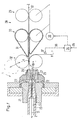
- FIG. 1 shows an exemplary embodiment of a spinning station of air-jet spinning machines for carrying out the method according to the invention.
- This spinning station is equipped for a so-called air spinning process with refinement by stretching.
- the spinning station has a means 3 for air twist distribution with a nozzle block 21 with nozzles 22 embedded therein, a spindle 23 with a yarn channel 24 and a feed block 25 with a fiber feed channel 26 and a needle 27 directed against the entrance of the yarn channel 24.
- the spinning station as a refinement unit on a drafting system 28 with, for example, three pairs of cylinders (inlet cylinder 29, central cylinder 30 with straps 31 and outlet cylinder 32 with nip 11).
- the inlet of the drafting system 28, so for example, the inlet cylinder 29 and the Central cylinder 30 with straps 31 are driven by a motor 33.
- the motor 33 is controllable by a control unit 34.
- the control unit 34 utilizes for Control of the motor 33 is a ready signal 35 and a yarn end signal 36 for the Determining the exact position of the end 2 of the yarn end 1 of a yarn end sensor 37, as well as spin-own parameters.
- the fiber longitudinal formation 10 'fed in the feed direction Z runs between the inlet cylinders 29 in the refinement, and is between inlet cylinders 29 and Center cylinders 30 a Vorverzug with a usually constant draw ratio and between center cylinders 30 and outlet cylinders 32 with a main delay subjected to an optionally variable draw ratio.
- the refined fiber longitudinal structure 10 is from the discharge cylinders 32 through the fiber feed channel 26th sucked against the entrance of Garnkanals 24. Supplied through the nozzles 22 Compressed air generated in addition to the aforementioned suction in the Garnkanaleingangs a vortex flow, which serves the twist distribution. That through this twist distribution resulting yarn 11 is through the yarn channel 24 in the withdrawal direction Z (means for Garnabzug not shown) deducted.
- the upper or lower part of the feeder block 25 and the upper or lower of the discharge cylinder 32 can be lifted from its working position, in this way that the fiber feed channel 26 and the passage between the discharge cylinders 32 for a return and positioning of the yarn end 1 is accessible.
- the Yarn end 1, which is unwound from the yarn package or an auxiliary yarn (when changing the bobbin) can be in such a equipped spinning station for the resumption of the spinning process up to the main drafting area between center cylinders 30 and aprons 31 and discharge cylinders 32 withdrawn or returned and hangs freely around the lower of the discharge cylinder 32, where it from the yarn end sensor 37th is monitored (in particular its end 2).
- the piecing process is carried out in a spinning station, as shown in FIG. 1, controlled as follows:
- the control unit For example, by personnel or by a piecing robot the ready signal 35 transmitted.
- the control unit then starts the piecing process. That the Twist distribution of the means for air-twist distribution 3 and the Garnabzug (optionally with a predetermined staggering), so that the yarn end 1 starts against the To move swirl distribution point.
- the control unit receives the yarn end signal 36, through which the actual piecing routine is started.
- the engine 33 After a delay, which first, by the relative position of the end 2 (detected by the yarn end sensor 37), second, by the position of the beginning of the end region of the longitudinal fiber structure 10 ' (just before the nip line 11), and third, by the desired length of overlapping End regions depends, the engine 33 is started.
- the engine 33 brings the Roller pairs 30 and 29 within a very short time (hundredths of a second) on a with the outlet cylinders 32 synchronized speed, so that at the time of overlap the first fibers of the end regions of the yarn end 1 and the fiber longitudinal structure 10 '
- the rollers already rotate in the correct speed ratio to each other.
- rollers can already at the beginning of the piecing or piecing process just explained Nominal or operating speed (i.e., speed of normal, steady state Spinning process). But it is also conceivable that piecing or piecing takes place at a lower speed level. Whereby after piecing all rotating rollers of the refinement unit synchronously to their respective nominal or Run up operating speed (e.g., on a ramp with a gearbox).
- control unit 34 also data with respect to the starting profile of the outlet cylinder 32, the central cylinder 30th and infeed cylinder 29, and the Garnabzuges (not shown) are available and, where appropriate, measurement data from correspondingly arranged speed sensors.
- the twist distribution of the means 3, that is in the present case the speed of the air supplied from the nozzles 22 for the preparation of the Ansetzstelle changed compared to the normal spinning process, for example for a stronger fiber turbulence can be increased.
- the upstream of an air-twist distribution in a spinning unit drafting system 28 can have only two or more than three pairs of cylinders, with a spin interruption an inlet side part of the cylinder pairs in front of an outlet side part of Cylinder pairs is stopped. This is after the spinning interruption at least the inlet side part of the cylinder pairs according to a predetermined or based on sensor signals ascertained ramp ramped up delayed.
- the figure 1 represent the center cylinder 30 and inlet cylinder 29 the inlet side (by motor 33) drivable part the refinement unit (here drafting system 28), while the discharge cylinder 32, the represent drivable parts on the outlet side.
- the position is from the end of the yarn end detected by means and transmitted to a controller, which at resumption of Production of the yarn the commissioning of the inlet side driven part of the Refinement unit delayed in time such that the end portions of the torn Longitudinal fiber structures and the yarn end overlap on a given length.
- the length of the overlapping End regions substantially the spinning distance d of the spinning station (see Figure 1).
- the spinning distance d is defined as the distance between the mouth of the spindle 23 and the nip or clamping point 11 of the outlet cylinder 32nd
- this length of the overlapping end regions is longer as said spinning distance d of the spinning station.
- the end region of the yarn end to be overlapped is 1 roughened or tapered.
- the spinning station equipped for carrying out the process according to the invention has spinning stations-internally own, controllable drive for the inlet-side parts of the refinement agent or a correspondingly controllable transmission between them upstream parts of the refining agent and a central drive.
- the other parts of the spinning station to be driven can by simple coupling to central drives or also by spinning stations-internal, possibly controllable Driven drives.
- the invention also includes a spinning station according to the invention of an air-spinning machine.
- the spinning unit according to the invention comprises a refinement unit (drafting unit) with parts which can be driven on the inlet side and outlet side, wherein at least the part which can be driven on the outlet side is equipped with at least one clamping point.
- the apparatus comprises means for air twisting, a means for yarn withdrawal, with a means for detecting the position of the end of a yarn end.
- the part of the refinement unit driven downstream can be opened in such a way that its clamping point or clamping points are exposed for a return and positioning of the yarn end.
- the part driven on the outlet side consists of at least one outlet cylinder pair (32), wherein the upper or the lower cylinder of the outlet cylinder pair can be lifted (see arrow and dashed roller in FIG. 1).
- the means for air twist distribution (3) has an effective twist stop (27) for the yarn end.
- a mandrel 27 is shown here.
- the special feature is that the twist stop (27) is effective for the yarn end and not only for the fiber longitudinal structure. This results in very good piecing.
Landscapes
- Engineering & Computer Science (AREA)
- Mechanical Engineering (AREA)
- Textile Engineering (AREA)
- Spinning Or Twisting Of Yarns (AREA)
Abstract
Description
- Inbetriebnahme der Verfeinerungseinheit (z.B. Streckwerk) mit den einlaufseitig (z.B. Einlaufzylinder und Mittelzylinder mit Riemchen) und auslaufseitig antreibbaren Teilen (z.B. Auslaufzylinder),
- Zerreissen des Faserlängsgebilde durch Abstellen des Antriebes des einlaufseitig angetriebenen Teiles (Einlauf- und Mittelzylinder) und erst anschliessendem Abstellen des auslaufseitig angetriebenen Teiles (Auslaufzylinder), wobei das Faserlängsgebilde dadurch an einer ziemlich genau durch Versuche bestimmbaren Stelle zwischen beiden Teilen reisst.
- Rückführung eines Garnendes an welchem Angesponnen oder Angesetzt werden soll zuerst durch das Mittel zum Garnabzug, dann durch das Mittel zur Drallerteilung (z.B. Mittel 3) und schliesslich durch das auslaufseitig angetriebene Teil (Auslaufzylinder des Streckwerks)
- Feststellen der Position vom Ende des Garnendes oder Mittel um Festzustellen, wann das Ende des Garnendes eine vorbestimmte Position erreicht hat.
- Inbetriebnahme des Mittels zur Luft-Drallerteilung (z.B. Mittel 3), des Mittels zum Garnabzug und der ein- sowie auslaufseitig angetriebenen Teile der Verfeinerungseinheit
- Die Rückführung des Garnendes durch das auslaufseitig angetriebenen Teil der Verfeinerungseinheit durch Öffnen des auslaufseitig angetriebenen Teiles der Verfeinerungseinheit geschieht mit anschliessender
- Positionierung des Garnendes im auslaufseitig angetriebenen Teil der Verfeinerungseinheit fluchtend mit dem Faserlängsgebilde im einlaufseitig angetriebenen Teil.
- Schliessen des auslaufseitig angetriebenen Teiles der Verfeinerungseinheit.
- Die Inbetriebnahme des auslaufseitig angetriebenen Teiles der Verfeinerungseinheit, verbunden mit einem Abzug des Garnendes durch den auslaufseitig angetriebenen Teil (Auslaufzylinder),
- gefolgt von einer zeitlich abgestimmten und verzögerten Inbetriebnahme des einlaufseitig angetriebenen Teiles ist, derart dass sich die Endbereiche des zerrissenen Faserlängsgebilde und des Garnendes überlappen und im überlappenden Zustand die Klemmstelle des auslaufseitig angetriebenen Teiles passieren.
- Inbetriebnahme der Verfeinerungseinheit (z.B. Streckwerk) mit den einlaufseitig (z.B. Einlaufzylinder und Mittelzylinder mit Riemchen) und auslaufseitig antreibbaren Teilen (z.B. Auslaufzylinder),
- Zerreissen des Faserlängsgebilde durch Abstellen des Antriebes des einlaufseitig angetriebenen Teiles (Einlauf- und Mittelzylinder) und erst anschliessendem Abstellen des auslaufseitig angetriebenen Teiles (Auslaufzylinder), wobei das Faserlängsgebilde dadurch an einer ziemlich genau durch Versuche bestimmbaren Stelle zwischen beiden Teilen reisst,
Diese beiden Schritte müssen also dem Ansetzvorgang vorgegangen sein.
In einer bevorzugten Ausführungsform der Erfindung besteht das auslaufseitig angetriebenen Teil aus mindestens einem Auslaufzylinderpaar (32), wobei der obere oder der untere Zylinder des Auslaufzylinderpaares abhebbar ist (siehe Pfeil und gestrichelte Walze in Figur 1).
In einer weiteren Ausführungsform der Erfindung kann vorgesehen werden, dass das Mittel zur Luft-Drallerteilung (3) einen für das Garnende wirksamen Drallstopp (27) aufweist. Als Beispiel wird hier ein Dorn 27 gezeigt. Die Besonderheit ist, dass der Drallstopp (27) für das Garnende wirksam ist und nicht nur für das Faserlängsgebilde. Dadurch ergeben sich besonders gute Ansetzer.
In den Ansprüchen sind weitere Ausführungsformen der Erfindung aufgeführt.
Claims (15)
- Anspinn- oder Ansetzverfahren für Spinnstellen von Luftspinnmaschinen, welche in einem Spinnprozess aus einem Faserlängsgebilde (10') ein Garn (11) herstellen und dafür eine Verfeinerungseinheit (28) mit einlaufseitig (30, 29) und auslaufseitig (32) antreibbaren Teilen mit Klemmstellen (11), ein Mittel zur Luft-Drallerteilung (3) und ein Mittel zum Garnabzug aufweisen, wobei nach einem Unterbruch des Spinnprozesses die Wiederaufnahme der Herstellung des Garnes die folgenden Schritte aufweist,dadurch gekennzeichnet, dassRückführung eines Garnendes (1) an welchem Angesponnen oder Angesetzt werden soll, zuerst durch das Mittel zum Garnabzug, dann durch das Mittel zur Drallerteilung (3) und schliesslich durch den auslaufseitig angetriebenen Teil (32) der Verfeinerungseinheit (28)Feststellen der Position vom Ende (2) des Garnendes (1)Inbetriebnahme des Mittels zur Luft-Drallerteilung (3), des Mittels zum Garnabzug und der Teile der Verfeinerungseinheit (28)die Rückführung des Garnendes (1) durch den auslaufseitig angetriebenen Teil (32) der Verfeinerungseinheit durch Öffnen des auslaufseitig angetriebenen Teiles (32) der Verfeinerungseinheit geschieht, wobei anschliessend das Garnende (1) im auslaufseitig angetriebenen Teil (32) der Verfeinerungseinheit fluchtend mit dem Faserlängsgebilde (10') im einlaufseitig angetriebenen Teil positioniert wird, und anschliessendder auslaufseitig angetriebenen Teil (32) der Verfeinerungseinheit (28) wieder geschlossen wird, und dieInbetriebnahme des auslaufseitig angetriebenen Teiles (32) der Verfeinerungseinheit (28) mit einer anschliessenden zeitlich abgestimmten und verzögerten Inbetriebnahme des einlaufseitig angetriebenen Teiles (30, 29) erfolgt, derart dass sich die Endbereiche des zerrissenen Faserlängsgebildes (10') und des Garnendes (1) überlappen und im überlappenden Zustand die Klemmstelle (11) des auslaufseitig angetriebenen Teiles (32) passieren.
- Verfahren nach Anspruch 1, dadurch gekennzeichnet, dass dem Schritt bei welchem das Garnende (1), an welchem Angesponnen oder Angesetzt werden soll, rückgeführt wird, folgende zwei Schritte vorausgehenInbetriebnahme der Verfeinerungseinheit (28) mit den einlaufseitig (30, 29) und auslaufseitig (32) antreibbaren Teilen,Zerreissen des Faserlängsgebildes (10') durch Abstellen des Antriebes (33) des einlaufseitig angetriebenen Teiles (30, 29) und erst anschliessendem Abstellen des auslaufseitig (32) angetriebenen Teiles
- Verfahren nach Anspruch 1 oder 2, dadurch gekennzeichnet, dass die Position vom Ende (2) des Garnendes (1) durch Mittel (37) erfasst einer Steuerung (34) übermittelt wird, welche bei Wiederaufnahme der Herstellung des Garnes die Inbetriebnahme des einlaufseitig angetriebenen Teiles (30, 29) der Verfeinerungseinheit (28) zeitlich derart verzögert, dass die Endbereiche des zerrissenen Faserlängsgebildes (10') und des Garnendes (1) sich auf einer vorgegeben Länge überlappen.
- Verfahren nach Anspruch 3, dadurch gekennzeichnet, dass die Länge der sich überlappenden Endbereiche im wesentlichen der Spinndistanz (d) der Spinnstelle entspricht.
- Verfahren nach Anspruch 3, dadurch gekennzeichnet, dass die Länge der sich überlappenden Endbereiche länger ist als die Spinndistanz (d) der Spinnstelle.
- Verfahren nach Anspruch 1 oder 2, dadurch gekennzeichnet, dass der zu überlappende Endbereich des Garnendes 1 aufgerauht oder verjüngt ist.
- Spinnstelle einer Luftspinnmaschine enthaltend eine Verfeinerungseinheit (28) mit einlaufseitig (29, 30) und auslaufseitig (32) antreibbaren Teilen, wobei zumindest der auslaufseitig antreibbare Teil (32) mit mindestens einer Klemmstelle (11) ausgestattet ist, mit einem Mittel zur Luft-Drallerteilung (3), einem Mittel zum Garnabzug, mit einem Mittel (37) zum Feststellen der Position vom Ende (2) eines Garnendes (1),
dadurch gekennzeichnet, dassder auslaufseitig angetriebenen Teil (32) der Verfeinerungseinheit (28) derart geöffnet werden kann, dass dessen Klemmstelle (11) oder Klemmstellen für eine Rückführung und Positionierung des Garnendes (1) freiliegt. - Vorrichtung nach Anspruch 7, dadurch gekennzeichnet, dass die einlaufseitig (29, 30) und auslaufseitig (32) antreibbaren Teile der Verfeinerungseinheit (28) unabhängig voneinander antreibbar sind.
- Vorrichtung nach Anspruch 7, dadurch gekennzeichnet, dass die Spinnstelle eine Steuerung (34) zur Ausführung des Anspinn- oder Ansetzverfahrens nach Anspruch 1 aufweist.
- Vorrichtung nach Anspruch 7, dadurch gekennzeichnet, dass die Verfeinerungseinheit (28) ein Streckwerk ist und das der einlaufseitig angetriebenen Teil (29, 30) einen Vorverzug realisiert und der auslaufseitig angetriebene Teil (32) die Auslaufklemmlinie (11) des Streckwerks darstellt.
- Vorrichtung nach Anspruch 7, dadurch gekennzeichnet, dass das Mittel (37) zum Feststellen der Position vom Ende (2) des Garnendes (1) ein Sensor ist.
- Vorrichtung nach Anspruch 7, dadurch gekennzeichnet, dass das auslaufseitig angetriebenen Teil (32) aus mindestens einem Auslaufzylinderpaar besteht, wobei der obere oder der untere Zylinder des Auslaufzylinderpaares abhebbar ist.
- Vorrichtung nach Anspruch 7, dadurch gekennzeichnet, dass das Mittel zur Luft-Drallerteilung (3) einen für das Garnende (1) wirksamen Drallstopp (27) aufweist.
- Vorrichtung nach Anspruch 12, dadurch gekennzeichnet, dass der Drallstopp (27) ein Dorn ist.
- Vorrichtung nach Anspruch 6, dadurch gekennzeichnet, dass das Mittel zur Luft-Drallerteilung (3) einen für das Garnende (1) nicht wirksamen Drallstopp aufweist.
Applications Claiming Priority (2)
| Application Number | Priority Date | Filing Date | Title |
|---|---|---|---|
| CH10672002 | 2002-06-21 | ||
| CH10672002 | 2002-06-21 |
Publications (3)
| Publication Number | Publication Date |
|---|---|
| EP1375709A2 true EP1375709A2 (de) | 2004-01-02 |
| EP1375709A3 EP1375709A3 (de) | 2004-05-12 |
| EP1375709B1 EP1375709B1 (de) | 2014-08-06 |
Family
ID=29716493
Family Applications (1)
| Application Number | Title | Priority Date | Filing Date |
|---|---|---|---|
| EP03013347.4A Expired - Lifetime EP1375709B1 (de) | 2002-06-21 | 2003-06-16 | Ansetzverfahren oder Anspinnen für Spinnstellen von Luftspinnmaschinen |
Country Status (4)
| Country | Link |
|---|---|
| US (1) | US6959532B2 (de) |
| EP (1) | EP1375709B1 (de) |
| JP (1) | JP4718108B2 (de) |
| CN (1) | CN100379911C (de) |
Cited By (3)
| Publication number | Priority date | Publication date | Assignee | Title |
|---|---|---|---|---|
| DE102011054302A1 (de) * | 2011-10-07 | 2013-04-11 | Maschinenfabrik Rieter Ag | Garnbildungselement für eine Spinnstelle einer Luftspinnmaschine mit einem Drallstoppelement |
| DE10335651B4 (de) * | 2003-07-29 | 2017-02-23 | Wilhelm Stahlecker Gmbh | Verfahren und Vorrichtung zum Wiederherstellen eines unterbrochenen Spinnvorganges |
| DE102023111660A1 (de) | 2023-05-04 | 2024-11-07 | Maschinenfabrik Rieter Ag | Luftspinnmaschine und Anspinnverfahren |
Families Citing this family (19)
| Publication number | Priority date | Publication date | Assignee | Title |
|---|---|---|---|---|
| US6802353B2 (en) * | 2001-10-10 | 2004-10-12 | The Procter & Gamble Company | Apparatus for recycling waste from an absorbent article processing line |
| US20090189319A1 (en) * | 2004-02-02 | 2009-07-30 | Kim Hak-Yong | Process of preparing continuous filament composed of nanofibers |
| EP1564317A1 (de) * | 2004-02-10 | 2005-08-17 | Maschinenfabrik Rieter Ag | Verfahren zum Erreichen einer Konstanten Ansetzermasse bei Vortex-Luftspinnverfahren |
| DE102004050968A1 (de) * | 2004-10-15 | 2006-04-20 | Wilhelm Stahlecker Gmbh | Verfahren zum Vorbereiten eines Ansetzvorganges an einer Luftdüsenspinnvorrichtung |
| CZ301752B6 (cs) * | 2005-12-20 | 2010-06-16 | Rieter Cz S.R.O. | Zpusob obnovování predení složkové príze, zejména na rotorovém doprádacím stroji pomocí spliceru a zarízení k provádení zpusobu |
| CN101294319B (zh) * | 2008-05-26 | 2010-06-02 | 东华大学 | 低落纤的喷气涡流纺装置 |
| CN101565866B (zh) * | 2009-04-17 | 2010-10-27 | 北京经纬纺机新技术有限公司 | 转杯纺纱机全自动接头控制方法及装置 |
| CZ2013275A3 (cs) * | 2013-04-09 | 2014-10-22 | Rieter Cz S.R.O. | Způsob zahájení předení na spřádacím stroji, zejména vzduchovém dopřádacím stroji nebo rotorovém dopřádacím stroji |
| CH709756A1 (de) * | 2014-06-13 | 2015-12-15 | Rieter Ag Maschf | Spinndüse für eine Luftspinnmaschine sowie Luftspinnmaschine mit einer entsprechenden Spinndüse. |
| CH709953A1 (de) * | 2014-07-30 | 2016-02-15 | Rieter Ag Maschf | Verfahren zum Betrieb einer Luftspinnmaschine. |
| CZ2015321A3 (cs) * | 2015-05-14 | 2016-12-21 | Rieter Cz S.R.O. | Způsob hromadného zapřádání příze na pracovních místech rotorového dopřádacího stroje a zařízení k jeho provádění |
| JP2017071865A (ja) * | 2015-10-06 | 2017-04-13 | 村田機械株式会社 | 紡績機 |
| DE102018007464A1 (de) * | 2018-09-21 | 2020-03-26 | Saurer Spinning Solutions Gmbh & Co. Kg | Servicewagen und Verfahren zum selbsttätigen Versorgen von Spinnstellen einer Spinnmaschine |
| CN111519286B (zh) * | 2020-04-28 | 2021-11-26 | 天津工业大学 | 一种多捻纺纱装置、多捻纺纱设备及纺纱方法 |
| CN111778601B (zh) * | 2020-06-29 | 2021-06-15 | 苏州优百纺织有限公司 | 一种断线自动接线器 |
| DE102021105058A1 (de) * | 2021-03-03 | 2022-09-08 | Maschinenfabrik Rieter Ag | Spinnstelle einer Luftspinnmaschine sowie Garnbremse für eine Spinnstelle einer Luftspinnmaschine |
| DE102021124152A1 (de) * | 2021-09-17 | 2023-03-23 | Saurer Spinning Solutions Gmbh & Co. Kg | Fadenspleißvorrichtung für eine Arbeitsstelle einer Kreuzspulen herstellenden Textilmaschine |
| LU503239B1 (de) * | 2022-12-22 | 2024-06-24 | Saurer Intelligent Technology AG | Spinnstelle einer Luftspinnmaschine sowie Verfahren zur Durchführung eines Anspinnprozesses an einer solchen Spinnstelle |
| LU503240B1 (de) * | 2022-12-22 | 2024-06-24 | Saurer Intelligent Technology AG | Faserbandvorbereitung |
Family Cites Families (8)
| Publication number | Priority date | Publication date | Assignee | Title |
|---|---|---|---|---|
| JPS5966527A (ja) * | 1982-10-07 | 1984-04-16 | Toyoda Autom Loom Works Ltd | 結束紡績装置における糸継方法 |
| US5339614A (en) | 1991-07-11 | 1994-08-23 | Maschinenfabrik Rieter Ag | Rotating disc for separating and processing the end of yarn |
| US5524427A (en) | 1992-11-10 | 1996-06-11 | Howa Machinery, Ltd. | Method and apparatus for piecing slivers in a spinning machine by throttling in a nozzle |
| KR100296977B1 (ko) | 1996-01-30 | 2001-11-22 | 무라타 기카이 가부시키가이샤 | 방적기의피이싱방법 |
| TW341605B (en) | 1996-05-16 | 1998-10-01 | Murada Kikai Kk | Piecing method for a spinning machine |
| JP2973961B2 (ja) | 1997-01-13 | 1999-11-08 | 村田機械株式会社 | 紡績機のピーシング方法及びその装置 |
| DE50104822D1 (de) | 2000-11-08 | 2005-01-20 | Rieter Ag Maschf | Steuerung von Spinnstellen in einer Spinnmaschine |
| EP1219737B2 (de) | 2000-12-22 | 2012-01-18 | Maschinenfabrik Rieter Ag | Verfahren zum Ansetzen eines in einer Spinnstelle gebildeten Garnes oder zum Anspinnen, sowie zur Durchführung des Verfahrens ausgerüstete Spinnstelle |
-
2003
- 2003-06-16 EP EP03013347.4A patent/EP1375709B1/de not_active Expired - Lifetime
- 2003-06-18 US US10/464,054 patent/US6959532B2/en not_active Expired - Lifetime
- 2003-06-20 CN CNB031438822A patent/CN100379911C/zh not_active Expired - Fee Related
- 2003-06-23 JP JP2003178317A patent/JP4718108B2/ja not_active Expired - Fee Related
Cited By (3)
| Publication number | Priority date | Publication date | Assignee | Title |
|---|---|---|---|---|
| DE10335651B4 (de) * | 2003-07-29 | 2017-02-23 | Wilhelm Stahlecker Gmbh | Verfahren und Vorrichtung zum Wiederherstellen eines unterbrochenen Spinnvorganges |
| DE102011054302A1 (de) * | 2011-10-07 | 2013-04-11 | Maschinenfabrik Rieter Ag | Garnbildungselement für eine Spinnstelle einer Luftspinnmaschine mit einem Drallstoppelement |
| DE102023111660A1 (de) | 2023-05-04 | 2024-11-07 | Maschinenfabrik Rieter Ag | Luftspinnmaschine und Anspinnverfahren |
Also Published As
| Publication number | Publication date |
|---|---|
| JP4718108B2 (ja) | 2011-07-06 |
| CN100379911C (zh) | 2008-04-09 |
| US20040045270A1 (en) | 2004-03-11 |
| EP1375709A3 (de) | 2004-05-12 |
| CN1477247A (zh) | 2004-02-25 |
| US6959532B2 (en) | 2005-11-01 |
| JP2004027473A (ja) | 2004-01-29 |
| EP1375709B1 (de) | 2014-08-06 |
Similar Documents
| Publication | Publication Date | Title |
|---|---|---|
| EP1375709B1 (de) | Ansetzverfahren oder Anspinnen für Spinnstellen von Luftspinnmaschinen | |
| EP1219737B2 (de) | Verfahren zum Ansetzen eines in einer Spinnstelle gebildeten Garnes oder zum Anspinnen, sowie zur Durchführung des Verfahrens ausgerüstete Spinnstelle | |
| DE3413894C2 (de) | ||
| EP2831319A1 (de) | Vorspinnmaschine mit einer anordnung zur detektion und entfernung von garnfehlern | |
| EP3276057A1 (de) | Fadenführungseinheit, offenend-spinnmaschine und verfahren zum betreiben einer spinnstelle | |
| DE3411577C2 (de) | ||
| EP2017377A2 (de) | Verfahren zum Betreiben einer Spinnmaschine | |
| DE3336294C2 (de) | Verfahren zum Garnansetzen beim Spinnen von Faserbündelgarnen | |
| DE10335651B4 (de) | Verfahren und Vorrichtung zum Wiederherstellen eines unterbrochenen Spinnvorganges | |
| EP1817448B1 (de) | Verfahren zum optimieren der produktionsleistung einer spinnmaschine | |
| DE3539383C2 (de) | ||
| DE3418780A1 (de) | Verfahren und vorrichtung zum vorbereiten eines abgelaengten fadenendes zum wiederanspinnen einer offenend-spinnvorrichtung | |
| EP0205962B1 (de) | Verfahren zum Anspinnen eines Garnes an einer Friktionsspinnvorrichtung | |
| DE69114951T2 (de) | Vorrichtung und Verfahren zum Auffangen und Vorbereiten des Fadenendes beim Wiederanspinnen in einer Offenendmaschine. | |
| EP2980284A2 (de) | Verfahren zur herstellung eines luftgesponnenen garnes | |
| CH685946A5 (de) | Verfahren und Vorrichtung zum automatischen Ansetzen eines neu zu spinnenden Garnes an ein bestehendes Garnende. | |
| DE68912801T2 (de) | Automatisches Wiederanspinnen eines kombinierten, auf einer Open-End-Spinnmaschine hergestellten Garns. | |
| EP1295974B1 (de) | Luftspinnvorrichtung mit Auflöseeinrichtung | |
| EP0799915A2 (de) | Verfahren und Vorrichtung zur Bandregulierung in einer Karde | |
| WO2003018887A1 (de) | Verfahren zum handhaben einer spinnvorrichtung bei einem fadenbruch | |
| EP3140233B1 (de) | Textilmaschine zur herstellung von vorgarn sowie verfahren zum starten der vorgarnherstellung an einer entsprechenden textilmaschine | |
| EP1564317A1 (de) | Verfahren zum Erreichen einer Konstanten Ansetzermasse bei Vortex-Luftspinnverfahren | |
| LU503240B1 (de) | Faserbandvorbereitung | |
| WO2024156592A1 (de) | Verfahren zum betrieb einer luftspinnmaschine sowie luftspinnmaschine | |
| DE102004006709A1 (de) | Verfahren zum Vorbereiten eines Ansetzvorganges an einer Luftdüsenspinnvorrichtung |
Legal Events
| Date | Code | Title | Description |
|---|---|---|---|
| PUAI | Public reference made under article 153(3) epc to a published international application that has entered the european phase |
Free format text: ORIGINAL CODE: 0009012 |
|
| AK | Designated contracting states |
Kind code of ref document: A2 Designated state(s): AT BE BG CH CY CZ DE DK EE ES FI FR GB GR HU IE IT LI LU MC NL PT RO SE SI SK TR |
|
| AX | Request for extension of the european patent |
Extension state: AL LT LV MK |
|
| PUAL | Search report despatched |
Free format text: ORIGINAL CODE: 0009013 |
|
| AK | Designated contracting states |
Kind code of ref document: A3 Designated state(s): AT BE BG CH CY CZ DE DK EE ES FI FR GB GR HU IE IT LI LU MC NL PT RO SE SI SK TR |
|
| AX | Request for extension of the european patent |
Extension state: AL LT LV MK |
|
| RIC1 | Information provided on ipc code assigned before grant |
Ipc: 7D 01H 4/48 A Ipc: 7D 01H 4/02 B |
|
| 17P | Request for examination filed |
Effective date: 20041105 |
|
| AKX | Designation fees paid |
Designated state(s): CH CZ ES IT LI TR |
|
| RBV | Designated contracting states (corrected) |
Designated state(s): CH CZ DE ES IT LI TR |
|
| REG | Reference to a national code |
Ref country code: DE Ref legal event code: 8566 |
|
| RBV | Designated contracting states (corrected) |
Designated state(s): CH CZ DE ES IT LI TR |
|
| 17Q | First examination report despatched |
Effective date: 20071123 |
|
| GRAP | Despatch of communication of intention to grant a patent |
Free format text: ORIGINAL CODE: EPIDOSNIGR1 |
|
| INTG | Intention to grant announced |
Effective date: 20140116 |
|
| GRAS | Grant fee paid |
Free format text: ORIGINAL CODE: EPIDOSNIGR3 |
|
| GRAA | (expected) grant |
Free format text: ORIGINAL CODE: 0009210 |
|
| AK | Designated contracting states |
Kind code of ref document: B1 Designated state(s): CH CZ DE ES IT LI TR |
|
| REG | Reference to a national code |
Ref country code: CH Ref legal event code: EP |
|
| REG | Reference to a national code |
Ref country code: DE Ref legal event code: R096 Ref document number: 50315098 Country of ref document: DE Effective date: 20140918 |
|
| PG25 | Lapsed in a contracting state [announced via postgrant information from national office to epo] |
Ref country code: ES Free format text: LAPSE BECAUSE OF FAILURE TO SUBMIT A TRANSLATION OF THE DESCRIPTION OR TO PAY THE FEE WITHIN THE PRESCRIBED TIME-LIMIT Effective date: 20140806 |
|
| PG25 | Lapsed in a contracting state [announced via postgrant information from national office to epo] |
Ref country code: CZ Free format text: LAPSE BECAUSE OF FAILURE TO SUBMIT A TRANSLATION OF THE DESCRIPTION OR TO PAY THE FEE WITHIN THE PRESCRIBED TIME-LIMIT Effective date: 20140806 Ref country code: IT Free format text: LAPSE BECAUSE OF FAILURE TO SUBMIT A TRANSLATION OF THE DESCRIPTION OR TO PAY THE FEE WITHIN THE PRESCRIBED TIME-LIMIT Effective date: 20140806 |
|
| REG | Reference to a national code |
Ref country code: DE Ref legal event code: R097 Ref document number: 50315098 Country of ref document: DE |
|
| PLBE | No opposition filed within time limit |
Free format text: ORIGINAL CODE: 0009261 |
|
| STAA | Information on the status of an ep patent application or granted ep patent |
Free format text: STATUS: NO OPPOSITION FILED WITHIN TIME LIMIT |
|
| 26N | No opposition filed |
Effective date: 20150507 |
|
| REG | Reference to a national code |
Ref country code: CH Ref legal event code: PL |
|
| PG25 | Lapsed in a contracting state [announced via postgrant information from national office to epo] |
Ref country code: LI Free format text: LAPSE BECAUSE OF NON-PAYMENT OF DUE FEES Effective date: 20150630 Ref country code: CH Free format text: LAPSE BECAUSE OF NON-PAYMENT OF DUE FEES Effective date: 20150630 |
|
| PGFP | Annual fee paid to national office [announced via postgrant information from national office to epo] |
Ref country code: DE Payment date: 20210628 Year of fee payment: 19 |
|
| PGFP | Annual fee paid to national office [announced via postgrant information from national office to epo] |
Ref country code: TR Payment date: 20210610 Year of fee payment: 19 |
|
| REG | Reference to a national code |
Ref country code: DE Ref legal event code: R119 Ref document number: 50315098 Country of ref document: DE |
|
| PG25 | Lapsed in a contracting state [announced via postgrant information from national office to epo] |
Ref country code: DE Free format text: LAPSE BECAUSE OF NON-PAYMENT OF DUE FEES Effective date: 20230103 |
|
| PG25 | Lapsed in a contracting state [announced via postgrant information from national office to epo] |
Ref country code: TR Free format text: LAPSE BECAUSE OF NON-PAYMENT OF DUE FEES Effective date: 20220616 |