EP1372963B1 - Antrieb eines zylinders - Google Patents
Antrieb eines zylinders Download PDFInfo
- Publication number
- EP1372963B1 EP1372963B1 EP02706669A EP02706669A EP1372963B1 EP 1372963 B1 EP1372963 B1 EP 1372963B1 EP 02706669 A EP02706669 A EP 02706669A EP 02706669 A EP02706669 A EP 02706669A EP 1372963 B1 EP1372963 B1 EP 1372963B1
- Authority
- EP
- European Patent Office
- Prior art keywords
- cylinder
- drive according
- gear
- clutch
- drive
- Prior art date
- Legal status (The legal status is an assumption and is not a legal conclusion. Google has not performed a legal analysis and makes no representation as to the accuracy of the status listed.)
- Expired - Lifetime
Links
Images


Classifications
-
- B—PERFORMING OPERATIONS; TRANSPORTING
- B41—PRINTING; LINING MACHINES; TYPEWRITERS; STAMPS
- B41F—PRINTING MACHINES OR PRESSES
- B41F13/00—Common details of rotary presses or machines
- B41F13/008—Mechanical features of drives, e.g. gears, clutches
-
- B—PERFORMING OPERATIONS; TRANSPORTING
- B41—PRINTING; LINING MACHINES; TYPEWRITERS; STAMPS
- B41P—INDEXING SCHEME RELATING TO PRINTING, LINING MACHINES, TYPEWRITERS, AND TO STAMPS
- B41P2213/00—Arrangements for actuating or driving printing presses; Auxiliary devices or processes
- B41P2213/10—Constitutive elements of driving devices
- B41P2213/20—Gearings
- B41P2213/206—Planetary gears
-
- B—PERFORMING OPERATIONS; TRANSPORTING
- B41—PRINTING; LINING MACHINES; TYPEWRITERS; STAMPS
- B41P—INDEXING SCHEME RELATING TO PRINTING, LINING MACHINES, TYPEWRITERS, AND TO STAMPS
- B41P2213/00—Arrangements for actuating or driving printing presses; Auxiliary devices or processes
- B41P2213/70—Driving devices associated with particular installations or situations
- B41P2213/73—Driving devices for multicolour presses
- B41P2213/734—Driving devices for multicolour presses each printing unit being driven by its own electric motor, i.e. electric shaft
Definitions
- the invention relates to a drive of a forme cylinder according to the preamble of claim 1.
- DE 44 30 693 A1 is a printing unit known, wherein the form cylinder is driven and driven off via spur gears on the transfer cylinder.
- a designed as a rotor pin of the forme cylinder is in the embodiment axially displaceable in the stator for the purpose of adjusting the side register on the forme cylinder in one embodiment. Shaping and transfer cylinders are driven in pairs in one embodiment.
- the EP 07 22 831 B1 also discloses a drive for a cylinder, wherein the driven by a motor cylinder for the purpose of adjusting the side register is arranged axially displaceable.
- a coaxially arranged on the pin of the cylinder rotor is axially movable in the stator.
- DE 196 03 663 A1 is a form cylinder via a gearbox axially and via a helical gear in the circumferential direction relative to the transfer cylinder adjustable.
- the forme cylinder and the transfer cylinder acting together with it are drivable in parallel by means of a motor.
- By means of a spigot of the forme cylinder arranged spur gear is drivable on a forme cylinder associated inking unit.
- the EP 1 000 737 A1 discloses a drive of a cylinder sleeve via a shaft which is axially clamped against a disc. Between the drive motor and sleeve an axial relative movement enabling axial coupling is provided.
- the DE 197 55 316 C2 discloses the drive of a cylinder from a drive motor via a transmission and via a "balancing clutch". Other cylinders are driven by their own drive motors. The drive motors are offset relative to each other in relation to the respective cylinder.
- the DE 38 25 307 C1 shows a drive train from a main motor via a helical gear, via a first, axially fixed shaft piece, via a second, axially movable shaft piece, via a third, axially fixed shaft piece on a bevel gear, and from there to a plate cylinder.
- the axially movable by a drive shaft piece between two eccentrically articulated and elastically deformable spring elements is arranged such that upon axial displacement of the shaft piece torsion occurs.
- the invention has for its object to provide a drive of an axially movable forme cylinder with circumferentially minimized game.
- the achievable with the present invention consist in particular in that a drive of axially movable form cylinders is created, with a game in the circumferential direction and a high production cost is minimized.
- a flexible coupling in the axial direction between the drive motor and form cylinder is arranged. It is in an advantageous embodiment as torsionally stiff but flexible in the axial direction or flexible shaft coupling, z. B. as an expansion or compensating coupling executed. Particularly advantageous is the use of a non-switchable form-locking multi-plate clutch, which is virtually no play in the circumferential direction, in contrast to other positive clutches without major manufacturing effort, and at the same time an axial change in length of the clutch itself, ie an axial movement of the forme cylinder allows.
- the coupling is positively in the axial direction, but flexible in their length or yielding, z. B. by elastic and reversible deformation, executed.
- the drive via the coupling is particularly in the case of individual drives on the individually driven cylinders, but in particular on the forme cylinder for the sake of adjustability of the side register, an advantage. If the cylinders of a printing unit are driven individually by a respective drive motor, the circumferential register can be changed by means of changes in the relative angular position of the drive motor, and the side register can be changed relative to one another by means of the axial displacement.
- the drive motors are arranged coaxially with the cylinder to be driven.
- the arrangement of the drive motor via the coupling on the forme cylinder of a jointly driven cylinder pair is advantageous.
- no movement of the drive motor must take place when pressure on and off position of the transfer cylinder, as z. T. in the drive directly on the transfer cylinder is the case
- Also based on such pivotal movements of the transfer cylinder compromise in the position of the drive motor and the engagement of the gears in the arrangement of the drive motor on the transfer cylinder can be omitted when driving the forme cylinder. The latter can lead to tooth breakage in the other case or due to the play in the drive to reduce the print quality.
- the drive motor can be arranged directly axially to the forme cylinder or to the driven cylinder.
- the forme cylinder which is flexible in the axial direction coupling between pin and drive motor can be arranged.
- the design of the drive motor with a arranged between the rotor and the pin of the cylinder gear, z. B. a planetary gear.
- an arrangement is advantageous, wherein the pinion of the drive motor does not drive directly on the spur gear of the forme cylinder.
- a simultaneous adjustment of the circumferential register would take place without additional precautions. Precautions may be, for example, a simultaneous correction over the control, which requires control engineering effort, or an allowable relative movement of the pin to the spur of the forme cylinder, but this requires guides, which are not or only with great effort in the circumferential direction to manufacture play.
- a flexible coupling in the axial direction can again be used.
- an inking unit associated with the forme cylinder and, if present, also a dampening unit is driven by the same drive motor. This saves costs and, with the correct gear ratios, ensures synchronization.
- the inking unit and the transfer cylinder are driven in parallel via the forme cylinder, at least one of the two drive lines requires the use of accessories in the case of gear trains or the use of belt drives that are as free of play as possible.
- a printing machine in particular a rotary printing press, has on a front side in a side frame, not shown, rotatably mounted pin 04.
- the pin 04 is the front side via a coupling 06 with a drive motor 07 in operative connection.
- a first embodiment is the coupling 06, as a clutch 06, in particular as a non-switchable positive shaft coupling 06 or expansion coupling 06, executed, which is connected on its side facing away from the cylinder 01 coaxially via a shaft 08 with a shaft 09 of the drive motor 07.
- a transmission 10 in particular a reduction gear 10, such.
- a planetary gear 10 arranged between the drive motor 07 and clutch 06.
- This connection between the shaft 08 and the shaft 09 may also have a non-shiftable coupling 11, z. B. via a dog clutch 11, take place.
- the clutch 11 may, if deviations in the axial direction of the cylinder 01 and the drive motor 07 are to be compensated, also be designed as a curved tooth coupling.
- the non-switchable coupling 06 is designed such that a length L in the axial direction is variable by an amount of .DELTA.L, preferably in both directions.
- the coupling 06 is formed such that it has no sliding movement in the axial direction of two circumferentially cooperating stop members relative to each other, but torsionally rigid in the circumferential direction and in the axial direction Direction yielding or reversible elastically deformable.
- the coupling 06 forming parts are positively connected with each other in the axial and circumferential direction and thus allow a large amount of manufacturing effort in the circumferential direction almost backlash drive and by changing the length L axial movement of the cylinder 01. Since no relative movement between two mutually as a stop transversely takes place to the direction of movement surfaces, the clutch 06 is wear and against Pollution insensitive.
- FIG. 1 An example of such a coupling 06, in Fig. 1 . 3 . 4 and 5 symbolically indicated only in Fig. 2 shown.
- the coupling 06 has in each case an annular flange 12 at the end face; 13, which in the circumferential direction adjacent axially extending through holes 14; 16; 17; 18 has.
- Between the two flanges 12; 13 is also a ring-shaped center piece 19 and flange 19 with holes 21; 22, and between each of the middle piece 19 and one of the flanges 12; 13 an annular plate pack 23; 24, in particular with lamellae of steel, with holes 26; 27 arranged.
- Each disk pack 23; 24 is now alternately in the circumferential direction by means of screws 28; 29 with the adjacent flange 12; 13 and the middle piece 19 so fastened that it alternately on the flange 12; 13 and the middle piece 19 is positively connected.
- the preferred blades of steel ensure in the circumferential direction, ie in the plane of their surface and perpendicular to the axis of rotation of the cylinder 01, a high rigidity, while the annular blades have low strength in the axial direction elastic or resilient properties.
- Such a coupling 06 is also referred to as a bend-compliant all-metal coupling, as a diaphragm or ring clutch.
- the coupling 06 is designed torsionally rigid and positive fit due to the rigidity of the slats in the circumferential direction.
- the alternating attachment of the plate packs 23; 24 on the flange 12; 13 and the middle piece 19 allows despite form fit in the axial direction due to the spring action of the slats in the disk set 23; 24 is a reversible change in the length L of the clutch 06 by an amount ⁇ L dependent on the dimensions of the clutch 06.
- the force to be expended, ie a spring stiffness in the coupling 06, in the axial direction depends on the Number of slats in the plate pack 23; 24.
- a torsion spring value for the torsion in the clutch 06 is greater than 10,000 Nm / °, in particular in the range between 10,000 and 20,000 Nm / °.
- the clutch 06 can also be used with only one disk pack 23; 24 and be executed without a central piece 19 or flange 19, in which case the disk set 23; 24 in the circumferential direction alternately on one and on the other flange 12; 13 is attached.
- Fig. 1 is a cooperating with the cylinder 01 second cylinder 31, z. B. a transfer cylinder 31 or an impression cylinder 31, driven by a pin 32 of the cylinder 31 by means of its own drive motor 33.
- the operative connection between the drive motor 33 and the pin 32 can also via non-switchable couplings 06; 11 (not shown).
- a transmission 10 between the drive motor 33 and cylinder 31 is also arranged here.
- the second cylinder 31 acts during printing forming a pressure point with another cylinder, not shown, for example with another transfer cylinder, with a steel cylinder or with a satellite cylinder.
- the second cylinder 31 is formed as a counter-pressure cylinder 31, it forms a pressure point together with the forme cylinder 01.
- the drive by the drive motor 07 to the connected to the clutch 06 shaft 08 is not coaxial, but via a gear 35, in particular a reduction gear 35, z. B. by means of a pinion 34 on a shaft 08 arranged on the gear 36.
- the arrangement of the coupling 11 between the drive motor 07 and the pinion 34 is advantageous for ease of separation.
- the drive motor 07 may be pre-set with a planetary gear 10 (not shown).
- a gear 40, z. B. can from the first cylinder 01 via the clutch 06 via a gear 40, z. B. by means of a pin on the pin 04 of the first cylinder 01 rotatably mounted gear 37 on a on the pin 32 of the second cylinder 31 rotatably mounted gear 38 are driven off.
- a helical gear on the pinion 34 and the gear 36 due to the now occurring higher load a helical gear on the pinion 34 and the gear 36.
- the two co-operating gears 37; 38 on the pin 04; 32 are advantageously made straight toothed, as a relative axial movement is made possible to each other without a compensation in the circumferential register is required.
- the transmission 40 is located between the clutch 06 and the cylinders 01; 31.
- the drive takes place on the respective cylinder 01; 31 as close to the respective bale, which further improves the accuracy of the drive and the print quality.
- a non-illustrated, with the first cylinder 01 cooperating inking unit 39 and possibly a dampening unit 41 via the drive motor 07 is driven.
- a drive with a clear torque flow is advantageous.
- a gear 42, 43, 44 to the inking unit 39 and possibly dampening unit 41.
- Fig. 3 is for this purpose on the pin 32 of the second cylinder 31, another gear 42 rotatably, and, cooperating with this, on the pin 04 of the first cylinder 01, a further gear 43 rotatably disposed relative to the pin 04.
- the latter meshes with a gear 44, which forms the drive for the inking unit 39 and possibly dampening unit 41.
- the drive train for the inking unit 39 and possibly dampening unit 41 forming gears 42; 43; 44 are straight teeth, so that an axial displacement of the first cylinder 01 does not lead to a relative change in the angular position between the first cylinder 01 and second cylinder 31 and first cylinder 01 and inking unit 39 and possibly dampening unit 41.
- the drive of in Fig. 3 illustrated drive connection for the common and serial drive of the cylinder 01; 31 and the inking unit 39 or dampening unit 41 can also be correspondingly Fig. 1 take place by means of a shaft 08 and the cylinder 01 coaxially arranged drive motor 07.
- a transmission 10 and possibly a clutch 11 applies accordingly.
- a third embodiment ( Fig. 4 ) is driven by the first cylinder 01 parallel to the second cylinder 31 and the inking unit 39 and possibly dampening unit 41.
- a tooth flank change is avoided with changing loads, which is arranged on the pin 04 of the first cylinder 01 gear 37 together with a gear 46, z. B. a Bei intuitionr leopardrad 46, arranged.
- About a likewise arranged on the pin 04 of the first cylinder 01 gear 47 can be aborted on the leading to drive the inking unit 39 and possibly dampening 41 gear 44.
- the drive of the shaft 08 can in one of the above ways either coaxial with the shaft 08 or via a in Fig. 4 not shown pinion 34 done.
- For the arrangement of the gear 10 and 35 and possibly a clutch 11 applies accordingly.
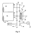
- the output from the first cylinder 01 to the second cylinder 31 does not take place on the side of the clutch 06 facing the cylinder 01, but rather on the side of the clutch 06 which is not movable in the axial direction.
- the drive connection or the transmission 40 between the first cylinder 01 and the second cylinder 01 is not between the axially variable in length L in its coupling 06 and the first cylinder 01, but on the first cylinder 01 remote from the stationary side Coupling 06 arranged.
- a gear 49 which is arranged for example on a clutch 06 encompassing the socket 48, be connected to the side facing away from the cylinder 01 side of the clutch 06.
- This gear 49 meshes on one side with a non-rotatably connected to the pin 32 of the second cylinder 31 gear 51 and the pinion 34.
- a drive level can be saved and the drive from the drive motor 07 to the cylinder 01; 31 via a helical toothing.
- the drive connection formed by the gears 49 and 51 does not lie on the side of the clutch 06 facing the cylinder 01 to be moved axially, but on the side fixed relative to an axial movement.
- Fig. 5 can be arranged coaxially with the shaft 08, waiving the pinion 34, the drive motor 07, but for a possibly existing transmission 10, the above applies.
- the planetary gear 10 shown partially advantageous The transmission 10; 35 are then preferably designed as a single-encapsulated gear, which is a lubricant inside, in particular a thin lubricant, such. As oil, may have.
- the clutch 06 is advantageous in any of the encapsulated spaces, but outside and therefore arranged easily accessible. The latter is the case in particular in connection with the formation of the coupling 06 as a membrane coupling described above.
- the drive connections between the two cylinders 01; 31 and / or one of the cylinders 01; 31 and the inking unit 39 and possibly dampening unit 41 can also be done via timing belt (taking into account a reversal of direction) or other form-locking drive connections.
- the cylinder 01 and, depending on the design, the second cylinder 31 and also the inking unit 39 and possibly dampening unit 41 are driven by means of the drive motor 07.
- Is a correction of the page register i. H. a lateral displacement of the printed image, required, so by means of a not shown, preferably arranged on the drive opposite side of the cylinder 01, drive means the cylinder 01 in the axial direction by an amount .DELTA.L moved without the drive motor 07 must also be moved ,
- the amount .DELTA.L of the displacement is absorbed by the clutch 06, wherein the cylinder 01 facing away from the end fixed, in particular stationary with respect to the axial direction, is fixed.
- the displacement does not cause simultaneous adjustment of the circumferential register.
Landscapes
- Engineering & Computer Science (AREA)
- Mechanical Engineering (AREA)
- Rotary Presses (AREA)
- Valve Device For Special Equipments (AREA)
- Actuator (AREA)
- Linear Motors (AREA)
- Inking, Control Or Cleaning Of Printing Machines (AREA)
Applications Claiming Priority (3)
| Application Number | Priority Date | Filing Date | Title |
|---|---|---|---|
| DE10114806 | 2001-03-26 | ||
| DE10114806A DE10114806A1 (de) | 2001-03-26 | 2001-03-26 | Antrieb eines Zylinders |
| PCT/DE2002/000414 WO2002076742A1 (de) | 2001-03-26 | 2002-02-05 | Antrieb eines zylinders |
Publications (2)
| Publication Number | Publication Date |
|---|---|
| EP1372963A1 EP1372963A1 (de) | 2004-01-02 |
| EP1372963B1 true EP1372963B1 (de) | 2009-06-17 |
Family
ID=7679080
Family Applications (1)
| Application Number | Title | Priority Date | Filing Date |
|---|---|---|---|
| EP02706669A Expired - Lifetime EP1372963B1 (de) | 2001-03-26 | 2002-02-05 | Antrieb eines zylinders |
Country Status (6)
| Country | Link |
|---|---|
| US (1) | US6915739B2 (enExample) |
| EP (1) | EP1372963B1 (enExample) |
| JP (1) | JP4095900B2 (enExample) |
| AT (1) | ATE433860T1 (enExample) |
| DE (2) | DE10114806A1 (enExample) |
| WO (1) | WO2002076742A1 (enExample) |
Families Citing this family (4)
| Publication number | Priority date | Publication date | Assignee | Title |
|---|---|---|---|---|
| CN100436129C (zh) * | 2003-06-09 | 2008-11-26 | 戈斯国际公司 | 可变版式胶印机 |
| DE102004040150A1 (de) * | 2004-08-19 | 2006-02-23 | Man Roland Druckmaschinen Ag | Druckeinheit sowie Farbwerk |
| DE102008009631A1 (de) | 2008-02-18 | 2009-08-27 | Heidelberger Druckmaschinen Ag | Vorrichtung zum Ein- und Auskuppeln eines Antriebes an einen Zylinder einer Verarbeitungsmaschine |
| DE102008017529A1 (de) * | 2008-04-03 | 2009-10-08 | Manroland Ag | Baugruppe einer Druckmaschine |
Citations (2)
| Publication number | Priority date | Publication date | Assignee | Title |
|---|---|---|---|---|
| DE3825307C1 (enExample) * | 1988-07-26 | 1990-01-18 | Man Roland Druckmaschinen Ag, 6050 Offenbach, De | |
| DE19539984A1 (de) * | 1995-10-27 | 1997-04-30 | Roland Man Druckmasch | Antrieb für ein Druckwerk |
Family Cites Families (13)
| Publication number | Priority date | Publication date | Assignee | Title |
|---|---|---|---|---|
| US1454087A (en) * | 1918-05-06 | 1923-05-08 | George H Thomas | Flexible coupling |
| DE2553768C3 (de) * | 1975-11-29 | 1982-03-25 | M.A.N. Maschinenfabrik Augsburg-Nürnberg AG, 8900 Augsburg | Rollen-Rotationsdruckmaschine |
| DE59304203D1 (de) | 1993-04-22 | 1996-11-21 | Baumueller Nuernberg Gmbh | Verfahren und Anordnung für einen Elektromotor zum Antrieb eines Drehkörpers, insbesondere des druckgebenden Zylinders einer Druckmaschine |
| DE4408025A1 (de) * | 1994-03-10 | 1995-09-14 | Koenig & Bauer Ag | Druckwerk für eine Mehrfarbenrollenrotationsdruckmaschine |
| DE4430693B4 (de) | 1994-08-30 | 2005-12-22 | Man Roland Druckmaschinen Ag | Antriebe für eine Rollenrotations-Offsetdruckmaschine |
| DE19603663A1 (de) | 1996-02-02 | 1997-08-07 | Roland Man Druckmasch | Druckwerk für den fliegenden Druckplattenwechsel |
| WO1998051497A2 (de) * | 1997-05-14 | 1998-11-19 | Koenig & Bauer Aktiengesellschaft | Antrieb für ein rotierendes bauteil einer rotationsdruckmaschine |
| DE19724772B4 (de) * | 1997-06-12 | 2004-02-12 | Airbus Deutschland Gmbh | Flexible Kupplung für die Wellen eines von einer zentralen Antriebseinheit angetriebenen Transmissionssystems in Luftfahrzeugen |
| DE19732330C2 (de) * | 1997-07-28 | 2001-04-19 | Koenig & Bauer Ag | Antrieb für eine Druckeinheit |
| DE19755316C2 (de) * | 1997-12-12 | 1999-10-07 | Koenig & Bauer Ag | Antrieb für Zylinder einer Druckeinheit |
| ES2172079T3 (es) * | 1998-11-06 | 2002-09-16 | Fischer & Krecke Gmbh & Co | Maquina de imprimir. |
| CN1220588C (zh) * | 2001-03-26 | 2005-09-28 | 柯尼格及包尔公开股份有限公司 | 印刷单元的驱动装置 |
| JP4403670B2 (ja) * | 2001-05-16 | 2010-01-27 | 株式会社デンソー | コンプレッサ |
-
2001
- 2001-03-26 DE DE10114806A patent/DE10114806A1/de not_active Withdrawn
-
2002
- 2002-02-05 AT AT02706669T patent/ATE433860T1/de not_active IP Right Cessation
- 2002-02-05 JP JP2002575232A patent/JP4095900B2/ja not_active Expired - Lifetime
- 2002-02-05 US US10/471,746 patent/US6915739B2/en not_active Expired - Fee Related
- 2002-02-05 EP EP02706669A patent/EP1372963B1/de not_active Expired - Lifetime
- 2002-02-05 DE DE50213617T patent/DE50213617D1/de not_active Expired - Lifetime
- 2002-02-05 WO PCT/DE2002/000414 patent/WO2002076742A1/de not_active Ceased
Patent Citations (2)
| Publication number | Priority date | Publication date | Assignee | Title |
|---|---|---|---|---|
| DE3825307C1 (enExample) * | 1988-07-26 | 1990-01-18 | Man Roland Druckmaschinen Ag, 6050 Offenbach, De | |
| DE19539984A1 (de) * | 1995-10-27 | 1997-04-30 | Roland Man Druckmasch | Antrieb für ein Druckwerk |
Also Published As
| Publication number | Publication date |
|---|---|
| JP2004518568A (ja) | 2004-06-24 |
| US6915739B2 (en) | 2005-07-12 |
| EP1372963A1 (de) | 2004-01-02 |
| ATE433860T1 (de) | 2009-07-15 |
| DE50213617D1 (de) | 2009-07-30 |
| DE10114806A1 (de) | 2002-10-17 |
| WO2002076742A1 (de) | 2002-10-03 |
| JP4095900B2 (ja) | 2008-06-04 |
| US20040050271A1 (en) | 2004-03-18 |
Similar Documents
| Publication | Publication Date | Title |
|---|---|---|
| EP1441905B1 (de) | Antrieb eines druckwerkes | |
| DE19614397C2 (de) | Antrieb mit Registervorrichtung für eine Druckeinheit einer Rollenrotationsdruckmaschine | |
| EP0741015B1 (de) | Vorrichtung zum umfänglichen und seitlichen Verstellen des Plattenzylinders | |
| DE102008046792A1 (de) | Druckmaschine mit Schmitzringen | |
| EP1459890B1 (de) | Druckwerk einer Druckmaschine | |
| DE60132649T2 (de) | Vorrichtung zur Feineinstellung der Position eines Plattenzylinders für die Ausrichtung eines Mehrfarbenbildes | |
| DE4037130A1 (de) | Vorrichtung zum verstellen der falzklappen an einem falzklappenzylinder | |
| EP1372964B1 (de) | Antrieb eines druckwerks | |
| EP1372963B1 (de) | Antrieb eines zylinders | |
| EP0707958B1 (de) | Vorrichtung zum Beseitigen von Zahnspiel | |
| DE60225218T2 (de) | Dreiteiliger Plattenzylinder mit Seiten- und Umfangsregistriereinstellungen | |
| EP0480879B2 (de) | Vorrichtung zur stufenlosen Verstellung der axialen Verreibungsbewegung von Reibwalzen | |
| EP1372962B1 (de) | Antrieb eines druckwerks | |
| DE10108745C1 (de) | Antrieb für eine Welle zum Klemmen und/oder Spannen von Aufzügen auf einem Zylinder | |
| DE10014040B4 (de) | Welle zum Synchronisieren einer Stellbewegung | |
| DE10114801B4 (de) | Antrieb eines Druckwerks | |
| EP2490894B1 (de) | Vorrichtungen in einem druckwerk einer druckmaschine | |
| CH697564B1 (de) | Rollenrotationsdruckeinheit. | |
| EP2841278B1 (de) | Druckeinheit mit wenigstens zwei mechanisch unabhängig voneinander angetriebenen, ein doppeldruckwerk ausbildenden druckwerken | |
| DE10232552B4 (de) | Antrieb eines Rotationskörpers | |
| DE10154838A1 (de) | Antrieb eines Druckwerks | |
| DE10066156B4 (de) | Welle zum Synchronisieren einer Stellbewegung | |
| DE1561079C (de) | Wellenkupplung für die einzelnen Teile der zwei- oder mehrteilig ausgebildeten Hauptantriebswelle einer Rotationsdruckmaschine mit in Reihe angeordneten Druckwerken | |
| EP1923213A2 (de) | Druckeinheit einer Druckmaschine mit zwei übereinander angeordneten Doppeldruckwerken | |
| EP2119563A2 (de) | Druckeinheit einer Druckmaschine |
Legal Events
| Date | Code | Title | Description |
|---|---|---|---|
| PUAI | Public reference made under article 153(3) epc to a published international application that has entered the european phase |
Free format text: ORIGINAL CODE: 0009012 |
|
| 17P | Request for examination filed |
Effective date: 20030616 |
|
| AK | Designated contracting states |
Kind code of ref document: A1 Designated state(s): AT BE CH CY DE DK ES FI FR GB GR IE IT LI LU MC NL PT SE TR |
|
| AX | Request for extension of the european patent |
Extension state: AL LT LV MK RO SI |
|
| 17Q | First examination report despatched |
Effective date: 20070525 |
|
| GRAP | Despatch of communication of intention to grant a patent |
Free format text: ORIGINAL CODE: EPIDOSNIGR1 |
|
| GRAS | Grant fee paid |
Free format text: ORIGINAL CODE: EPIDOSNIGR3 |
|
| GRAA | (expected) grant |
Free format text: ORIGINAL CODE: 0009210 |
|
| AK | Designated contracting states |
Kind code of ref document: B1 Designated state(s): AT BE CH CY DE DK ES FI FR GB GR IE IT LI LU MC NL PT SE TR |
|
| REG | Reference to a national code |
Ref country code: GB Ref legal event code: FG4D Free format text: NOT ENGLISH |
|
| REG | Reference to a national code |
Ref country code: CH Ref legal event code: EP |
|
| REG | Reference to a national code |
Ref country code: IE Ref legal event code: FG4D Free format text: LANGUAGE OF EP DOCUMENT: GERMAN |
|
| REF | Corresponds to: |
Ref document number: 50213617 Country of ref document: DE Date of ref document: 20090730 Kind code of ref document: P |
|
| PG25 | Lapsed in a contracting state [announced via postgrant information from national office to epo] |
Ref country code: FI Free format text: LAPSE BECAUSE OF FAILURE TO SUBMIT A TRANSLATION OF THE DESCRIPTION OR TO PAY THE FEE WITHIN THE PRESCRIBED TIME-LIMIT Effective date: 20090617 |
|
| PG25 | Lapsed in a contracting state [announced via postgrant information from national office to epo] |
Ref country code: SE Free format text: LAPSE BECAUSE OF FAILURE TO SUBMIT A TRANSLATION OF THE DESCRIPTION OR TO PAY THE FEE WITHIN THE PRESCRIBED TIME-LIMIT Effective date: 20090917 |
|
| NLV1 | Nl: lapsed or annulled due to failure to fulfill the requirements of art. 29p and 29m of the patents act | ||
| REG | Reference to a national code |
Ref country code: IE Ref legal event code: FD4D |
|
| PG25 | Lapsed in a contracting state [announced via postgrant information from national office to epo] |
Ref country code: IE Free format text: LAPSE BECAUSE OF FAILURE TO SUBMIT A TRANSLATION OF THE DESCRIPTION OR TO PAY THE FEE WITHIN THE PRESCRIBED TIME-LIMIT Effective date: 20090617 Ref country code: ES Free format text: LAPSE BECAUSE OF FAILURE TO SUBMIT A TRANSLATION OF THE DESCRIPTION OR TO PAY THE FEE WITHIN THE PRESCRIBED TIME-LIMIT Effective date: 20090928 |
|
| PG25 | Lapsed in a contracting state [announced via postgrant information from national office to epo] |
Ref country code: NL Free format text: LAPSE BECAUSE OF FAILURE TO SUBMIT A TRANSLATION OF THE DESCRIPTION OR TO PAY THE FEE WITHIN THE PRESCRIBED TIME-LIMIT Effective date: 20090617 |
|
| PLBI | Opposition filed |
Free format text: ORIGINAL CODE: 0009260 |
|
| PG25 | Lapsed in a contracting state [announced via postgrant information from national office to epo] |
Ref country code: PT Free format text: LAPSE BECAUSE OF FAILURE TO SUBMIT A TRANSLATION OF THE DESCRIPTION OR TO PAY THE FEE WITHIN THE PRESCRIBED TIME-LIMIT Effective date: 20091017 |
|
| PLAX | Notice of opposition and request to file observation + time limit sent |
Free format text: ORIGINAL CODE: EPIDOSNOBS2 |
|
| 26 | Opposition filed |
Opponent name: MANROLAND AG Effective date: 20100316 |
|
| PG25 | Lapsed in a contracting state [announced via postgrant information from national office to epo] |
Ref country code: DK Free format text: LAPSE BECAUSE OF FAILURE TO SUBMIT A TRANSLATION OF THE DESCRIPTION OR TO PAY THE FEE WITHIN THE PRESCRIBED TIME-LIMIT Effective date: 20090617 |
|
| PLBB | Reply of patent proprietor to notice(s) of opposition received |
Free format text: ORIGINAL CODE: EPIDOSNOBS3 |
|
| BERE | Be: lapsed |
Owner name: KOENIG & BAUER A.G. Effective date: 20100228 |
|
| PG25 | Lapsed in a contracting state [announced via postgrant information from national office to epo] |
Ref country code: MC Free format text: LAPSE BECAUSE OF NON-PAYMENT OF DUE FEES Effective date: 20100301 Ref country code: GR Free format text: LAPSE BECAUSE OF FAILURE TO SUBMIT A TRANSLATION OF THE DESCRIPTION OR TO PAY THE FEE WITHIN THE PRESCRIBED TIME-LIMIT Effective date: 20090918 |
|
| PG25 | Lapsed in a contracting state [announced via postgrant information from national office to epo] |
Ref country code: BE Free format text: LAPSE BECAUSE OF NON-PAYMENT OF DUE FEES Effective date: 20100228 |
|
| PG25 | Lapsed in a contracting state [announced via postgrant information from national office to epo] |
Ref country code: AT Free format text: LAPSE BECAUSE OF NON-PAYMENT OF DUE FEES Effective date: 20100205 |
|
| PLCK | Communication despatched that opposition was rejected |
Free format text: ORIGINAL CODE: EPIDOSNREJ1 |
|
| PGFP | Annual fee paid to national office [announced via postgrant information from national office to epo] |
Ref country code: CH Payment date: 20120227 Year of fee payment: 11 |
|
| PLBN | Opposition rejected |
Free format text: ORIGINAL CODE: 0009273 |
|
| STAA | Information on the status of an ep patent application or granted ep patent |
Free format text: STATUS: OPPOSITION REJECTED |
|
| PGFP | Annual fee paid to national office [announced via postgrant information from national office to epo] |
Ref country code: IT Payment date: 20120221 Year of fee payment: 11 |
|
| 27O | Opposition rejected |
Effective date: 20120308 |
|
| PG25 | Lapsed in a contracting state [announced via postgrant information from national office to epo] |
Ref country code: CY Free format text: LAPSE BECAUSE OF FAILURE TO SUBMIT A TRANSLATION OF THE DESCRIPTION OR TO PAY THE FEE WITHIN THE PRESCRIBED TIME-LIMIT Effective date: 20090617 |
|
| REG | Reference to a national code |
Ref country code: DE Ref legal event code: R100 Ref document number: 50213617 Country of ref document: DE Effective date: 20120308 |
|
| PG25 | Lapsed in a contracting state [announced via postgrant information from national office to epo] |
Ref country code: LU Free format text: LAPSE BECAUSE OF NON-PAYMENT OF DUE FEES Effective date: 20100205 |
|
| PG25 | Lapsed in a contracting state [announced via postgrant information from national office to epo] |
Ref country code: TR Free format text: LAPSE BECAUSE OF FAILURE TO SUBMIT A TRANSLATION OF THE DESCRIPTION OR TO PAY THE FEE WITHIN THE PRESCRIBED TIME-LIMIT Effective date: 20090617 |
|
| REG | Reference to a national code |
Ref country code: CH Ref legal event code: PL |
|
| PG25 | Lapsed in a contracting state [announced via postgrant information from national office to epo] |
Ref country code: LI Free format text: LAPSE BECAUSE OF NON-PAYMENT OF DUE FEES Effective date: 20130228 Ref country code: CH Free format text: LAPSE BECAUSE OF NON-PAYMENT OF DUE FEES Effective date: 20130228 |
|
| PG25 | Lapsed in a contracting state [announced via postgrant information from national office to epo] |
Ref country code: IT Free format text: LAPSE BECAUSE OF NON-PAYMENT OF DUE FEES Effective date: 20130205 |
|
| REG | Reference to a national code |
Ref country code: DE Ref legal event code: R081 Ref document number: 50213617 Country of ref document: DE Owner name: KOENIG & BAUER AG, DE Free format text: FORMER OWNER: KOENIG & BAUER AKTIENGESELLSCHAFT, 97080 WUERZBURG, DE |
|
| REG | Reference to a national code |
Ref country code: FR Ref legal event code: PLFP Year of fee payment: 15 |
|
| REG | Reference to a national code |
Ref country code: FR Ref legal event code: PLFP Year of fee payment: 16 |
|
| REG | Reference to a national code |
Ref country code: FR Ref legal event code: CA Effective date: 20170922 Ref country code: FR Ref legal event code: CD Owner name: KOENIG & BAUER AG, DE Effective date: 20170922 |
|
| REG | Reference to a national code |
Ref country code: FR Ref legal event code: PLFP Year of fee payment: 17 |
|
| PGFP | Annual fee paid to national office [announced via postgrant information from national office to epo] |
Ref country code: RO Payment date: 20190205 Year of fee payment: 9 |
|
| PGFP | Annual fee paid to national office [announced via postgrant information from national office to epo] |
Ref country code: FR Payment date: 20190224 Year of fee payment: 18 |
|
| PGFP | Annual fee paid to national office [announced via postgrant information from national office to epo] |
Ref country code: DE Payment date: 20200302 Year of fee payment: 19 |
|
| GBPC | Gb: european patent ceased through non-payment of renewal fee |
Effective date: 20200205 |
|
| PG25 | Lapsed in a contracting state [announced via postgrant information from national office to epo] |
Ref country code: FR Free format text: LAPSE BECAUSE OF NON-PAYMENT OF DUE FEES Effective date: 20200229 Ref country code: GB Free format text: LAPSE BECAUSE OF NON-PAYMENT OF DUE FEES Effective date: 20200205 |
|
| REG | Reference to a national code |
Ref country code: DE Ref legal event code: R119 Ref document number: 50213617 Country of ref document: DE |
|
| PG25 | Lapsed in a contracting state [announced via postgrant information from national office to epo] |
Ref country code: DE Free format text: LAPSE BECAUSE OF NON-PAYMENT OF DUE FEES Effective date: 20210901 |