EP1372963B1 - Drive mechanism of a cylinder - Google Patents
Drive mechanism of a cylinder Download PDFInfo
- Publication number
- EP1372963B1 EP1372963B1 EP02706669A EP02706669A EP1372963B1 EP 1372963 B1 EP1372963 B1 EP 1372963B1 EP 02706669 A EP02706669 A EP 02706669A EP 02706669 A EP02706669 A EP 02706669A EP 1372963 B1 EP1372963 B1 EP 1372963B1
- Authority
- EP
- European Patent Office
- Prior art keywords
- cylinder
- drive according
- gear
- clutch
- drive
- Prior art date
- Legal status (The legal status is an assumption and is not a legal conclusion. Google has not performed a legal analysis and makes no representation as to the accuracy of the status listed.)
- Expired - Lifetime
Links
Images


Classifications
-
- B—PERFORMING OPERATIONS; TRANSPORTING
- B41—PRINTING; LINING MACHINES; TYPEWRITERS; STAMPS
- B41F—PRINTING MACHINES OR PRESSES
- B41F13/00—Common details of rotary presses or machines
- B41F13/008—Mechanical features of drives, e.g. gears, clutches
-
- B—PERFORMING OPERATIONS; TRANSPORTING
- B41—PRINTING; LINING MACHINES; TYPEWRITERS; STAMPS
- B41P—INDEXING SCHEME RELATING TO PRINTING, LINING MACHINES, TYPEWRITERS, AND TO STAMPS
- B41P2213/00—Arrangements for actuating or driving printing presses; Auxiliary devices or processes
- B41P2213/10—Constitutive elements of driving devices
- B41P2213/20—Gearings
- B41P2213/206—Planetary gears
-
- B—PERFORMING OPERATIONS; TRANSPORTING
- B41—PRINTING; LINING MACHINES; TYPEWRITERS; STAMPS
- B41P—INDEXING SCHEME RELATING TO PRINTING, LINING MACHINES, TYPEWRITERS, AND TO STAMPS
- B41P2213/00—Arrangements for actuating or driving printing presses; Auxiliary devices or processes
- B41P2213/70—Driving devices associated with particular installations or situations
- B41P2213/73—Driving devices for multicolour presses
- B41P2213/734—Driving devices for multicolour presses each printing unit being driven by its own electric motor, i.e. electric shaft
Definitions
- the invention relates to a drive of a forme cylinder according to the preamble of claim 1.
- DE 44 30 693 A1 is a printing unit known, wherein the form cylinder is driven and driven off via spur gears on the transfer cylinder.
- a designed as a rotor pin of the forme cylinder is in the embodiment axially displaceable in the stator for the purpose of adjusting the side register on the forme cylinder in one embodiment. Shaping and transfer cylinders are driven in pairs in one embodiment.
- the EP 07 22 831 B1 also discloses a drive for a cylinder, wherein the driven by a motor cylinder for the purpose of adjusting the side register is arranged axially displaceable.
- a coaxially arranged on the pin of the cylinder rotor is axially movable in the stator.
- DE 196 03 663 A1 is a form cylinder via a gearbox axially and via a helical gear in the circumferential direction relative to the transfer cylinder adjustable.
- the forme cylinder and the transfer cylinder acting together with it are drivable in parallel by means of a motor.
- By means of a spigot of the forme cylinder arranged spur gear is drivable on a forme cylinder associated inking unit.
- the EP 1 000 737 A1 discloses a drive of a cylinder sleeve via a shaft which is axially clamped against a disc. Between the drive motor and sleeve an axial relative movement enabling axial coupling is provided.
- the DE 197 55 316 C2 discloses the drive of a cylinder from a drive motor via a transmission and via a "balancing clutch". Other cylinders are driven by their own drive motors. The drive motors are offset relative to each other in relation to the respective cylinder.
- the DE 38 25 307 C1 shows a drive train from a main motor via a helical gear, via a first, axially fixed shaft piece, via a second, axially movable shaft piece, via a third, axially fixed shaft piece on a bevel gear, and from there to a plate cylinder.
- the axially movable by a drive shaft piece between two eccentrically articulated and elastically deformable spring elements is arranged such that upon axial displacement of the shaft piece torsion occurs.
- the invention has for its object to provide a drive of an axially movable forme cylinder with circumferentially minimized game.
- the achievable with the present invention consist in particular in that a drive of axially movable form cylinders is created, with a game in the circumferential direction and a high production cost is minimized.
- a flexible coupling in the axial direction between the drive motor and form cylinder is arranged. It is in an advantageous embodiment as torsionally stiff but flexible in the axial direction or flexible shaft coupling, z. B. as an expansion or compensating coupling executed. Particularly advantageous is the use of a non-switchable form-locking multi-plate clutch, which is virtually no play in the circumferential direction, in contrast to other positive clutches without major manufacturing effort, and at the same time an axial change in length of the clutch itself, ie an axial movement of the forme cylinder allows.
- the coupling is positively in the axial direction, but flexible in their length or yielding, z. B. by elastic and reversible deformation, executed.
- the drive via the coupling is particularly in the case of individual drives on the individually driven cylinders, but in particular on the forme cylinder for the sake of adjustability of the side register, an advantage. If the cylinders of a printing unit are driven individually by a respective drive motor, the circumferential register can be changed by means of changes in the relative angular position of the drive motor, and the side register can be changed relative to one another by means of the axial displacement.
- the drive motors are arranged coaxially with the cylinder to be driven.
- the arrangement of the drive motor via the coupling on the forme cylinder of a jointly driven cylinder pair is advantageous.
- no movement of the drive motor must take place when pressure on and off position of the transfer cylinder, as z. T. in the drive directly on the transfer cylinder is the case
- Also based on such pivotal movements of the transfer cylinder compromise in the position of the drive motor and the engagement of the gears in the arrangement of the drive motor on the transfer cylinder can be omitted when driving the forme cylinder. The latter can lead to tooth breakage in the other case or due to the play in the drive to reduce the print quality.
- the drive motor can be arranged directly axially to the forme cylinder or to the driven cylinder.
- the forme cylinder which is flexible in the axial direction coupling between pin and drive motor can be arranged.
- the design of the drive motor with a arranged between the rotor and the pin of the cylinder gear, z. B. a planetary gear.
- an arrangement is advantageous, wherein the pinion of the drive motor does not drive directly on the spur gear of the forme cylinder.
- a simultaneous adjustment of the circumferential register would take place without additional precautions. Precautions may be, for example, a simultaneous correction over the control, which requires control engineering effort, or an allowable relative movement of the pin to the spur of the forme cylinder, but this requires guides, which are not or only with great effort in the circumferential direction to manufacture play.
- a flexible coupling in the axial direction can again be used.
- an inking unit associated with the forme cylinder and, if present, also a dampening unit is driven by the same drive motor. This saves costs and, with the correct gear ratios, ensures synchronization.
- the inking unit and the transfer cylinder are driven in parallel via the forme cylinder, at least one of the two drive lines requires the use of accessories in the case of gear trains or the use of belt drives that are as free of play as possible.
- a printing machine in particular a rotary printing press, has on a front side in a side frame, not shown, rotatably mounted pin 04.
- the pin 04 is the front side via a coupling 06 with a drive motor 07 in operative connection.
- a first embodiment is the coupling 06, as a clutch 06, in particular as a non-switchable positive shaft coupling 06 or expansion coupling 06, executed, which is connected on its side facing away from the cylinder 01 coaxially via a shaft 08 with a shaft 09 of the drive motor 07.
- a transmission 10 in particular a reduction gear 10, such.
- a planetary gear 10 arranged between the drive motor 07 and clutch 06.
- This connection between the shaft 08 and the shaft 09 may also have a non-shiftable coupling 11, z. B. via a dog clutch 11, take place.
- the clutch 11 may, if deviations in the axial direction of the cylinder 01 and the drive motor 07 are to be compensated, also be designed as a curved tooth coupling.
- the non-switchable coupling 06 is designed such that a length L in the axial direction is variable by an amount of .DELTA.L, preferably in both directions.
- the coupling 06 is formed such that it has no sliding movement in the axial direction of two circumferentially cooperating stop members relative to each other, but torsionally rigid in the circumferential direction and in the axial direction Direction yielding or reversible elastically deformable.
- the coupling 06 forming parts are positively connected with each other in the axial and circumferential direction and thus allow a large amount of manufacturing effort in the circumferential direction almost backlash drive and by changing the length L axial movement of the cylinder 01. Since no relative movement between two mutually as a stop transversely takes place to the direction of movement surfaces, the clutch 06 is wear and against Pollution insensitive.
- FIG. 1 An example of such a coupling 06, in Fig. 1 . 3 . 4 and 5 symbolically indicated only in Fig. 2 shown.
- the coupling 06 has in each case an annular flange 12 at the end face; 13, which in the circumferential direction adjacent axially extending through holes 14; 16; 17; 18 has.
- Between the two flanges 12; 13 is also a ring-shaped center piece 19 and flange 19 with holes 21; 22, and between each of the middle piece 19 and one of the flanges 12; 13 an annular plate pack 23; 24, in particular with lamellae of steel, with holes 26; 27 arranged.
- Each disk pack 23; 24 is now alternately in the circumferential direction by means of screws 28; 29 with the adjacent flange 12; 13 and the middle piece 19 so fastened that it alternately on the flange 12; 13 and the middle piece 19 is positively connected.
- the preferred blades of steel ensure in the circumferential direction, ie in the plane of their surface and perpendicular to the axis of rotation of the cylinder 01, a high rigidity, while the annular blades have low strength in the axial direction elastic or resilient properties.
- Such a coupling 06 is also referred to as a bend-compliant all-metal coupling, as a diaphragm or ring clutch.
- the coupling 06 is designed torsionally rigid and positive fit due to the rigidity of the slats in the circumferential direction.
- the alternating attachment of the plate packs 23; 24 on the flange 12; 13 and the middle piece 19 allows despite form fit in the axial direction due to the spring action of the slats in the disk set 23; 24 is a reversible change in the length L of the clutch 06 by an amount ⁇ L dependent on the dimensions of the clutch 06.
- the force to be expended, ie a spring stiffness in the coupling 06, in the axial direction depends on the Number of slats in the plate pack 23; 24.
- a torsion spring value for the torsion in the clutch 06 is greater than 10,000 Nm / °, in particular in the range between 10,000 and 20,000 Nm / °.
- the clutch 06 can also be used with only one disk pack 23; 24 and be executed without a central piece 19 or flange 19, in which case the disk set 23; 24 in the circumferential direction alternately on one and on the other flange 12; 13 is attached.
- Fig. 1 is a cooperating with the cylinder 01 second cylinder 31, z. B. a transfer cylinder 31 or an impression cylinder 31, driven by a pin 32 of the cylinder 31 by means of its own drive motor 33.
- the operative connection between the drive motor 33 and the pin 32 can also via non-switchable couplings 06; 11 (not shown).
- a transmission 10 between the drive motor 33 and cylinder 31 is also arranged here.
- the second cylinder 31 acts during printing forming a pressure point with another cylinder, not shown, for example with another transfer cylinder, with a steel cylinder or with a satellite cylinder.
- the second cylinder 31 is formed as a counter-pressure cylinder 31, it forms a pressure point together with the forme cylinder 01.
- the drive by the drive motor 07 to the connected to the clutch 06 shaft 08 is not coaxial, but via a gear 35, in particular a reduction gear 35, z. B. by means of a pinion 34 on a shaft 08 arranged on the gear 36.
- the arrangement of the coupling 11 between the drive motor 07 and the pinion 34 is advantageous for ease of separation.
- the drive motor 07 may be pre-set with a planetary gear 10 (not shown).
- a gear 40, z. B. can from the first cylinder 01 via the clutch 06 via a gear 40, z. B. by means of a pin on the pin 04 of the first cylinder 01 rotatably mounted gear 37 on a on the pin 32 of the second cylinder 31 rotatably mounted gear 38 are driven off.
- a helical gear on the pinion 34 and the gear 36 due to the now occurring higher load a helical gear on the pinion 34 and the gear 36.
- the two co-operating gears 37; 38 on the pin 04; 32 are advantageously made straight toothed, as a relative axial movement is made possible to each other without a compensation in the circumferential register is required.
- the transmission 40 is located between the clutch 06 and the cylinders 01; 31.
- the drive takes place on the respective cylinder 01; 31 as close to the respective bale, which further improves the accuracy of the drive and the print quality.
- a non-illustrated, with the first cylinder 01 cooperating inking unit 39 and possibly a dampening unit 41 via the drive motor 07 is driven.
- a drive with a clear torque flow is advantageous.
- a gear 42, 43, 44 to the inking unit 39 and possibly dampening unit 41.
- Fig. 3 is for this purpose on the pin 32 of the second cylinder 31, another gear 42 rotatably, and, cooperating with this, on the pin 04 of the first cylinder 01, a further gear 43 rotatably disposed relative to the pin 04.
- the latter meshes with a gear 44, which forms the drive for the inking unit 39 and possibly dampening unit 41.
- the drive train for the inking unit 39 and possibly dampening unit 41 forming gears 42; 43; 44 are straight teeth, so that an axial displacement of the first cylinder 01 does not lead to a relative change in the angular position between the first cylinder 01 and second cylinder 31 and first cylinder 01 and inking unit 39 and possibly dampening unit 41.
- the drive of in Fig. 3 illustrated drive connection for the common and serial drive of the cylinder 01; 31 and the inking unit 39 or dampening unit 41 can also be correspondingly Fig. 1 take place by means of a shaft 08 and the cylinder 01 coaxially arranged drive motor 07.
- a transmission 10 and possibly a clutch 11 applies accordingly.
- a third embodiment ( Fig. 4 ) is driven by the first cylinder 01 parallel to the second cylinder 31 and the inking unit 39 and possibly dampening unit 41.
- a tooth flank change is avoided with changing loads, which is arranged on the pin 04 of the first cylinder 01 gear 37 together with a gear 46, z. B. a Bei intuitionr leopardrad 46, arranged.
- About a likewise arranged on the pin 04 of the first cylinder 01 gear 47 can be aborted on the leading to drive the inking unit 39 and possibly dampening 41 gear 44.
- the drive of the shaft 08 can in one of the above ways either coaxial with the shaft 08 or via a in Fig. 4 not shown pinion 34 done.
- For the arrangement of the gear 10 and 35 and possibly a clutch 11 applies accordingly.
- the output from the first cylinder 01 to the second cylinder 31 does not take place on the side of the clutch 06 facing the cylinder 01, but rather on the side of the clutch 06 which is not movable in the axial direction.
- the drive connection or the transmission 40 between the first cylinder 01 and the second cylinder 01 is not between the axially variable in length L in its coupling 06 and the first cylinder 01, but on the first cylinder 01 remote from the stationary side Coupling 06 arranged.
- a gear 49 which is arranged for example on a clutch 06 encompassing the socket 48, be connected to the side facing away from the cylinder 01 side of the clutch 06.
- This gear 49 meshes on one side with a non-rotatably connected to the pin 32 of the second cylinder 31 gear 51 and the pinion 34.
- a drive level can be saved and the drive from the drive motor 07 to the cylinder 01; 31 via a helical toothing.
- the drive connection formed by the gears 49 and 51 does not lie on the side of the clutch 06 facing the cylinder 01 to be moved axially, but on the side fixed relative to an axial movement.
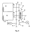
- Fig. 5 can be arranged coaxially with the shaft 08, waiving the pinion 34, the drive motor 07, but for a possibly existing transmission 10, the above applies.
- the planetary gear 10 shown partially advantageous The transmission 10; 35 are then preferably designed as a single-encapsulated gear, which is a lubricant inside, in particular a thin lubricant, such. As oil, may have.
- the clutch 06 is advantageous in any of the encapsulated spaces, but outside and therefore arranged easily accessible. The latter is the case in particular in connection with the formation of the coupling 06 as a membrane coupling described above.
- the drive connections between the two cylinders 01; 31 and / or one of the cylinders 01; 31 and the inking unit 39 and possibly dampening unit 41 can also be done via timing belt (taking into account a reversal of direction) or other form-locking drive connections.
- the cylinder 01 and, depending on the design, the second cylinder 31 and also the inking unit 39 and possibly dampening unit 41 are driven by means of the drive motor 07.
- Is a correction of the page register i. H. a lateral displacement of the printed image, required, so by means of a not shown, preferably arranged on the drive opposite side of the cylinder 01, drive means the cylinder 01 in the axial direction by an amount .DELTA.L moved without the drive motor 07 must also be moved ,
- the amount .DELTA.L of the displacement is absorbed by the clutch 06, wherein the cylinder 01 facing away from the end fixed, in particular stationary with respect to the axial direction, is fixed.
- the displacement does not cause simultaneous adjustment of the circumferential register.
Abstract
Description
Die Erfindung betrifft einen Antrieb eines Formzylinders gemäß dem Oberbegriff des Anspruchs 1.The invention relates to a drive of a forme cylinder according to the preamble of claim 1.
Durch die
Die
In der
Die
Im "
Die
Aus der
Die
Der Erfindung liegt die Aufgabe zugrunde, einen Antrieb eines axial bewegbaren Formzylinders mit in Umfangsrichtung minimierten Spiel zu schaffen.The invention has for its object to provide a drive of an axially movable forme cylinder with circumferentially minimized game.
Die Aufgabe wird erfindungsgemäß durch die Merkmale des Anspruchs 1 gelöst.The object is achieved by the features of claim 1.
Die mit der Erfindung erzielbaren Vorteile bestehen insbesondere darin, dass ein Antrieb von axial bewegbaren Formzylindern geschaffen wird, wobei ein Spiel in Umfangsrichtung und ein hoher Fertigungsaufwand minimiert wird.The achievable with the present invention consist in particular in that a drive of axially movable form cylinders is created, with a game in the circumferential direction and a high production cost is minimized.
Um eine axiale Relativbewegung zwischen dem Formzylinder, und einem den Formzylinder antreibenden Antriebsmotor zu ermöglichen, ist eine in axialer Richtung flexible Kopplung zwischen Antriebsmotor und Formzylinder angeordnet. Sie ist in vorteilhafter Ausführungsform als drehsteife aber in axialer Richtung flexible bzw. nachgiebige Wellenkupplung, z. B. als eine Ausdehnungs- oder Ausgleichskupplung, ausgeführt. Insbesondere vorteilhaft ist der Einsatz einer nichtschaltbaren formschlüssigen Lamellenkupplung, welche im Gegensatz zu anderen formschlüssigen Kupplungen ohne größeren Fertigungsaufwand in Umfangsrichtung nahezu spielfrei ist, und gleichzeitig eine axiale Längenänderung der Kupplung selbst, d. h. eine axiale Bewegung des Formzylinders, ermöglicht. Die Kupplung ist in axialer Richtung formschlüssig, jedoch in ihrer Länge flexibel bzw. nachgiebig, z. B. durch elastische und reversible Verformung, ausgeführt.To an axial relative movement between the Form cylinder, and to enable the form cylinder driving drive motor, a flexible coupling in the axial direction between the drive motor and form cylinder is arranged. It is in an advantageous embodiment as torsionally stiff but flexible in the axial direction or flexible shaft coupling, z. B. as an expansion or compensating coupling executed. Particularly advantageous is the use of a non-switchable form-locking multi-plate clutch, which is virtually no play in the circumferential direction, in contrast to other positive clutches without major manufacturing effort, and at the same time an axial change in length of the clutch itself, ie an axial movement of the forme cylinder allows. The coupling is positively in the axial direction, but flexible in their length or yielding, z. B. by elastic and reversible deformation, executed.
Der Antrieb über die Kopplung ist besonders auch im Falle von Einzelantrieben an den einzeln angetriebenen Zylindern, insbesondere jedoch am Formzylinder zwecks Verstellbarkeit des Seitenregisters, von Vorteil. Werden die Zylinder eines Druckwerks einzeln durch jeweils einen Antriebsmotor angetrieben, so lässt sich anhand von Änderungen in der relativen Winkellage des Antriebsmotors das Umfangsregister, und mittels der axialen Verschiebung das Seitenregister relativ zueinander verändern. In vorteilhafter Ausführung sind die Antriebsmotoren koaxial zum anzutreibenden Zylinder angeordnet.The drive via the coupling is particularly in the case of individual drives on the individually driven cylinders, but in particular on the forme cylinder for the sake of adjustability of the side register, an advantage. If the cylinders of a printing unit are driven individually by a respective drive motor, the circumferential register can be changed by means of changes in the relative angular position of the drive motor, and the side register can be changed relative to one another by means of the axial displacement. In an advantageous embodiment, the drive motors are arranged coaxially with the cylinder to be driven.
Für den Fall gruppenweise, insbesondere paarweise angetriebene Zylinder ist die Anordnung des Antriebsmotors über die Kopplung am Formzylinder eines gemeinsam angetriebenen Zylinderpaares vorteilhaft. Durch den Antrieb am Formzylinder muss bei Druck-An- und Ab-Stellung des Übertragungszylinders keine Bewegung des Antriebsmotors erfolgen, wie es z. T. beim Antrieb direkt am Übertragungszylinder der Fall ist Auch ein durch derartige Schwenkbewegungen des Übertragungszylinders begründeter Kompromiss bei der Lage des Antriebsmotors und dem Eingriff der Zahnräder bei Anordnung des Antriebsmotors am Übertragungszylinder kann bei Antrieb des Formzylinders entfallen. Letzteres kann im anderen Fall zu Zahnbruch oder auch aufgrund des Spiels im Antrieb zur Verminderung der Druckqualität führen.In the case of groups, especially in pairs driven cylinders, the arrangement of the drive motor via the coupling on the forme cylinder of a jointly driven cylinder pair is advantageous. By the drive on the forme cylinder no movement of the drive motor must take place when pressure on and off position of the transfer cylinder, as z. T. in the drive directly on the transfer cylinder is the case Also based on such pivotal movements of the transfer cylinder compromise in the position of the drive motor and the engagement of the gears in the arrangement of the drive motor on the transfer cylinder can be omitted when driving the forme cylinder. The latter can lead to tooth breakage in the other case or due to the play in the drive to reduce the print quality.
Ist lediglich das Farbwerk und der Übertragungszylinder an- bzw. abstellbar ausgeführt, so kann eine starre Ankopplung des Antriebsmotors an einem Seitengestell erfolgen. Generell ist es jedoch von Vorteil, auch im Hinblick auf die Druckqualität, die Rundlaufeigenschaften durch Anordnung eines Getriebes, insbesondere eines Untersetzungsgetriebes, zu verbessern.If only the inking unit and the transfer cylinder are turned on or off, a rigid coupling of the drive motor to a side frame can take place. In general, however, it is advantageous, also with regard to print quality, to improve the concentricity properties by arranging a gear, in particular a reduction gear.
In einer Ausführungsform kann der Antriebsmotor direkt axial zum Formzylinder bzw. zum angetriebenen Zylinder angeordnet sein. Um zwecks Verstellung des Seitenregisters eine axiale Bewegung des Formzylinders zu ermöglichen, ist die in axialer Richtung flexible Kopplung zwischen Zapfen und Antriebsmotor anordenbar. Vorteilhaft im Hinblick auf günstige Drehzahlbereiche, insbesondere in der Anfahrphase, ist die Ausführung des Antriebsmotors mit einem zwischen dem Rotor und dem Zapfen des Zylinders angeordneten Getriebes, z. B. eines Planetengetriebes.In one embodiment, the drive motor can be arranged directly axially to the forme cylinder or to the driven cylinder. In order to adjust the page register one To allow axial movement of the forme cylinder, which is flexible in the axial direction coupling between pin and drive motor can be arranged. Advantageous in terms of favorable speed ranges, especially in the start-up phase, the design of the drive motor with a arranged between the rotor and the pin of the cylinder gear, z. B. a planetary gear.
In Fällen, in denen die Festigkeit eine Schrägverzahnung zur Kraftübertragung fordert, ist eine Anordnung von Vorteil, wobei das Ritzel des Antriebsmotors nicht direkt auf das Stirnrad des Formzylinders treibt. Bei axialer Bewegung des Formzylinders würde so ohne zusätzliche Vorkehrungen eine gleichzeitige Verstellung des Umfangsregisters erfolgen. Vorkehrungen können beispielsweise eine gleichzeitige Korrektur über die Steuerung sein, welche regelungstechnischen Aufwand erfordert, oder aber eine zulässige Relativbewegung des Zapfens zum Stirnrad des Formzylinders, was jedoch Führungen erfordert, welche nicht oder nur mit hohem Aufwand in Umfangsrichtung spielfrei zu fertigen sind. Für eine axiale Bewegbarkeit des Formzylinders ist wieder eine in axialer Richtung flexible Kopplung einsetzbar.In cases where the strength requires a helical toothing for power transmission, an arrangement is advantageous, wherein the pinion of the drive motor does not drive directly on the spur gear of the forme cylinder. In the case of axial movement of the forme cylinder, a simultaneous adjustment of the circumferential register would take place without additional precautions. Precautions may be, for example, a simultaneous correction over the control, which requires control engineering effort, or an allowable relative movement of the pin to the spur of the forme cylinder, but this requires guides, which are not or only with great effort in the circumferential direction to manufacture play. For axial mobility of the forme cylinder, a flexible coupling in the axial direction can again be used.
Für die genannten Ausführungsformen des Antriebes des Formzylinders ist es vorteilhaft, wenn ein dem Formzylinder zugeordnetes Farbwerk, und falls vorhanden auch ein Feuchtwerk, von dem selben Antriebsmotor angetrieben wird. Dies spart Kosten und gewährleistet, die richtigen Übersetzungsverhältnisse vorausgesetzt, eine Synchronisierung.For the mentioned embodiments of the drive of the forme cylinder, it is advantageous if an inking unit associated with the forme cylinder and, if present, also a dampening unit, is driven by the same drive motor. This saves costs and, with the correct gear ratios, ensures synchronization.
Besonders günstig für ein exaktes Abwickeln der Zylinder und Walzen ist bei einem gemeinsamen Antrieb während der Produktion eine eindeutige Momentenflussrichtung vom Antriebsmotor auf die verschiedenen anzutreibenden Aggregate. Dies wird in vorteilhafter Ausführung dadurch erreicht, dass vom Formzylinder auf den Übertragungszylinder, und vom Übertragungszylinder auf das Farbwerk, d. h. seriell, getrieben wird. Dabei ist eine Ausführung besonders ökonomisch, in welcher vom Übertragungszylinder über ein drehbar auf dem Zapfen des Formzylinders angeordnetes Zahnrad auf das Farbwerk getrieben wird.In the case of a common drive during production, it is particularly favorable for an exact unwinding of the cylinders and rollers that an unambiguous direction of torque flow from the drive motor to the various units to be driven is achieved. This is achieved in an advantageous embodiment that is driven by the forme cylinder on the transfer cylinder, and from the transfer cylinder to the inking unit, ie, serially. In this case, an embodiment is particularly economical, in which from the transfer cylinder via a rotatably mounted on the journal of the forme cylinder Gear is driven to the inking unit.
Werden Farbwerk und Übertragungszylinder über den Formzylinder parallel angetrieben, so ist zumindest für einen der beiden Antriebsstränge die Verwendung von Beiläufem im Falle von Zahnradzügen, oder die Verwendung von möglichst spielfreien Riemenantrieben erforderlich.If the inking unit and the transfer cylinder are driven in parallel via the forme cylinder, at least one of the two drive lines requires the use of accessories in the case of gear trains or the use of belt drives that are as free of play as possible.
Die Maßnahmen zur Ausbildung einer drehsteifen aber axial in ihrer Länge veränderbaren Kopplung sowie zur eindeutigen Momentenflussrichtung dienen der Minimierung des Spiels im Antrieb und dadurch der Verbesserung der Druckqualität.The measures for the formation of a torsionally stiff but axially changeable in their length coupling and the unique torque flow direction of minimizing the game in the drive and thereby improving the print quality.
Ausführungsbeispiele der Erfindung sind in den Zeichnungen dargestellt und werden im folgenden näher beschrieben.Embodiments of the invention are illustrated in the drawings and will be described in more detail below.
Es zeigen:
- Fig. 1
- ein erstes Ausführungsbeispiel für den Antrieb eines Zylinders;
- Fig. 2
- ein Beispiel für eine in axiale Richtung flexible Kupplung;
- Fig. 3
- ein zweites Ausführungsbeispiel für den Antrieb eines Zylinders mit einem zweiten Zylinder und einem Farbwerk;
- Fig. 4
- ein drittes Ausführungsbeispiel für den Antrieb eines Zylinders mit einem zweiten Zylinder und einem Farbwerk;
- Fig. 5
- ein viertes Ausführungsbeispiel für den Antrieb eines Zylinders mit einem zweiten Zylinder und einem Farbwerk.
- Fig. 1
- a first embodiment for the drive of a cylinder;
- Fig. 2
- an example of an axially flexible coupling;
- Fig. 3
- a second embodiment for driving a cylinder with a second cylinder and an inking unit;
- Fig. 4
- a third embodiment for driving a cylinder with a second cylinder and an inking unit;
- Fig. 5
- A fourth embodiment for the drive of a cylinder with a second cylinder and an inking unit.
Ein erster Zylinder 01, z. B. ein Formzylinder 01, einer Druckmaschine, insbesondere einer Rotationsdruckmaschine, weist an einer Stirnseite einen in einem nicht dargestellten Seitengestell drehbar gelagerten Zapfen 04 auf. Der Zapfen 04 steht stirnseitig über eine Kopplung 06 mit einem Antriebsmotor 07 in Wirkverbindung.A
In einem ersten Ausführungsbeispiel (
Die nichtschaltbare Kupplung 06 ist derart ausgeführt, dass eine Länge L in axialer Richtung um einen Betrag von ΔL veränderbar ist, und zwar vorzugsweise in beide Richtungen. Im Gegensatz zu Klauenkupplungen oder zu Kupplungen, welche in Bohrungen eingreifende Stifte oder Bolzen aufweisen, ist die Kupplung 06 derart ausgebildet, dass sie in axialer Richtung keine Gleitbewegung zweier als Anschlag in Umfangsrichtung zusammen wirkender Teile relativ zueinander aufweist, sondern in Umfangsrichtung drehsteif und in axialer Richtung nachgiebig bzw. reversibel elastisch verformbar ist. Die die Kupplung 06 bildenden Teile sind in axialer und in Umfangsrichtung formschlüssig miteinander verbunden und ermöglichen somit ohne einen großen Fertigungsaufwand einen in Umfangsrichtung nahezu spielfreien Antrieb und durch Änderung der Länge L eine axiale Bewegung des Zylinders 01. Da keine Relativbewegung zwischen zwei gegenseitig als Anschlag quer zur Bewegungsrichtung dienenden Flächen stattfindet, ist die Kupplung 06 verschleißarm und gegen Verschmutzung unempfindlich.The
Ein Beispiel für eine derartige Kupplung 06, in
Eine derartige Kupplung 06 wird auch als biegenachgiebige Ganzmetallkupplung, als Membran- oder auch Ringkupplung bezeichnet.Such a
Durch diese Ausbildung ist die Kupplung 06 aufgrund der Steifigkeit der Lamellen in Umfangsrichtung drehsteif und formschlüssig ausgeführt. Die alternierende Befestigung der Lamellenpakete 23; 24 am Flansch 12; 13 und am Mittelstück 19 ermöglicht trotz Formschluss in axialer Richtung aufgrund der Federwirkung der Lamellen im Lamellenpaket 23; 24 eine reversible Änderung der Länge L der Kupplung 06 um einen von den Abmessungen der Kupplung 06 abhängigen Betrag ΔL. Die aufzuwendende Kraft, d. h. eine Federhärte in der Kupplung 06, in axialer Richtung ist abhängig von der Anzahl der Lamellen im Lamellenpaket 23; 24. Vorzugsweise ist ein Drehfederwert für die Torsion in der Kupplung 06 größer als 10.000 Nm/°, insbesondere im Bereich zwischen 10.000 und 20.000 Nm/°.Due to this design, the
Sind kleinere Beträge ΔL erforderlich und ist kein axialer Versatz auszugleichen, so kann die Kupplung 06 auch mit nur einem Lamellenpaket 23; 24 und ohne Mittelstück 19 bzw. Flansch 19 ausgeführt sein, wobei dann das Lamellenpaket 23; 24 in Umfangsrichtung alternierend am einen und am anderen Flansch 12; 13 befestigt ist.If smaller amounts .DELTA.L are required and no axial offset is compensated, then the clutch 06 can also be used with only one
Im Ausführungsbeispiel nach
Ist der zweite Zylinder 31 beispielsweise als Übertragungszylinder 31 ausgeführt, so wirkt dieser beim Drucken eine Druckstelle bildend mit einem weiteren, nicht dargestellten Zylinder, beispielsweise mit einem weiteren Übertragungszylinder, mit einem Stahlzylinder oder mit einem Satellitenzylinder zusammen.If the
Ist der zweite Zylinder 31 als Gegendruckzylinder 31 ausgebildet, so bildet er zusammen mit dem Formzylinder 01 eine Druckstelle.If the
In beiden Fällen ist während des Druckens u. U. eine seitliche Verschiebung des Druckbildes relativ zum Druckbild einer anderen Druckstelle oder eines anderen Formzylinders erforderlich, so dass der als Formzylinder 01 ausgebildete erste Zylinder 01 um den Betrag ΔL axial verschoben werden muss. Dieser Betrag ΔL liegt vorzugsweise zwischen 0 und ± 4 mm, insbesondere zwischen 0 und ± 2,5 mm und wird durch die Änderung der Länge L der Kupplung 06 um diesen Betrag ± ΔL aufgenommen. Das dem Formzylinder 01 abgewandte Ende der Kupplung 06, z. B. der Flansch 13, ist bezüglich einer axialen Richtung ortsfest angeordnet. Mit der Anordnung der Kupplung 06 kann der zugeordnete Antriebsmotor 07 somit bei axialer Verschiebung des Zylinders 01 orts- bzw. gestellfest angeordnet sein.In both cases, during printing u. U. a lateral displacement of the printed image relative to the printed image of another printing point or other forme cylinder required, so that designed as a
In einem zweiten Ausführungsbeispiel (
Wie in
In einer Variante wird ein nicht näher dargestelltes, mit dem ersten Zylinder 01 zusammen wirkendes Farbwerk 39 und ggf. ein Feuchtwerk 41 über den Antriebsmotor 07 mit angetrieben. Vorteilhaft ist in diesem Fall ein Antrieb mit eindeutigem Momentenfluss.In one variant, a non-illustrated, with the
Hierzu wird über die Zahnräder 37; 38 vom ersten Zylinder 01 auf den zweiten Zylinder 31, und vom zweiten Zylinder 31 über ein Getriebe 42, 43, 44 auf das Farbwerk 39 und ggf. Feuchtwerk 41 abgetrieben. In
Der Antrieb der in
In einem dritten Ausführungsbeispiel (
In einem vierten Ausführungsbeispiel (
Zwecks Raumersparnis und der Verkürzung der erforderlichen Länge der Zapfen 04; 32 kann ein Zahnrad 49, welches beispielsweise auf einer die Kupplung 06 umgreifenden Buchse 48 angeordnet ist, mit der vom Zylinder 01 abgewandten Seite der Kupplung 06 verbunden sein. Dieses Zahnrad 49 kämmt auf der einen Seite mit einem drehfest mit dem Zapfen 32 des zweiten Zylinders 31 verbundenen Zahnrades 51 und mit dem Ritzel 34. Mit dieser Ausführung kann im Vergleich zu
Im Ausführungsbeispiel nach
Für alle Ausführungsbeispiele, insbesondere für die Ausführungsvarianten mit einem koaxial zur Welle 08 angeordneten Antriebsmotor 07 ist, wie bereits zum Teil dargelegt, am Antriebsmotor 07 oder zwischen Antriebsmotor 07 und Welle 08 bzw. zwischen Antriebsmotor 33 und Zylinder 31 das zum Teil dargestellte Planetengetriebe 10 vorteilhaft. Die Getriebe 10; 35 sind dann vorzugsweise als einzeln gekapselte Getriebe ausgeführt, welche im Inneren ein Schmiermittel, insbesondere ein dünnflüssiges Schmiermittel, wie z. B. Öl, aufweisen können. Im Fall des Antriebsverbundes zwischen den beiden Zylindern 01; 31 kann in vorteilhafter Ausführung dieses Getriebe 40 ebenfalls gekapselt ausgeführt werden. Die Kupplung 06 ist jedoch vorteilhaft in keinem der gekapselten Räume, sondern außerhalb und daher leicht zugänglich angeordnet. Letzteres ist insbesondere im Zusammenhang mit der Ausbildung der Kupplung 06 als eine oben beschriebene Membrankupplung der Fall.For all embodiments, in particular for the embodiment variants with a coaxial with the
Die Antriebsverbindungen zwischen den beiden Zylindern 01; 31 und/oder einem der Zylinder 01; 31 und dem Farbwerk 39 und ggf. Feuchtwerk 41 kann auch über Zahnriemen (unter Berücksichtigung einer Drehrichtungsumkehr) oder andere formschlüssige Antriebsverbindungen erfolgen.The drive connections between the two
Die Funktionsweise des Antriebs eines Zylinders 01; 31 ist wie folgt:The operation of the drive of a
Während des Betriebes, d. h. während des Rüst- oder Produktionsbetriebes wird der Zylinder 01 und je nach Ausführung mit diesem der zweite Zylinder 31 und auch das Farbwerk 39 und ggf. Feuchtwerk 41 mittels des Antriebsmotors 07 angetrieben.During operation, d. H. During the set-up or production operation, the
Ist eine Korrektur des Seitenregisters, d. h. eine seitliche Verschiebung des Druckbildes, erforderlich, so wird mittels einer nicht dargestellten, vorzugsweise auf der dem Antrieb gegenüber liegenden Seite des Zylinders 01 angeordnete, Antriebseinrichtung der Zylinder 01 in axialer Richtung um einen Betrag ΔL verschoben, ohne dass der Antriebsmotor 07 ebenfalls verschoben werden muss. Der Betrag ΔL der Verschiebung wird von der Kupplung 06 aufgenommen, wobei deren dem Zylinder 01 abgewandtes Ende ortsfest, insbesondere Ortsfest bezüglich der axialen Richtung, festgelegt ist. Die Verschiebung verursacht keine gleichzeitige Verstellung des Umfangsregisters.Is a correction of the page register, i. H. a lateral displacement of the printed image, required, so by means of a not shown, preferably arranged on the drive opposite side of the
Sowohl eine Korrektur über eine elektronische Welle zwischen den Zylindern 01; 31, als auch ein mechanisches Nachstellen des Umfangsregisters kann entfallen.Both a correction via an electronic shaft between the
- 0101
- Zylinder, erster, FormzylinderCylinder, first, forme cylinder
- 0202
- --
- 0303
- --
- 0404
- Zapfen (01)Cones (01)
- 0505
- --
- 0606
- Kopplung, elastisch, Kupplung, Wellenkupplung, nachgiebig, AusdehnungskupplungCoupling, elastic, coupling, shaft coupling, yielding, expansion coupling
- 0707
- Antriebsmotordrive motor
- 0808
- Wellewave
- 0909
- Welle (07)Wave (07)
- 1010
- Getriebe, Untersetzungsgetriebe, PlanetengetriebeTransmission, reduction gear, planetary gear
- 1111
- Kupplung, KlauenkupplungClutch, dog clutch
- 1212
- Flansch (06)Flange (06)
- 1313
- Flansch (06)Flange (06)
- 1414
- Bohrung (12)Bore (12)
- 1515
- --
- 1616
- Bohrung (12)Bore (12)
- 1717
- Bohrung (13)Bore (13)
- 1818
- Bohrung (13)Bore (13)
- 1919
- Mittelstück, Flansch (06)Center piece, flange (06)
- 2020
- --
- 2121
- Bohrung (19)Bore (19)
- 2222
- Bohrung (19)Bore (19)
- 2323
- Lamellenpaket (06)Disc pack (06)
- 2424
- Lamellenpaket (06)Disc pack (06)
- 2525
- --
- 2626
- Bohrung (23)Bore (23)
- 2727
- Bohrung (24)Bore (24)
- 2828
- Schraube (06)Screw (06)
- 2929
- Schraube (06)Screw (06)
- 3030
- Unterlegscheibenwashers
- 3131
- Zylinder, zweiter, Übertragungszylinder, GegendruckzylinderCylinder, second, transfer cylinder, impression cylinder
- 3232
- Zapfen (31)Cones (31)
- 3333
- Antriebsmotor (31)Drive motor (31)
- 3434
- Ritzelpinion
- 3535
- Getriebe, Untersetzungsgetriebe (34, 36)Transmission, reduction gear (34, 36)
- 3636
- Zahnrad (08)Gear (08)
- 3737
- Zahnrad (04)Gear (04)
- 3838
- Zahnrad (32)Gear (32)
- 3939
- Farbwerkinking
- 4040
- Getriebe (37, 38)Transmission (37, 38)
- 4141
- Feuchtwerkdampening
- 4242
- Zahnrad (32)Gear (32)
- 4343
- Zahnrad (04)Gear (04)
- 4444
- Zahnrad (39)Gear (39)
- 4545
- --
- 4646
- Zahnrad, Beiläuferzahnrad (37)Gear, Beveling Gear (37)
- 4747
- Zahnrad (04)Gear (04)
- 4848
- BuchseRifle
- 4949
- Zahnrad (48)Gear (48)
- 5050
- --
- 5151
- Zahnrad (32)Gear (32)
- LL
- Länge (18)Length (18)
- ΔL.DELTA.L
- Betrag der Längenänderung (06), der axialen Verschiebung (01)Amount of change in length (06), axial displacement (01)
Claims (32)
- Drive of a cylinder (01) of a printing press, which cylinder (01) is in the form of a forme cylinder (01), by means of a drive motor (07), a clutch (06) which permits a relative movement in the axial direction between the forme cylinder (01) and the drive motor (07) driving the forme cylinder (01) being arranged between the drive motor (07) driving the forme cylinder (01) and the forme cylinder (01), characterized in that the clutch (06) has at least one disc pack (23; 24) connected in an interlocking manner to flanges (12; 13; 19) and is variable in its length (L) by an amount (±ΔL) in the axial direction of the forme cylinder (01; 31), and in that the forme cylinder (01) is mounted by means of a drive device so as to be displaceable by an amount (ΔL) in the axial direction so that the axial movement is taken up by the amount (ΔL) by the clutch (06).
- Drive according to Claim 1, characterized in that the clutch (06) is arranged outside a lubricant space.
- Drive according to Claim 1 or 2, characterized in that a gear (10; 35) is arranged between the drive motor (07) and the clutch (06).
- Drive according to Claim 1 or 2, characterized in that a second cylinder (31) coordinated with the cylinder (01) can be driven from the first cylinder (01) by means of the same drive motor (07) via a gear (40) effective between the cylinders (01; 31).
- Drive according to Claim 1 or 2, characterized in that a second cylinder (31) coordinated with the cylinder (01) can be driven by means of a separate drive motor (33).
- Drive according to Claim 1 or 2, characterized in that a gear (10; 35) is arranged between the second cylinder (31) and the drive motor (33).
- Drive according to Claim 1 or 2, characterized in that the drive motor (07) is arranged fixed with respect to a frame.
- Drive according to Claim 3 or 6, characterized in that the gear (10; 35) between drive motor (07) and clutch (06) is designed with a closed lubricant space as an independently encapsulated gear (10; 35).
- Drive according to Claim 8, characterized in that the clutch (06) is arranged outside a lubricant space.
- Drive according to Claim 1 or 2, characterized in that the clutch (06) is designed as a clutch (06) interlocking in the axial direction.
- Drive according to Claim 1 or 2, characterized in that the clutch (06) is designed as a clutch (06) yielding in the axial direction.
- Drive according to Claim 1 or 2, characterized in that the clutch (06) is designed as a nonrotating and unswitchable shaft clutch (06) which is interlocking in the circumferential direction.
- Drive according to Claim 1, characterized in that the clutch (06) has at least one disc pack (23; 24) connected in an interlocking manner to flanges (12; 13; 19).
- Drive according to Claim 1 or 13, characterized in that the disc pack (23; 24) is connected in the circumferential direction alternately to the flange (12; 19) facing the cylinder (01; 31) and the flange (19; 13) facing the drive motor (07).
- Drive according to Claim 1 or 5, characterized in that a shaft (09) of the drive motor (07; 33) driving the cylinder (01; 31) is arranged coaxially with and parallel to an axis of rotation of the cylinder (01; 31).
- Drive according to Claim 15, characterized in that the shaft (09) of the drive motor (07) or an extended shaft (08) has an operative connection to that side of the clutch (06) which faces away from the cylinder (01; 31).
- Drive according to Claim 1 or 2, characterized in that a shaft (08) is arranged nonrotatably on that side of the clutch (06) which faces away from the cylinder (01; 31), coaxially with and parallel to an axis of rotation of the cylinder (01; 31).
- Drive according to Claim 3 or 6, characterized in that the gear (10; 35) has a gear wheel (36) arranged nonrotatably on the shaft (08) and a pinion (34) intermeshing therewith.
- Drive according to Claim 3 or 6, characterized in that a planetary gear (10) is arranged between drive motor (07; 33) and the cylinder (01; 31).
- Drive according to Claim 1 or 2, characterized in that an inking unit (39) coordinated with the cylinder (01) and optionally a damping unit (41) can be driven by means of the same drive motor (07).
- Drive according to Claim 4, characterized in that the inking unit (39) and optionally the damping unit (41) can be driven from the second cylinder (31) via a gear (42, 43, 44).
- Drive according to Claim 4, characterized in that the gear (40) between the first cylinder (01) and the second cylinder (31) is in the form of a gear train (37, 38; 49, 44) which has a gear wheel (37; 49) connected at least nonrotatably to the journal (04) of the first cylinder (01) and a gear wheel (38; 51) cooperating with said gear wheel (37; 49) and connected nonrotatably to a journal (32) of the second cylinder (31).
- Drive according to Claim 21, characterized in that the gear (42, 43, 44) between the second cylinder (31) and the inking unit (39) and optionally the damping unit (41) is in the form of a gear train (42, 43, 44) which has a gear wheel (42) arranged nonrotatably on a journal (32) of the second cylinder (31), a gear wheel (43) cooperating with said gear wheel (42) and mounted nonrotatably on the journal (04) of the forme cylinder (01) and a gear wheel (44) of the inking unit (39) and optionally with the damping unit (41), which gear wheel (44) cooperates with said gear wheel (43).
- Drive according to Claim 1 or 2, characterized in that an inking unit (39) coordinated with the first cylinder (01) and the second cylinder (31) can be driven from the first cylinder (01) in parallel via a respective gear (40; 47, 44).
- Drive according to Claim 1 or 2, characterized in that the cylinder (01) can be axially displaced for the purpose of adjustment and/or of regulation of the side register.
- Drive according to Claim 4, characterized in that the second cylinder (31) is in the form of a transfer cylinder (31).
- Drive according to Claim 4, characterized in that the second cylinder (31) is in the form of a counter pressure cylinder (31) forming a printing point with the forme cylinder (01).
- Drive according to Claim 25, characterized in that the axial displacement is taken up by a change in a length (L) of the clutch (06).
- Drive according to Claim 1 or 2, characterized in that a torsion spring value for the torsion in the clutch is greater than 10 000 Nm/°, in particular is between 10 000 and 20 000 Nm/°.
- Drive according to Claim 1, characterized in that the cylinder (01) is axially displaceable by an amount ΔL of 0 to ± 4mm, in particular to ± 2.5 mm, from a centre position.
- Drive according to Claim 1 or 13, characterized in that the disc pack (23; 24) is annular.
- Drive according to Claim 6, characterized in that the gear (10; 35) is in the form of an individually encapsulated gear.
Applications Claiming Priority (3)
| Application Number | Priority Date | Filing Date | Title |
|---|---|---|---|
| DE10114806 | 2001-03-26 | ||
| DE10114806A DE10114806A1 (en) | 2001-03-26 | 2001-03-26 | Drive a cylinder |
| PCT/DE2002/000414 WO2002076742A1 (en) | 2001-03-26 | 2002-02-05 | Drive mechanism of a cylinder |
Publications (2)
| Publication Number | Publication Date |
|---|---|
| EP1372963A1 EP1372963A1 (en) | 2004-01-02 |
| EP1372963B1 true EP1372963B1 (en) | 2009-06-17 |
Family
ID=7679080
Family Applications (1)
| Application Number | Title | Priority Date | Filing Date |
|---|---|---|---|
| EP02706669A Expired - Lifetime EP1372963B1 (en) | 2001-03-26 | 2002-02-05 | Drive mechanism of a cylinder |
Country Status (6)
| Country | Link |
|---|---|
| US (1) | US6915739B2 (en) |
| EP (1) | EP1372963B1 (en) |
| JP (1) | JP4095900B2 (en) |
| AT (1) | ATE433860T1 (en) |
| DE (2) | DE10114806A1 (en) |
| WO (1) | WO2002076742A1 (en) |
Families Citing this family (4)
| Publication number | Priority date | Publication date | Assignee | Title |
|---|---|---|---|---|
| JP2007501724A (en) * | 2003-06-09 | 2007-02-01 | ゴス インターナショナル コーポレイション | Variable length offset printing machine |
| DE102004040150A1 (en) * | 2004-08-19 | 2006-02-23 | Man Roland Druckmaschinen Ag | Printing unit and inking unit |
| DE102008009631A1 (en) | 2008-02-18 | 2009-08-27 | Heidelberger Druckmaschinen Ag | Coupling device for coupling and decoupling plate cylinder of processing machine i.e. sheet fed rotary printing machine, with/from electric motor, has coupling half that is supported at toothed wheel in axially movable manner |
| DE102008017529A1 (en) * | 2008-04-03 | 2009-10-08 | Manroland Ag | Assembly of a printing machine |
Citations (2)
| Publication number | Priority date | Publication date | Assignee | Title |
|---|---|---|---|---|
| DE3825307C1 (en) * | 1988-07-26 | 1990-01-18 | Man Roland Druckmaschinen Ag, 6050 Offenbach, De | |
| DE19539984A1 (en) * | 1995-10-27 | 1997-04-30 | Roland Man Druckmasch | Drive for rotary printing press |
Family Cites Families (13)
| Publication number | Priority date | Publication date | Assignee | Title |
|---|---|---|---|---|
| US1454087A (en) * | 1918-05-06 | 1923-05-08 | George H Thomas | Flexible coupling |
| DE2553768C3 (en) * | 1975-11-29 | 1982-03-25 | M.A.N. Maschinenfabrik Augsburg-Nürnberg AG, 8900 Augsburg | Web-fed rotary printing press |
| ATE144184T1 (en) | 1993-04-22 | 1996-11-15 | Baumueller Nuernberg Gmbh | METHOD AND ARRANGEMENT FOR AN ELECTRIC MOTOR FOR DRIVING A ROTARY BODY, IN PARTICULAR THE PRESSURE CYLINDER OF A PRINTING MACHINE |
| DE4408025A1 (en) * | 1994-03-10 | 1995-09-14 | Koenig & Bauer Ag | Printing unit for a multi-color web-fed rotary printing machine |
| DE4430693B4 (en) | 1994-08-30 | 2005-12-22 | Man Roland Druckmaschinen Ag | Drives for a web-fed rotary offset printing machine |
| DE19603663A1 (en) | 1996-02-02 | 1997-08-07 | Roland Man Druckmasch | Printing unit for the flying printing plate change |
| BR9810411A (en) * | 1997-05-14 | 2000-08-22 | Koenig & Bauer Ag | Drive for a rotary component of a rotary press |
| DE19724772B4 (en) * | 1997-06-12 | 2004-02-12 | Airbus Deutschland Gmbh | Flexible coupling for the shafts of a transmission system in aircraft driven by a central drive unit |
| DE19732330C2 (en) * | 1997-07-28 | 2001-04-19 | Koenig & Bauer Ag | Drive for a printing unit |
| DE19755316C2 (en) * | 1997-12-12 | 1999-10-07 | Koenig & Bauer Ag | Drive for cylinders of a printing unit |
| DE59803357D1 (en) * | 1998-11-06 | 2002-04-18 | Fischer & Krecke Gmbh & Co | press |
| JP4021328B2 (en) * | 2001-03-26 | 2007-12-12 | ケーニツヒ ウント バウエル アクチエンゲゼルシヤフト | Drive unit of printing device |
| JP4403670B2 (en) * | 2001-05-16 | 2010-01-27 | 株式会社デンソー | compressor |
-
2001
- 2001-03-26 DE DE10114806A patent/DE10114806A1/en not_active Withdrawn
-
2002
- 2002-02-05 WO PCT/DE2002/000414 patent/WO2002076742A1/en active Application Filing
- 2002-02-05 DE DE50213617T patent/DE50213617D1/en not_active Expired - Lifetime
- 2002-02-05 AT AT02706669T patent/ATE433860T1/en not_active IP Right Cessation
- 2002-02-05 US US10/471,746 patent/US6915739B2/en not_active Expired - Fee Related
- 2002-02-05 EP EP02706669A patent/EP1372963B1/en not_active Expired - Lifetime
- 2002-02-05 JP JP2002575232A patent/JP4095900B2/en not_active Expired - Lifetime
Patent Citations (2)
| Publication number | Priority date | Publication date | Assignee | Title |
|---|---|---|---|---|
| DE3825307C1 (en) * | 1988-07-26 | 1990-01-18 | Man Roland Druckmaschinen Ag, 6050 Offenbach, De | |
| DE19539984A1 (en) * | 1995-10-27 | 1997-04-30 | Roland Man Druckmasch | Drive for rotary printing press |
Also Published As
| Publication number | Publication date |
|---|---|
| US20040050271A1 (en) | 2004-03-18 |
| JP2004518568A (en) | 2004-06-24 |
| DE10114806A1 (en) | 2002-10-17 |
| ATE433860T1 (en) | 2009-07-15 |
| DE50213617D1 (en) | 2009-07-30 |
| EP1372963A1 (en) | 2004-01-02 |
| WO2002076742A1 (en) | 2002-10-03 |
| US6915739B2 (en) | 2005-07-12 |
| JP4095900B2 (en) | 2008-06-04 |
Similar Documents
| Publication | Publication Date | Title |
|---|---|---|
| EP1441905B1 (en) | Drive of a printing group | |
| DE19614397C2 (en) | Drive with register device for a printing unit of a web-fed rotary printing press | |
| EP0741015B1 (en) | Circumferential and lateral register adjustment device of the plate cylinder | |
| DE102008046792A1 (en) | Printing machine with bearer rings | |
| EP1459890B1 (en) | Printing unit of a printing machine | |
| DE60132649T2 (en) | Device for finely adjusting the position of a plate cylinder for aligning a multi-color image | |
| DE4037130A1 (en) | DEVICE FOR ADJUSTING THE FOLDING FLAPS ON A FOLDING FLAP CYLINDER | |
| EP1372964B1 (en) | Drive system for a printing group | |
| EP1372963B1 (en) | Drive mechanism of a cylinder | |
| DE60225218T2 (en) | Three-piece plate cylinder with side and circumferential register settings | |
| EP0707958B1 (en) | Device for reducing gear backlash | |
| DE2921153A1 (en) | DEVICE FOR SETTING THE PAGE AND PERIODIC REGISTER IN ROTARY PRINTING MACHINES | |
| EP1372962B1 (en) | Drive mechanism of a printing unit | |
| EP0480879B2 (en) | Device for infinitely varying the axial stroke of vibrating inking rollers | |
| DE10108745C1 (en) | Drive, for shaft to clamp or tension hoists on cylinder, has boring in cylinder for third shaft | |
| DE10114801B4 (en) | Drive a printing unit | |
| EP2490894B1 (en) | Devices in a printing unit of a printing machine | |
| CH697564B1 (en) | Fed rotary printing unit. | |
| DE10232552B4 (en) | Drive a rotating body | |
| DE10154838A1 (en) | Printer drive unit comprises transmission cylinder with connection with form cylinder, motor, spur toothing, inker unit, and drive mechanism | |
| DE10066156B4 (en) | Shaft for synchronizing a positioning movement | |
| DE1561079C (en) | Shaft coupling for the individual parts of the two-part or multi-part main drive shaft of a rotary printing press with printing units arranged in series | |
| EP2119563A2 (en) | Printing unit for a printing press | |
| EP1923213A2 (en) | Printing unit of a printing press with two double printing groups arranged over each other | |
| EP1392510A1 (en) | Register control method and device |
Legal Events
| Date | Code | Title | Description |
|---|---|---|---|
| PUAI | Public reference made under article 153(3) epc to a published international application that has entered the european phase |
Free format text: ORIGINAL CODE: 0009012 |
|
| 17P | Request for examination filed |
Effective date: 20030616 |
|
| AK | Designated contracting states |
Kind code of ref document: A1 Designated state(s): AT BE CH CY DE DK ES FI FR GB GR IE IT LI LU MC NL PT SE TR |
|
| AX | Request for extension of the european patent |
Extension state: AL LT LV MK RO SI |
|
| 17Q | First examination report despatched |
Effective date: 20070525 |
|
| GRAP | Despatch of communication of intention to grant a patent |
Free format text: ORIGINAL CODE: EPIDOSNIGR1 |
|
| GRAS | Grant fee paid |
Free format text: ORIGINAL CODE: EPIDOSNIGR3 |
|
| GRAA | (expected) grant |
Free format text: ORIGINAL CODE: 0009210 |
|
| AK | Designated contracting states |
Kind code of ref document: B1 Designated state(s): AT BE CH CY DE DK ES FI FR GB GR IE IT LI LU MC NL PT SE TR |
|
| REG | Reference to a national code |
Ref country code: GB Ref legal event code: FG4D Free format text: NOT ENGLISH |
|
| REG | Reference to a national code |
Ref country code: CH Ref legal event code: EP |
|
| REG | Reference to a national code |
Ref country code: IE Ref legal event code: FG4D Free format text: LANGUAGE OF EP DOCUMENT: GERMAN |
|
| REF | Corresponds to: |
Ref document number: 50213617 Country of ref document: DE Date of ref document: 20090730 Kind code of ref document: P |
|
| PG25 | Lapsed in a contracting state [announced via postgrant information from national office to epo] |
Ref country code: FI Free format text: LAPSE BECAUSE OF FAILURE TO SUBMIT A TRANSLATION OF THE DESCRIPTION OR TO PAY THE FEE WITHIN THE PRESCRIBED TIME-LIMIT Effective date: 20090617 |
|
| PG25 | Lapsed in a contracting state [announced via postgrant information from national office to epo] |
Ref country code: SE Free format text: LAPSE BECAUSE OF FAILURE TO SUBMIT A TRANSLATION OF THE DESCRIPTION OR TO PAY THE FEE WITHIN THE PRESCRIBED TIME-LIMIT Effective date: 20090917 |
|
| NLV1 | Nl: lapsed or annulled due to failure to fulfill the requirements of art. 29p and 29m of the patents act | ||
| REG | Reference to a national code |
Ref country code: IE Ref legal event code: FD4D |
|
| PG25 | Lapsed in a contracting state [announced via postgrant information from national office to epo] |
Ref country code: IE Free format text: LAPSE BECAUSE OF FAILURE TO SUBMIT A TRANSLATION OF THE DESCRIPTION OR TO PAY THE FEE WITHIN THE PRESCRIBED TIME-LIMIT Effective date: 20090617 Ref country code: ES Free format text: LAPSE BECAUSE OF FAILURE TO SUBMIT A TRANSLATION OF THE DESCRIPTION OR TO PAY THE FEE WITHIN THE PRESCRIBED TIME-LIMIT Effective date: 20090928 |
|
| PG25 | Lapsed in a contracting state [announced via postgrant information from national office to epo] |
Ref country code: NL Free format text: LAPSE BECAUSE OF FAILURE TO SUBMIT A TRANSLATION OF THE DESCRIPTION OR TO PAY THE FEE WITHIN THE PRESCRIBED TIME-LIMIT Effective date: 20090617 |
|
| PLBI | Opposition filed |
Free format text: ORIGINAL CODE: 0009260 |
|
| PG25 | Lapsed in a contracting state [announced via postgrant information from national office to epo] |
Ref country code: PT Free format text: LAPSE BECAUSE OF FAILURE TO SUBMIT A TRANSLATION OF THE DESCRIPTION OR TO PAY THE FEE WITHIN THE PRESCRIBED TIME-LIMIT Effective date: 20091017 |
|
| PLAX | Notice of opposition and request to file observation + time limit sent |
Free format text: ORIGINAL CODE: EPIDOSNOBS2 |
|
| 26 | Opposition filed |
Opponent name: MANROLAND AG Effective date: 20100316 |
|
| PG25 | Lapsed in a contracting state [announced via postgrant information from national office to epo] |
Ref country code: DK Free format text: LAPSE BECAUSE OF FAILURE TO SUBMIT A TRANSLATION OF THE DESCRIPTION OR TO PAY THE FEE WITHIN THE PRESCRIBED TIME-LIMIT Effective date: 20090617 |
|
| PLBB | Reply of patent proprietor to notice(s) of opposition received |
Free format text: ORIGINAL CODE: EPIDOSNOBS3 |
|
| BERE | Be: lapsed |
Owner name: KOENIG & BAUER A.G. Effective date: 20100228 |
|
| PG25 | Lapsed in a contracting state [announced via postgrant information from national office to epo] |
Ref country code: MC Free format text: LAPSE BECAUSE OF NON-PAYMENT OF DUE FEES Effective date: 20100301 Ref country code: GR Free format text: LAPSE BECAUSE OF FAILURE TO SUBMIT A TRANSLATION OF THE DESCRIPTION OR TO PAY THE FEE WITHIN THE PRESCRIBED TIME-LIMIT Effective date: 20090918 |
|
| PG25 | Lapsed in a contracting state [announced via postgrant information from national office to epo] |
Ref country code: BE Free format text: LAPSE BECAUSE OF NON-PAYMENT OF DUE FEES Effective date: 20100228 |
|
| PG25 | Lapsed in a contracting state [announced via postgrant information from national office to epo] |
Ref country code: AT Free format text: LAPSE BECAUSE OF NON-PAYMENT OF DUE FEES Effective date: 20100205 |
|
| PLCK | Communication despatched that opposition was rejected |
Free format text: ORIGINAL CODE: EPIDOSNREJ1 |
|
| PGFP | Annual fee paid to national office [announced via postgrant information from national office to epo] |
Ref country code: CH Payment date: 20120227 Year of fee payment: 11 |
|
| PLBN | Opposition rejected |
Free format text: ORIGINAL CODE: 0009273 |
|
| STAA | Information on the status of an ep patent application or granted ep patent |
Free format text: STATUS: OPPOSITION REJECTED |
|
| PGFP | Annual fee paid to national office [announced via postgrant information from national office to epo] |
Ref country code: IT Payment date: 20120221 Year of fee payment: 11 |
|
| 27O | Opposition rejected |
Effective date: 20120308 |
|
| PG25 | Lapsed in a contracting state [announced via postgrant information from national office to epo] |
Ref country code: CY Free format text: LAPSE BECAUSE OF FAILURE TO SUBMIT A TRANSLATION OF THE DESCRIPTION OR TO PAY THE FEE WITHIN THE PRESCRIBED TIME-LIMIT Effective date: 20090617 |
|
| REG | Reference to a national code |
Ref country code: DE Ref legal event code: R100 Ref document number: 50213617 Country of ref document: DE Effective date: 20120308 |
|
| PG25 | Lapsed in a contracting state [announced via postgrant information from national office to epo] |
Ref country code: LU Free format text: LAPSE BECAUSE OF NON-PAYMENT OF DUE FEES Effective date: 20100205 |
|
| PG25 | Lapsed in a contracting state [announced via postgrant information from national office to epo] |
Ref country code: TR Free format text: LAPSE BECAUSE OF FAILURE TO SUBMIT A TRANSLATION OF THE DESCRIPTION OR TO PAY THE FEE WITHIN THE PRESCRIBED TIME-LIMIT Effective date: 20090617 |
|
| REG | Reference to a national code |
Ref country code: CH Ref legal event code: PL |
|
| PG25 | Lapsed in a contracting state [announced via postgrant information from national office to epo] |
Ref country code: LI Free format text: LAPSE BECAUSE OF NON-PAYMENT OF DUE FEES Effective date: 20130228 Ref country code: CH Free format text: LAPSE BECAUSE OF NON-PAYMENT OF DUE FEES Effective date: 20130228 |
|
| PG25 | Lapsed in a contracting state [announced via postgrant information from national office to epo] |
Ref country code: IT Free format text: LAPSE BECAUSE OF NON-PAYMENT OF DUE FEES Effective date: 20130205 |
|
| REG | Reference to a national code |
Ref country code: DE Ref legal event code: R081 Ref document number: 50213617 Country of ref document: DE Owner name: KOENIG & BAUER AG, DE Free format text: FORMER OWNER: KOENIG & BAUER AKTIENGESELLSCHAFT, 97080 WUERZBURG, DE |
|
| REG | Reference to a national code |
Ref country code: FR Ref legal event code: PLFP Year of fee payment: 15 |
|
| REG | Reference to a national code |
Ref country code: FR Ref legal event code: PLFP Year of fee payment: 16 |
|
| REG | Reference to a national code |
Ref country code: FR Ref legal event code: CA Effective date: 20170922 Ref country code: FR Ref legal event code: CD Owner name: KOENIG & BAUER AG, DE Effective date: 20170922 |
|
| REG | Reference to a national code |
Ref country code: FR Ref legal event code: PLFP Year of fee payment: 17 |
|
| PGFP | Annual fee paid to national office [announced via postgrant information from national office to epo] |
Ref country code: RO Payment date: 20190205 Year of fee payment: 9 |
|
| PGFP | Annual fee paid to national office [announced via postgrant information from national office to epo] |
Ref country code: FR Payment date: 20190224 Year of fee payment: 18 |
|
| PGFP | Annual fee paid to national office [announced via postgrant information from national office to epo] |
Ref country code: DE Payment date: 20200302 Year of fee payment: 19 |
|
| GBPC | Gb: european patent ceased through non-payment of renewal fee |
Effective date: 20200205 |
|
| PG25 | Lapsed in a contracting state [announced via postgrant information from national office to epo] |
Ref country code: FR Free format text: LAPSE BECAUSE OF NON-PAYMENT OF DUE FEES Effective date: 20200229 Ref country code: GB Free format text: LAPSE BECAUSE OF NON-PAYMENT OF DUE FEES Effective date: 20200205 |
|
| REG | Reference to a national code |
Ref country code: DE Ref legal event code: R119 Ref document number: 50213617 Country of ref document: DE |
|
| PG25 | Lapsed in a contracting state [announced via postgrant information from national office to epo] |
Ref country code: DE Free format text: LAPSE BECAUSE OF NON-PAYMENT OF DUE FEES Effective date: 20210901 |