EP2490894B1 - Devices in a printing unit of a printing machine - Google Patents
Devices in a printing unit of a printing machine Download PDFInfo
- Publication number
- EP2490894B1 EP2490894B1 EP10741924.4A EP10741924A EP2490894B1 EP 2490894 B1 EP2490894 B1 EP 2490894B1 EP 10741924 A EP10741924 A EP 10741924A EP 2490894 B1 EP2490894 B1 EP 2490894B1
- Authority
- EP
- European Patent Office
- Prior art keywords
- drive
- roller
- traversing
- crank
- driven
- Prior art date
- Legal status (The legal status is an assumption and is not a legal conclusion. Google has not performed a legal analysis and makes no representation as to the accuracy of the status listed.)
- Not-in-force
Links
Images


Classifications
-
- B—PERFORMING OPERATIONS; TRANSPORTING
- B41—PRINTING; LINING MACHINES; TYPEWRITERS; STAMPS
- B41F—PRINTING MACHINES OR PRESSES
- B41F31/00—Inking arrangements or devices
- B41F31/004—Driving means for ink rollers
-
- B—PERFORMING OPERATIONS; TRANSPORTING
- B41—PRINTING; LINING MACHINES; TYPEWRITERS; STAMPS
- B41F—PRINTING MACHINES OR PRESSES
- B41F13/00—Common details of rotary presses or machines
- B41F13/008—Mechanical features of drives, e.g. gears, clutches
-
- B—PERFORMING OPERATIONS; TRANSPORTING
- B41—PRINTING; LINING MACHINES; TYPEWRITERS; STAMPS
- B41F—PRINTING MACHINES OR PRESSES
- B41F31/00—Inking arrangements or devices
- B41F31/15—Devices for moving vibrator-rollers
-
- B—PERFORMING OPERATIONS; TRANSPORTING
- B41—PRINTING; LINING MACHINES; TYPEWRITERS; STAMPS
- B41P—INDEXING SCHEME RELATING TO PRINTING, LINING MACHINES, TYPEWRITERS, AND TO STAMPS
- B41P2213/00—Arrangements for actuating or driving printing presses; Auxiliary devices or processes
- B41P2213/10—Constitutive elements of driving devices
- B41P2213/25—Couplings; Clutches
Definitions
- the invention relates to a printing unit of a printing press with a device according to the preamble of claim 1.
- the WO 03/039873 A1 discloses an inking unit with two Reibzylindern, which are rotatably in one embodiment on a same machine side by a drive motor via a belt drive together, and driven by another drive motor via a crank mechanism with respect to a traversing movement.
- the belt drives on a pulley, which receives the lifting movement by a correspondingly widened running surface or by a guided on bolt movement.
- a printing unit with an inking unit wherein two distribution cylinders are rotatably driven and iridescent together arranged in a housing gearbox.
- an offset printing unit of an illustration printing machine wherein a plurality of inking cylinders of an inking unit are tempered by tempering fluid of a temperature control circuit.
- the DE 101 61 889 A1 describes an inking unit of a printing machine with a Farbreibwalze, wherein the Farbreibwalze is connected with the interposition of a permanent magnet having magnetic coupling with a drive motor.
- the two coupling halves of the magnetic coupling are not movable relative to each other in the direction of the axis of rotation.
- the DE 39 17 074 A1 and the DE 1 233 416 B1 disclose electromagnetic clutches in inking units. A compensation for a traverse stroke within the clutch is not suggested.
- the DE 103 04 296 A1 discloses a drive of a printing unit, wherein at least one inking and / or dampening roller, z. B. Reibwalze, is driven by the drive of a printing cylinder ago.
- a drive wheel arranged on the printing cylinder pin drives a traction mechanism onto a drive wheel connected to the roll neck.
- a coupling member such as a magnetic coupling, is provided, through which the arranged on the printing cylinder pin drive wheel is selectively coupled to the pin.
- An axial drive of the friction roller can be effected by means of a drive motor by means of a piston which can be acted upon with pressure medium or by magnetic force.
- a drive of a friction-driven friction roller is described, wherein in one embodiment, an axial traversing movement takes place via a crank drive driven by the machine drive and in another embodiment by a linear motor.
- the DE 10 2005 061 028 A1 discloses a printing unit of a printing press with at least one axially movably mounted roller of a inking or dampening unit, which is on a front side via an interface to the tempering a temperature control can be fed.
- a permanent magnet excited electric motor and for the axial drive a permanent magnet comprehensive linear motor is provided.
- the rotor carrying the permanent magnets of the rotary drive is rigidly connected to a roll neck.
- the invention has for its object to provide a printing unit with easy to maintain and / or variable devices.
- crank mechanism as a cross-thrust crank mechanism protects material and increases the quality, as this - in comparison to otherwise used crank drives - actually opposite phasing realized and thus a rocking of transverse movements in the printing unit are avoidable.
- a linear guide from standard high precision produced (complementary) "round parts" outer circumference of a shaft and inner surface of a round hole such as a hole
- the guide member associated with the crank comprises the one associated with a guide link.
- a required accuracy of fit can already be achieved by available on the market vendor parts.
- the low maintenance can advantageously be further increased by the fact that -. B. grease lubricated - find bearings between the guide elements use.
- a tilting of the roller and a loosening at another (simpler) position is possible.
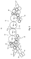
- a printing machine, z. B. web-fed rotary printing press, in particular a multi-color web-fed rotary printing press, has at least one printing unit 01, in which a web of material 02, short web 02 on both sides simply or in particular successively multiple, z. B. here four times, or multiple tracks 02 at the same time one or more times are printable.
- printing unit 01 is formed in the manner of a printing tower with a substantially vertical web run and has a plurality, in the present case, four vertically stacked double printing units 03 for the two-sided printing in rubber back-to-back operation.
- printing units 01 with a bottom-up the printing unit 01 continuous web run are preferably arranged in newspaper printing machines, said z. B. several towers and a plurality of printed through this, and downstream summarized to a product tracks 02 have.
- the double printing units 03 - shown here in the form of bridge or n-printing units - are each formed by two printing units 04, which each one as Transfer cylinder 06 and designed as a forme cylinder 07 cylinder 06; 07, z. B. printing cylinder 06; 07, and in each case have an inking unit 08 and in the case of wet offset printing additionally a dampening unit 09.
- a (double) pressure point 05 is formed in Anstelllage.
- the above components are only on the top double printing unit 03 of Fig. 1 denotes, wherein the stacked (double) printing units 03; 04 but essentially in particular in the embodiment of the relevant features of the invention - may be identical.
- the double printing units 03 can just as well, contrary to the illustration in FIG. 1, without the advantageous feature of the linear arrangement described below Fig. 1 as upwardly opening u-, downwardly opening n- or otherwise offset at the pressure point 05 unit, or as in Fig. 2 represented as a flat double printing unit 03, that is, wherein the axes of rotation of the printing cylinder 06; 07 in pressure on position z. B. in a common plane E, be executed.
- Shaping and transfer cylinder 07; 06 are z. B. with a bale width of at least two, z. B. four or even six juxtaposed standing printed pages in newspaper format, especially in broadsheet format formed.
- At least the forme cylinder 07 can in one embodiment z. B. have a circumference which essentially corresponds to two consecutively arranged printed pages in a newspaper format. In another embodiment, the scope may correspond to a single such print page.
- the inking 08, z. B. as well as a short inking unit 08 designated, two-row roller inking unit 08 executed, has a plurality of rollers 11; 12; 13; 14; 16 on.
- the inking unit 08 according to Fig. 1 and 2 includes three, the color on the printing form Rolls 11, in particular application rollers 11, which convey the ink over a dampener-remotely changeable roller 12.1, in particular a friction cylinder 12.1 (eg with a hard surface), a second, near-wetable changeable roller 12.2, in particular a friction cylinder 12.2, a further color wheel Transfer roller 13 (eg, with a soft surface), a roller 14, in particular film roller 14 and a roller 16, in particular ductor or fountain roller 16 from a color box 17 receives.
- a dampener-remotely changeable roller 12.12.1 eg with a hard surface
- a second, near-wetable changeable roller 12.2 in particular a friction cylinder 12.2
- a further color wheel Transfer roller 13
- Dipping and film roller 16; 14, which are characterizing designed as a film inking roller inking unit 08, can also be advantageous by another Farbzu Georgia- or metering, z. B. by a pumping system in Pumpfarbtechnik, or lift system in the elevator inking unit to be replaced. It is also conceivable that only two applicator rollers 11 or more than three applicator rollers 11, the ink from the friction cylinders 12.1; 12.2 transmitted to the form cylinder 07.
- the soft surfaces of the application and / or transfer rollers 11; 13, short soft rollers 11; 13, are yielding in the radial direction, z. B. with a rubber layer, formed in what Fig. 2 and 3 through the concentric circles and in Fig. 1 expressed by reinforced lines.
- the following remarks on the drive of the friction cylinder 12 or more of the distribution cylinders 12.1; 12.2 are particularly advantageous i. V. m. apply such a short sautétician feltem inking unit 08.
- the inking unit 08 as a single-inking unit 08 with two in the roller train from Farbzu Switzerland- or metering system for forme cylinder 07 serially arranged Reibzylindern 12.1; 12.2 ( Fig. 3 ) be formed.
- the following remarks on the drive of the friction cylinder 12 or more of the distribution cylinders 12.1; 12.2 are also advantageous to one or more of the distribution cylinder 12.1; 12.2 of printing units 04 with this inking 08 apply.
- Fig. 4 shows an alternative embodiment of the printing unit 01 as I-printing unit 01, wherein the printing unit 01 is traversed by the web 02 substantially vertically. It has a double printing 03 from two printing units 04, which is not predominantly horizontally, but predominantly vertically extends, ie their pairs of cylinders are not adjacent to each other, but are arranged one above the other.
- Such printing units 01 are provided in as commercial or commercial printing presses and are with regard to higher quality requirements of the products, inter alia respect.
- the printing units 04 and their drive the example of the embodiment according to Fig. 2 - as far as transferred but representative of the printing units 04 other design - explained.
- the printing cylinder 06; 07 are mechanically driven independently of other printing units 04 by at least one drive motor, not shown. As in Fig. 2 only symbolically identified, however, is preferably each printing cylinder 06; 07 driven by a separate drive motor rotationally.
- the drive is in each case from the drive shaft, via possibly a clutch directly, or via its own encapsulated transmission, z. B. reduction gear, and possibly a clutch on the pin of the respective printing cylinder 06; 07. This allows the drive without otherwise required oil space.
- At least one of the distribution cylinders 12 of the inking unit 08 is characterized by at least one drive means 18, for. B. a drive motor 18 mechanically independent of the Printing cylinders 06; 07 rotationally forcibly driven or force-driven.
- a plurality of friction cylinders 12 each have their own drive motor 18, or even a plurality of friction cylinders 12 - z. B. via a coupling or coupling gear - be assigned a common drive motor 18.
- the drive motor 18, the distribution cylinder 12; 12.1; 12.2 basically via a gear 26, z. B. via a Zahlrad-, preferably belt transmission, drive.
- the drive preferably follows via a clutch on the distribution cylinder 12. In the execution of the drive via a gear 26 can be used advantageously on standard motors without a development and production of adapted to the local application special motors would be required in small quantities.
- the first distribution cylinder 12.1 is predominantly driven in rotation via the application rollers 11 driven by friction with the forme cylinder 07 in this example, and essentially has the circumferential speed of the forme cylinder 07 independent of the indentations in the intermediate nip points.
- an optionally activatable and deactivatable mechanical drive coupling can be provided between the drive motor 18 or the positively driven distribution cylinder 12.2 and the non-positively driven distribution cylinder 12.1 (see below), or a mechanical drive coupling to the operationally not necessarily driven distribution cylinder 12.1 via a freewheeling device be provided that the freewheel in the production direction of rotation and the mechanical drive coupling against the production direction of rotation is effective. This makes it possible, the non-operational force-driven distribution cylinder 12.1 at least temporarily for set-up operations such.
- the at least one distribution cylinder 12, or at least one of a plurality of friction cylinders 12, in particular two distribution cylinders 12.1; 12.2 of the same inking unit 08, is executed with respect to its or are forcibly driven with respect to their axial traversing movement.
- the two axially positively driven distribution cylinders 12.1; Although 12.2 have mechanically independent traversing drives, but they are preferably coupled together, but at least coupled.
- z. B. the dampening remote drive cylinder 12.1 own, only his (possibly in production only by friction with an adjacent roller 11, 13 generated) rotational movement in a traversing motion forming traversing 19 have.
- this could be the rotation in an iridescent Axialhub transforming gear 19 another suitable gear 19, z. B. by an eccentric exhibiting worm or crank gear, be executed.
- the drive of the distribution cylinder 12, or the distribution cylinder 12.1; 12.2 (rotational and / or axial) formed in such a way that no extensive oil space must be provided and / or there is a simple, easily accessible maintenance and / or low wear.
- this should preferably be in conjunction with a distribution cylinder 12 or with Reibzylindern 12.1; 12.2 take place, one end face is free of drive elements, for example, a media supply, for. B. to be able to provide a connection of a Temperierstoffnikanks.
- the roller (s) 12; 12.1; 12.2 or the / the distribution cylinder 12; 12.1; 12.2 is or are then, for example, designed such that they face an interface 24 to a media circuit, for. B. a rotary feedthrough 24 for the inflow and outflow of a tempering fluid, and in the interior corresponding cavities and / or paths for the circulation of the tempering fluid has or have ( Fig. 5 ).
- Fig. 5 schematically shows an embodiment with two Reibzylindern 12.1; 12.2, the rotation and axial drive on a same machine or front side, and a media inflow, z. B. a rotary feedthrough 24, are arranged on the other side, wherein both a rotational movement transmitting gear 26 and the or the traversing gear 19 and a torque on the distribution cylinder 12 transmitting clutch 27 may be formed without oil space.
- these design features are considered individually in each case or have particular advantages in subcombinations, they in their entirety develop a preferred solution for an oil-free, maintenance-friendly and cost-effective drive of a, or in particular second temperable, distribution cylinder 12; 12.1; 12.2.
- the rotational movement transmitting gear 26 between the drive motor 18 and the distribution cylinder 12 or at least one of the distribution cylinder 12; 12.1; 12.2 omitted, due to which this is also driven oil-free.
- the two distribution cylinders 12.1; 12.2 are mounted in side frames 30 so that they can perform both a rotational movement and an axial movement. On one of the sides of the machine in each case an above-mentioned rotating union 24 may be provided. On the other side of the machine is at least one of the two distribution cylinders 12.2 (see above) by the drive motor 18 via the belt drive 26 with a belt 36, in particular toothed belt 36, trained gear 26 forcibly driven or positively driven.
- the other (or more other) distribution cylinder 12.1 is not operatively coupled to the drive motor 18, and may be with its pin 28 via z. B.
- a thrust bearing 49 tension and compression stiff (or -fest), but freely movable with respect to a relative rotational movement, and possibly additionally coupled via a rigid, but releasable coupling, not shown, to the traversing gear 19.1.
- the torque of the rotary drive is transmitted from the drive motor 18 to a pin 28 of the distribution cylinder 12.2 by a coupling 27 designed as a magnetic coupling 27.
- the gear 26 may be formed oil-free.
- a smaller sized motor, z. As well as a standard motor can be used. If necessary, in setup mode, eg. B.
- the or preferably both distribution cylinders 12.1; 12.2 is or are in terms of their axial movement via a respective traversing gear 19.1; 19.2 positively driven, which in particular each as the rotational movement in a linear motion forming cross thrust crank drives 19.1; 19.2 are formed or at least include such kind.
- the traversing gear 19.1; 19.2, z. B. via a gear 29, for example, a corner gear or worm gear, driven by the drive motor 18 different drive motor 23.
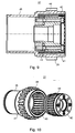
- Fig. 10 shows a perspective view of a magnetic coupling 27 in the extended state.
- the clutch 27 is preferably arranged coaxially to the axis of rotation of the friction cylinder 12 and its pin.
- Roller The magnetic coupling 27 comprises two coaxially arranged rotors 41; 42, namely an outer rotor 41 and an inner rotor 42, wherein the outer rotor 41 on its inner side and the inner rotor 42 on its outside with (high-quality) magnet 43; 44, in particular permanent magnet 43; 44 alternating polarity are equipped, ie alternate in the circumferential direction north and south poles. At rest, the respective north and south poles of outer rotor 41 and inner rotor 42 are opposite.
- the outer rotor 41 has on its circumference a race 38, z. B. an external toothing 38, on which or which with the belt 36, z. B. an internal toothing of the toothed belt 36, for the purpose of driving the outer rotor 41 cooperates. So that the outer rotor 41 can rotate, it is rotatably mounted in or on the side frame 30 via a radial bearing 39.
- the outer rotor 41 is driven by the drive motor 18 via the belt 36.
- the drive motor 18 is preferably arranged fixed to the frame and, for example, via a non-designated frame, for. B. via studs, a housing or a base, connected to the side frame 30.
- the inner rotor 42 is, for. B. via a clamping connection 48 (eg., A clamping set) with the pin 28 of the Reibzylinders 12.2 torsionally rigid and tensile and pressure rigid (or -fest) connected.
- a clamping connection 48 eg., A clamping set
- the outer rotor 41 is thus frame-fixed with respect to an axial movement, and the inner rotor 42 relative to the outer rotor 41 by the maximum amplitude of the traverse stroke, z. B. by at least 10 mm, in particular by at least 20 mm, in the example about 30 mm, axially movable.
- the magnetic coupling 27 has sufficient space.
- the set or desired amplitude of the traverse stroke can - if not further under or translated - have a double eccentricity e of the crank mechanism (see below).
- the changeable roller 12.2; 12.1 is thus offset by a traversing drive 22 in an axial traversing movement.
- the traverse stroke generated in this way becomes received by the magnetic coupling 27 characterized in that the relative position of outer rotor 41 and inner rotor 42 is not fixed, but variable.
- the outer rotor 41 and the inner rotor 42 are arranged in a first position and in a second position of the traverse stroke of the roller 12; 12.1; 12.2, the outer rotor 41 and the inner rotor 42 are arranged in a position differing from the first position with respect to their relative axial position.
- the traverse stroke of the roller 12; 12.1; 12.2 can thus be recorded without contact and thus wear-free by the magnetic coupling 27. If another or the other distribution cylinder 12.1 rotationally forcibly driven, so the connection is according to the positively driven distribution cylinder 12.2 with the interposition of z. B. an external toothing having magnetic coupling 27 executable.
- the magnetic coupling 27 is maintenance-free because of its freedom from wear and also requires no oil chamber.
- the Reiberhub for the distribution cylinder 12; 12.1; 12.2 can in principle take place in different ways, but is preferably introduced via a crank mechanism, in particular via a cross-thrust crank drive 19 described below.
- the drive motor 23 which is embodied for example as an electric motor, via a gear mechanism, not shown in detail of a frame fixedly arranged gear 29, z. B. a Querverreibgetriebes 29, a shaft 52, and per traversing 19.1; 19.2 a rotatably connected to the shaft 52 crank arm 53, z. B. eccentric 53, in a rotational movement about a crank axis K, which z. B. coincides with the axis of rotation of the shaft 52.
- the crank axis K is in this case perpendicular or orthogonal to the roller or cylinder axis Z, along which they should perform a traversing movement.
- crank arm 53 is, for. B. via a radial bearing 54, a crank 56 rotatably supported about an axis parallel to the crank axis K, which about the perpendicular to the roll or cylinder axis Z of iridescent traction cylinder 12; 12.1; 12.2 extending crank axis K spaced by an eccentricity e, rotates.
- the crank 56 is preferably connected to the crank arm 53 in addition to the radial bearing 54 via a non-designated hinge.
- Radial bearing 54 and joint can also be designed as a combined component.
- crank drive can be adjustable in its effective crank arm 53 (eccentricity e) by, for example, the crank 56 being variable at a distance from the crank axis K (possibly including storage), or a plurality of crank arms 53 having different distances and being exchangeable in a simple manner ,
- the traversing gear 19.1; 19.2 further includes a tension and compression stiff with the friction cylinder 12 to be alternated; 12.1; 12.2 connected guide slot 57; 57.1; 57.2.
- the guide slot 57; 57.1; 57.2 has a perpendicular to the cylinder axis Z and the crank axis K extending guide member 58 which cooperates with a corresponding guide member 59 of the crank 56 as a linear guide 58, 59 together.
- the guide member 59 is connected by connecting means 66, z. B. screw 66, in a holder 61, z. B. a frame 61, stored or attached, which in turn pressure and tension over z. B. the output element 51 and the thrust bearing 49 with the pin 28 of the roller 12 to be alternated; 12.1; 12.2 is connected.
- the guide ring 58 on the guide shaft 59 describes an oscillating linear movement.
- the guide shaft 59 experiences by the revolving crank 56, and with it the holder 61, but also a force or movement component perpendicular to the degree of freedom of the linear guide 58, 59, that is perpendicular to the longitudinal extent of the guide shaft 59, and perpendicular to the crank axis K.
- a friction-reducing bearing is provided in an advantageous embodiment.
- the guide shaft 59 facing side of the annular guide member 58 is an in Fig. 11 only indicated roller bearing 62 is arranged, roll the rolling elements on the guide shaft 59.
- the rolling bearing 62 further increases the life and can - for example by internal grease lubrication - reduce maintenance intervals.
- the said to a traversing gear 19, is on both traversing 19.1; 19.2 two jointly zwangschangierbarer distribution cylinder 12.1; 12.2, wherein here as shown on the shaft 52 both traversing 19.1; 19.2 are driven.
- the guide slots 57; 57.1; 57.2 of the two traversing gears 19.1; 19.2 can in the same, z. In Fig. 13 illustrated manner formed. However, it may also be one of these, or may also both guide slot 57; 57.1; 57.2 in the way of in Fig. 14 be shown guide slot 57.1 formed.
- the guide shaft 58 receiving frame 61.1 -. B. in the range of a reibzylinderferneren end - with a second, the first frame 61.1 z. B.
- connecting means 64, z. B. a screw 64, connected, that at mitigates partially dissolved connection of the inner and the outer frame 61.1; 64 z. B. are mutually pivotable about an axis passing through the connecting means 64 axis.
- the relevant distribution cylinder 12 can be moved perpendicular to its cylinder axis Z at least in a small area, which considerably simplifies installation and removal and / or maintenance.
- the described traversing drive 22 of two changable rollers 12.1; 12.2 thus comprises a driven by a drive motor 23, side frame fixed Querverreibgetriebe 29 and in each case one of the Querverreibgetriebe 22 driven, a crank mechanism having traversing 19.1; 19.2 each with a perpendicular to the cylinder axes Z of iridescent rollers 12.1; 12.3 extending crank axis K revolving crank 56 per iridescent roller 12; 12.1; 12.2. So that the iridescent rollers 12; 12.1; 12.2 perform a 180 phase offset counter-clockwise traversing the cranks 56 are arranged offset by 180 ° to each other about the crank axis K.
- the cranks 56 may be adjustable with respect to the angular position relative to the crank axis K or shaft 52.
- the Querverreibgetriebe 29 may for example consist of a worm drive, z. B. screw, exist.
- the traversing gear 19 preferably have not simple crank mechanisms, but cross thrust crank drives 27 with linear guide (linear guide), so that in fact an exactly opposite oscillating traversing movement of the two rollers 12.1 12.2 can be reached.
- iridescent rollers 12; 12.1; 12.2; 12.3 should preferably the traversing movements of the rollers 12; 12.1; 12.2; 12.3 by one of the number of iridescent rollers 12; 12.1; 12.2; 12.3 corresponding fraction of a full circle corresponding angle to each other out of phase. This then also corresponds to the angle by which the cranks 56 in In such a case around the crank axis K around are spaced apart or arranged.
- the cranks 56 may also be designed as crank portions of a crankshaft.
- Fig. 8 with respect to the axial mobility inverted design is in Fig. 15 the inner rotor 42 axially immovable and coupled to the drive motor 18, and the outer rotor 41 axially movable and coupled to the traversing drive 22.
- the storage of the inner rotor 42 is z. B. via a radial bearing 39 on an advantageously releasably connectable to the side frame 30 frame 47, in particular a housing 47 (FIG. Fig. 15 ).
- the outer rotor 41 is, for. B.
- a clamping connection 48 (eg., A clamping set) with the pin 28 of the Reibzylinders 12; 12.1; 12.2 torsionally rigid as well as tension and compression stiff (or fixed) connected.
- an output element 51 of the cross crank drive 19; 19.2; 19.2 is the outer rotor 41, z. B. on the thrust bearing 49, tension and compression stiff (or -fest), but freely movable in terms of a relative rotational movement.
- the inner rotor 42 by the Abntriebsmotor 18, z. B. via the gear 26, rotationally driven.
- the inner rotor 42 is frame-fixed with respect to an axial movement, and the outer rotor 41 relative to the outer rotor 41 by the maximum amplitude of the traverse stroke, z.
- the magnetic coupling 27 has sufficient space.
- the set or desired amplitude of the traverse stroke can - if not further under or translated - have a double eccentricity e of the crank mechanism (see above).
- the rotatably positively driven distribution cylinder 12; 12.1; 12.2 be formed without the interposition of a transmission between the drive motor 18 and clutch 27.
- the drive motor 18, in particular a stator 62 and a rotor 63 of the drive motor 18, coaxial with the clutch 27 and its axis of rotation is arranged.
- the Coaxially arranged drive motor 18 may be disposed on the reibzylinderfernen side of the clutch 27, wherein the rotor 63 of the motor 18 rotatably with the axially stationary rotor 41; 42 of the magnetic coupling 27 is connected.
- an embodiment of the drive motor 18 is advantageous, wherein the axially stationary rotor 41; 42 of the magnetic coupling 27, the magnets 66 or coil windings 66 of the rotor 63 of the drive motor 18 -. B. on its circumference - carries or at least connected to these.
- the on its inside magnet 64 or coil windings 64 bearing stator 62 of the drive motor 18 is then fixed to the frame, z. B. on the side frame 30 connected to the frame 47, rotatably and coaxially with the rotor 62 is arranged.
- the clutch 27 can be omitted if the stator 62 and rotor 63 are mounted axially movable relative to each other. In this case, in the representation of the rotor 42 coincides with the rotor 63, the rotor 63 thus rotatably connected to the pin 28.
- the device in a printing unit 04 of a printing press of the rotary drive with a magnetic coupling 27 and / or the belt drive 26 is not limited to one or more distribution cylinders 12; 12.1; Restricted 12.2 of an inking unit 08, but may alternatively or additionally for other rollers, for example, for changeable rollers of the dampening 09 come into consideration.
- the device is in further development in terms of the design of the rotary drive via the magnetic coupling 27 and axially to be moved printing cylinder 06; 07, in particular to a respect to the side register adjustable form cylinder 07 to transfer, in which case to the Place a traversing drive 22 a side register drive occurs by means of which the respective printing cylinder 06; 07 in view of its axial position, z. B. can be positioned as a result of a coming from a page register control or regulation command.
Description
Die Erfindung betrifft ein Druckwerk einer Druckmaschine mit einer Vorrichtung gemäß dem Oberbegriff des Anspruchs 1.The invention relates to a printing unit of a printing press with a device according to the preamble of
Die
Aus der
Durch die
Die nachveröffentlichte deutsche Patentanmeldung
In der
Die
Die
Die
Durch die
In der
Die
Der Erfindung liegt die Aufgabe zugrunde, ein Druckwerk mit wartungsfreundlichen und/oder variablen Vorrichtungen zu schaffen.The invention has for its object to provide a printing unit with easy to maintain and / or variable devices.
Die Aufgabe wird erfindungsgemäß durch die Merkmale des Anspruchs 1 gelöst.The object is achieved by the features of
Die mit der Erfindung erzielbaren Vorteile bestehen besonders darin, dass - insbesondere für einen zu temperierenden Reibzylinder - ein ölfreier sowie wartungsfreundlicher und dennoch kostengünstiger und wenig störungsanfälliger Antrieb geschaffen wird. Besonders von Vorteil ist auch, dass der Antrieb hinsichtlich der Reiberfrequenz unabhängig zur Rotation antreibbar ist.The achievable with the invention advantages are in particular that - especially for a tempering cylinder to be tempered - an oil-free and easy to maintain, yet inexpensive and less susceptible to failure drive is created. It is also particularly advantageous that the drive can be driven independently of the rotation in terms of the frequency of the friction.
Die Anordnung sowohl des rotatorischen als auch des axialen Antriebes auf einer selben Maschinenseite schaffen Raum für Versorgungssysteme, z. B. den potentiellen oder tatsächlichen Anschluss an einen Temperiermittelkreislauf. Dennoch ist die Ausführung derart, dass die Zugänglichkeit hoch und der Wartungsbedarf möglichst niedrig ist.The arrangement of both the rotary and the axial drive on a same machine side make room for supply systems, eg. B. the potential or actual connection to a Temperiermittelkreislauf. Nevertheless, the execution is such that the accessibility is high and the maintenance requirement is as low as possible.
Durch den rotatorischen Antrieb über einen Riementrieb kann eine Motorengröße klein gehalten werden, ohne dass ein zusätzlicher Ölraum für entsprechende zusätzliche Zahnradgetriebe erforderlich wären. Ein Riementausch, und damit die Wartung ist daher ebenfalls erheblich vereinfacht gegenüber Zahnradgetrieben mit Ölraum.The rotational drive via a belt drive, an engine size can be kept small, without an additional oil chamber would be required for corresponding additional gear transmission. A belt replacement, and thus the maintenance is therefore also considerably simplified compared to gear units with oil space.
Die Ausführung der das Drehmoment auf den Reibzylinder übertragenden Kupplung als Magnetkupplung arbeitet berührungslos und damit äußerst wartungsarm.The execution of the torque acting on the friction cylinder coupling as a magnetic coupling works without contact and thus extremely low maintenance.
Die Ausbildung des Kurbeltriebes als Kreuzschubkurbeltrieb schont Material und erhöht die Qualität, da hierdurch - im Vergleich zu ansonsten eingesetzten Kurbeltrieben - tatsächlich entgegen gesetzte Phasenlagen realisierbar, und hierdurch ein Aufschaukeln von Querbewegungen im Druckwerk vermeidbar sind. Insbesondere hinsichtlich Kosten, Wartung und Zugänglichkeit ist eine Ausführung des Kreuzschubkurbeltriebes von Vorteil, wobei in bevorzugter Ausführung eine Linearführung aus standardmäßig hochgenau herstellbaren (komplementären) "Rundteilen" (Außenumfang einer Welle und Innenfläche eines Rundlochs wie z. B. einer Bohrung) hergestellt ist, wobei das der Kurbel zugeordnete Führungselement das einer Führungskulisse zugeordnete umfasst. Hierdurch könnte ein Wälzlager Verwendung finden, ohne dass Spiel vorgesehen sein muss. Eine erforderliche Passgenauigkeit kann bereits durch am Markt beziehbare Zulieferteile erreicht sein. Die Wartungsarmut kann vorteilhaft dadurch weiter gesteigert werden, dass - z. B. fettgeschmierte - Wälzlager zwischen den Führungselementen Verwendung finden. Für einen vereinfachten Ein-/Ausbau kann es von Vorteil sein, die die Linearführung aufnehmende Halterung in gewissen Grenzen verschwenkbar auszubilden, damit der Kurbeltrieb nicht für jede Entnahme oder Wartung der Walze komplett zerlegt werden muss. So ist ein Verkippen der Walze und ein Lösen an anderer (einfacherer) Stelle möglich.The design of the crank mechanism as a cross-thrust crank mechanism protects material and increases the quality, as this - in comparison to otherwise used crank drives - actually opposite phasing realized and thus a rocking of transverse movements in the printing unit are avoidable. In particular, in terms of cost, maintenance and accessibility is an embodiment of the cross-slide crank drive of advantage, wherein in a preferred embodiment, a linear guide from standard high precision produced (complementary) "round parts" (outer circumference of a shaft and inner surface of a round hole such as a hole) is made, wherein the guide member associated with the crank comprises the one associated with a guide link. As a result, a rolling bearing could be used without having to provide clearance. A required accuracy of fit can already be achieved by available on the market vendor parts. The low maintenance can advantageously be further increased by the fact that -. B. grease lubricated - find bearings between the guide elements use. For a simplified installation / removal, it may be advantageous to form the holder receiving the linear guide pivotable within certain limits, so that the crank mechanism does not have to be completely disassembled for each removal or maintenance of the roller. Thus, a tilting of the roller and a loosening at another (simpler) position is possible.
Durch Anwendung eines eigenen, vom rotatorischen Antrieb verschiedenen Antriebsmittels für die Axialbewegung wird zum einen eine höhere Flexibilität bei der Suche nach der optimalen Frequenz erreicht, und auf der anderen Seite ein Eintrag von Lastmomenten vom Changierantrieb in der rotatorischen Antrieb und umgekehrt vermieden.By using a separate, different from the rotary drive drive means for the axial movement is achieved on the one hand a higher flexibility in the search for the optimum frequency, and on the other hand, an entry of load torque from the traversing drive in the rotary drive and vice versa avoided.
Ausführungsbeispiele der Erfindung sind in den Zeichnungen dargestellt und werden im Folgenden näher beschrieben.Embodiments of the invention are illustrated in the drawings and are in Described in more detail below.
Es zeigen:
- Fig. 1
- ein erstes Ausführungsbeispiel für eine Druckeinheit;
- Fig. 2
- ein Doppeldruckwerk aus der Druckeinheit gemäß
Fig. 1 ; - Fig. 3
- ein alternatives Ausführungsbeispiel für ein Farbwerk;
- Fig. 4
- ein zweites Ausführungsbeispiel für eine Druckeinheit;
- Fig. 5
- eine schematische Darstellung zweier changierender Walzen mit Antrieb;
- Fig. 6
- eine perspektifische Ansicht einer Ausführung des Antriebes gemäß
Fig. 5 ; - Fig. 7
- eine Hinteransicht der Ausführung des Antriebes gemäß
Fig. 6 ; - Fig. 8
- eine Detaildarstellung einer Ausführung des rotatorischen Antriebes in Schnittansicht;
- Fig. 9
- eine vergrößerte Darstellung der Magnetkupplung aus
Fig. 8 ; - Fig. 10
- eine perspektifische und ausgezogene Darstellung der Magnetkupplung aus
Fig. 8 ; - Fig. 11
- eine Schnittansicht des Changierantriebes;
- Fig. 12
- eine Hinteransicht des Changierantriebes;
- Fig. 13
- eine perspektivische Darstellung eines der Changiergetriebe;
- Fig. 14
- eine perspektivische Darstellung einer anderen Ausführung oder des anderen der Changiergetriebes;
- Fig. 15
- eine Detaildarstellung einer alternativen Ausführung des rotatorischen Antriebes in Schnittansicht;
- Fig. 16
- eine Detaildarstellung einer weiteren Ausführungsvariante des rotatorischen Antriebes in Schnittansicht.
- Fig. 1
- a first embodiment of a printing unit;
- Fig. 2
- a double printing unit from the printing unit according to
Fig. 1 ; - Fig. 3
- an alternative embodiment for an inking unit;
- Fig. 4
- a second embodiment of a printing unit;
- Fig. 5
- a schematic representation of two iridescent rollers with drive;
- Fig. 6
- a perspektifische view of an embodiment of the drive according to
Fig. 5 ; - Fig. 7
- a rear view of the embodiment of the drive according to
Fig. 6 ; - Fig. 8
- a detailed view of an embodiment of the rotary drive in a sectional view;
- Fig. 9
- an enlarged view of the magnetic coupling
Fig. 8 ; - Fig. 10
- a perspektifische and solid representation of the magnetic coupling
Fig. 8 ; - Fig. 11
- a sectional view of the traversing drive;
- Fig. 12
- a rear view of the traversing drive;
- Fig. 13
- a perspective view of one of the traversing gears;
- Fig. 14
- a perspective view of another embodiment or the other of the traversing gear;
- Fig. 15
- a detailed view of an alternative embodiment of the rotary drive in a sectional view;
- Fig. 16
- a detailed view of another embodiment of the rotary drive in a sectional view.
Eine Druckmaschine, z. B. Rollenrotationsdruckmaschine, insbesondere eine Mehrfarbenrollenrotationsdruckmaschine, weist mindestens eine Druckeinheit 01 auf, in welcher eine Materialbahn 02, kurz Bahn 02 beidseitig einfach oder insbesondere nacheinander mehrfach, z. B. hier vierfach, oder aber mehrere Bahnen 02 gleichzeitig ein-oder mehrfach bedruckbar sind.A printing machine, z. B. web-fed rotary printing press, in particular a multi-color web-fed rotary printing press, has at least one
Die in
Die Doppeldruckwerke 03 - hier in Form von Brücken- oder n-Druckwerken dargestellt - werden jeweils durch zwei Druckwerke 04 gebildet, welche je einen als
Übertragungszylinder 06 und einen als Formzylinder 07 ausgebildeten Zylinder 06; 07, z. B. Druckwerkszylinder 06; 07, sowie jeweils ein Farbwerk 08 und im Fall des Nassoffsetdruckes zusätzlich ein Feuchtwerk 09 aufweisen. Jeweils zwischen den beiden Übertragungszylindern 06 wird in Anstelllage eine (Doppel-)Druckstelle 05 gebildet. Die genannten Bauteile sind lediglich am obersten Doppeldruckwerk 03 der
Form- und Übertragungszylinder 07; 06 sind z. B. mit einer Ballenbreite von mindestens zwei, z. B. vier oder gar sechs nebeneinander angeordneten stehenden Druckseiten im Zeitungsformat, insbesondere im Broadsheetformat, ausgebildet. Zumindest die Formzylinder 07 können in einer Ausführung z. B. einen Umfang aufweisen, welcher im wesentlichen zwei hintereinander angeordneten Druckseiten in einem Zeitungsformat entspricht. In anderer Ausführung kann der Umfang einer einzigen derartigen Druckseite entsprechen.Shaping and transfer
Grundsätzlich kann ein Druckturm auch zwei Satellitendruckeinheiten übereinander mit z. B. je vier mit einem Satellitenzylinder zusammen wirkenden Druckwerken 04 aufweisen.Basically, a printing tower and two satellite printing units on top of each other with z. B. four each with a satellite cylinder cooperating
Das Farbwerk 08, z. B. als auch als kurzes Farbwerk 08 bezeichnetes, zweizügiges Walzenfarbwerk 08 ausgeführt, weist eine Mehrzahl von Walzen 11; 12; 13; 14; 16 auf. Das Farbwerk 08 gemäß den
In einer anderen Ausführung kann das Farbwerk 08 auch als einzügiges Farbwerk 08 mit zwei im Walzenzug vom Farbzuführ- bzw. Dosiersystem zum Formzylinder 07 seriell angeordneten Reibzylindern 12.1; 12.2 (
Im Folgenden werden die Druckwerke 04 sowie deren Antrieb am Beispiel der Ausführung gemäß
Die Druckwerkszylinder 06; 07 sind durch wenigstens einen nicht dargestellten Antriebsmotor mechanisch unabhängig von anderen Druckwerken 04 angetrieben. Wie in
Mindestens einer der Reibzylinder 12 des Farbwerks 08 ist durch wenigstens ein Antriebsmittel 18, z. B. einen Antriebsmotor 18 mechanisch unabhängig von den Druckwerkszylindern 06; 07 rotatorisch zwangsangetrieben bzw.- zwangsantreibbar. Grundsätzlich können mehreren Reibzylindern 12 je ein eigener Antriebsmotor 18, oder aber auch mehreren Reibzylindern 12 - z. B. über ein koppelndes oder koppelbares Getriebe - ein gemeinsamer Antriebsmotor 18 zugeordnet sein. Der Antriebsmotor 18 kann den Reibzylinder 12; 12.1; 12.2 grundsätzlich über ein Getriebe 26, z. B. über ein Zahlrad-, vorzugsweise Riemengetriebe, antreiben. Der Antrieb folgt vorzugsweise über eine Kupplung auf den Reibzylinder 12. Bei der Ausführung des Antriebes über ein Getriebe 26 kann vorteilhafter Weise auf Standardmotoren zurückgegriffen werden, ohne dass eine Entwicklung und Fertigung von auf die hiesige Anwendung angepassten Spezialmotoren in geringer Stückzahl erforderlich wäre.At least one of the
Durch eine nachfolgend, für den Fall eines Farbwerks 08 mit mehreren Reibzylindern 12 beschriebene vorteilhafte Antriebslösung wird im formzylindernahen Bereich des Farbwerks 08, insbesondere im Bereich des Farbauftrages durch die Walzen 11 auf die Druckform, ein im wesentlichen schlupffreies Abrollen, so genanntes "true rolling", und Einfärben erreicht.By a subsequent, for the case of an
Hierzu ist einer der Reibzylinder 12, z. B. der feuchtwerkferne Reibzylinder 12.1, zumindest im Produktionsbetrieb, rotatorisch lediglich über Friktion mit benachbarten Walzen 11; 13 angetrieben und weist zu dessen rotatorischem Antrieb im Produktionsbetrieb weder eine zusätzliche mechanische Antriebsverbindung zum Antrieb der Druckwerkszylinder 06; 07 oder einer anderen rotatorisch zwangsgetriebenen Walze des Farbwerks 08 noch einen eigenen Antriebsmotor auf. Auf diese Weise wird der erste Reibzylinder 12.1 überwiegend über die, in diesem Beispiel zwei durch Friktion mit dem Formzylinder 07 getriebenen Auftragwalzen 11 rotatorisch getrieben und weist unabhängig von den Eindrückungen in den dazwischenliegenden Nipstellen im wesentlichen die Umfangsgeschwindigkeit des Formzylinders 07 auf.For this purpose, one of the
Der andere bzw. ein anderer der Reibzylinder 12, z. B. der feuchtwerknahe Reibzylinder 12.2 weist, wie in
Der mindestens eine Reibzylinder 12, bzw. mindestens einer von mehreren Reibzylindern 12, insbesondere zwei Reibzylinder 12.1; 12.2 des selben Farbwerks 08, ist bezüglich seiner bzw. sind bezüglich ihrer axialen Changierbewegung zwangsgetrieben ausgeführt. Grundsätzlich können die beiden axial zwangsgetriebenen Reibzylinder 12.1; 12.2 zwar mechanisch voneinander unabhängige Changierantriebe aufweisen, vorzugsweise sind sie jedoch miteinander gekoppelt, zumindest jedoch koppelbar.The at least one
Vorzugsweise weisen beide Reibzylinder 12.1; 12.2 ein durch in
In einer mechanisch wenig aufwändigen Ausführung kann einer der, z. B. der feuchtwerksferne Reibzylinder 12.1 ein eigenes, lediglich seine (ggf. im Produktionsbetrieb nur durch Friktion mit einer benachbarten Walze 11; 13 erzeugte) Rotationsbewegung in eine Changierbewegung umformendes Changiergetriebe 19 aufweisen. Dies kann dann z. B. als ein Kurvengetriebe ausgebildet sein, wobei z. B. ein gestellfester Axialanschlag mit einer walzenfesten kurvenförmig umlaufenden Nut zusammenwirkt oder ein walzenfester Axialanschlag in einer gestellfesten umlaufenden Nut einer Kurvenscheibe. Grundsätzlich könnte dieses die Rotation in einen changierenden Axialhub umformende Getriebe 19 ein anderes geeignetes Getriebe 19, z. B. durch ein einen Excenter aufweisendes Schnecken- oder Kurbelgetriebe, ausgeführt sein.In a mechanically inexpensive design, one of, z. B. the dampening remote drive cylinder 12.1 own, only his (possibly in production only by friction with an
Wie in
Vorzugsweise ist der Antrieb des Reibzylinders 12, bzw. der Reibzylinder 12.1; 12.2 (rotatorisch und/oder axial) in der Weise ausgebildet, dass kein ausgedehnter Ölraum vorgesehen sein muss und/oder eine einfache, gut zugängliche Wartung und/oder geringer Verschleiß vorliegt. Insbesondere soll dies vorzugsweise in Verbindung mit einem Reibzylinder 12 bzw. mit Reibzylindern 12.1; 12.2 erfolgen, deren eine Stirnseite frei von Antriebselementen ist, um beispielsweise eine Medienversorgung, z. B. ein Anschluss eines Temperiermittelkreislaufs vorsehen zu können. Die Walze(n) 12; 12.1; 12.2 bzw. der/die Reibzylinder 12; 12.1; 12.2 ist bzw. sind dann beispielsweise derart ausgebildet, dass sie stirnseitig eine Schnittstelle 24 zu einem Medienkreislauf, z. B. eine Drehdurchführung 24 für den Zu- und Abfluss eines Temperierfluids, und im inneren entsprechende Hohlräume und/oder Wege für die Zirkulation des Temperierfluids aufweist bzw. aufweisen (
Die beiden Reibzylinder 12.1; 12.2 sind in Seitengestellen 30 derart gelagert, dass sie sowohl eine Rotationsbewegung als auch eine Axialbewegung durchführen können. Auf einer der Maschinenseiten kann jeweils eine o. g. Drehdurchführung 24 vorgesehen sein. Auf der anderen Maschinenseite ist (zumindest) der eine der beiden Reibzylinder 12.2 (s. o.) durch den Antriebsmotor 18 über das als Riementrieb 26 mit einem Riemen 36, insbesondere Zahnriemen 36, ausgebildete Getriebe 26 zwangsangetrieben bzw. zwangsantriebbar. Der andere (oder auch weitere andere) Reibzylinder 12.1 ist betriebsmäßig nicht an den Antriebsmotor 18 gekoppelt, und kann mit seinem Zapfen 28 über z. B. ein Axiallager 49, zug- und drucksteif (bzw. -fest), jedoch hinsichtlich einer relativen Drehbewegung frei beweglich, und ggf. zusätzlich über eine starre, jedoch lösbare nicht dargestellte Kupplung an das Changiergetriebe 19.1 gekoppelt sein. Das Drehmoment des rotatorischen Antriebes wird vom Antriebsmotor 18 auf einen Zapfen 28 des Reibzylinders 12.2 durch eine als Magnetkupplung 27 ausgebildete Kupplung 27 übertragen. Durch die Ausbildung als Riementrieb 26 kann das Getriebe 26 ölfrei ausgebildet sein. Im Unterschied zu einem getriebelosen Direktantrieb kann ein kleiner dimensionierter Motor, z. B. auch ein Standardmotor, eingesetzt werden. Um ggf. im Rüstbetrieb, z. B. zum Waschen, den anderen Reibzylinder 12.1 mit antreiben zu können, kann (wie strichliert dargestellt) ein mit letzterem drehfest verbundenes Zahnrad 32 vorgesehen sein, welches wahlweise mit einem drehfest mit dem betriebsmäßig zwangsgetriebenen Reibzylinder 12.2 verbundenen Zahnrad 33 koppelbar ist. Dies erfolgt beispielsweise über ein mit den beiden Zahnrädern 32; 33 wahlweise in Eingriff bringbares Zwischenrad 31, z. B. Zahnrad 31, durch z. B. einen (insbesondere fernbetätigten) Aktor 34 (
Der bzw. vorzugsweise beide Reibzylinder 12.1; 12.2 ist bzw. sind hinsichtlich ihrer Axialbewegung über jeweils ein Changiergetriebe 19.1; 19.2 zwangsgetrieben, welche insbesondere jeweils als die Rotationsbewegung in eine Linearbewegung umformende Kreuzschubkurbeltriebe 19.1; 19.2 ausgebildet sind bzw. zumindest solcher Art umfassen. Die Changiergetriebe 19.1; 19.2 werden, z. B. über ein Getriebe 29, beispielsweise ein Eckgetriebe oder Schneckengetriebe, von dem vom Antriebsmotor 18 verschiedenen Antriebsmotor 23 angetrieben.The or preferably both distribution cylinders 12.1; 12.2 is or are in terms of their axial movement via a respective traversing gear 19.1; 19.2 positively driven, which in particular each as the rotational movement in a linear motion forming cross thrust crank drives 19.1; 19.2 are formed or at least include such kind. The traversing gear 19.1; 19.2, z. B. via a
Im vorliegenden Ausführungsbeispiel erfolgt die Lagerung des Außenrotors 41 z. B. zwischen einem Kragen 46 des Außenrotors 41 (bzw. einem mit diesem verbundnen Kragen) und einem z. B. lösbar mit dem Seitengestell 30 verbindbaren Gestell 47, insbesondere einem Gehäuse 47 (
Die Drehmomentübertragung zwischen Antriebsmotor 18 und Reibzylinder 12.2 erfolgt über die magnetische Kraft zwischen Außenrotor 41 und Innenrotor 42. Der Innenrotor 42 und der Außenrotor 41 sind jedoch in Richtung der Rotationsachse der Walze 12.2 relativ zueinander beweglich. Grundsätzlich könnten entweder Innenrotor 42 oder der Außenrotor 41 in Richtung der Rotationsachse der Walze 12.2 unbeweglich (d. h. bezüglich einer axialen Lage gestellfest) angeordnet sein, wobei im vorliegenden, bzgl. einfacher Bauweise vorteilhaften Beispiel der Außenrotor 41 axial unbeweglich und mit dem Antriebsmotor 18 gekoppelt, und der Innenrotor 42 axial beweglich und mit dem Changierantrieb 22 gekoppelt ist. In unten zu
Die changierbare Walze 12.2; 12.1 wird somit durch einen Changierantrieb 22 in eine axiale Changierbewegung versetzt. Der auf diese Weise erzeugte Changierhub wird durch die Magnetkupplung 27 dadurch aufgenommen, dass die relative Position von Außenrotor 41 und Innenrotor 42 nicht fest, sondern variabel ist. In einer ersten Changierhubstellung der Walze 12; 12.1; 12.2 sind der Außenrotor 41 und der Innenrotor 42 in einer ersten Position angeordnet und in einer zweiten Stellung des Changierhubes der Walze 12; 12.1; 12.2 sind der Außenrotor 41 und der Innenrotor 42 in einer sich von der ersten Stellung unterscheidenden zweiten Stellung hinsichtlich ihrer relativen axialen Lage angeordnet. Der Changierhub der Walze 12; 12.1; 12.2 kann somit berührungsfrei und damit auch verschleißfrei durch die Magnetkupplung 27 aufgenommen werden. Wäre auch ein anderer oder der andere Reibzylinder 12.1 rotatorisch zwangsangetrieben, so ist die Anbindung entsprechend dem zwangsgetriebenen Reibzylinder 12.2 mit Zwischenschaltung der z. B. eine Außenverzahnung aufweisenden Magnetkupplung 27 ausführbar. Die Magnetkupplung 27 ist aufgrund ihrer Verschleißfreiheit wartungsfrei und bedarf auch keines Ölraumes.The changeable roller 12.2; 12.1 is thus offset by a traversing
Der Reiberhub für den Reibzylinder 12; 12.1; 12.2 kann grundsätzlich auf unterschiedliche Weise erfolgen, wird bevorzugt jedoch über einen Kurbeltrieb, insbesondere über einen nachfolgend beschriebenen Kreuzschubkurbeltrieb 19 eingeleitet. Über den Antriebsmotor 23, der beispielsweise als Elektromotor ausgeführt ist, wird über einen nicht im Detail dargestellten Getriebemechanismus eines gestellfest angeordneten Getriebes 29, z. B. eines Querverreibgetriebes 29, eine Welle 52, und je Changiergetriebe 19.1; 19.2 ein mit der Welle 52 drehfest verbundener Kurbelarm 53, z. B. Excenter 53, in eine Drehbewegung um eine Kurbelachse K versetzt, welche z. B. mit der Drehachse der Welle 52 zusammenfällt. Die Kurbelsachse K steht hierbei senkrecht bzw. orthogonal zur Walzen- bzw. Zylinderachse Z, entlang diese eine Changierbewegung ausführen soll.The Reiberhub for the
Im Kurbelarm 53 ist, z. B. über ein Radiallager 54, eine Kurbel 56 um eine zur Kurbelachse K parallele Achse drehbar gelagert, welche um die senkrecht zu der Walzen- bzw. Zylinderachse Z des changierenden Reibzylinders 12; 12.1; 12.2 verlaufende Kurbelachse K um eine Exzentrizität e beabstandet, umläuft. Um Verkantungen vorzubeugen, ist die Kurbel 56 vorzugsweise zusätzlich zum Radiallager 54 über ein nicht bezeichnetes Gelenk mit dem Kurbelarm 53 verbunden. Radiallager 54 und Gelenk können auch als kombiniertes Bauteil ausgebildet sein. In Weiterbildung kann der Kurbeltrieb in seinem wirksamen Kurbelarm 53 (Exzentrizität e) einstellbar sein, indem beispielsweise die Kurbel 56 (ggf. samt Lagerung) im Abstand zur Kurbelachse K veränderbar, oder aber mehrere Kurbelarme 53 mit unterschiedlichen Abständen vorgesehen und in einfacher Weise austauschbar sind.In the
Das Changiergetriebe 19.1; 19.2 umfasst weiter eine zug- und drucksteif mit dem zu changierenden Reibzylinder 12; 12.1; 12.2 verbundene Führungskulisse 57; 57.1; 57.2. Die Führungskulisse 57; 57.1; 57.2 weist ein senkrecht zur Zylinderachse Z und zur Kurbelachse K verlaufendes Führungselement 58 auf, welches mit einem korrespondierenden Führungselement 59 der Kurbel 56 als Linearführung 58, 59 zusammen wirkt.The traversing gear 19.1; 19.2 further includes a tension and compression stiff with the
In der hier dargestellten vorteilhaften Ausführung umgreift das der Kurbel 56 zugeordnete Führungselement 58, z. B. in der Art eines Führungsringes 58, das der Führungskulisse 57; 57.1; 57.2 zugeordnete, z. B. in der Art einer Führungswelle 59 (oder eines Bolzens) ausgebildete Führungselement 59. Das Führungselement 59 ist durch Verbindungsmittel 66, z. B. Schraubverbindungen 66, in einer Halterung 61, z. B. einem Rahmen 61, gelagert bzw. befestigt, welcher seinerseits druck- und zugsteif über z. B. den Abtriebselement 51 und das Axiallager 49 mit dem Zapfen 28 der zu changierenden Walze 12; 12.1; 12.2 verbunden ist. Während des Umlaufens der Kurbel 56 um die Kurbelachse K beschreibt der Führungsring 58 auf der Führungswelle 59 eine oszillierende Linearbewegung. Gleichzeitig erfährt die Führungswelle 59 durch die umlaufende Kurbel 56, und mit ihr die Halterung 61, jedoch auch eine Kraft bzw. Bewegungskomponente senkrecht zum Freiheitsgrad der Linearführung 58, 59, d. h. senkrecht zur Längserstreckung der Führungswelle 59, und senkrecht zur Kurbelachse K. Durch die Ausführung der Linearführung 58; 59 als über einer Welle laufender Ring (Rundteile) kann ohne großen Aufwand ein hohes Maß an Passung erreicht werden.In the advantageous embodiment shown here, the
Zwischen der inneren, der Führungswelle 59 zugewandten Seite des ringförmigen Führungselementes 59 und der Führungswelle 59 ist in vorteilhafter Ausführung ein die Reibung verminderndes Lager vorgesehen. Vorzugsweise ist auf der inneren, der Führungswelle 59 zugewandten Seite des ringförmigen Führungselementes 58 ein in
Das zu einem Changiergetriebe 19 genannte, ist auf beide Changiergetriebe 19.1; 19.2 zweier gemeinsam zwangschangierbarer Reibzylinder 12.1; 12.2 zu übertragen, wobei hier wie dargestellt über die Welle 52 beide Changiergetriebe 19.1; 19.2 angetrieben sind. Die Führungskulissen 57; 57.1; 57.2 der beiden Changiergetriebe 19.1; 19.2 können in der selben, z. B. in
In der Ausführung von zwei durch den Changierantrieb 22 angetriebenen Reibzylindern 12.1; 12.2 ist es von Vorteil, wenn diese um 180° phasenversetzt gegenläufige Changierbewegungen ausführen. Hierbei ist es zweckmäßig, dass die beiden Changiergetriebe 19.1; 19.2 derart eingestellt bzw. einstellbar sind, dass deren Kurbelbewegung um 180° zueinander versetzt, also genau gleichzeitig am gegenüberliegenden Totpunkt der Bewegung liegt.In the execution of two driven by the traversing
Der beschriebene Changierantrieb 22 zweier changierbarer Walzen 12.1; 12.2 umfasst somit ein von einem Antriebsmotor 23 angetriebenes, seitengestellfestes Querverreibgetriebe 29 und jeweils ein von dem Querverreibgetriebe 22 angetriebenes, einen Kurbeltrieb aufweisendes Changiergetriebe 19.1; 19.2 mit jeweils einer um eine senkrecht zu den Zylinderachsen Z der changierenden Walzen 12.1; 12.3 verlaufenden Kurbelachse K umlaufenden Kurbel 56 je changierender Walze 12; 12.1; 12.2. Damit die changierenden Walzen 12; 12.1; 12.2 eine um 180 phasenversetzt gegenläufige Changierbewegung ausführen sind die Kurbeln 56 um die Kurbelachse K um 180° zueinander versetzt angeordnet. Die Kurbeln 56 können im Hinblick auf die Winkelstellung gegenüber der Kurbelachse K bzw. Welle 52 einstellbar ausgebildet sein. Das Querverreibgetriebe 29 kann beispielsweise aus einem Schneckentrieb, z. B. Schnecke, bestehen. Die Changiergetriebe 19 weisen jedoch bevorzugt nicht einfache Kurbeltriebe, sondern Kreuzschubkurbeltriebe 27 mit Geradführung (Linearführung) auf, damit tatsächlich eine exakt gegenläufigen oszillierenden Changierbewegung der beiden Walzen 12.1 12.2 erreichbar ist.The described traversing
Die im Zusammenhang mit den beiden Reibzylindern 12.1; 12.2 erläuterten Sachverhalrte sind auch auf den Antrieb lediglich einen Reibzylinders 12 anzuwenden.The in connection with the two friction cylinders 12.1; 12.2 explained Sachverhalrte are also apply to the drive only a
Bei mehr als zwei phasenversetzte Changierbewegungen ausführenden, changierenden Walzen 12; 12.1; 12.2; 12.3 sollten vorzugsweise die Changierbewegungen der Walzen 12; 12.1; 12.2; 12.3 um einen der Anzahl der changierenden Walzen 12; 12.1; 12.2; 12.3 entsprechenden Bruchteil eines Vollkreises entsprechenden Winkel zueinander phasenversetzt sein. Dies entspricht dann auch dem Winkel, um den die Kurbeln 56 in einem solchen Fall um die Kurbelachse K herum voneinander beabstandet bzw. versetzt angeordnet sind. Werden von einem Changierantrieb 22 mehr als zwei changierende Walzen 12; 12.1; 12.2; 12.3 angetrieben, so können die Kurbeln 56 auch als Kurbelabschnitte einer Kurbelwelle ausgeführt sein.With more than two phase-shifted traversing movements exporting,
In einer zur o.g. Ausführung Fig. der
In einer - vorteilhafte ebenfalls ölfreien - Antriebsvariante (
In einer ausgehend von
In Verbindung mit dem o. g. rotatorischen Antrieb über die Magnetkupplung 27 und/oder den Riementrieb 26 und/oder auf der zum Changierantrieb 22 selben Maschinenseite kommen auch andere Changierantriebe in Betracht, wie beispielsweise Changiergetriebe, die eine Rotationsbewegung der Walze in eine axiale Changierbewegung umsetzen.In conjunction with the o. G. rotational drive via the
Die Vorrichtung in einem Druckwerk 04 einer Druckmaschine des rotatorischen Antriebes mit einer Magnetkupplung 27 und/oder dem Riementrieb 26 ist nicht auf einen oder mehrere Reibzylinder 12; 12.1; 12.2 eines Farbwerks 08 beschränkt, sondern kann alternativ oder zusätzlich auch für andere Walzen, beispielsweise für changierbare Walzen des Feuchtwerks 09 in Betracht kommen. Die Vorrichtung ist in Weiterbildung hinsichtlich der Ausgestaltung des rotatorischen Antriebes über die Magnetkupplung 27 auch auf axial zu bewegende Druckwerkszylinder 06; 07, insbesondere auf einen bzgl. des Seitenregisters einstellbaren Formzylinder 07, zu übertragen, wobei dann an die Stelle eines Changierantriebes 22 ein Seitenregisterantrieb tritt, mittels dem der betreffende Druckwerkszylinder 06; 07 im Hinblick auf seine axiale Lage, z. B. infolge eines von einer Seitenregistersteuerung oder-regelung kommenden Befehls, positionierbar ist.The device in a
- 0101
- Druckeinheit, I-DruckeinheitPrinting unit, I-printing unit
- 0202
- Materialbahn, BahnMaterial web, train
- 0303
- DoppeldruckwerkDouble printing
- 0404
- Druckwerkprinting unit
- 0505
- (Doppel-)Druckstelle(Double) Druckstelle
- 0606
- Zylinder, Druckwerkszylinder, ÜbertragungszylinderCylinder, printing cylinder, transfer cylinder
- 0707
- Zylinder, Druckwerkszylinder, FormzylinderCylinder, printing cylinder, form cylinder
- 0808
- Farbwerk, WalzenfarbwerkInking unit, roller inking unit
- 0909
- Feuchtwerkdampening
- 1010
- --
- 1111
- Walze, AuftragwalzeRoller, applicator roller
- 1212
- Walze, changierbar, ReibzylinderRoller, changeable, distribution cylinder
- 1313
- Walze, Farbwalze, ÜbertragungswalzeRoller, ink roller, transfer roller
- 1414
- Walze, FilmwalzeRoller, film roller
- 1515
- --
- 1616
- Walze, Duktor- oder TauchwalzeRoller, ductor or dipping roller
- 1717
- Farbkastenpaintbox
- 1818
- Antriebsmittel, AntriebsmotorDrive means, drive motor
- 1919
- Getriebe, Changiergetriebe, Reibgetriebe, KreuzschubkurbeltriebGear, traversing gear, friction gear, cross thrust crank drive
- 2020
- --
- 2121
- Antriebsverbindungdrive connection
- 2222
- Changierantrieb, ChangiergetriebeTraversing drive, traversing gear
- 2323
- Antriebseinheit, AntriebsmotorDrive unit, drive motor
- 2424
- Schnittstelle, DrehdurchführungInterface, rotary feedthrough
- 2525
- --
- 2626
- Getriebe, RiementriebTransmission, belt drive
- 2727
- Kupplung, MagnetkupplungClutch, magnetic coupling
- 2828
- Zapfenspigot
- 2929
- Getriebe, QuerverreibgetriebeTransmission, transverse drive
- 3030
- Seitengestellside frame
- 3131
- Zwischenrad, ZahnradIntermediate gear
- 3232
- Zahnradgear
- 3333
- Zahnradgear
- 3434
- Aktoractuator
- 3535
- --
- 3636
- Riemen, ZahnriemenBelts, timing belts
- 3737
- Ritzelpinion
- 3838
- Laufring, AußenverzahnungRace, external teeth
- 3939
- Radiallagerradial bearings
- 4040
- --
- 4141
- Rotor, AußenrotorRotor, outer rotor
- 4242
- Rotor, InnenrotorRotor, inner rotor
- 4343
- Magnete, PermanentmagneteMagnets, permanent magnets
- 4444
- Magnete, PermanentmagneteMagnets, permanent magnets
- 4545
- --
- 4646
- Kragencollar
- 4747
- Gestell, GehäuseFrame, housing
- 4848
- Klemmverbindungclamp connection
- 4949
- Axiallagerthrust
- 5050
- --
- 5151
- Abtriebselement (19; 19.1; 19.2)Output element (19, 19.1, 19.2)
- 5252
- Wellewave
- 5353
- Kurbelarm, ExcenterCrank arm, eccentric
- 5454
- Radiallagerradial bearings
- 5555
- --
- 5656
- Kurbelcrank
- 5757
- Führungskulisseguide link
- 5858
- Führungselement, FührungsringGuide element, guide ring
- 5959
- Führungselement, FührungswelleGuide element, guide shaft
- 6060
- --
- 6161
- Halterung, RahmenBracket, frame
- 6262
- Wälzlagerroller bearing
- 6363
- Rahmenframe
- 6464
- Verbindungsmittel, SchraubverbindungConnecting means, screw connection
- 6565
- --
- 6666
- Verbindungsmittel, SchraubverbindungConnecting means, screw connection
- 12.112.1
- Walze, changierbar, ReibzylinderRoller, changeable, distribution cylinder
- 12.212.2
- Walze, changierbar, ReibzylinderRoller, changeable, distribution cylinder
- 12.312.3
- Walze, changierbar, ReibzylinderRoller, changeable, distribution cylinder
- 19.119.1
- Getriebe, Changiergetriebe, Reibgetriebe, KreuzschubkurbeltriebGear, traversing gear, friction gear, cross thrust crank drive
- 19.219.2
- Getriebe, Changiergetriebe, Reibgetriebe, KreuzschubkurbeltriebGear, traversing gear, friction gear, cross thrust crank drive
- 57.157.1
- Führungskulisseguide link
- 57.257.2
- Führungskulisseguide link
- 61.161.1
- Halterung, RahmenBracket, frame
- 61.261.2
- Halterung, RahmenBracket, frame
- Ee
- Ebenelevel
- KK
- Kurbelachsecrank axle
- ZZ
- Walzenachse, ZylinderachseRoll axis, cylinder axis
- ee
- Exzentrizitäteccentricity
Claims (15)
- A printing unit (04) of a printing machine, with a device, the device having at least one axially movably mounted roller (12; 12.1; 12.2; 12.3) on both sides in side frames (30) of an inking unit (08) or a dampening unit (09) of the printing unit (04), to which may be supplied a temperature control means for their temperature control on a front side via an interface (24), wherein at least one traversing drive (22) for producing an axial traverse stroke of the roller (12; 12.1; 12.2; 12.3) as well as at least one drive means (18) for producing a rotary movement of the roller (12; 12.1; 12.2; 12.3) are provided, wherein both the rotary drive means (18) and the traversing drive (22) engage with a same front face facing the interface (24), of the roller (12; 12.1; 12.2; 12.3), characterized in that a coupling (27) with two rotors (41; 42) axially movable relatively to each other is provided between the roller (12; 12.1; 12.2; 12.3) and the rotary drive means (18) for compensating the traverse stroke caused by the traversing drive (22), wherein a first of the rotors (41; 42) is rotatably mounted in or at the side frame (30) however stationary with reference to the direction of the axis of rotation of the roller and is mechanically engaged with the drive means (18) for its being driven into rotation, and the second of the rotors (41; 42) is connected so as to be torsionally rigid as well as tractionally rigid and compressionally rigid, with a trunnion (28) of the roller (12; 12.1; 12.2; 12.3).
- The device according to claim 1, characterized in that the rotors (41; 42) are formed as rotors of a coupling (27) formed as a magnetic coupling (27).
- The device according to claim 1 or 2, characterized in that the rotors (41; 42) are positioned coaxially with each other as an inner rotor (42) and an outer rotor (41).
- The device according to claim 1, characterized in that the rotor (41; 42) connected with the trunnion (28) is connected so as to be tractionally rigid and compressionally rigid, with an output element (51) of the traversing drive (22).
- The device according to claim 3, characterized in that the inner rotor (42) is connected so as to be torsionally rigid as well as tractionally rigid and compressionally rigid, with the trunnion (28) and the outer rotor (41) is coupled with the drive means (18).
- The device according to claim 3, characterized in that the outer rotor (41) is connected so as to be torsionally rigid as well as tractionally rigid and compressionally rigid, with the trunnion (28) and the inner rotor (42) is coupled with the drive means (18).
- The device according to claim 1, characterized in that the traversing drive (22) has a driven crank drive with a rotary crank (56) as well as an output element (51).
- The device according to claim 7, characterized in that the traversing drive (22) comprises a rotary crank (56) around a crank axis (K) extending perpendicularly to the roller axis (Z) of the traversing roller (12; 12.1; 12.2; 12.3) as well as a guiding link (57; 57.1; 57.2), which is formed cooperating with the crank (56) as a linear guide (58, 59) along a direction running perpendicularly to the roller axis (Z) and to the crank axis (K).
- The device according to one or more of claims 4 to 8, characterized in that a temperature control means may be supplied to the axially movable roller (12; 12.1; 12.2; 12.3) on a front side via an interface (24) for its temperature control, and in that both the rotary drive means (18) and the traversing drive (22) engage with a same front face facing the interface (24) of the roller (12; 12.1; 12.2; 12.3).
- The device according to claim 9, characterized in that for linear guidance (58, 59), a guiding element (58) associated with the crank (56) encompasses a guiding element (59) associated with the guiding link (57; 57.1; 57.2).
- The device according to one or more of the preceding claims, characterized in that the traversing drive (22) may be driven mechanically independently by a drive unit (23) different from the rotary drive means (18).
- The device according to one or more of the preceding claims, characterized in that the rotary drive of the drive means (18) takes place on the coupling (27) via a gear (26).
- The device according to one or more of the preceding claims, characterized in that the rotary drive of the drive means (18) takes place through a torsionally rigid connection between the driven rotor (41; 42) of the coupling (27) and a rotor (63) of the drive means (18) formed as a drive motor (18).
- The device according to one or more of the preceding claims, characterized in that the traversing drive (22) comprises two traversing gears (19; 19.1; 19.2), by which each traversable roller (12; 12.1; 12.2; 12.3) of the inking unit (08) or the dampening unit (09) is driven so as to be traversing.
- The device according to claim 14, characterized in that at least one of the traversable rollers (12; 12.1; 12.2; 12.3) forcibly driven into rotation in a production operation and another one of the traversable rollers (12; 12.1; 12.2; 12.3) is driven into rotation in a production operation only by friction with other rollers and/or cylinders (06; 07) of the printing unit (04).
Applications Claiming Priority (2)
| Application Number | Priority Date | Filing Date | Title |
|---|---|---|---|
| DE200910045922 DE102009045922B4 (en) | 2009-10-22 | 2009-10-22 | Device in a printing unit of a printing press |
| PCT/EP2010/060413 WO2011047893A1 (en) | 2009-10-22 | 2010-07-19 | Devices in a printing couple of a printing machine |
Publications (2)
| Publication Number | Publication Date |
|---|---|
| EP2490894A1 EP2490894A1 (en) | 2012-08-29 |
| EP2490894B1 true EP2490894B1 (en) | 2016-08-31 |
Family
ID=43242181
Family Applications (1)
| Application Number | Title | Priority Date | Filing Date |
|---|---|---|---|
| EP10741924.4A Not-in-force EP2490894B1 (en) | 2009-10-22 | 2010-07-19 | Devices in a printing unit of a printing machine |
Country Status (4)
| Country | Link |
|---|---|
| EP (1) | EP2490894B1 (en) |
| CN (1) | CN102574391B (en) |
| DE (1) | DE102009045922B4 (en) |
| WO (1) | WO2011047893A1 (en) |
Families Citing this family (1)
| Publication number | Priority date | Publication date | Assignee | Title |
|---|---|---|---|---|
| CN107792337A (en) * | 2017-08-30 | 2018-03-13 | 上海幂方电子科技有限公司 | A kind of flapping flight balloon |
Family Cites Families (19)
| Publication number | Priority date | Publication date | Assignee | Title |
|---|---|---|---|---|
| DE1233416B (en) * | 1963-09-20 | 1967-02-02 | Steinmesse & Stollberg K G | Inking unit for an offset printing machine with a flat printing form and a flat counterpressure surface |
| DD274193A1 (en) | 1988-07-26 | 1989-12-13 | Polygraph Leipzig | COLOR FACTORY |
| EP0652104B1 (en) | 1993-11-05 | 2002-04-10 | MAN Roland Druckmaschinen AG | Printing unit for waterless offset printing |
| DE4430693B4 (en) * | 1994-08-30 | 2005-12-22 | Man Roland Druckmaschinen Ag | Drives for a web-fed rotary offset printing machine |
| DE19956149A1 (en) * | 1999-11-23 | 2001-06-07 | Roland Man Druckmasch | Inking unit for a printing press |
| DE10003026B4 (en) * | 2000-01-25 | 2004-03-25 | Koenig & Bauer Ag | Drive for a distribution roller |
| DE10161889B4 (en) | 2001-01-19 | 2015-01-15 | Heidelberger Druckmaschinen Ag | Printing machine with a printing form cylinder and a lifting inking unit |
| CN1325251C (en) * | 2001-08-03 | 2007-07-11 | 柯尼格及包尔公开股份有限公司 | Printing couple in printing machine |
| DE10227516B4 (en) * | 2001-10-25 | 2012-10-18 | Heidelberger Druckmaschinen Ag | Traversing mechanism for a rubbing roller of a printing machine |
| ATE490084T1 (en) | 2001-11-08 | 2010-12-15 | Koenig & Bauer Ag | DRIVE OF A PRINTING UNIT |
| DE10304296B4 (en) * | 2003-02-04 | 2006-10-12 | Koenig & Bauer Ag | Drive a printing unit |
| DE10352614A1 (en) * | 2003-07-11 | 2005-02-10 | Koenig & Bauer Ag | Roller of a paint or dampening unit |
| JP4276010B2 (en) * | 2003-07-24 | 2009-06-10 | 株式会社小森コーポレーション | Driving device in printing press |
| WO2005097505A2 (en) | 2004-04-05 | 2005-10-20 | Koenig & Bauer Aktiengesellschaft | Printing unit on a web-fed rotary printing press |
| CN101384435B (en) * | 2005-04-21 | 2010-08-25 | 柯尼格及包尔公开股份有限公司 | Printing unit and method for adjusting a print-on position |
| EP1736698B1 (en) * | 2005-06-23 | 2011-02-09 | Koenig & Bauer Aktiengesellschaft | Device for connecting a rotating component of in a printing machine for transferring pressurized fluid |
| DE102005061028B4 (en) * | 2005-08-19 | 2010-11-11 | Koenig & Bauer Aktiengesellschaft | Drives of two laterally changeable rollers of a paint or dampening unit |
| DE202007018589U1 (en) | 2007-10-23 | 2008-11-20 | Koenig & Bauer Aktiengesellschaft | Traversing drive |
| DE102008001848A1 (en) * | 2008-05-19 | 2009-12-03 | Koenig & Bauer Aktiengesellschaft | Arrangement in a printing unit of a printing press |
-
2009
- 2009-10-22 DE DE200910045922 patent/DE102009045922B4/en not_active Expired - Fee Related
-
2010
- 2010-07-19 WO PCT/EP2010/060413 patent/WO2011047893A1/en active Application Filing
- 2010-07-19 CN CN201080047213.XA patent/CN102574391B/en not_active Expired - Fee Related
- 2010-07-19 EP EP10741924.4A patent/EP2490894B1/en not_active Not-in-force
Also Published As
| Publication number | Publication date |
|---|---|
| DE102009045922A1 (en) | 2011-05-05 |
| WO2011047893A1 (en) | 2011-04-28 |
| CN102574391A (en) | 2012-07-11 |
| DE102009045922B4 (en) | 2014-08-14 |
| CN102574391B (en) | 2014-08-13 |
| EP2490894A1 (en) | 2012-08-29 |
Similar Documents
| Publication | Publication Date | Title |
|---|---|---|
| EP1938976B1 (en) | Drive of a printing group | |
| EP0699524B1 (en) | Rotary web offset printing machine | |
| EP2195166B1 (en) | Color deck of a printing machine | |
| WO2005096691B1 (en) | Printing units on a web-fed rotary printing press | |
| DE102005061028B4 (en) | Drives of two laterally changeable rollers of a paint or dampening unit | |
| EP2490894B1 (en) | Devices in a printing unit of a printing machine | |
| DE102005014060B4 (en) | Inking unit of a printing press | |
| DE10163961B4 (en) | Drive a printing unit | |
| DE10304296B4 (en) | Drive a printing unit | |
| DE102011089185B4 (en) | printing unit | |
| EP3370965B1 (en) | Drive for sheet-fed rotary printing presses | |
| DE10163963B4 (en) | Drive a printing unit | |
| DE10163962B4 (en) | Drive a printing unit | |
| EP1110722B1 (en) | Offset printing machine | |
| DE102008042939B4 (en) | Direct drive with axial position adjustment | |
| DE102005063492B4 (en) | Drive device for laterally movable roller in color or dampening device in printing machine has drive motors for separate rotary and linear driving each provided with corresponding set of permanent magnets | |
| WO2013159976A1 (en) | Printing unit with at least two printing mechanisms driven mechanically independently from one another, forming a double printing mechanism | |
| EP1932662A2 (en) | Drive of a printing group | |
| DE102010039175A1 (en) | Drive for pressure unit e.g. H-type printing unit, has mold- and transmission cylinders that are in mechanical drive connection with self-drive motor by drive trains that are mechanically connected with each other |
Legal Events
| Date | Code | Title | Description |
|---|---|---|---|
| PUAI | Public reference made under article 153(3) epc to a published international application that has entered the european phase |
Free format text: ORIGINAL CODE: 0009012 |
|
| 17P | Request for examination filed |
Effective date: 20120423 |
|
| AK | Designated contracting states |
Kind code of ref document: A1 Designated state(s): AL AT BE BG CH CY CZ DE DK EE ES FI FR GB GR HR HU IE IS IT LI LT LU LV MC MK MT NL NO PL PT RO SE SI SK SM TR |
|
| DAX | Request for extension of the european patent (deleted) | ||
| 17Q | First examination report despatched |
Effective date: 20150630 |
|
| RAP1 | Party data changed (applicant data changed or rights of an application transferred) |
Owner name: KOENIG & BAUER AG |
|
| GRAP | Despatch of communication of intention to grant a patent |
Free format text: ORIGINAL CODE: EPIDOSNIGR1 |
|
| INTG | Intention to grant announced |
Effective date: 20160307 |
|
| GRAS | Grant fee paid |
Free format text: ORIGINAL CODE: EPIDOSNIGR3 |
|
| GRAA | (expected) grant |
Free format text: ORIGINAL CODE: 0009210 |
|
| RIN1 | Information on inventor provided before grant (corrected) |
Inventor name: ZIEROLD, BENJAMIN Inventor name: GERNER, ERICH, MAX, KARL Inventor name: BAUER, REGINA, RITA |
|
| AK | Designated contracting states |
Kind code of ref document: B1 Designated state(s): AL AT BE BG CH CY CZ DE DK EE ES FI FR GB GR HR HU IE IS IT LI LT LU LV MC MK MT NL NO PL PT RO SE SI SK SM TR |
|
| REG | Reference to a national code |
Ref country code: CH Ref legal event code: EP Ref country code: GB Ref legal event code: FG4D Free format text: NOT ENGLISH |
|
| REG | Reference to a national code |
Ref country code: IE Ref legal event code: FG4D Free format text: LANGUAGE OF EP DOCUMENT: GERMAN |
|
| REG | Reference to a national code |
Ref country code: DE Ref legal event code: R096 Ref document number: 502010012311 Country of ref document: DE |
|
| REG | Reference to a national code |
Ref country code: AT Ref legal event code: REF Ref document number: 824639 Country of ref document: AT Kind code of ref document: T Effective date: 20161015 |
|
| REG | Reference to a national code |
Ref country code: LT Ref legal event code: MG4D |
|
| REG | Reference to a national code |
Ref country code: NL Ref legal event code: MP Effective date: 20160831 |
|
| PG25 | Lapsed in a contracting state [announced via postgrant information from national office to epo] |
Ref country code: NO Free format text: LAPSE BECAUSE OF FAILURE TO SUBMIT A TRANSLATION OF THE DESCRIPTION OR TO PAY THE FEE WITHIN THE PRESCRIBED TIME-LIMIT Effective date: 20161130 Ref country code: HR Free format text: LAPSE BECAUSE OF FAILURE TO SUBMIT A TRANSLATION OF THE DESCRIPTION OR TO PAY THE FEE WITHIN THE PRESCRIBED TIME-LIMIT Effective date: 20160831 Ref country code: FI Free format text: LAPSE BECAUSE OF FAILURE TO SUBMIT A TRANSLATION OF THE DESCRIPTION OR TO PAY THE FEE WITHIN THE PRESCRIBED TIME-LIMIT Effective date: 20160831 Ref country code: LT Free format text: LAPSE BECAUSE OF FAILURE TO SUBMIT A TRANSLATION OF THE DESCRIPTION OR TO PAY THE FEE WITHIN THE PRESCRIBED TIME-LIMIT Effective date: 20160831 |
|
| PG25 | Lapsed in a contracting state [announced via postgrant information from national office to epo] |
Ref country code: GR Free format text: LAPSE BECAUSE OF FAILURE TO SUBMIT A TRANSLATION OF THE DESCRIPTION OR TO PAY THE FEE WITHIN THE PRESCRIBED TIME-LIMIT Effective date: 20161201 Ref country code: LV Free format text: LAPSE BECAUSE OF FAILURE TO SUBMIT A TRANSLATION OF THE DESCRIPTION OR TO PAY THE FEE WITHIN THE PRESCRIBED TIME-LIMIT Effective date: 20160831 Ref country code: ES Free format text: LAPSE BECAUSE OF FAILURE TO SUBMIT A TRANSLATION OF THE DESCRIPTION OR TO PAY THE FEE WITHIN THE PRESCRIBED TIME-LIMIT Effective date: 20160831 Ref country code: SE Free format text: LAPSE BECAUSE OF FAILURE TO SUBMIT A TRANSLATION OF THE DESCRIPTION OR TO PAY THE FEE WITHIN THE PRESCRIBED TIME-LIMIT Effective date: 20160831 Ref country code: NL Free format text: LAPSE BECAUSE OF FAILURE TO SUBMIT A TRANSLATION OF THE DESCRIPTION OR TO PAY THE FEE WITHIN THE PRESCRIBED TIME-LIMIT Effective date: 20160831 |
|
| PG25 | Lapsed in a contracting state [announced via postgrant information from national office to epo] |
Ref country code: RO Free format text: LAPSE BECAUSE OF FAILURE TO SUBMIT A TRANSLATION OF THE DESCRIPTION OR TO PAY THE FEE WITHIN THE PRESCRIBED TIME-LIMIT Effective date: 20160831 Ref country code: EE Free format text: LAPSE BECAUSE OF FAILURE TO SUBMIT A TRANSLATION OF THE DESCRIPTION OR TO PAY THE FEE WITHIN THE PRESCRIBED TIME-LIMIT Effective date: 20160831 |
|
| PG25 | Lapsed in a contracting state [announced via postgrant information from national office to epo] |
Ref country code: BG Free format text: LAPSE BECAUSE OF FAILURE TO SUBMIT A TRANSLATION OF THE DESCRIPTION OR TO PAY THE FEE WITHIN THE PRESCRIBED TIME-LIMIT Effective date: 20161130 Ref country code: SK Free format text: LAPSE BECAUSE OF FAILURE TO SUBMIT A TRANSLATION OF THE DESCRIPTION OR TO PAY THE FEE WITHIN THE PRESCRIBED TIME-LIMIT Effective date: 20160831 Ref country code: PL Free format text: LAPSE BECAUSE OF FAILURE TO SUBMIT A TRANSLATION OF THE DESCRIPTION OR TO PAY THE FEE WITHIN THE PRESCRIBED TIME-LIMIT Effective date: 20160831 Ref country code: SM Free format text: LAPSE BECAUSE OF FAILURE TO SUBMIT A TRANSLATION OF THE DESCRIPTION OR TO PAY THE FEE WITHIN THE PRESCRIBED TIME-LIMIT Effective date: 20160831 Ref country code: DK Free format text: LAPSE BECAUSE OF FAILURE TO SUBMIT A TRANSLATION OF THE DESCRIPTION OR TO PAY THE FEE WITHIN THE PRESCRIBED TIME-LIMIT Effective date: 20160831 Ref country code: PT Free format text: LAPSE BECAUSE OF FAILURE TO SUBMIT A TRANSLATION OF THE DESCRIPTION OR TO PAY THE FEE WITHIN THE PRESCRIBED TIME-LIMIT Effective date: 20170102 Ref country code: CZ Free format text: LAPSE BECAUSE OF FAILURE TO SUBMIT A TRANSLATION OF THE DESCRIPTION OR TO PAY THE FEE WITHIN THE PRESCRIBED TIME-LIMIT Effective date: 20160831 |
|
| REG | Reference to a national code |
Ref country code: DE Ref legal event code: R097 Ref document number: 502010012311 Country of ref document: DE |
|
| PG25 | Lapsed in a contracting state [announced via postgrant information from national office to epo] |
Ref country code: IT Free format text: LAPSE BECAUSE OF FAILURE TO SUBMIT A TRANSLATION OF THE DESCRIPTION OR TO PAY THE FEE WITHIN THE PRESCRIBED TIME-LIMIT Effective date: 20160831 |
|
| PLBE | No opposition filed within time limit |
Free format text: ORIGINAL CODE: 0009261 |
|
| STAA | Information on the status of an ep patent application or granted ep patent |
Free format text: STATUS: NO OPPOSITION FILED WITHIN TIME LIMIT |
|
| REG | Reference to a national code |
Ref country code: FR Ref legal event code: PLFP Year of fee payment: 8 |
|
| 26N | No opposition filed |
Effective date: 20170601 |
|
| PG25 | Lapsed in a contracting state [announced via postgrant information from national office to epo] |
Ref country code: SI Free format text: LAPSE BECAUSE OF FAILURE TO SUBMIT A TRANSLATION OF THE DESCRIPTION OR TO PAY THE FEE WITHIN THE PRESCRIBED TIME-LIMIT Effective date: 20160831 |
|
| REG | Reference to a national code |
Ref country code: CH Ref legal event code: PL |
|
| REG | Reference to a national code |
Ref country code: IE Ref legal event code: MM4A |
|
| PG25 | Lapsed in a contracting state [announced via postgrant information from national office to epo] |
Ref country code: CH Free format text: LAPSE BECAUSE OF NON-PAYMENT OF DUE FEES Effective date: 20170731 Ref country code: LI Free format text: LAPSE BECAUSE OF NON-PAYMENT OF DUE FEES Effective date: 20170731 Ref country code: IE Free format text: LAPSE BECAUSE OF NON-PAYMENT OF DUE FEES Effective date: 20170719 |
|
| REG | Reference to a national code |
Ref country code: BE Ref legal event code: MM Effective date: 20170731 |
|
| PG25 | Lapsed in a contracting state [announced via postgrant information from national office to epo] |
Ref country code: LU Free format text: LAPSE BECAUSE OF NON-PAYMENT OF DUE FEES Effective date: 20170719 |
|
| REG | Reference to a national code |
Ref country code: FR Ref legal event code: PLFP Year of fee payment: 9 |
|
| PG25 | Lapsed in a contracting state [announced via postgrant information from national office to epo] |
Ref country code: BE Free format text: LAPSE BECAUSE OF NON-PAYMENT OF DUE FEES Effective date: 20170731 |
|
| REG | Reference to a national code |
Ref country code: AT Ref legal event code: MM01 Ref document number: 824639 Country of ref document: AT Kind code of ref document: T Effective date: 20170719 |
|
| PG25 | Lapsed in a contracting state [announced via postgrant information from national office to epo] |
Ref country code: MT Free format text: LAPSE BECAUSE OF FAILURE TO SUBMIT A TRANSLATION OF THE DESCRIPTION OR TO PAY THE FEE WITHIN THE PRESCRIBED TIME-LIMIT Effective date: 20160831 |
|
| PG25 | Lapsed in a contracting state [announced via postgrant information from national office to epo] |
Ref country code: AL Free format text: LAPSE BECAUSE OF FAILURE TO SUBMIT A TRANSLATION OF THE DESCRIPTION OR TO PAY THE FEE WITHIN THE PRESCRIBED TIME-LIMIT Effective date: 20160831 |
|
| PGFP | Annual fee paid to national office [announced via postgrant information from national office to epo] |
Ref country code: FR Payment date: 20180724 Year of fee payment: 9 Ref country code: DE Payment date: 20180823 Year of fee payment: 9 |
|
| PG25 | Lapsed in a contracting state [announced via postgrant information from national office to epo] |
Ref country code: AT Free format text: LAPSE BECAUSE OF NON-PAYMENT OF DUE FEES Effective date: 20170719 |
|
| PGFP | Annual fee paid to national office [announced via postgrant information from national office to epo] |
Ref country code: GB Payment date: 20180724 Year of fee payment: 9 |
|
| PG25 | Lapsed in a contracting state [announced via postgrant information from national office to epo] |
Ref country code: MC Free format text: LAPSE BECAUSE OF FAILURE TO SUBMIT A TRANSLATION OF THE DESCRIPTION OR TO PAY THE FEE WITHIN THE PRESCRIBED TIME-LIMIT Effective date: 20160831 Ref country code: HU Free format text: LAPSE BECAUSE OF FAILURE TO SUBMIT A TRANSLATION OF THE DESCRIPTION OR TO PAY THE FEE WITHIN THE PRESCRIBED TIME-LIMIT; INVALID AB INITIO Effective date: 20100719 |
|
| PG25 | Lapsed in a contracting state [announced via postgrant information from national office to epo] |
Ref country code: CY Free format text: LAPSE BECAUSE OF NON-PAYMENT OF DUE FEES Effective date: 20160831 |
|
| PG25 | Lapsed in a contracting state [announced via postgrant information from national office to epo] |
Ref country code: MK Free format text: LAPSE BECAUSE OF FAILURE TO SUBMIT A TRANSLATION OF THE DESCRIPTION OR TO PAY THE FEE WITHIN THE PRESCRIBED TIME-LIMIT Effective date: 20160831 |
|
| REG | Reference to a national code |
Ref country code: DE Ref legal event code: R119 Ref document number: 502010012311 Country of ref document: DE |
|
| GBPC | Gb: european patent ceased through non-payment of renewal fee |
Effective date: 20190719 |
|
| PG25 | Lapsed in a contracting state [announced via postgrant information from national office to epo] |
Ref country code: TR Free format text: LAPSE BECAUSE OF FAILURE TO SUBMIT A TRANSLATION OF THE DESCRIPTION OR TO PAY THE FEE WITHIN THE PRESCRIBED TIME-LIMIT Effective date: 20160831 |
|
| PG25 | Lapsed in a contracting state [announced via postgrant information from national office to epo] |
Ref country code: GB Free format text: LAPSE BECAUSE OF NON-PAYMENT OF DUE FEES Effective date: 20190719 Ref country code: DE Free format text: LAPSE BECAUSE OF NON-PAYMENT OF DUE FEES Effective date: 20200201 |
|
| PG25 | Lapsed in a contracting state [announced via postgrant information from national office to epo] |
Ref country code: FR Free format text: LAPSE BECAUSE OF NON-PAYMENT OF DUE FEES Effective date: 20190731 |
|
| PG25 | Lapsed in a contracting state [announced via postgrant information from national office to epo] |
Ref country code: IS Free format text: LAPSE BECAUSE OF FAILURE TO SUBMIT A TRANSLATION OF THE DESCRIPTION OR TO PAY THE FEE WITHIN THE PRESCRIBED TIME-LIMIT Effective date: 20161231 |