EP1369247A2 - Tintenstrahlaufzeichnungsvorrichtung - Google Patents
Tintenstrahlaufzeichnungsvorrichtung Download PDFInfo
- Publication number
- EP1369247A2 EP1369247A2 EP03020122A EP03020122A EP1369247A2 EP 1369247 A2 EP1369247 A2 EP 1369247A2 EP 03020122 A EP03020122 A EP 03020122A EP 03020122 A EP03020122 A EP 03020122A EP 1369247 A2 EP1369247 A2 EP 1369247A2
- Authority
- EP
- European Patent Office
- Prior art keywords
- ink
- filter member
- supply path
- jet recording
- recording device
- Prior art date
- Legal status (The legal status is an assumption and is not a legal conclusion. Google has not performed a legal analysis and makes no representation as to the accuracy of the status listed.)
- Granted
Links
Images


Classifications
-
- B—PERFORMING OPERATIONS; TRANSPORTING
- B41—PRINTING; LINING MACHINES; TYPEWRITERS; STAMPS
- B41J—TYPEWRITERS; SELECTIVE PRINTING MECHANISMS, i.e. MECHANISMS PRINTING OTHERWISE THAN FROM A FORME; CORRECTION OF TYPOGRAPHICAL ERRORS
- B41J2/00—Typewriters or selective printing mechanisms characterised by the printing or marking process for which they are designed
- B41J2/005—Typewriters or selective printing mechanisms characterised by the printing or marking process for which they are designed characterised by bringing liquid or particles selectively into contact with a printing material
- B41J2/01—Ink jet
- B41J2/17—Ink jet characterised by ink handling
- B41J2/175—Ink supply systems ; Circuit parts therefor
- B41J2/17503—Ink cartridges
- B41J2/1752—Mounting within the printer
- B41J2/17523—Ink connection
-
- B—PERFORMING OPERATIONS; TRANSPORTING
- B41—PRINTING; LINING MACHINES; TYPEWRITERS; STAMPS
- B41J—TYPEWRITERS; SELECTIVE PRINTING MECHANISMS, i.e. MECHANISMS PRINTING OTHERWISE THAN FROM A FORME; CORRECTION OF TYPOGRAPHICAL ERRORS
- B41J2/00—Typewriters or selective printing mechanisms characterised by the printing or marking process for which they are designed
- B41J2/005—Typewriters or selective printing mechanisms characterised by the printing or marking process for which they are designed characterised by bringing liquid or particles selectively into contact with a printing material
- B41J2/01—Ink jet
- B41J2/17—Ink jet characterised by ink handling
- B41J2/175—Ink supply systems ; Circuit parts therefor
- B41J2/17503—Ink cartridges
- B41J2/17513—Inner structure
-
- B—PERFORMING OPERATIONS; TRANSPORTING
- B41—PRINTING; LINING MACHINES; TYPEWRITERS; STAMPS
- B41J—TYPEWRITERS; SELECTIVE PRINTING MECHANISMS, i.e. MECHANISMS PRINTING OTHERWISE THAN FROM A FORME; CORRECTION OF TYPOGRAPHICAL ERRORS
- B41J2/00—Typewriters or selective printing mechanisms characterised by the printing or marking process for which they are designed
- B41J2/005—Typewriters or selective printing mechanisms characterised by the printing or marking process for which they are designed characterised by bringing liquid or particles selectively into contact with a printing material
- B41J2/01—Ink jet
- B41J2/17—Ink jet characterised by ink handling
- B41J2/175—Ink supply systems ; Circuit parts therefor
- B41J2/17563—Ink filters
-
- B—PERFORMING OPERATIONS; TRANSPORTING
- B41—PRINTING; LINING MACHINES; TYPEWRITERS; STAMPS
- B41J—TYPEWRITERS; SELECTIVE PRINTING MECHANISMS, i.e. MECHANISMS PRINTING OTHERWISE THAN FROM A FORME; CORRECTION OF TYPOGRAPHICAL ERRORS
- B41J2/00—Typewriters or selective printing mechanisms characterised by the printing or marking process for which they are designed
- B41J2/005—Typewriters or selective printing mechanisms characterised by the printing or marking process for which they are designed characterised by bringing liquid or particles selectively into contact with a printing material
- B41J2/01—Ink jet
- B41J2/17—Ink jet characterised by ink handling
- B41J2/19—Ink jet characterised by ink handling for removing air bubbles
Definitions
- the present invention relates to an ink-jet recording device. More specifically it relates to an ink-jet recording device that comprises a recording head, for ejecting ink droplets through nozzle openings in response to print signals, and an ink cartridge for supplying ink to the recording head.
- a conventional ink-jet recording device For the process by which pressure is applied to ink in a pressure generation chamber using pressurization means, such as a piezoelectric vibrator, and is ejected as ink droplets through nozzle openings of several tens of ⁇ m, a conventional ink-jet recording device has a filter that is inserted into a flow path connecting an ink cartridge to a recording head to prevent dust and large air bubbles from entering the pressure generation chamber, so that the clogging of the nozzle openings due to dust in the ink and the flow of air bubbles into the generation pressure chamber does not occur.
- FIG. 12(a) is shown an example recording head wherein a filter member is inserted into one part of a flow path.
- a filter chamber E is formed by cutting a shared area of an ink supply needle B, which serves as one part of a connection path with an ink cartridge A, and an ink flow path D, which communicates with a recording head C.
- a filter member F made of either an unwoven material or a mesh material is located at the filter chamber E, so that air bubbles that are generated or that become larger in the ink cartridge, or dust, are captured and can not enter the recording head C.
- the tiny openings in the filter member are made smaller than the diameter of the nozzle opening in order to facilitate the capture of air bubbles, and the flow rate for ink is reduced by increasing the cross sectional area of the filter chamber E so as to prevent an increase in a flow path resistance due to the insertion of the filter material. Therefore, air bubbles that increase in size compared with the size of the mesh are stopped by a meniscus formed on the filter member F even during an ink refill operation or a recovery operation, at which time the ink flow rate at the filter member F is comparatively high. As a result, not only air bubbles can not be fully discharged from the filter F, but also the air bubbles accumulate on the surface of the filter F and interrupt the flow of ink, and the printing performance is drastically deteriorated.
- the present invention seeks to provide an ink-jet recording device that can eliminate the accumulation of air bubbles at a filter member, and that can supply an adequate volume of ink to a recording head for printing.
- an ink-jet recording device comprises:
- Fig. 1 is shown the structure in the vicinity of a filter according to an embodiment of the present invention.
- An ink supply needle 3 is embedded in a base 4 upstream of a first ink supply path 1 that communicates with a recording head C (Fig. 12 (a)) .
- the ink supply needle 3 communicates with an ink cartridge A and forms a second ink supply path 2.
- a hollow portion formed in an area shared by the ink supply paths 1 and 2 forms filter chambers 5a and 5b, and a filter member 6 is positioned perpendicular to the direction in which ink flows.
- the ink lyophilic process is performed for the internal face of the upstream filter chamber 5b.
- a base 6a is formed of cloth produced by twill-weaving metal or synthetic resin fiber or unwoven cloth produced by annealing metal fiber, and of a metal foil plate in which tiny through holes are formed by etching or one in which small holes are formed by electroforming.
- the exposed face in which are small holes 6b is irradiated with an electron beam to form ink lyophilic layers 6c with which air bubbles in the ink will form contact angles ⁇ of from 70 to 90 degrees.
- ink in the ink cartridge flows to the recording head.
- air bubbles B located upstream of the filter member 6 contact the filter member 6 and form angles ⁇ of from 70 to 90 degrees, the retention force of the meniscuses M, which are formed in the small holes 6b when the air bubbles B are attached, is weak, and the air bubbles B can therefore pass through the small individual holes 6b in the filter member 5.
- the pressure required.to pass an air bubble through the filter member is reduced to a value between 600N x 0.342 and 0. As a result, air bubbles can be discharged externally via the recording head.
- Fig. 4 is a diagram illustrating another example of the filter member.
- an ink repellent layer 10c is formed on the upstream faces of bases 10a of the filter member, and on the internal faces of small holes 10b and an ink lyophilic layer lOd is formed on the downstream faces.
- This filter can be easily fabricated as follows.
- An ink lyophilic layer 12 as described above is formed on the downstream faces of bases 11, and is sealed with a film, such as a dry film 13, that can easily be peeled off but that closely adheres to the layer 12 (Fig. 5(I)).
- an ink repellent layer 14 is formed by employing a fluorine-containing silicon coupling process described in Japanese Unexamined Patent Publication No. Sho 56-89569, or by employing a method described in Japanese Unexamined Patent Publication No. Sho 57-157765 for applying fluorocarbon via an adhesive layer, or by employing a process described in Japanese Unexamined Patent Publication No.
- an air bubble B2 that reaches the upstream face of the filter member is impelled by the flow of ink, and passes through the small holes 10b of the filter member and reaches the downstream face (Fig. 6). Since the ink lyophilic layer is formed on the downstream face, the contact angle ⁇ of an air bubble B3 on this face is 70 to 90 degrees, so that it is easily removed, flows further downstream, and is discharged to the exterior via the recording head.
- Fig. 7 is shown another embodiment of the present invention.
- An ink repellent layer 15a is formed only on the upstream center area of a filter member 15, and an ink lyophilic layer 15b is formed across the entire downstream face and on the upstream circumferential area.
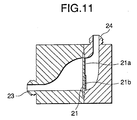
- a filter member 21 is located substantially perpendicular to filter chambers 20a and 20b,. and an ink inlet 22 is positioned higher than an outlet 23, so that the ink flows obliquely, high to low.
- an ink repellent layer 21a is formed on its upper face area, while an ink lyophilic layer 21b is formed on its lower face area.
- an inlet is located horizontally.
- an inlet 24 is located vertically in an upper area, the same effect can be obtained.
- an ink-jet recording device includes a recording head for receiving ink fed along a first ink supply path and for ejecting ink droplets; a second ink supply path along which ink is fed from an ink cartridge to the first ink supply path; and a filter member interposed at a shared area between the first ink supply path and the second ink supply path, wherein an ink lyophilic property is provided for the filter member so that an air bubble that contacts the filter material forms a contact angle that is substantially a right angle. Therefore, since the retention force of meniscuses formed at the filter member is weak, air bubbles can be easily transferred to the downstream ink flow path.
Applications Claiming Priority (3)
| Application Number | Priority Date | Filing Date | Title |
|---|---|---|---|
| JP18172697A JP3484932B2 (ja) | 1997-06-23 | 1997-06-23 | インクジェット式記録装置 |
| JP18172697 | 1997-06-23 | ||
| EP98111550A EP0887190B1 (de) | 1997-06-23 | 1998-06-23 | Tintenstrahlaufzeichnungsvorrichtung |
Related Parent Applications (2)
| Application Number | Title | Priority Date | Filing Date |
|---|---|---|---|
| EP98111550A Division EP0887190B1 (de) | 1997-06-23 | 1998-06-23 | Tintenstrahlaufzeichnungsvorrichtung |
| EP98111550.4 Division | 1998-06-23 |
Publications (3)
| Publication Number | Publication Date |
|---|---|
| EP1369247A2 true EP1369247A2 (de) | 2003-12-10 |
| EP1369247A3 EP1369247A3 (de) | 2005-11-09 |
| EP1369247B1 EP1369247B1 (de) | 2007-09-12 |
Family
ID=16105815
Family Applications (2)
| Application Number | Title | Priority Date | Filing Date |
|---|---|---|---|
| EP03020122A Expired - Lifetime EP1369247B1 (de) | 1997-06-23 | 1998-06-23 | Tintenstrahlaufzeichnungsvorrichtung |
| EP98111550A Expired - Lifetime EP0887190B1 (de) | 1997-06-23 | 1998-06-23 | Tintenstrahlaufzeichnungsvorrichtung |
Family Applications After (1)
| Application Number | Title | Priority Date | Filing Date |
|---|---|---|---|
| EP98111550A Expired - Lifetime EP0887190B1 (de) | 1997-06-23 | 1998-06-23 | Tintenstrahlaufzeichnungsvorrichtung |
Country Status (4)
| Country | Link |
|---|---|
| US (2) | US6190009B1 (de) |
| EP (2) | EP1369247B1 (de) |
| JP (1) | JP3484932B2 (de) |
| DE (2) | DE69823919T2 (de) |
Families Citing this family (40)
| Publication number | Priority date | Publication date | Assignee | Title |
|---|---|---|---|---|
| WO1999001285A1 (fr) * | 1997-07-02 | 1999-01-14 | Seiko Epson Corporation | Imprimante a jets d'encre |
| JP2878271B1 (ja) | 1998-03-27 | 1999-04-05 | 新潟日本電気株式会社 | インクジェットプリンタ記録ヘッド |
| EP0945272A3 (de) * | 1998-03-27 | 2000-01-26 | Nec Corporation | Druckkopf für einen Tintenstrahldrucker |
| JP2001001544A (ja) | 1999-06-24 | 2001-01-09 | Canon Inc | 液体供給方法、液体供給容器、負圧発生部材収納容器及び液体収納容器 |
| JP4282043B2 (ja) * | 1999-12-06 | 2009-06-17 | キヤノン株式会社 | 記録液体供給通路、記録液体収納容器、およびこれらを備える記録液体供給装置、並びにその表面改質方法 |
| JP3801003B2 (ja) | 2001-02-09 | 2006-07-26 | キヤノン株式会社 | 液体供給システム、インクジェット記録ヘッド、および液体充填方法 |
| US7198351B2 (en) | 2002-09-24 | 2007-04-03 | Brother Kogyo Kabushiki Kaisha | Ink jet recording apparatus |
| TW558516B (en) * | 2003-02-25 | 2003-10-21 | Benq Corp | Method for filling ink into inkjet cartridge |
| US7093930B2 (en) * | 2003-09-18 | 2006-08-22 | Hewlett-Packard Development Company, L.P. | Managing bubbles in a fluid-delivery device |
| JP4556699B2 (ja) * | 2005-02-15 | 2010-10-06 | セイコーエプソン株式会社 | フィルタの製造方法およびフィルタ、これを装着した液体噴射ヘッドならびに液体噴射装置 |
| JP4715247B2 (ja) * | 2005-03-10 | 2011-07-06 | 富士ゼロックス株式会社 | フィルタ装置及び液滴吐出装置 |
| JP4852861B2 (ja) * | 2005-03-30 | 2012-01-11 | セイコーエプソン株式会社 | 液体噴射ヘッドの製造方法 |
| JP4844710B2 (ja) * | 2005-03-28 | 2011-12-28 | セイコーエプソン株式会社 | フィルタの製造方法、フィルタ、及び液体噴射ヘッド |
| JP4816289B2 (ja) * | 2005-06-29 | 2011-11-16 | ブラザー工業株式会社 | 気泡捕捉装置、液体移送装置及びインクジェット記録装置 |
| US8038266B2 (en) * | 2005-06-29 | 2011-10-18 | Brother Kogyo Kabushiki Kaisha | Air bubble trapping apparatus, liquid transporting apparatus, and ink-jet recording apparatus |
| JP4292421B2 (ja) | 2006-04-27 | 2009-07-08 | セイコーエプソン株式会社 | 液体噴射ヘッド及び液体噴射装置 |
| JP4285517B2 (ja) * | 2006-09-13 | 2009-06-24 | セイコーエプソン株式会社 | 液体噴射ヘッド |
| US7954930B2 (en) * | 2006-11-30 | 2011-06-07 | Fuji Xerox Co., Ltd. | Liquid droplet ejecting head and liquid droplet ejecting apparatus |
| JP2009000729A (ja) * | 2007-06-22 | 2009-01-08 | Seiko Epson Corp | プレス加工方法、パンチングプレート、および、液体噴射ヘッド |
| US20090002469A1 (en) * | 2007-06-27 | 2009-01-01 | Seiko Epson Corporation | Liquid ejecting head and liquid ejecting apparatus |
| US8439494B2 (en) * | 2007-11-02 | 2013-05-14 | Seiko Epson Corporation | Liquid ejecting head, method for making the same, and liquid ejecting apparatus |
| JP5169261B2 (ja) * | 2008-02-01 | 2013-03-27 | セイコーエプソン株式会社 | 金属板材、フィルタ、及び金属基板の製造方法 |
| JP5472574B2 (ja) * | 2008-02-21 | 2014-04-16 | セイコーエプソン株式会社 | 液体噴射ヘッド及びその製造方法並びに液体噴射装置 |
| JP5019061B2 (ja) * | 2008-03-06 | 2012-09-05 | セイコーエプソン株式会社 | 液体噴射ヘッド及びその製造方法並びに液体噴射装置 |
| JP4670920B2 (ja) * | 2008-09-08 | 2011-04-13 | コニカミノルタホールディングス株式会社 | 記録ヘッド |
| JP5316301B2 (ja) * | 2009-08-10 | 2013-10-16 | セイコーエプソン株式会社 | 液体噴射ヘッドの製造方法 |
| JP5333026B2 (ja) * | 2009-08-10 | 2013-11-06 | セイコーエプソン株式会社 | 液体噴射ヘッドの製造方法 |
| US8523327B2 (en) * | 2010-02-25 | 2013-09-03 | Eastman Kodak Company | Printhead including port after filter |
| JP5482322B2 (ja) * | 2010-03-12 | 2014-05-07 | 株式会社リコー | 金属フィルター、それを有する画像形成装置 |
| JP2011189649A (ja) | 2010-03-15 | 2011-09-29 | Seiko Epson Corp | 液体噴射ヘッド及び液体噴射装置 |
| JP2013116564A (ja) | 2011-12-01 | 2013-06-13 | Seiko Epson Corp | 液体噴射ヘッド |
| JP5661838B2 (ja) * | 2012-04-25 | 2015-01-28 | キヤノンファインテック株式会社 | インク供給装置および記録装置 |
| JP6160028B2 (ja) * | 2012-05-07 | 2017-07-12 | 株式会社リコー | インクジェット装置、インク、インク供給ユニットおよびインクジェット記録方法 |
| JP6263879B2 (ja) * | 2013-07-09 | 2018-01-24 | セイコーエプソン株式会社 | 液体噴射装置 |
| US10603922B2 (en) | 2015-01-22 | 2020-03-31 | Hewlett-Packard Development Company, L.P. | Vent |
| JP7003370B2 (ja) * | 2017-07-21 | 2022-01-20 | 東芝テック株式会社 | 液滴吐出装置及びインクジェットプリンタ |
| TWI800523B (zh) | 2017-08-14 | 2023-05-01 | 美商偉斯特洛克包裝系統有限責任公司 | 物品攜具及其胚片 |
| JP6631666B2 (ja) * | 2018-08-09 | 2020-01-15 | 株式会社リコー | インクジェット装置、インクジェット記録方法およびインク |
| JP2022040498A (ja) | 2020-08-31 | 2022-03-11 | セイコーエプソン株式会社 | 液体吐出装置、ヘッド駆動回路、及び液体吐出ヘッド |
| JP2022000338A (ja) * | 2020-06-17 | 2022-01-04 | セイコーエプソン株式会社 | 流路部材、液体噴射ヘッド、液体噴射装置、および流路部材の製造方法 |
Citations (3)
| Publication number | Priority date | Publication date | Assignee | Title |
|---|---|---|---|---|
| JPS57157765A (en) | 1981-03-25 | 1982-09-29 | Fujitsu Ltd | Nozzle plate for ink jet print head |
| JPS60183161A (ja) | 1984-02-29 | 1985-09-18 | Fujitsu Ltd | インクジエツトヘツドの撥水処理方法 |
| JPH07205428A (ja) | 1994-01-20 | 1995-08-08 | Seiko Epson Corp | インクジェット記録ヘッド及びその製造方法 |
Family Cites Families (10)
| Publication number | Priority date | Publication date | Assignee | Title |
|---|---|---|---|---|
| JPS5689569A (en) | 1979-12-19 | 1981-07-20 | Canon Inc | Ink jet recording head |
| US4719479A (en) * | 1983-04-22 | 1988-01-12 | Canon Kabushiki Kaisha | Bundled-tube filter for recording apparatus |
| JPS6137435A (ja) * | 1984-07-31 | 1986-02-22 | Canon Inc | 液体噴射記録装置 |
| US5182581A (en) * | 1988-07-26 | 1993-01-26 | Canon Kabushiki Kaisha | Ink jet recording unit having an ink tank section containing porous material and a recording head section |
| US5365261A (en) * | 1992-03-19 | 1994-11-15 | Seiko Epson Corporation | Transfer type ink jet printer |
| JPH06286150A (ja) * | 1993-04-02 | 1994-10-11 | Citizen Watch Co Ltd | インクジェットプリンターヘッドの製造方法 |
| JPH06340071A (ja) * | 1993-06-01 | 1994-12-13 | Sharp Corp | インキジェットプリンタの記録ヘッド、およびその製造方法ならびにインキジェットプリンタ |
| JP3168122B2 (ja) | 1993-09-03 | 2001-05-21 | キヤノン株式会社 | インクジェットヘッド及び該インクジェットヘッドを備えたインクジェット記録装置 |
| JP3821498B2 (ja) | 1995-01-23 | 2006-09-13 | セイコーエプソン株式会社 | インクジェット式記録ユニット、及びインクカートリッジ |
| JP3713632B2 (ja) * | 1994-12-28 | 2005-11-09 | 富士写真フイルム株式会社 | インクカートリッジ、及びインクジェットプリンタ |
-
1997
- 1997-06-23 JP JP18172697A patent/JP3484932B2/ja not_active Expired - Fee Related
-
1998
- 1998-06-23 DE DE69823919T patent/DE69823919T2/de not_active Expired - Lifetime
- 1998-06-23 EP EP03020122A patent/EP1369247B1/de not_active Expired - Lifetime
- 1998-06-23 US US09/102,915 patent/US6190009B1/en not_active Expired - Fee Related
- 1998-06-23 EP EP98111550A patent/EP0887190B1/de not_active Expired - Lifetime
- 1998-06-23 DE DE69838438T patent/DE69838438D1/de not_active Expired - Lifetime
-
2000
- 2000-09-22 US US09/667,632 patent/US6338554B1/en not_active Expired - Fee Related
Patent Citations (3)
| Publication number | Priority date | Publication date | Assignee | Title |
|---|---|---|---|---|
| JPS57157765A (en) | 1981-03-25 | 1982-09-29 | Fujitsu Ltd | Nozzle plate for ink jet print head |
| JPS60183161A (ja) | 1984-02-29 | 1985-09-18 | Fujitsu Ltd | インクジエツトヘツドの撥水処理方法 |
| JPH07205428A (ja) | 1994-01-20 | 1995-08-08 | Seiko Epson Corp | インクジェット記録ヘッド及びその製造方法 |
Also Published As
| Publication number | Publication date |
|---|---|
| EP0887190A2 (de) | 1998-12-30 |
| EP1369247B1 (de) | 2007-09-12 |
| US6338554B1 (en) | 2002-01-15 |
| EP0887190B1 (de) | 2004-05-19 |
| JP3484932B2 (ja) | 2004-01-06 |
| EP0887190A3 (de) | 1999-09-15 |
| DE69838438D1 (de) | 2007-10-25 |
| EP1369247A3 (de) | 2005-11-09 |
| JPH1110904A (ja) | 1999-01-19 |
| US6190009B1 (en) | 2001-02-20 |
| DE69823919D1 (de) | 2004-06-24 |
| DE69823919T2 (de) | 2005-06-30 |
Similar Documents
| Publication | Publication Date | Title |
|---|---|---|
| EP0887190B1 (de) | Tintenstrahlaufzeichnungsvorrichtung | |
| JP4141523B2 (ja) | インク供給流路の弁装置 | |
| US6916090B2 (en) | Integrated fluid ejection device and filter | |
| US6582064B2 (en) | Fluid ejection device having an integrated filter and method of manufacture | |
| US20080259146A1 (en) | Ink-jet recording head and method for manufacturing ink-jet recording head | |
| KR20060082412A (ko) | 액체 토출 헤드, 액체 토출 장치 및 액체 토출 헤드의 제조방법 | |
| WO2008029650A1 (en) | Liquid discharge head and method of manufacturing the same | |
| KR20070009728A (ko) | 길게 연장된 필터 어셈블리 | |
| JP3420272B2 (ja) | インクジェットプリントヘッドにおける飛沫キャッチャー装置 | |
| KR20020069172A (ko) | 잉크 제트 헤드, 그 제조 방법 및 잉크 제트 기록 장치 | |
| JP4414213B2 (ja) | インクジェット印刷システム | |
| US20060044353A1 (en) | Liquid discharge head and method of manufacturing the same | |
| JPH11291513A (ja) | インクジェット式記録装置 | |
| JP2002137410A (ja) | 液体吐出記録ヘッド | |
| JP2013520341A (ja) | フィルタの後にポートを含むプリントヘッド | |
| JP3552024B2 (ja) | インクジェット式記録ヘッド | |
| JP2012250484A (ja) | 液滴吐出ヘッド及び画像形成装置 | |
| JPS63252749A (ja) | インクオンデマント型のインクジエツトヘツド | |
| JP2000218827A (ja) | 印刷ヘッドからの流体除去方法 | |
| EP1334833B1 (de) | Wartungsmodul für eine Flüssigheitsstrahlvorrichtung und diese Flüssigheitsstrahlvorrichtung | |
| JPH10193612A (ja) | インクジェット式記録ヘッド | |
| JPS58112748A (ja) | インクジエツトヘツド | |
| JPH11157060A (ja) | インクジェットヘッド | |
| JP3820744B2 (ja) | インクジェット式記録装置 | |
| JPH1170671A (ja) | インクジェットカートリッジ及びその製造方法 |
Legal Events
| Date | Code | Title | Description |
|---|---|---|---|
| PUAI | Public reference made under article 153(3) epc to a published international application that has entered the european phase |
Free format text: ORIGINAL CODE: 0009012 |
|
| 17P | Request for examination filed |
Effective date: 20030904 |
|
| AC | Divisional application: reference to earlier application |
Ref document number: 0887190 Country of ref document: EP Kind code of ref document: P |
|
| AK | Designated contracting states |
Kind code of ref document: A2 Designated state(s): DE FR GB IT |
|
| PUAL | Search report despatched |
Free format text: ORIGINAL CODE: 0009013 |
|
| AK | Designated contracting states |
Kind code of ref document: A3 Designated state(s): DE FR GB IT |
|
| RIC1 | Information provided on ipc code assigned before grant |
Ipc: 7B 41J 2/175 B Ipc: 7B 41J 2/19 A |
|
| AKX | Designation fees paid |
Designated state(s): DE FR GB IT |
|
| 17Q | First examination report despatched |
Effective date: 20060801 |
|
| GRAP | Despatch of communication of intention to grant a patent |
Free format text: ORIGINAL CODE: EPIDOSNIGR1 |
|
| GRAS | Grant fee paid |
Free format text: ORIGINAL CODE: EPIDOSNIGR3 |
|
| GRAA | (expected) grant |
Free format text: ORIGINAL CODE: 0009210 |
|
| AC | Divisional application: reference to earlier application |
Ref document number: 0887190 Country of ref document: EP Kind code of ref document: P |
|
| AK | Designated contracting states |
Kind code of ref document: B1 Designated state(s): DE FR GB IT |
|
| REG | Reference to a national code |
Ref country code: GB Ref legal event code: FG4D |
|
| REF | Corresponds to: |
Ref document number: 69838438 Country of ref document: DE Date of ref document: 20071025 Kind code of ref document: P |
|
| PLBE | No opposition filed within time limit |
Free format text: ORIGINAL CODE: 0009261 |
|
| STAA | Information on the status of an ep patent application or granted ep patent |
Free format text: STATUS: NO OPPOSITION FILED WITHIN TIME LIMIT |
|
| PG25 | Lapsed in a contracting state [announced via postgrant information from national office to epo] |
Ref country code: DE Free format text: LAPSE BECAUSE OF FAILURE TO SUBMIT A TRANSLATION OF THE DESCRIPTION OR TO PAY THE FEE WITHIN THE PRESCRIBED TIME-LIMIT Effective date: 20071213 |
|
| 26N | No opposition filed |
Effective date: 20080613 |
|
| PG25 | Lapsed in a contracting state [announced via postgrant information from national office to epo] |
Ref country code: IT Free format text: LAPSE BECAUSE OF NON-PAYMENT OF DUE FEES Effective date: 20080630 |
|
| PGFP | Annual fee paid to national office [announced via postgrant information from national office to epo] |
Ref country code: GB Payment date: 20110622 Year of fee payment: 14 |
|
| GBPC | Gb: european patent ceased through non-payment of renewal fee |
Effective date: 20120623 |
|
| PG25 | Lapsed in a contracting state [announced via postgrant information from national office to epo] |
Ref country code: GB Free format text: LAPSE BECAUSE OF NON-PAYMENT OF DUE FEES Effective date: 20120623 |
|
| PG25 | Lapsed in a contracting state [announced via postgrant information from national office to epo] |
Ref country code: FR Free format text: LAPSE BECAUSE OF FAILURE TO SUBMIT A TRANSLATION OF THE DESCRIPTION OR TO PAY THE FEE WITHIN THE PRESCRIBED TIME-LIMIT Effective date: 20070912 |