EP1362734A1 - Dispositif de commutation d'etat pour vehicule - Google Patents
Dispositif de commutation d'etat pour vehicule Download PDFInfo
- Publication number
- EP1362734A1 EP1362734A1 EP01967745A EP01967745A EP1362734A1 EP 1362734 A1 EP1362734 A1 EP 1362734A1 EP 01967745 A EP01967745 A EP 01967745A EP 01967745 A EP01967745 A EP 01967745A EP 1362734 A1 EP1362734 A1 EP 1362734A1
- Authority
- EP
- European Patent Office
- Prior art keywords
- shift
- dial
- rotational
- over device
- status change
- Prior art date
- Legal status (The legal status is an assumption and is not a legal conclusion. Google has not performed a legal analysis and makes no representation as to the accuracy of the status listed.)
- Granted
Links
- 230000033001 locomotion Effects 0.000 claims abstract description 26
- 230000005540 biological transmission Effects 0.000 claims description 16
- 238000010586 diagram Methods 0.000 description 7
- 150000001875 compounds Chemical class 0.000 description 3
- 230000000994 depressogenic effect Effects 0.000 description 3
- 230000035515 penetration Effects 0.000 description 2
- 230000002093 peripheral effect Effects 0.000 description 2
- 238000012986 modification Methods 0.000 description 1
- 230000004048 modification Effects 0.000 description 1
Images


Classifications
-
- B60K35/10—
-
- B—PERFORMING OPERATIONS; TRANSPORTING
- B60—VEHICLES IN GENERAL
- B60K—ARRANGEMENT OR MOUNTING OF PROPULSION UNITS OR OF TRANSMISSIONS IN VEHICLES; ARRANGEMENT OR MOUNTING OF PLURAL DIVERSE PRIME-MOVERS IN VEHICLES; AUXILIARY DRIVES FOR VEHICLES; INSTRUMENTATION OR DASHBOARDS FOR VEHICLES; ARRANGEMENTS IN CONNECTION WITH COOLING, AIR INTAKE, GAS EXHAUST OR FUEL SUPPLY OF PROPULSION UNITS IN VEHICLES
- B60K20/00—Arrangement or mounting of change-speed gearing control devices in vehicles
- B60K20/02—Arrangement or mounting of change-speed gearing control devices in vehicles of initiating means
- B60K20/06—Arrangement or mounting of change-speed gearing control devices in vehicles of initiating means mounted on steering column or the like
-
- F—MECHANICAL ENGINEERING; LIGHTING; HEATING; WEAPONS; BLASTING
- F16—ENGINEERING ELEMENTS AND UNITS; GENERAL MEASURES FOR PRODUCING AND MAINTAINING EFFECTIVE FUNCTIONING OF MACHINES OR INSTALLATIONS; THERMAL INSULATION IN GENERAL
- F16H—GEARING
- F16H59/00—Control inputs to control units of change-speed-, or reversing-gearings for conveying rotary motion
- F16H59/02—Selector apparatus
- F16H59/08—Range selector apparatus
- F16H59/10—Range selector apparatus comprising levers
- F16H59/105—Range selector apparatus comprising levers consisting of electrical switches or sensors
-
- F—MECHANICAL ENGINEERING; LIGHTING; HEATING; WEAPONS; BLASTING
- F16—ENGINEERING ELEMENTS AND UNITS; GENERAL MEASURES FOR PRODUCING AND MAINTAINING EFFECTIVE FUNCTIONING OF MACHINES OR INSTALLATIONS; THERMAL INSULATION IN GENERAL
- F16H—GEARING
- F16H61/00—Control functions within control units of change-speed- or reversing-gearings for conveying rotary motion ; Control of exclusively fluid gearing, friction gearing, gearings with endless flexible members or other particular types of gearing
- F16H61/22—Locking of the control input devices
-
- B60K2360/126—
-
- F—MECHANICAL ENGINEERING; LIGHTING; HEATING; WEAPONS; BLASTING
- F16—ENGINEERING ELEMENTS AND UNITS; GENERAL MEASURES FOR PRODUCING AND MAINTAINING EFFECTIVE FUNCTIONING OF MACHINES OR INSTALLATIONS; THERMAL INSULATION IN GENERAL
- F16H—GEARING
- F16H59/00—Control inputs to control units of change-speed-, or reversing-gearings for conveying rotary motion
- F16H59/02—Selector apparatus
- F16H59/08—Range selector apparatus
- F16H2059/081—Range selector apparatus using knops or discs for rotary range selection
Definitions
- the present invention relates to a vehicle status change-over device having at least shift position switch for a vehicle.
- the present invention has been completed with a view to addressing an issue set forth above and has an object to provide a vehicle status change-over device which is easy to operate and has an increased degree of freedom in a layout of a shift operating section of the vehicle status change-over device.
- a vehicle status change-over device comprising a rotational member rotatable about a center of a given rotational axis, an ignition switch operative to select at least an engine start-up interruptive status and an engine start-up permit status in dependence on a rotational position of the rotational member, a dial located for rotational movement about a center on the substantially same line as a rotational center of the rotational member, and a shift position switch selecting a shift position of a power transmission in dependence on a rotational position of the dial.
- a vehicle status change-over device comprising a dial disposed for rotational movement, a shift position switch selecting a shift position of a power transmission in dependence on a rotational position of the dial, a second shift lock section operative to prevent the dial from being rotated to retain the shift position switch in an off position and to release the off position of the shift position switch when ID information of an electronic key coincides with given ID information, and an engine control unit operative to start up an engine when the shift position switch assumes a parking position.
- the first aspect of the present invention provides a vehicle status change-over device comprising a rotational member rotatable about a center of a given rotational axis, an ignition switch operative to select at least an engine start-up interruptive status and an engine start-up permit status in dependence on a rotational position of the rotational member, a dial located for rotational movement about a center on the substantially same line as a rotational center of the rotational member, and shift position selecting means for selecting a shift position of a power transmission in dependence on a rotational position of the dial.
- the second aspect of the present invention provides a vehicle status change-over device comprising a dial located for rotational movement, shift position selecting means for selecting a shift position of a power transmission in dependence on a rotational position of the dial, second shift lock section means operative to prevent the dial from being rotated to retain the shift position switch in an off position and to release the off position of the shift position switch when ID information of an electronic key coincides with given ID information, and engine control means operative to start up an engine when the shift position selection means assumes a parking position.
- FIG. 1 is a perspective view of a vehicle status change-over device according to the present invention.
- FIG. 2 is a view illustrating a part of the vehicle status change-over device shown in FIG. 1.
- FIG. 3 is a view illustrating apart of the vehicle status change-over device shown in FIG. 1.
- FIG. 4 is a half cross sectional view illustrating a first embodiment of the vehicle status change-over device according to the present invention.
- FIGS. 1 to 4 fixed to a steering column cover 2 of a steering wheel 1 are an ignition key switch 4 and a substantially cylindrical key cylinder case 3.
- the key cylinder case 5 encompasses a rotator (rotational member) 6 of a key cylinder.
- the rotator 6 is supported in the case 5 for rotational movement about a given rotational axis and connected to the ignition switch 4. Further, a distal end face (at a rightward end in a sheet of FIG. 4) is placed with a ring shaped display segment 7.
- the display segment 7 is fixed to the case 7 at areas which are not shown with it's front face is provided with a display of "OFF", "ACC", "ON” and "ST".
- the ignition switch 4, the case 5, the rotator 6 and the display segment 7 form an ignition switch device 3.
- the ignition switch 4 When an ignition key (not shown) inserted to a key hole of the rotator 6 remains in the "OFF" display position, the ignition switch 4 assumes an “OFF" position (an engine start-up interruptive status) with a battery power supply being disconnected with either one of an ignition (IGN) contact, an accessory (ACC) contact and a start (ST) contact. And, when the ignition key remains in the “ACC” display position, the ignition switch 4 assumes the “ACC” position with the battery power supply being connected to the accessory contact. Further, when the ignition key remains in the "ON” display position, the ignition switch 4 assumes an “ON” position (engine start up permit status) with the battery power supply being connected to. the ignition contact and the accessory contact.
- the ignition switch 4 assumes an "ST" position with the battery power supply being connected to the ignition contact and the start contact. That is, the ignition switch 4 is operative to select at least the engine start-up interruptive status and the engine start-up permit status in dependence on a rotational angular position of the rotator 6. Furthermore, a shift position switch 8 is held stationary in the case 5. And, a cylindrical shaped dial 9 is mounted in the case 5 for rotational movement about an axis approximately coincident with a rotational center of the rotator 6. Also, the dial 9 is disposed in the case 5 and connected to the shift position switch 8.
- the shift position switch 8 and the dial 9 form a shift operating section of a vehicle shift change-over device
- the shift position switch 8 is operative to select a shift position of a power transmission in dependence on a rotational position of the dial 9.
- a distal end (at a rightward end in the sheet of FIG. 4) is formed with a cylindrical shaped rotational operator segment 9a in a way to assume an outward position of the case 5.
- a distal end portion, closer to the steering column cover 2 (at a leftward position in a sheet of FIG. 3), of an outer peripheral surface of the rotational operator segment 9a is provided with displays of "P" , "R” , etc. indicative of shift positions.
- an outer periphery of the dial 9 is provided with a display of a triangle symbol at a position opposing to the above display. And, an outer periphery of the dial 9 is formed with a bore 10 with its central axis extending in a radial direction (in a vertical direction in the sheet of FIG. 4). Further, a spring 11 and a ball 12 are disposed in the bore 10. Furthermore, a plurality of concave portions 13 are formed on an inner periphery of the case 3 at circumferentially spaced positions corresponding to the above display of the rotational operator segment 9a.
- the ball 12 is operative to engage one of the concave portions 13 and, when the ball 12 engages the concave portion 13, selected one of the above displays of "P", "R”, etc. of the rotational operator segment 9a is positioned in opposed relation to the above described triangle symbol.
- the spring 11, the ball 12 and the plural concave portions 13 form a positioning section of the dial 9.
- the outer periphery of the dial 9 is formed with a bore 14.
- a shift lock solenoid 15 is mounted to the case 5 at an area corresponding to the bore 14 when the shift position switch 8, disposed inside the case 5, assumes the "P" position (parking position), and a lock pin 16 is inserted through the case 5 to be movable with the shift lock solenoid 15.
- the bore 14, the shift lock solenoid 15 and the lock pin 16 form a first shift lock section to preclude the dial 9 from being rotated in a case where the ignition switch 4 is selected in the engine start-up interruptive status.
- the lock pin 16 is not attracted with the shift lock solenoid 15.
- the outer periphery of the case 5 is placed with an indicator 17 of the vehicle shift change-over device with the indicator 17 being provided with displays of "P", "R", etc. and photo diodes are located in opposed positions of the displays of "P", "R”, etc.
- FIG. 6 is a circuit diagram of the vehicle status change-over device shown in FIGS. 1 to 4.
- an input interface 18 connected to an input interface 18 are the ignition switch 4, the shift position switch 8 and a computing section (microcomputer) 19.
- a shift lock solenoid output circuit 20, an actuator output circuit 21 and an indicator output circuit 22 are connected to the computing section 19.
- the shift lock solenoid output circuit 20 is connected to the shift lock solenoid 15.
- the actuator output circuit 21 is a shift change-over actuator 24.
- connected to the indicator output circuit 22 is the photo diode of the indicator 17.
- the input interface 18, the computing section 19, the shift lock solenoid output circuit 20, the actuator output circuit 21 and the indicator output circuit 22 form a shift control unit 23a.
- the rotation of the rotator 6 of the key cylinder enables the engine to be started up, and the rotation of the dial 9, which is substantially positioned in alignment with the rotational center of the rotator 6, enables the shift to be changed over in the power transmission.
- the rotation of the dial 9 which is substantially positioned in alignment with the rotational center of the rotator 6, enables the shift to be changed over in the power transmission.
- the dial 9 is rotated to enable the shift of the power transmission to be changed over, no space for parallel movement of the ignition key is required, resulting in an increased degree of freedom for a layout of the shift operating section of the vehicle shift change-over device. Also, the presence of the first shift lock section disabling the rotation of the dial 9, when the ignition switch 4 assumes the "OFF" position and "ACC" position, provides a capability of preventing the dial 9 from being erroneously operated.
- FIG. 7 is a half cross sectional view illustrating a second embodiment of a vehicle status change-over device according to the present invention.
- a first rotator 31 is disposed in the case 5 of the key cylinder.
- the first rotator 31 is supported with the case 5 of the key cylinder for rotational movement and connected to the ignition switch 4.
- a second rotator 32 of the key cylinder is supported with the dial 9 for rotational movement.
- the second rotator 32 is connected to the first rotator 31 in such a way that the second rotator 17 is relatively moveable along an axial direction (leftward and rightward direction in a sheet of FIG.
- a spring 33 is disposed between the dial 9 and the second rotator 32.
- the dial 9 is formed with a sector slit penetration 34 extending perpendicular to the center line.
- an outer periphery of the second rotator 32 is formed with a bore 35.
- a push lock solenoid 36 is mounted at an area corresponding to the slit penetration 34 of the outer periphery of the case 5, and a lock pin 37 adapted to be moveable with the push lock solenoid 36 is provided.
- the bore 35, the push lock solenoid 36 and the lock pin 37 form a push lock section (retainer section) which is operative to retain a rear end of the second rotator 32 in a retracted position when the shift position switch 8 assumes the position except the "P" position and to be released when the shift position switch 8 assumes the "P” position.
- the lock pin 37 is attracted with the push lock solenoid 36 .
- the vehicle status change-over device of the presently filed embodiment includes the first shift lock section like in the embodiment shown in FIGS. 1 to 4.
- FIG. 9 is a circuit diagram of the vehicle status change-over device shown in FIG. 7. As shown in FIG. 9, connected to the computing section 19 is a push lock solenoid output circuit 39. Further, connected to the push lock solenoid output circuit 39 is the push lock solenoid 36. And, the input interface 18, the computing section 19, the shift lock solenoid output circuit 20, the push lock solenoid output circuit 39, the actuator output circuit 21 and the indicator output circuit 22 form a shift control unit 23b.
- the first rotator 31 is connected to the ignition switch 4 .
- the second rotator 32 is connected to the first rotator 31 to be disabled for relative rotation. Accordingly, if the second rotator 32 is rotated with the ignition key 38, then, it is possible to change over the ignition switch 4. And, as shown in FIG. 7, when the shift position switch 8 assumes the "P" position, the lock pin 37 is attracted with the push lock solenoid 36. Consequently, even if the second rotator 23 is depressed (moved leftward in a sheet of FIG. 7), the lock pin 37 is out of engagement with the bore 35. Further, as shown in FIG.
- the lock pin 37 disengages the bore 35 to allow the second rotator 32 to be depressed with the spring 33 to cause the second rotator 32 to restore the position shown in FIG. 7, thereby enabling the ignition key 38 to be operated.
- the retaining section is released when the shift position switch 8 assumes the "P" position.
- FIG. 10 is a half cross sectional view illustrating a third embodiment of a vehicle status change-over device according to the present invention.
- FIG. 11 is a view illustrating a portion of the vehicle status change-over device shown in FIG. 10.
- a substantially cylindrical shaped case 41 is fixed to the steering column cover 2 (see FIG. 1).
- a shift position switch 42 is fixed to the case 41.
- a dial 43 is mounted to the case 41.
- the case 41 serving as a support member supports the cylindrical dial (rotational operation knob) 43 for rotational movement thereof and is connected to a shift position switch 42.
- the shift position switch 42 and the dial 43 form a shift operating section of the vehicle status change-over device.
- the shift position switch 42 is operative to select the shift position of the power transmission in dependence on the rotational position of the dial 43.
- a distal end (rightward end portion in a sheet of FIG. 11) of the dial 43 is formed with a rotational operator segment 43a, which is located outside the case 41.
- a distal end portion, closer to the steering column cover 2 (at a leftward position in a sheet of FIG. 11), of an outer peripheral surface of the rotational operator segment 43a is provided with displays of "OFF" , "P" , "R” , etc. indicative of the shift positions.
- an outer periphery of the case 41 is provided with a display of a triangle symbol at a position opposing to the above display of the rotational operator segment 43a.
- the outer periphery of the case 41 is placed with an indicator 51 of the vehicle shift change-over device.
- the indicator 51 is provided with displays of "OFF” , "P” , “R” , etc. and photo diodes are located in opposed positions of the displays of "OFF", "P", "R”, etc.
- an outer periphery of the dial 43 is formed with a bore 44 with its center line extending in a radial direction (vertical direction in a sheet of FIG. 10).
- a spring 45 and a ball 46 are inserted in the bore 44 .
- a plurality of convex portions 47 are formed on an inner periphery of the case 41 at positions corresponding to the above described display.
- the ball 46 engages one of the convex portions 47 and, when the ball engages the convex portion 47, selected one of "P", "R”, etc. displays of the rotational operator segment 43a is positioned at an area opposing to the triangle symbol set forth above.
- the spring 45, the ball 46 and the plural convex portions 47 form a positioning section of the dial 43.
- the outer periphery of the dial 43 is formed with a bore 48.
- a shift lock solenoid 49 is mounted to the outer periphery of the case 41 at an area corresponding to the bore 48 when the shift position switch 42 assumes the "OFF" position (off position), and a lock pin 50 is inserted through the case 41 to be moveable with the shift lock solenoid 49. Also, as shown in FIG.
- the dial 43 under a condition where the lock pin 50 is not attracted with the shift lock solenoid 49, the dial 43 is enabled to slightly rotate.
- the bore 48, the shift lock solenoid 49 and the lock pin 50 form a second shift lock section that precludes the rotation of the dial 43 to retain the shift position switch 42 in an off position and when ID information of an electronic card key is aligned with given ID information, the retaining of the off position is released.
- FIG. 12 is a view illustrating the relationship between the dial position of the vehicle status change-over device shown in FIGS. 10 and 11 and output signals of the shift position switch.
- the shift position switch 42 is inoperative to produce the position signals. Also, when the dial 43 is slightly rotated with the shift position switch 42 remaining in the "OFF” position, the shift position switch 42 is operative to produce an inquiry start signal.
- FIG. 13 is a circuit diagram of the vehicle status change-over device shown in FIG. 11.
- a shift control unit 61 is connected to the shift position switch 42, the shift lock solenoid 49, the indicator 51, a shift change-over actuator 62, an ID inquiry device 63 and an engine control 64.
- the inquiry start signal is outputted from the shift position switch 42, and when an electronic card key (with a communicating function) is placed within a given distance from the ID inquiry device 63, the ID inquiry device 63 is operative to read out the ID information from the electronic card key.
- the operation is executed to discriminate whether or not the read out ID information is in coincidence with given ID information, and when the read out ID information coincides with the given ID information, a rotation available signal is outputted to the shift control unit 61. Further, when the rotation available signal is outputted from the ID inquiry device 63, the shift control unit 61 operates the shift lock solenoid 4 9 . That is, as shown in FIG. 10, when the rotation available signal is not outputted from the ID inquiry device 63, the lock pin 50 is not attracted with the shift lock solenoid 49. In contrast, as shown in FIG. 14, when the rotation available signal is outputted from the inquiry device 63, the lock pin 50 is attracted with the shift lock solenoid 49.
- the shift control unit 61 outputs an engine start-up signal to the engine control unit 64. And, when the engine control unit 64 receives the engine start-up signal from the shift control unit 61, the engine control unit 64 is operative to start up the engine (not shown).
- the operation of the vehicle status change-over device shown in FIGS. 10 to 13 is described below with reference to FIG. 15.
- the inquiry start signal is outputted from the shift position switch 42.
- the ID inquiry device 63 reads out the ID information from the electronic card key, and discrimination is made as to whether or not the read out ID information coincides with the given ID information which is preliminarily stored.
- the rotation available signal is outputted to the shift control unit 61.
- the lock pin 50 is attracted with the shift lock solenoid 49 and, hence, the driver is enabled to freely rotate the dial 43.
- the shift position switch 42 comes to assume the "P” position. And, the shift control unit 61 outputs the engine start-up signal to the engine control unit 64, causing the engine control unit 64 to start up he engine. Under such a condition, as the driver rotates the dial 43 from the "P" position to the "D” position, the shift position switch 42 assumes the "D” position, enabling the vehicle to move forward. On the contrary, if the read out ID information is out of coincidence with the given ID information, the rotation available signal is not outputted to the shift control unit 61 and, as shown in FIG. 10, the lock pin 50 remains in the condition where it is not attracted with the shift lock solenoid 49 . Accordingly, the driver is disenabled to rotate the dial 43, resulting in an inability of starting up the engine.
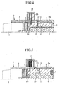
- FIG. 16 is a half cross sectional view illustrating a fourth embodiment of a vehicle status change-over device according to the present invention.
- FIG. 17 is a view illustrating a portion of the vehicle status change-over device shown in FIG. 16.
- the outer periphery of the dial 43 is formed with a bore 71.
- a shift lock solenoid 72 is mounted to the outer periphery of the case 41 at an area corresponding to the bore 71 when the shift position switch 42 assumes the "P" position, and a lock pin 73 is inserted through the case 41 to be moveable with the shift lock solenoid 72.
- FIG. 16 is a half cross sectional view illustrating a fourth embodiment of a vehicle status change-over device according to the present invention.
- FIG. 17 is a view illustrating a portion of the vehicle status change-over device shown in FIG. 16.
- the outer periphery of the dial 43 is formed with a bore 71.
- a shift lock solenoid 72 is mounted to the outer peripher
- the dial 43 is enabled to rotate from the "OFF" position to the "P" display position. Further, when the engine control unit 64 starts up the engine and the rotational speed of the engine exceeds a given value, an engine start-up completion signal is outputted from the engine control unit 64 to the shift control unit 61. Also, the shift lock solenoid 72 is connected to the shift control unit 61, and when the engine start-up completion signal is outputted from the engine control unit 64, the shift control unit 61 operates the shift lock solenoid 72. That is, as shown in FIG.
- the lock pin 73 is not attracted with the shift lock solenoid 72.
- the lock pin 73 is attracted with the shift lock solenoid 72.
- the bore 71, the shift lock solenoid 72 and the lock pin 73 form a shift lock section that precludes the rotation of the dial 43 in a case where the engine rotational speed does not exceed the given value.
- the presently filed embodiment also includes the second shift lock section like in the embodiment of FIGS. 10 to 14.
- the operation of the vehicle status change-over device shown in FIGS. 16 and 17 is described below with reference to FIG. 19.
- the ID inquiry device 63 reads out the ID information from the electronic card key, and discrimination is made as to whether or not the read out ID information coincides with the given ID information which is preliminarily stored. And, when the read out ID information coincides with the given ID information, the rotation available signal is outputted to the shift control unit 61. Then, as shown in FIG. 14, the lock pin 50 is attracted with the shift lock solenoid 49 and, hence, the driver is enabled to rotate the dial 43 to the "P" display position.
- the driver is able to freely rotate the dial 43 and, under such condition, if the driver rotates the dial 43 from the "P" display position to the "D" display position, the shift position switch 42 assumes the "D" position, enabling the vehicle to move forward.
- the lock pin 50 remains in the condition in which it is not attracted with the shift lock solenoid 49 as shown in FIG. 10, resulting in an inability for the driver to rotate the dial 43 with a resultant difficulty in starting up the engine.
- the shift position switch 42 is enabled to be located in a drive position such as the "D" position. That is, since the shift position switch 42 is rotated from the “OFF” position to the "P" position and, after the engine has been completely started up, the shift position switch 42 is moveable from the "P" position to the "R” position, it is possible to preclude the operation of the engine from being interrupted during the start-up operation of the engine.
- the rotator includes the rotational member to allow the ignition key to be inserted to the key hole of the rotator of the key cylinder to rotate the same for thereby starting up the engine
- a technology is known in which such a mechanical key is not in use and an ID inquiry is made between the electronic card key carried by an occupant and an associated ID inquiry device installed in the vehicle to discriminate a proper owner when an inquiry result is obtained in coincidence for thereby allowing the rotational operating knob of the vehicle to be rotated to allow the engine to be rotated, the presence of the rotational operating knob and a portion, rotational with accompanying rotation of the rotational operating knob, which are composed of the rotational member enables the present invention to be applied such a device.
- the ignition key 38 has been shown as being completely accommodated in the case 5, it is needless to say that the ignition key need not be completely accommodated in the case.
- the electronic key has been described as employing the electronic card key, other electronic keys may be employed.
- rotation of the rotational member enables the engine to be started up and rotation of the rotational member rotatable about the center substantially aligned with the rotational center of the rotational member enables the shift position to be selected.
- the rotation of the dial since it is possible to perform the operation, before beginning the travel of the vehicle between the start-up of the engine and the selecting operation of the shift position, with the single hand in one identical operation, it is easy to implement the operation.
- the rotation of the dial enables the shift of the power transmission to be changed over, there is no need for the space for the parallel movement of the ignition key, resulting in the increased degree of freedom in the layout of the shift operating section of the vehicle status change-over device.
- the shift position switch in an event that the shift position switch assumes the position except for the parking position, since the rotational member has the retaining section that holds the side wall, closer to the vehicle compartment, of the rotational member in the retracted position, when rotating the dial, disposed around the periphery of the rotational member, after start-up of the engine by rotating the rotational member, the operation is not interrupted with the key inserted to the rotational member, resulting in a capability for the operation to be smoothly performed.
- the rotational member since the retaining section is released when the shift position switch assumes the parking position to permit the position of the rotational member to be restored to the original position, it is possible for the rotational member to smoothly select the operation of the engine start-up interruptive condition.
- the shift position switch is enabled to assume the drive position only when the engine rotational speed exceeds the given value, it is possible to preclude the engine from being halted during the engine start-up.
Landscapes
- Engineering & Computer Science (AREA)
- General Engineering & Computer Science (AREA)
- Mechanical Engineering (AREA)
- Chemical & Material Sciences (AREA)
- Combustion & Propulsion (AREA)
- Transportation (AREA)
- Arrangement Or Mounting Of Control Devices For Change-Speed Gearing (AREA)
- Control Of Transmission Device (AREA)
- Steering Controls (AREA)
Applications Claiming Priority (3)
| Application Number | Priority Date | Filing Date | Title |
|---|---|---|---|
| JP2001042994A JP3873633B2 (ja) | 2000-03-24 | 2001-02-20 | 車両用状態切り替え装置 |
| JP2001042994 | 2001-02-20 | ||
| PCT/JP2001/008178 WO2002066279A1 (fr) | 2001-02-20 | 2001-09-20 | Dispositif de commutation d'etat pour vehicule |
Publications (3)
| Publication Number | Publication Date |
|---|---|
| EP1362734A1 true EP1362734A1 (fr) | 2003-11-19 |
| EP1362734A4 EP1362734A4 (fr) | 2004-12-29 |
| EP1362734B1 EP1362734B1 (fr) | 2007-04-25 |
Family
ID=18905227
Family Applications (1)
| Application Number | Title | Priority Date | Filing Date |
|---|---|---|---|
| EP01967745A Expired - Lifetime EP1362734B1 (fr) | 2001-02-20 | 2001-09-20 | Dispositif de commutation d'etat pour vehicule |
Country Status (4)
| Country | Link |
|---|---|
| US (1) | US7029420B2 (fr) |
| EP (1) | EP1362734B1 (fr) |
| DE (1) | DE60128147T2 (fr) |
| WO (1) | WO2002066279A1 (fr) |
Cited By (2)
| Publication number | Priority date | Publication date | Assignee | Title |
|---|---|---|---|---|
| WO2011144547A1 (fr) * | 2010-05-20 | 2011-11-24 | Bayerische Motoren Werke Aktiengesellschaft | Véhicule à moteur |
| US9810314B2 (en) | 2015-02-25 | 2017-11-07 | Kongsberg Driveline Systems I, Inc. | Rotary shifter assembly |
Families Citing this family (14)
| Publication number | Priority date | Publication date | Assignee | Title |
|---|---|---|---|---|
| US6945377B2 (en) * | 2002-03-27 | 2005-09-20 | Delphi Technologies, Inc. | Integrated position switch/brake transmission shift interlock component |
| FR2848506B1 (fr) * | 2002-12-11 | 2005-12-16 | Peugeot Citroen Automobiles Sa | Module integral de controle de marche d'un vehicule automobile |
| US7571662B2 (en) * | 2004-08-18 | 2009-08-11 | Jaguars Cars Limited | Selector mechanism for a motor vehicle transmission |
| JP5110489B2 (ja) * | 2008-12-10 | 2012-12-26 | 株式会社ユーシン | 車輌用シフト操作装置 |
| KR101094910B1 (ko) * | 2009-10-30 | 2011-12-16 | 기아자동차주식회사 | 차량의 키 인터록 장치 |
| WO2011077520A1 (fr) * | 2009-12-22 | 2011-06-30 | トヨタ自動車株式会社 | Dispositif de gestion du changement de vitesse pour des véhicules |
| DE102011004389A1 (de) | 2011-02-18 | 2012-08-23 | Bayerische Motoren Werke Aktiengesellschaft | Fahrzeug mit einer Wähleinrichtung zum Anwählen verschiedener Zustände eines Getriebes |
| JP5987565B2 (ja) * | 2012-09-04 | 2016-09-07 | 株式会社リコー | 電子機器 |
| DE102013220404A1 (de) * | 2013-10-10 | 2015-04-16 | Zf Friedrichshafen Ag | Shift-by-wire Betätigungseinrichtung und Verfahren zur Auswahl von Fahrstufen |
| JP2015189277A (ja) * | 2014-03-27 | 2015-11-02 | 株式会社ホンダロック | 車両用始動装置 |
| US11014450B2 (en) * | 2017-02-24 | 2021-05-25 | Ford Global Technologies, Llc | Stalk mounted telescoping rotary shift knob |
| KR102165848B1 (ko) * | 2019-03-15 | 2020-10-14 | 엘에스오토모티브테크놀로지스 주식회사 | 리모트 쉬프트 레버 스위칭 유니트 |
| US11279365B2 (en) * | 2019-04-15 | 2022-03-22 | Hyundai Motor Company | In vehicle control apparatus and method for controlling the same |
| DE102019217016A1 (de) * | 2019-11-05 | 2021-05-06 | Volkswagen Aktiengesellschaft | Lenkstockmodul mit einer Bedienvorrichtung zum Einstellen eines Betriebsparameters eines Kraftfahrzeugs und Kraftfahrzeug mit einem solchen Lenkstockmodul |
Citations (6)
| Publication number | Priority date | Publication date | Assignee | Title |
|---|---|---|---|---|
| US3326315A (en) * | 1966-05-25 | 1967-06-20 | Chrysler Corp | Gear selector arrangement for motor vehicle |
| JPH04254066A (ja) * | 1991-01-31 | 1992-09-09 | Nissan Motor Co Ltd | 自動変速機のシフトレバー装置 |
| EP0619446A1 (fr) * | 1993-04-06 | 1994-10-12 | Merit-Elektrik GmbH | Dispositif de verrouillage de l'extraction de la clé de contact pour le commutateur d'allumage pour véhicules automobiles |
| JPH10244853A (ja) * | 1997-03-07 | 1998-09-14 | Tokai Rika Co Ltd | イモビライザシステム及び車両 |
| DE19747269A1 (de) * | 1997-10-25 | 1999-04-29 | Bayerische Motoren Werke Ag | Kraftfahrzeug |
| WO2000041907A1 (fr) * | 1999-01-11 | 2000-07-20 | Grand Haven Stamped Products | Selecteur de transmission miniaturise |
Family Cites Families (13)
| Publication number | Priority date | Publication date | Assignee | Title |
|---|---|---|---|---|
| US2925076A (en) * | 1957-03-26 | 1960-02-16 | Ford Motor Co | Electrical switching circuit for power transmission mechanism range selector |
| US3590612A (en) * | 1969-11-25 | 1971-07-06 | Gen Motors Corp | Vehicle controls and coincidental lock therefor |
| US3901097A (en) * | 1974-03-25 | 1975-08-26 | Gen Motors Corp | Control mechanism |
| JPH04254050A (ja) | 1991-01-31 | 1992-09-09 | Nissan Motor Co Ltd | 自動変速機のシフトレバー装置 |
| DE4401945C1 (de) | 1994-01-24 | 1995-03-23 | Daimler Benz Ag | Wähleinrichtung einer selbsttätigen Schaltvorrichtung eines Wechselgetriebes eines Kraftfahrzeuges |
| FR2743762B1 (fr) * | 1996-01-19 | 1998-03-20 | Peugeot | Vehicule automobile a boite de vitesses equipe d'une logique de commande a fonction de verrouillage du levier de vitesses en position parking et fonction de verrouillage de la clef de contact |
| JPH10315915A (ja) | 1997-05-16 | 1998-12-02 | Tokai Rika Co Ltd | 車両用盗難防止システム |
| JP3453306B2 (ja) * | 1998-06-09 | 2003-10-06 | ナイルス株式会社 | 回動ノブを備えた自動変速機の操作装置 |
| JP2001080383A (ja) | 1999-07-13 | 2001-03-27 | Tokai Rika Co Ltd | シフトレバー装置 |
| JP2001063395A (ja) | 1999-08-31 | 2001-03-13 | Tokai Rika Co Ltd | 不正使用防止用シフトレバーロック装置 |
| JP2001277893A (ja) | 2000-04-04 | 2001-10-10 | Tokai Rika Co Ltd | 車両用のスイッチ装置 |
| US6500092B2 (en) * | 2000-05-31 | 2002-12-31 | Kabushiki Kaisha Tokai Rika Denki Seisakusho | Shift apparatus for vehicles |
| JP2002308049A (ja) * | 2001-04-11 | 2002-10-23 | Tokai Rika Co Ltd | 車両用エンジン始動装置 |
-
2001
- 2001-09-20 US US10/468,028 patent/US7029420B2/en not_active Expired - Fee Related
- 2001-09-20 EP EP01967745A patent/EP1362734B1/fr not_active Expired - Lifetime
- 2001-09-20 WO PCT/JP2001/008178 patent/WO2002066279A1/fr active IP Right Grant
- 2001-09-20 DE DE60128147T patent/DE60128147T2/de not_active Expired - Fee Related
Patent Citations (6)
| Publication number | Priority date | Publication date | Assignee | Title |
|---|---|---|---|---|
| US3326315A (en) * | 1966-05-25 | 1967-06-20 | Chrysler Corp | Gear selector arrangement for motor vehicle |
| JPH04254066A (ja) * | 1991-01-31 | 1992-09-09 | Nissan Motor Co Ltd | 自動変速機のシフトレバー装置 |
| EP0619446A1 (fr) * | 1993-04-06 | 1994-10-12 | Merit-Elektrik GmbH | Dispositif de verrouillage de l'extraction de la clé de contact pour le commutateur d'allumage pour véhicules automobiles |
| JPH10244853A (ja) * | 1997-03-07 | 1998-09-14 | Tokai Rika Co Ltd | イモビライザシステム及び車両 |
| DE19747269A1 (de) * | 1997-10-25 | 1999-04-29 | Bayerische Motoren Werke Ag | Kraftfahrzeug |
| WO2000041907A1 (fr) * | 1999-01-11 | 2000-07-20 | Grand Haven Stamped Products | Selecteur de transmission miniaturise |
Non-Patent Citations (3)
| Title |
|---|
| PATENT ABSTRACTS OF JAPAN vol. 017, no. 031 (M-1356), 21 January 1993 (1993-01-21) & JP 04 254066 A (NISSAN MOTOR CO LTD), 9 September 1992 (1992-09-09) * |
| PATENT ABSTRACTS OF JAPAN vol. 1998, no. 14, 31 December 1998 (1998-12-31) & JP 10 244853 A (TOKAI RIKA CO LTD), 14 September 1998 (1998-09-14) * |
| See also references of WO02066279A1 * |
Cited By (2)
| Publication number | Priority date | Publication date | Assignee | Title |
|---|---|---|---|---|
| WO2011144547A1 (fr) * | 2010-05-20 | 2011-11-24 | Bayerische Motoren Werke Aktiengesellschaft | Véhicule à moteur |
| US9810314B2 (en) | 2015-02-25 | 2017-11-07 | Kongsberg Driveline Systems I, Inc. | Rotary shifter assembly |
Also Published As
| Publication number | Publication date |
|---|---|
| US7029420B2 (en) | 2006-04-18 |
| WO2002066279A1 (fr) | 2002-08-29 |
| DE60128147D1 (de) | 2007-06-06 |
| EP1362734A4 (fr) | 2004-12-29 |
| US20040110600A1 (en) | 2004-06-10 |
| DE60128147T2 (de) | 2008-01-03 |
| EP1362734B1 (fr) | 2007-04-25 |
Similar Documents
| Publication | Publication Date | Title |
|---|---|---|
| US7029420B2 (en) | Vehicular state switching device | |
| US7571662B2 (en) | Selector mechanism for a motor vehicle transmission | |
| EP0742127B1 (fr) | Dispositif de commande de démarrage pour un véhicule | |
| US6661114B2 (en) | Shift apparatus for vehicles | |
| JP5756628B2 (ja) | 自動変速機用変速操作装置 | |
| US6500092B2 (en) | Shift apparatus for vehicles | |
| US6547696B2 (en) | Shift lever device | |
| US4716748A (en) | Steering lock device | |
| EP0300911B1 (fr) | Dispositif de verrouillage de l'arbre de direction | |
| JP2001277893A (ja) | 車両用のスイッチ装置 | |
| EP1657475B1 (fr) | Dispositif de changement de vitesses rotatif pour boîte de vitesses de véhicule automobile et méthode de controle associée | |
| JP2010137623A (ja) | 車輌用シフト操作装置 | |
| WO2020145054A1 (fr) | Dispositif de changement de vitesse | |
| US6834563B2 (en) | Shifting system and method for a motor vehicle transmission | |
| US20210364082A1 (en) | Shift device | |
| JP3873633B2 (ja) | 車両用状態切り替え装置 | |
| EP0335712B1 (fr) | Dispositif de blocage pour arbre de colonne de direction d'une véhicule automobile | |
| JP2003080967A (ja) | 変速機のシフト制御装置 | |
| JP2002264682A (ja) | シフト装置 | |
| EP1094252B1 (fr) | Mécanisme d' interverrouillage pour dispositif de levier de commande fixé sur la colonne de direction avec clef de contact | |
| JP3011653B2 (ja) | ゲート式シフトレバー装置 | |
| JP2002052948A (ja) | シフト装置 | |
| JP3379888B2 (ja) | 車両用盗難防止装置 | |
| KR100534339B1 (ko) | 자동차의 키 인터록 시스템 | |
| JPH01195137A (ja) | 自動変速機のシフト・ロック装置 |
Legal Events
| Date | Code | Title | Description |
|---|---|---|---|
| PUAI | Public reference made under article 153(3) epc to a published international application that has entered the european phase |
Free format text: ORIGINAL CODE: 0009012 |
|
| 17P | Request for examination filed |
Effective date: 20030822 |
|
| AK | Designated contracting states |
Kind code of ref document: A1 Designated state(s): DE FR GB |
|
| A4 | Supplementary search report drawn up and despatched |
Effective date: 20041117 |
|
| RIC1 | Information provided on ipc code assigned before grant |
Ipc: 7B 60R 25/04 B Ipc: 7B 60K 20/02 A Ipc: 7F 16H 59/10 B |
|
| GRAP | Despatch of communication of intention to grant a patent |
Free format text: ORIGINAL CODE: EPIDOSNIGR1 |
|
| GRAS | Grant fee paid |
Free format text: ORIGINAL CODE: EPIDOSNIGR3 |
|
| GRAA | (expected) grant |
Free format text: ORIGINAL CODE: 0009210 |
|
| AK | Designated contracting states |
Kind code of ref document: B1 Designated state(s): DE FR GB |
|
| REG | Reference to a national code |
Ref country code: GB Ref legal event code: FG4D |
|
| REF | Corresponds to: |
Ref document number: 60128147 Country of ref document: DE Date of ref document: 20070606 Kind code of ref document: P |
|
| ET | Fr: translation filed | ||
| PLBE | No opposition filed within time limit |
Free format text: ORIGINAL CODE: 0009261 |
|
| STAA | Information on the status of an ep patent application or granted ep patent |
Free format text: STATUS: NO OPPOSITION FILED WITHIN TIME LIMIT |
|
| 26N | No opposition filed |
Effective date: 20080128 |
|
| PGFP | Annual fee paid to national office [announced via postgrant information from national office to epo] |
Ref country code: FR Payment date: 20080915 Year of fee payment: 8 |
|
| PGFP | Annual fee paid to national office [announced via postgrant information from national office to epo] |
Ref country code: GB Payment date: 20080924 Year of fee payment: 8 |
|
| PGFP | Annual fee paid to national office [announced via postgrant information from national office to epo] |
Ref country code: DE Payment date: 20081002 Year of fee payment: 8 |
|
| GBPC | Gb: european patent ceased through non-payment of renewal fee |
Effective date: 20090920 |
|
| REG | Reference to a national code |
Ref country code: FR Ref legal event code: ST Effective date: 20100531 |
|
| PG25 | Lapsed in a contracting state [announced via postgrant information from national office to epo] |
Ref country code: DE Free format text: LAPSE BECAUSE OF NON-PAYMENT OF DUE FEES Effective date: 20100401 Ref country code: FR Free format text: LAPSE BECAUSE OF NON-PAYMENT OF DUE FEES Effective date: 20090930 |
|
| PG25 | Lapsed in a contracting state [announced via postgrant information from national office to epo] |
Ref country code: GB Free format text: LAPSE BECAUSE OF NON-PAYMENT OF DUE FEES Effective date: 20090920 |