EP1362142B1 - Papiermaschinen gewebe - Google Patents
Papiermaschinen gewebe Download PDFInfo
- Publication number
- EP1362142B1 EP1362142B1 EP02700312A EP02700312A EP1362142B1 EP 1362142 B1 EP1362142 B1 EP 1362142B1 EP 02700312 A EP02700312 A EP 02700312A EP 02700312 A EP02700312 A EP 02700312A EP 1362142 B1 EP1362142 B1 EP 1362142B1
- Authority
- EP
- European Patent Office
- Prior art keywords
- yarn
- weft
- substitute
- paper
- binder
- Prior art date
- Legal status (The legal status is an assumption and is not a legal conclusion. Google has not performed a legal analysis and makes no representation as to the accuracy of the status listed.)
- Expired - Lifetime
Links
Images
Classifications
-
- D—TEXTILES; PAPER
- D21—PAPER-MAKING; PRODUCTION OF CELLULOSE
- D21F—PAPER-MAKING MACHINES; METHODS OF PRODUCING PAPER THEREON
- D21F1/00—Wet end of machines for making continuous webs of paper
- D21F1/0027—Screen-cloths
- D21F1/0036—Multi-layer screen-cloths
- D21F1/0045—Triple layer fabrics
Definitions
- the invention relates to a paper machine fabric comprising at least two separate layers formed using at least two separate yarn systems: a yarn system forming the paper side and comprising machine direction and cross machine direction yarns and a yarn system forming the machine side and comprising machine direction and cross machine direction yarns, the yarn systems being arranged to form independent structures in the machine and cross machine directions of the fabric and the structures being bound together by means of binder yarns, a binder yarn being arranged to form part of the weave of a layer on the paper side surface and arranged to be interwoven with a layer of the machine side by being interwoven under at least one yarn in the machine side layer.
- Conventional triple layer paper machine fabrics comprise two separate layers: a paper side layer and a machine side layer.
- the paper side layer and the machine side layer are interconnected mainly by means of a binder weft which serves as a binder yarn. Binding with a binder yarn usually takes place at every fourth top and bottom yarn pairs, i.e. relatively seldom. On the top side, the binding takes place over one top warp and on the bottom side, under one bottom warp.
- the binder yarn does not contribute to the forming of the paper side surface, but only to the binding of the layers. Consequently, the paper side layers and the machine side layers are not interconnected tightly enough. This causes “innerside wear" in the fabric. Innerside wear refers to the wear caused by interlayer abrasion.
- the yarns wear down at the cross points of the binder yarn and warp yarns and later, as the fabric becomes looser, the yarns increasingly start moving with respect to each other, causing the intrinsic structures of the paper side and the machine side to wear down.
- the innerside wear of the fabric causes the binder yarn to start making markings on the surface of the paper because the fabric has lost its original thickness on its inner side while the binder yarn, in turn, has retained its original length. Highly increased innerside wear may also cause the layers to become detached from each other.
- the binder yarn draws a warp yarn bound on the paper side slightly inwards. This dimpling causes marking.
- the binder yarn also forms an additional float stitch at this point in the structure. The fabric is thus denser at this point, and the water being removed from the paper web is not allowed to pass evenly through the fabric, which results in marking.
- the binder yarn on the paper side is preferably positioned slightly below the surface in order for the binder yarn not to cause marking.
- the binder yarn should be thinner than the top weft. Since the binder yarn cannot really be made thinner than it currently is (current diameter e.g. 0.13 mm), the top wefts cannot be made thinner than they currently are either (current diameter e.g. 0.15 mm), which means that the top weft density cannot be increased without decreasing permeability; consequently, paper fibre support remains low, particularly with high permeabilities.
- Structures bound with binder yarn pairs are also known in the field.
- US Patent Specifications 4,501,303, 5,967,195 and 5,826,627, for instance, describe techniques employed for binding structures using a binder yarn pair.
- a binder yarn pair comprises two adjacent binder yarns, one of the binder yarns establishing the paper side surface weave and the other simultaneously binding a paper side layer and a machine side layer together under one machine side bottom warp and vice versa.
- the zigzags of the binder yarn pair on the paper side surface establish a weft path similar to the top weft.
- the yarns of the binder yarn pair cross at a point where one binder yarn descends in the fabric from the paper side in order to bind the layers, while the other binder ascends in the fabric to form the surface of the paper side. This intersection prevents the binder yarns from moving into a straight line, which means that a paper side weft path formed by a binder yarn pair is not as straight as a weft path formed by an actual top weft.
- top weft positioned at both sides of the intersection presses the top warp yarns at the intersection downwards and, simultaneously, both yarns of the binder yarn pair descend into the fabric, not supporting the top warp yarns from below. Consequently, the intersections remain on a lower plane than the surface, which may cause marking. This is disclosed in US Patent Specification 5,967,195.
- the binder yarn pair comprises two yarns whereas one yarn constitutes the top weft.
- the top weft and the binder yarns have the same diameter. This means that the water drainage capacity at the binder yarn pair differs from that at the top weft, which, in the worst case, may appear in the form of marking in the paper.
- the fabric In order to ensure the water drainage capacity, the fabric must usually be coarser.
- a bottom weft is provided at the top weft but no bottom weft is provided at the binder yarn pair, so the number of machine side bottom wefts is half the number of paper side weft paths, which means that there is little material to be worn down on the machine side, which results in poor wear resistance. If high wear resistance is to be achieved, density on the machine side should be the same, or almost the same, as on the paper side. If the machine side density and the paper side density are the same, weft density must be lowered in order to ensure the water drainage capacity, which results in poorer paper fibre support.
- the yarns of the binder yarn pair are interwoven with every other top warp and the top weft is interwoven with every other top warp.
- every other top warp is interwoven in a different manner, remaining on a slightly different plane with respect to the surface.
- paper grades most susceptible to marking this may appear in the form of marking in the warp direction.
- An object of the invention is to provide a paper machine fabric to enable drawbacks of the prior art to be alleviated.
- a paper machine fabric of the invention which is characterized in that the yarn system forming the paper side comprises a substitute yarn provided with a binder yarn woven on both sides thereof, and that on the paper side the substitute yarn is arranged to replenish the two yarn paths formed by the above-mentioned two binder yarns at points where the above-mentioned two binder yarns are interwoven with the machine side.
- An advantage of the invention is e.g. the fact that the binder yarn not only binds the layers together but, in addition to the binding, the binder yarns also contributes to the forming of the paper side surface by being interwoven with several top warps, which enables binder yarns to be woven more densely than in the conventional triple layer fabrics. Consequently, the binding is tight, which prevents the layers from moving against each other.
- the binder yarn contributes to the forming of the paper side surface, the marking caused by the binder yarn typical of the conventional triple layer fabrics is eliminated.
- the same property also enables excellent paper fibre support to be achieved in the structure. This advantage is important particularly with higher permeabilities where the number of cross machine direction yarns must be reduced in order to achieve sufficient permeability.
- the top warp positioned at the intersection of the binder yarns is poorly supported from below, which means that at this point the top warp remains on a lower plane compared to the surrounding structure, the particular point causing marking in the paper.
- the substitute weft forms a highly supportive bridge structure to lift the particular point up to the same plane as the surrounding structure, which results in no marking.
- the fabric of the invention comprises no binder yarn pairs to tighten the structure, the bottom side weft density can be increased without the fabric becoming too dense, thus enabling more material to be provided on the machine side and more wear resistance to be achieved for the fabric.
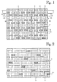
- Figure 1 is a view of a paper machine fabric of the invention as seen from the paper side
- Figure 2 is a view of the paper machine fabric according to Figure 1 as seen from the machine side,
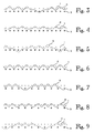
- Figure 3 is a view as seen according to arrows III - III of Figure 1,
- Figure 4 is a view as seen according to arrows IV - IV of Figure 1,
- Figure 5 is a view as seen according to arrows V - V of Figure 1,
- Figure 6 is a view as seen according to arrows VI to VI of Figure 1, and
- Figures 7 to 9 are views of another embodiment of the invention as seen at different yarns, showing the structure in a similar manner to that in Figures 3 to 6.
- the figures show an embodiment of the paper machine fabric of the invention.
- the paper machine fabric of the invention is provided with at least two machine direction yarn systems, e.g. a top warp system and a bottom warp system and at least two cross machine yarn systems, e.g. a top weft system and a bottom weft system.
- the fabric structure further comprises a binder yarn system.
- top warp system and the top weft system form a layer forming the paper side, and, similarly, the bottom warp system and the bottom weft system form a layer forming the machine side.
- top warps are designated by reference number 1 and top wefts by reference number 2.
- Bottom warps are designated by reference number 3 and bottom wefts by reference number 4 in the figures.
- the layer forming the paper side and the layer forming the machine side are bound together using a binder yarn system.
- binder yarns are designated by reference number 5.
- a binder yarn 5 forms part of the weave of the layer, and enters and exits the machine side to bind the layers together by becoming interwoven under at least one bottom warp 3.
- the yarn system forming the paper side comprises a substitute yarn 6, in the example of the figures a substitute weft 6, a binder yarn 5 being woven on both sides thereof.
- the substitute yarn 6 is arranged to replenish the two yarn paths formed by the above-mentioned two binder yarns 5, in the example of the figures a weft path, at points where the above-mentioned two binder yarns are interwoven with the machine side.
- the above-mentioned substitute weft 6 thus replenishes the weft paths formed by the binder yarn woven on both sides of the substitute weft at the points where the binder yarn 5 is interwoven with the machine side.
- the binder yarns 5 and the substitute weft 6 woven therebetween thus form two weft paths on the paper side surface that are similar to the weft path of an actual top weft 2. Consequently, the two binder yarns 5 and the substitute weft 6 woven therebetween form two weft paths on the paper side surface.
- the travel paths in the fabric of the binder yarns 5 adjacent to the substitute weft 6 may be similar or different.
- the number of binding points of the substitute yarn 6 on the paper side surface of the fabric may be the same as or it may differ from the number of binding points of the adjacent binder yarn 5 on the paper side surface.
- the top weft system comprises top wefts of at least one kind. If there is only one top weft, it is a substitute weft 6.
- the example of the figures shows an embodiment wherein the top weft system comprises both ordinary top wefts 2 and substitute wefts 6.
- the binding of the top weft 2 may be similar to or different from that of the weft paths formed jointly by the binder yarns 5 and the substitute yarn 6 on the paper side surface.
- the top weft 2, binder yarn 5, substitute weft 6 and the binder yarn 5 constitute a group of yarns that regularly and repeatedly runs through the fabric.
- the top weft 2 is bound using a plain weave.
- the binder yarn 5 is bound on the paper side surface using a plain weave, descending to bind the layers together by being interwoven under one bottom warp 3, as shown e.g. in Figures 3 and 5.
- the substitute weft 6 replenishes the weft path formed by the binder yarn 5 while the binder yarn 5 is interwoven with the machine side.
- the two binder yarns 5 and the substitute weft 6 form two plain weave weft paths on the paper side surface.
- the weave of the bottom wefts is a 5-shed satin.
- the weave of the binder yarns in this example is a 10-shed one.
- the substitute weft 6 Since the substitute weft 6 is only interwoven with the paper side layer, it does not form, jointly with the binder yarn 5, a similar intersection to that formed by the binder yarn pairs in the structures bound using a binder yarn pair. Consequently, the substitute weft 6 easily sets in appropriate places in order to replenish the weft paths formed by the binder yarns 5 positioned on its both sides and the substitute weft 6 itself. Thanks to the structure, the weft paths formed by the binder yarns 5 and the substitute weft 6 are straight. When all weft paths are straight, openings that appear in the paper side surface can be made as equal in size as possible. This guarantees good and uniform support for the paper fibres on the paper side surface of the entire fabric.
- a further advantage of the structure is that the capillaries of the water drainage system are uniform in size and shape, which enables controlled and even water drainage to be achieved. Thanks to these structural properties, the paper is provided with a good forming and even surfaces.
- PROPERTY Structure of the invention Conventional triple layer fabric Structure bound using a binder yarn pair MD YARNS: ⁇ / density Top warp (mm/yarns/cm) 0.15/34 0.15/34 0.15/34 Bottom warp (mm/yarns/cm) 0.19/34 0.19/34 0.19/34 CMD YARNS: ⁇ / density Top weft (mm/yarns/cm) 0.13/12.6 0.15/26.5 0.13/19.3 Substitute weft (mm/yarns/cm) 0.13/12.6 - - Binder weft (mm/yarns/cm) 0.13/12.6 0.13/7 0.13/19.3 Bottom weft (mm/yarns/cm) 0.22/25.2 0.
- the accompanying table shows the solution of the invention, a conventional triple layer fabric structure and a structure bound using a binder yarn pair being compared.
- the structure of the invention combines the good properties of the conventional triple layer fabric structure and the structure bound using a binder yarn pair.
- the structure of the invention enables as high wear resistance as the conventional triple layer fabric structure and clearly higher wear resistance than the structure bound using a binder yarn pair to be achieved. This is indicated by the bottom weft density.
- Fibre Support Index (FSI) describes the level of support provided by the fabric for the paper fibres. S-index indicates the number of paper side yarns per square centimetre.
- the fibre support achieved by the structure of the invention is as good as the fibre support achieved by the structure bound using a binder yarn pair, and it is clearly better than that achieved by the conventional triple layer fabric structure.
- the binder yarns 5 and the top wefts 2 are interwoven with each top warp 1, unlike in the most common structures bound using a binder yarn pair where the binder yarns are interwoven with every other top warp and the top wefts are interwoven with every other top warp.
- all top warps 1 are positioned on the same plane with respect to the surface, and no marking in the warp direction occurs.
- the structure of the invention also provides higher wear resistance than the most common structures bound using a binder yarn pair and provided with the same permeability. For example, if ten weft paths are to be provided on the paper side surface, the structure of the invention requires thirteen yarns while the structure bound using binder yarn pairs requires fifteen yarns. In the structure of the invention, this advantage enables more weft yarns to be woven on the bottom side than in the structures bound using a binder yarn pair and provided with similar permeability, i.e. the bottom side can be provided with more yarn material to be worn down, which means higher wear resistance.
- Figures 7 to 9 schematically show another embodiment of the solution of the invention.
- the structure is for the most part shown in the same manner as the previous embodiment in Figures 3 to 6.
- the same numbers have the same significance to indicate corresponding features as in Figures 1 to 6.
- the zigzag of the binder yarns 5 differs from the application of Figures 1 to 6 and, furthermore, in the embodiment of Figures 7 to 9, one bottom warp 3 corresponds to two top warps 1.
- the travel paths of the binder yarns adjacent to the substitute weft 6 are different.
- the embodiments disclosed above are by no means intended to restrict the invention, but the invention can be modified freely within the scope of the claims. It is thus obvious that the paper machine fabric of the invention or the details thereof do not necessarily have to be identical to those shown in the figures but other solutions are also feasible.
- the separate layers can be formed very freely, i.e. such that the number of yarn systems may vary, the essential point being that there are at least two warp systems: a bottom warp system and a top warp system. Similarly, the number of weft systems may also vary, the essential point being that there are at least two weft systems: a top weft system and a bottom weft system etc.
- the structure of the invention described above is a triple layer one, but other multilayer structures are feasible within the scope of the invention.
- the basic idea of the invention enables structures that completely lack top wefts, i.e. a structure wherein the paper side is provided with substitute wefts only.
- the number of top wefts is larger than the number of substitute wefts, i.e. the number of top wefts may vary, being e.g. 0, 1, 2, 3, etc.
- the number of bottom wefts may differ from the total number of top wefts and substitute wefts.
- the ratio of top warps to bottom warps is usually 1:1, but it may also be a different one.
- the diameters of the yarns may be e.g. as follows: top warp 0.12 - 0.15, bottom warp 0.17 - 0.21, substitute weft 0.10 - 0.16, top weft 0.10 - 0.16, binder yarn 0.10 - 0.16, and bottom weft 0.17 - 0.30. The above values are given in millimetres.
- the diameters of the yarns may, however, be other than what has been disclosed above.
- the solution set forth above employs polyester or polyamide yarns with circular cross-sections.
- PEN polyethylene naphthalate
- PPS polyphenylene sulfide
- the cross-section of the yarns may also be flat or oval.
- the properties of the yarns affect the properties of the fabric. For example, by choosing a substitute weft with a low bending stiffness, the paper side binding points of the substitute weft easily set in appropriate places in the path formed by the binder yarn and the substitute weft, which means that the path is as straight as possible.
- the bending stiffnesses of the substitute weft and the top wefts may be equal or unequal.
- the binding takes place in the weft direction.
- the structure comprises at least a binder warp, substitute warp, bottom warp, top weft and bottom weft.
- the substitute yarn can thus be either a substitute weft or a substitute warp.
Landscapes
- Paper (AREA)
- Woven Fabrics (AREA)
- Diaphragms For Electromechanical Transducers (AREA)
- Polarising Elements (AREA)
- Non-Silver Salt Photosensitive Materials And Non-Silver Salt Photography (AREA)
- Chemical Or Physical Treatment Of Fibers (AREA)
- Crystals, And After-Treatments Of Crystals (AREA)
- Photographic Developing Apparatuses (AREA)
Claims (18)
- Papiermaschinengewebe mit mindestens zwei getrennten Schichten, die mit mindestens zwei getrennten Fadensystemen ausgebildet sind: einem Fadensystem, das die Papierseite bildet und Maschinenrichtungs- und Quermaschinenrichtungsfäden umfasst, und einem Fadensystem, das die Maschinenseite bildet und Maschinenrichtungs- und Quermaschinenrichtungsfäden umfasst, wobei die Fadensysteme angeordnet sind, um unabhängige Strukturen in den Maschinen- und Quermaschinenrichtungen des Gewebes zu bilden, und die Strukturen mittels Binderfäden (5) zusammen gebunden sind, wobei ein Binderfaden (5) angeordnet ist, um einen Teil der Bindung einer Schicht auf der Papierseitenoberfläche zu bilden, und angeordnet ist, um mit einer Schicht der Maschinenseite verflochten zu sein, indem er unter mindestens einem Faden in der Maschinenseite verflochten ist, dadurch gekennzeichnet, dass das die Papierseite bildende Fadensystem ferner einen Ersatzfaden (6) umfasst, der mit einem an beiden Seiten davon verwobenen Binderfaden (5) versehen ist, und der Ersatzfaden (6) an der Papierseite angeordnet ist, um die durch die oben erwähnten beiden Binderfäden (5) gebildeten beiden Fadenläufe an Punkten wieder zu ergänzen, an denen die oben erwähnten beiden Binderfäden (5) mit der Maschinenseite verflochten sind.
- Papiermaschinengewebe gemäß Anspruch 1, dadurch gekennzeichnet, dass der Ersatzfaden (6) ein Ersatzschuss und der Binderfaden (5) ein Binderschuss ist.
- Papiermaschinengewebe gemäß Anspruch 1, dadurch gekennzeichnet, dass der Ersatzfaden (6) eine Ersatzkette und der Binderfaden (5) eine Binderkette ist.
- Papiermaschinengewebe gemäß Anspruch 2, dadurch gekennzeichnet, dass zusätzlich zu dem Ersatzschuss (6) die Papierseitenoberfläche mit mindestens einem oberen Schuss (2) versehen ist.
- Papiennaschinengewebe gemäß Anspruch 2, dadurch gekennzeichnet, dass zusätzlich zu dem Ersatzschuss (6) die Papierseitenoberfläche mit einem oberen Schuss (2) versehen ist.
- Papiermaschinengewebe gemäß Anspruch 4, dadurch gekennzeichnet, dass die Biegesteifigkeit des Ersatzschusses (6) und des oberen Schusses gleich sind.
- Papiermaschinengewebe gemäß Anspruch 4, dadurch gekennzeichnet, dass die Biegesteifigkeit des Ersatzschusses (6) und des oberen Schusses (2) ungleich sind.
- Papiermaschinengewebe gemäß Anspruch 1, dadurch gekennzeichnet, dass die Laufbahnen in dem Gewebe der Binderfäden (5) benachbart dem Ersatzfaden (6) ähnlich sind.
- Papiermaschinengewebe gemäß Anspruch 1, dadurch gekennzeichnet, dass die Laufbahnen in dem Gewebe der Binderfäden (5) benachbart dem Ersatzfaden (6) unterschiedlich sind.
- Papiermaschinengewebe gemäß Anspruch 8, dadurch gekennzeichnet, dass der Binderfaden (5) drei Bindepunkte auf der Papierseitenoberfläche umfasst.
- Papiermaschinengewebe gemäß Anspruch 4, dadurch gekennzeichnet, dass die Bindung des oberen Schusses (2) ähnlich der der Schussbahnen ist, die gemeinsam durch die Binderfäden (5) und dem Ersatzschuss (6) auf der Papierseitenoberfläche ausgebildet werden.
- Papiermaschinengewebe gemäß Anspruch 4, dadurch gekennzeichnet, dass die Bindung des oberen Schusses (2) von der der Schussläufe unterschiedlich ist, die gemeinsam durch die Binderfäden (5) und dem Ersatzschuss (6) auf der Papierseitenoberfläche ausgebildet werden.
- Papiermaschinengewebe gemäß Anspruch 1, dadurch gekennzeichnet, dass die Papierseitenoberfläche mit Leinenbindungs-Fadenläufen versehen ist.
- Papiermaschinengewebe gemäß Anspruch 1, dadurch gekennzeichnet, dass die Anzahl von Bindepunkten des Ersatzfadens (6) auf der Papierseitenoberfläche ähnlich zu oder unterschiedlich von der Anzahl von Bindepunkten eines benachbarten Binderfadens (5) auf der Papierseitenoberfläche ist.
- Papiermaschinengewebe gemäß Anspruch 4, dadurch gekennzeichnet, dass die Anzahl von Ersatzschüssen (6) gleich der Anzahl von oberen Schüssen (2) und die Anzahl von unteren Schüssen (4) gleich der Gesamtanzahl von oberen Schüssen (2) und Ersatzschüssen (6) ist.
- Papiermaschinengewebe gemäß Anspruch 15, dadurch gekennzeichnet, dass der durch den Ersatzschuss (6) gebildete Schusslauf und die Binderfäden (5) angeordnet sind, um drei Bindepunkte für die Binderfäden (5) und zwei Bindepunkte für den Ersatzschuss (6) zu umfassen.
- Papiermaschinengewebe gemäß Anspruch 16, dadurch gekennzeichnet, dass die Binderfäden (5) unter einem unteren Schuss mit einer 10-Fach-Bindung und die unteren Schüsse (4) mit den unteren Ketten (3) mit einer 5-Fach-Atlasbindung verflochten sind.
- Papiermaschinengewebe gemäß Anspruch 3, dadurch gekennzeichnet, dass zusätzlich zu dem Ersatzschuss die Papierseitenoberfläche mit mindestens einem oberen Schuss (1) versehen ist.
Applications Claiming Priority (3)
| Application Number | Priority Date | Filing Date | Title |
|---|---|---|---|
| FI20010348 | 2001-02-22 | ||
| FI20010348A FI110131B (fi) | 2001-02-22 | 2001-02-22 | Paperikonekudos |
| PCT/FI2002/000143 WO2002066733A1 (en) | 2001-02-22 | 2002-02-21 | Paper machine fabric |
Publications (2)
| Publication Number | Publication Date |
|---|---|
| EP1362142A1 EP1362142A1 (de) | 2003-11-19 |
| EP1362142B1 true EP1362142B1 (de) | 2006-06-07 |
Family
ID=8560472
Family Applications (1)
| Application Number | Title | Priority Date | Filing Date |
|---|---|---|---|
| EP02700312A Expired - Lifetime EP1362142B1 (de) | 2001-02-22 | 2002-02-21 | Papiermaschinen gewebe |
Country Status (15)
| Country | Link |
|---|---|
| US (1) | US6354335B1 (de) |
| EP (1) | EP1362142B1 (de) |
| JP (1) | JP3839778B2 (de) |
| KR (1) | KR100515663B1 (de) |
| CN (1) | CN1179090C (de) |
| AT (1) | ATE329080T1 (de) |
| AU (1) | AU2002233400B2 (de) |
| CA (1) | CA2404182C (de) |
| DE (1) | DE60212077T2 (de) |
| DK (1) | DK1362142T3 (de) |
| ES (1) | ES2260411T3 (de) |
| FI (1) | FI110131B (de) |
| NO (1) | NO20025080D0 (de) |
| PT (1) | PT1362142E (de) |
| WO (1) | WO2002066733A1 (de) |
Cited By (2)
| Publication number | Priority date | Publication date | Assignee | Title |
|---|---|---|---|---|
| EP2199458A1 (de) | 2008-12-22 | 2010-06-23 | Helmbach GmbH & Co.KG | Formiersieb |
| CN101440583B (zh) * | 2008-12-29 | 2012-07-25 | 安徽华辰造纸网股份有限公司 | 一种接结双层组织的造纸用成形网 |
Families Citing this family (42)
| Publication number | Priority date | Publication date | Assignee | Title |
|---|---|---|---|---|
| GB0005344D0 (en) * | 2000-03-06 | 2000-04-26 | Stone Richard | Forming fabric with machine side layer weft binder yarns |
| DE10039736A1 (de) * | 2000-08-16 | 2002-03-07 | Kufferath Andreas Gmbh | Verbundgewebe |
| JP3933448B2 (ja) * | 2001-11-22 | 2007-06-20 | 日本フイルコン株式会社 | 工業用多層織物 |
| FI112261B (fi) * | 2002-05-06 | 2003-11-14 | Tamfelt Oyj Abp | Paperikonekudos |
| US20050288387A1 (en) * | 2002-08-21 | 2005-12-29 | Li Feng | Acrylate dental compositions with improved viscosity and storage odor |
| US6837275B2 (en) * | 2002-11-07 | 2005-01-04 | Albany International Corp. | Air channel dryer fabric |
| US6769535B2 (en) * | 2002-11-07 | 2004-08-03 | Albany International Corp. | High drainage dimensionallally stable brownstock washer belt design |
| US6837276B2 (en) * | 2002-11-07 | 2005-01-04 | Albany International Corp. | Air channel dryer fabric |
| US6860969B2 (en) * | 2003-01-30 | 2005-03-01 | Weavexx Corporation | Papermaker's forming fabric |
| US7059357B2 (en) * | 2003-03-19 | 2006-06-13 | Weavexx Corporation | Warp-stitched multilayer papermaker's fabrics |
| US6905574B2 (en) * | 2003-04-18 | 2005-06-14 | Albany International Corp. | Multi-layer forming fabric with two warp systems bound together with a triplet of binder yarns |
| US7303656B2 (en) * | 2003-07-02 | 2007-12-04 | Albany International Corp. | Low permeability textile substrate for a two-sided coated product |
| GB0316417D0 (en) * | 2003-07-12 | 2003-08-20 | Voith Fabrics Gmbh & Co Kg | Forming fabrics |
| EP1656480A1 (de) * | 2003-08-13 | 2006-05-17 | Voith Fabrics Patent GmbH | Bespannungen mit sich jeweils kreuzenden fadenpaaren aus bindefaden einerseits und einem oberseitig einbindenden faden andererseits |
| WO2005047581A1 (en) * | 2003-11-06 | 2005-05-26 | Hexcel Corporation | Interlock double weave fabric and methods of making and using the same |
| DE102004035522A1 (de) * | 2004-07-22 | 2006-03-16 | Voith Fabrics Patent Gmbh | Papiermaschinenbespannung |
| DE102004035519A1 (de) * | 2004-07-22 | 2006-02-09 | Voith Fabrics Patent Gmbh | Papiermaschinenbespannung |
| DE102004035523A1 (de) * | 2004-07-22 | 2006-02-09 | Voith Fabrics Patent Gmbh | Papiermaschinenbespannung |
| US7124781B2 (en) * | 2005-02-01 | 2006-10-24 | Albany International Corp. | Multiple contour binders in triple layer fabrics |
| KR100670913B1 (ko) * | 2005-04-01 | 2007-01-17 | 주움텍스타일 주식회사 | 연마기재, 연마기재의 제조방법 및 연마포 |
| JP4563260B2 (ja) * | 2005-06-14 | 2010-10-13 | 日本フイルコン株式会社 | 工業用二層織物 |
| US7503350B2 (en) * | 2005-08-03 | 2009-03-17 | Voith Patent Gmbh | Compound forming fabric with additional bottom yarns |
| KR100830573B1 (ko) * | 2005-09-27 | 2008-05-21 | 웨벡스 코포레이션 | 기계측 너클을 형성하는 기계방향 접결사를 가진 제지기용성형 직물 |
| FI118856B (fi) * | 2005-10-06 | 2008-04-15 | Tamfelt Pmc Oy | Paperikonekudos |
| JP4739903B2 (ja) | 2005-10-17 | 2011-08-03 | 日本フイルコン株式会社 | 工業用二層織物 |
| US7357155B2 (en) * | 2005-12-29 | 2008-04-15 | Albany International Corp. | Different contour paired binders in multi-layer fabrics |
| DE102006016660C5 (de) * | 2006-04-08 | 2009-09-03 | Andreas Kufferath Gmbh & Co Kg | Oberseite, insbesondere Papierseite, sowie Papiermaschinensieb |
| KR100675407B1 (ko) * | 2006-09-26 | 2007-01-30 | 주움텍스타일 주식회사 | 연마기재 및 연마포 |
| WO2008068317A1 (de) * | 2006-12-08 | 2008-06-12 | Voith Patent Gmbh | Gewebeband für eine maschine zur herstellung von bahnmaterial, insbesondere papier oder karton |
| WO2008073301A2 (en) * | 2006-12-08 | 2008-06-19 | Astenjohnson, Inc. | Machine side layer weave design for composite forming fabrics |
| DE102006059482A1 (de) * | 2006-12-08 | 2008-06-12 | Voith Patent Gmbh | Gewebeband für eine Maschine zur Herstellung von Bahnmaterial, insbesondere Papier oder Karton |
| ATE507346T1 (de) * | 2007-12-04 | 2011-05-15 | Heimbach Gmbh & Co Kg | Formiersieb für den einsatz in einer papiermaschine |
| CA2634432A1 (en) * | 2008-06-09 | 2009-12-09 | Richard Stone | High fiber support intrinsic warp tied composite forming fabric |
| IT1391374B1 (it) * | 2008-10-08 | 2011-12-13 | Feltri Marone S P A | Tessuto triplo di fabbricazione della carta |
| JP5281877B2 (ja) * | 2008-11-28 | 2013-09-04 | 日本フイルコン株式会社 | 工業用二層織物 |
| FI20115222L (fi) | 2011-03-04 | 2012-09-05 | Metso Fabrics Oy | Paperikonekudos |
| DE102013106327B4 (de) | 2013-06-18 | 2015-01-08 | Andritz Technology And Asset Management Gmbh | Papiermaschinensieb |
| DE102013108399B3 (de) * | 2013-08-05 | 2014-11-27 | ANDRITZ KUFFERATH GmbH | Papiermaschinensieb, dessen laufseite querfäden mit unterschiedlicher flottierungslänge aufweist |
| CN106192525B (zh) * | 2016-08-03 | 2020-12-22 | 江苏金呢工程织物股份有限公司 | 一种三层造纸网织造方法以及三层造纸网 |
| FI128025B (en) * | 2017-03-24 | 2019-08-15 | Valmet Technologies Oy | industrial Textiles |
| US11339534B2 (en) | 2019-09-18 | 2022-05-24 | Huyck Licensco Inc. | Multi-layer warp bound papermaker's forming fabrics |
| FI20206371A1 (en) * | 2020-12-23 | 2022-06-24 | Valmet Technologies Inc | Industrial textile |
Family Cites Families (12)
| Publication number | Priority date | Publication date | Assignee | Title |
|---|---|---|---|---|
| SE430425C (sv) * | 1981-06-23 | 1986-09-19 | Nordiskafilt Ab | Formeringsvira for pappers-, cellulosa- eller liknande maskiner |
| ATE43376T1 (de) | 1984-06-14 | 1989-06-15 | Oberdorfer Fa F | Papiermaschinen-sieb. |
| JPS6257996A (ja) * | 1985-09-04 | 1987-03-13 | 日本フイルコン株式会社 | 製紙用2重織物 |
| JPS62162091A (ja) * | 1986-01-09 | 1987-07-17 | 日本フイルコン株式会社 | 製紙用2重織物 |
| DE3923938A1 (de) * | 1989-07-19 | 1991-01-31 | Oberdorfer Fa F | Formiergewebe fuer die nasspartie einer papiermaschine |
| US4987929A (en) * | 1989-08-25 | 1991-01-29 | Huyck Corporation | Forming fabric with interposing cross machine direction yarns |
| US5482567A (en) * | 1994-12-06 | 1996-01-09 | Huyck Licensco, Inc. | Multilayer forming fabric |
| JP3728339B2 (ja) * | 1995-09-29 | 2005-12-21 | 日本フイルコン株式会社 | 経糸二重緯糸二重構造の製紙用織物 |
| GB9604602D0 (en) | 1996-03-04 | 1996-05-01 | Jwi Ltd | Composite papermaking fabric with paired weft binder yarns |
| US5967195A (en) | 1997-08-01 | 1999-10-19 | Weavexx Corporation | Multi-layer forming fabric with stitching yarn pairs integrated into papermaking surface |
| GB9811089D0 (en) * | 1998-05-23 | 1998-07-22 | Jwi Ltd | Warp-tied composite forming fabric |
| GB9924012D0 (en) * | 1999-10-12 | 1999-12-15 | Stone Richard | Forming fabric woven with warp triplets |
-
2001
- 2001-02-22 FI FI20010348A patent/FI110131B/fi not_active IP Right Cessation
- 2001-05-11 US US09/852,734 patent/US6354335B1/en not_active Expired - Lifetime
-
2002
- 2002-02-21 KR KR10-2002-7013554A patent/KR100515663B1/ko not_active IP Right Cessation
- 2002-02-21 EP EP02700312A patent/EP1362142B1/de not_active Expired - Lifetime
- 2002-02-21 AU AU2002233400A patent/AU2002233400B2/en not_active Ceased
- 2002-02-21 CA CA002404182A patent/CA2404182C/en not_active Expired - Fee Related
- 2002-02-21 AT AT02700312T patent/ATE329080T1/de active
- 2002-02-21 JP JP2002566029A patent/JP3839778B2/ja not_active Expired - Fee Related
- 2002-02-21 ES ES02700312T patent/ES2260411T3/es not_active Expired - Lifetime
- 2002-02-21 CN CNB028003799A patent/CN1179090C/zh not_active Expired - Fee Related
- 2002-02-21 WO PCT/FI2002/000143 patent/WO2002066733A1/en active IP Right Grant
- 2002-02-21 DE DE60212077T patent/DE60212077T2/de not_active Expired - Lifetime
- 2002-02-21 PT PT02700312T patent/PT1362142E/pt unknown
- 2002-02-21 DK DK02700312T patent/DK1362142T3/da active
- 2002-10-22 NO NO20025080A patent/NO20025080D0/no not_active Application Discontinuation
Cited By (2)
| Publication number | Priority date | Publication date | Assignee | Title |
|---|---|---|---|---|
| EP2199458A1 (de) | 2008-12-22 | 2010-06-23 | Helmbach GmbH & Co.KG | Formiersieb |
| CN101440583B (zh) * | 2008-12-29 | 2012-07-25 | 安徽华辰造纸网股份有限公司 | 一种接结双层组织的造纸用成形网 |
Also Published As
| Publication number | Publication date |
|---|---|
| CN1179090C (zh) | 2004-12-08 |
| EP1362142A1 (de) | 2003-11-19 |
| CA2404182C (en) | 2007-01-09 |
| PT1362142E (pt) | 2006-08-31 |
| DE60212077D1 (de) | 2006-07-20 |
| ATE329080T1 (de) | 2006-06-15 |
| KR100515663B1 (ko) | 2005-09-23 |
| AU2002233400B2 (en) | 2006-06-01 |
| JP3839778B2 (ja) | 2006-11-01 |
| ES2260411T3 (es) | 2006-11-01 |
| US6354335B1 (en) | 2002-03-12 |
| CA2404182A1 (en) | 2002-08-29 |
| WO2002066733A1 (en) | 2002-08-29 |
| CN1457379A (zh) | 2003-11-19 |
| NO20025080L (no) | 2002-10-22 |
| FI110131B (fi) | 2002-11-29 |
| JP2004518833A (ja) | 2004-06-24 |
| FI20010348A0 (fi) | 2001-02-22 |
| KR20020089445A (ko) | 2002-11-29 |
| FI20010348A (fi) | 2002-08-23 |
| WO2002066733A8 (en) | 2003-12-04 |
| DK1362142T3 (da) | 2006-09-04 |
| NO20025080D0 (no) | 2002-10-22 |
| DE60212077T2 (de) | 2006-11-09 |
Similar Documents
| Publication | Publication Date | Title |
|---|---|---|
| EP1362142B1 (de) | Papiermaschinen gewebe | |
| EP1506339B1 (de) | Papiermaschinenbespannung | |
| US4729412A (en) | Forming fabric of double-layer type | |
| EP1662039B1 (de) | Zweilagiges technisches Gewebe | |
| CA2606639C (en) | Bulk enhancing forming fabrics | |
| EP1662040B1 (de) | Zweilagiges technisches Gewebe | |
| EP0431750B1 (de) | Mehrlagiges Papiermachergewebe für einen Durchblasetrockner | |
| CA2516903C (en) | Industrial two-layer fabric | |
| EP0414148A2 (de) | Formiergewebe mit zwischenliegenden Querfäden | |
| EP1717365B1 (de) | Stabiles Formiersieb mit hoher Faserunterstützung | |
| US6276402B1 (en) | Multilayer papermakers fabric | |
| CA2759358A1 (en) | Industrial two-layer fabric | |
| CN101278091B (zh) | 造纸机织物 | |
| CA2759355C (en) | Industrial two-layer fabric | |
| EP0106132A2 (de) | Papiermachergewebe mit gestrickten Garnen | |
| EP2337893B1 (de) | Papiermaschinenbespannung, insbesondere für die nasspartie einer papiermaschine | |
| KR100528373B1 (ko) | 성형 직물 |
Legal Events
| Date | Code | Title | Description |
|---|---|---|---|
| PUAI | Public reference made under article 153(3) epc to a published international application that has entered the european phase |
Free format text: ORIGINAL CODE: 0009012 |
|
| 17P | Request for examination filed |
Effective date: 20021115 |
|
| AK | Designated contracting states |
Kind code of ref document: A1 Designated state(s): AT BE CH CY DE DK ES FI FR GB GR IE IT LI LU MC NL PT SE TR |
|
| AX | Request for extension of the european patent |
Extension state: AL LT LV MK RO SI |
|
| GRAP | Despatch of communication of intention to grant a patent |
Free format text: ORIGINAL CODE: EPIDOSNIGR1 |
|
| GRAS | Grant fee paid |
Free format text: ORIGINAL CODE: EPIDOSNIGR3 |
|
| GRAA | (expected) grant |
Free format text: ORIGINAL CODE: 0009210 |
|
| RIN1 | Information on inventor provided before grant (corrected) |
Inventor name: RAUTIO, TANIA Inventor name: KORTELAINEN, PEKKA Inventor name: TAIPALE, SEPPO Inventor name: TURPEINEN, TERTTU |
|
| AK | Designated contracting states |
Kind code of ref document: B1 Designated state(s): AT BE CH CY DE DK ES FI FR GB GR IE IT LI LU MC NL PT SE TR |
|
| PG25 | Lapsed in a contracting state [announced via postgrant information from national office to epo] |
Ref country code: IT Free format text: LAPSE BECAUSE OF FAILURE TO SUBMIT A TRANSLATION OF THE DESCRIPTION OR TO PAY THE FEE WITHIN THE PRESCRIBED TIME-LIMIT;WARNING: LAPSES OF ITALIAN PATENTS WITH EFFECTIVE DATE BEFORE 2007 MAY HAVE OCCURRED AT ANY TIME BEFORE 2007. THE CORRECT EFFECTIVE DATE MAY BE DIFFERENT FROM THE ONE RECORDED. Effective date: 20060607 Ref country code: FI Free format text: LAPSE BECAUSE OF FAILURE TO SUBMIT A TRANSLATION OF THE DESCRIPTION OR TO PAY THE FEE WITHIN THE PRESCRIBED TIME-LIMIT Effective date: 20060607 |
|
| REG | Reference to a national code |
Ref country code: GB Ref legal event code: FG4D |
|
| REG | Reference to a national code |
Ref country code: CH Ref legal event code: EP |
|
| REG | Reference to a national code |
Ref country code: IE Ref legal event code: FG4D |
|
| REF | Corresponds to: |
Ref document number: 60212077 Country of ref document: DE Date of ref document: 20060720 Kind code of ref document: P |
|
| REG | Reference to a national code |
Ref country code: PT Ref legal event code: SC4A Effective date: 20060629 |
|
| REG | Reference to a national code |
Ref country code: DK Ref legal event code: T3 |
|
| REG | Reference to a national code |
Ref country code: SE Ref legal event code: TRGR |
|
| REG | Reference to a national code |
Ref country code: ES Ref legal event code: FG2A Ref document number: 2260411 Country of ref document: ES Kind code of ref document: T3 |
|
| ET | Fr: translation filed | ||
| PG25 | Lapsed in a contracting state [announced via postgrant information from national office to epo] |
Ref country code: MC Free format text: LAPSE BECAUSE OF NON-PAYMENT OF DUE FEES Effective date: 20070228 |
|
| PLBE | No opposition filed within time limit |
Free format text: ORIGINAL CODE: 0009261 |
|
| STAA | Information on the status of an ep patent application or granted ep patent |
Free format text: STATUS: NO OPPOSITION FILED WITHIN TIME LIMIT |
|
| 26N | No opposition filed |
Effective date: 20070308 |
|
| REG | Reference to a national code |
Ref country code: CH Ref legal event code: PFA Owner name: TAMFELT OYJ ABP Free format text: TAMFELT OYJ ABP#YRITTAEJAENKATU 21#33710 TAMPERE (FI) -TRANSFER TO- TAMFELT OYJ ABP#YRITTAEJAENKATU 21#33710 TAMPERE (FI) |
|
| PG25 | Lapsed in a contracting state [announced via postgrant information from national office to epo] |
Ref country code: IE Free format text: LAPSE BECAUSE OF NON-PAYMENT OF DUE FEES Effective date: 20070221 |
|
| PG25 | Lapsed in a contracting state [announced via postgrant information from national office to epo] |
Ref country code: GR Free format text: LAPSE BECAUSE OF FAILURE TO SUBMIT A TRANSLATION OF THE DESCRIPTION OR TO PAY THE FEE WITHIN THE PRESCRIBED TIME-LIMIT Effective date: 20060908 |
|
| PGFP | Annual fee paid to national office [announced via postgrant information from national office to epo] |
Ref country code: DK Payment date: 20080226 Year of fee payment: 7 |
|
| REG | Reference to a national code |
Ref country code: CH Ref legal event code: PUE Owner name: TAMFELT PMC OY Free format text: TAMFELT OYJ ABP#YRITTAEJAENKATU 21#33710 TAMPERE (FI) -TRANSFER TO- TAMFELT PMC OY#YRITTAEJAENKATU 21#33700 TAMPERE (FI) |
|
| PGFP | Annual fee paid to national office [announced via postgrant information from national office to epo] |
Ref country code: NL Payment date: 20080221 Year of fee payment: 7 |
|
| REG | Reference to a national code |
Ref country code: GB Ref legal event code: 732E |
|
| REG | Reference to a national code |
Ref country code: PT Ref legal event code: PC4A Owner name: TAMFELT PMC OY, FI Effective date: 20080530 |
|
| NLS | Nl: assignments of ep-patents |
Owner name: TAMFELT PMC OY Effective date: 20080425 |
|
| REG | Reference to a national code |
Ref country code: FR Ref legal event code: TP |
|
| PG25 | Lapsed in a contracting state [announced via postgrant information from national office to epo] |
Ref country code: LU Free format text: LAPSE BECAUSE OF NON-PAYMENT OF DUE FEES Effective date: 20070221 Ref country code: CY Free format text: LAPSE BECAUSE OF FAILURE TO SUBMIT A TRANSLATION OF THE DESCRIPTION OR TO PAY THE FEE WITHIN THE PRESCRIBED TIME-LIMIT Effective date: 20060607 |
|
| PG25 | Lapsed in a contracting state [announced via postgrant information from national office to epo] |
Ref country code: TR Free format text: LAPSE BECAUSE OF FAILURE TO SUBMIT A TRANSLATION OF THE DESCRIPTION OR TO PAY THE FEE WITHIN THE PRESCRIBED TIME-LIMIT Effective date: 20060607 |
|
| REG | Reference to a national code |
Ref country code: DK Ref legal event code: EBP |
|
| NLV4 | Nl: lapsed or anulled due to non-payment of the annual fee |
Effective date: 20090901 |
|
| PG25 | Lapsed in a contracting state [announced via postgrant information from national office to epo] |
Ref country code: NL Free format text: LAPSE BECAUSE OF NON-PAYMENT OF DUE FEES Effective date: 20090901 |
|
| PG25 | Lapsed in a contracting state [announced via postgrant information from national office to epo] |
Ref country code: DK Free format text: LAPSE BECAUSE OF NON-PAYMENT OF DUE FEES Effective date: 20090831 |
|
| REG | Reference to a national code |
Ref country code: DE Ref legal event code: R082 Ref document number: 60212077 Country of ref document: DE Representative=s name: MAI DOERR BESIER PATENTANWAELTE, DE Ref country code: DE Ref legal event code: R082 Ref document number: 60212077 Country of ref document: DE Representative=s name: MAI DOERR BESIER EUROPEAN PATENT ATTORNEYS - E, DE |
|
| REG | Reference to a national code |
Ref country code: FR Ref legal event code: PLFP Year of fee payment: 15 |
|
| PGFP | Annual fee paid to national office [announced via postgrant information from national office to epo] |
Ref country code: CH Payment date: 20160217 Year of fee payment: 15 Ref country code: ES Payment date: 20160210 Year of fee payment: 15 |
|
| PGFP | Annual fee paid to national office [announced via postgrant information from national office to epo] |
Ref country code: SE Payment date: 20160217 Year of fee payment: 15 Ref country code: PT Payment date: 20160219 Year of fee payment: 15 Ref country code: GB Payment date: 20160217 Year of fee payment: 15 Ref country code: BE Payment date: 20160217 Year of fee payment: 15 |
|
| REG | Reference to a national code |
Ref country code: FR Ref legal event code: PLFP Year of fee payment: 16 |
|
| PG25 | Lapsed in a contracting state [announced via postgrant information from national office to epo] |
Ref country code: BE Free format text: LAPSE BECAUSE OF NON-PAYMENT OF DUE FEES Effective date: 20170228 |
|
| REG | Reference to a national code |
Ref country code: CH Ref legal event code: PL |
|
| REG | Reference to a national code |
Ref country code: SE Ref legal event code: EUG |
|
| GBPC | Gb: european patent ceased through non-payment of renewal fee |
Effective date: 20170221 |
|
| PG25 | Lapsed in a contracting state [announced via postgrant information from national office to epo] |
Ref country code: LI Free format text: LAPSE BECAUSE OF NON-PAYMENT OF DUE FEES Effective date: 20170228 Ref country code: CH Free format text: LAPSE BECAUSE OF NON-PAYMENT OF DUE FEES Effective date: 20170228 |
|
| PG25 | Lapsed in a contracting state [announced via postgrant information from national office to epo] |
Ref country code: PT Free format text: LAPSE BECAUSE OF NON-PAYMENT OF DUE FEES Effective date: 20170821 Ref country code: SE Free format text: LAPSE BECAUSE OF NON-PAYMENT OF DUE FEES Effective date: 20170222 |
|
| REG | Reference to a national code |
Ref country code: BE Ref legal event code: MM Effective date: 20170228 |
|
| REG | Reference to a national code |
Ref country code: FR Ref legal event code: PLFP Year of fee payment: 17 |
|
| PG25 | Lapsed in a contracting state [announced via postgrant information from national office to epo] |
Ref country code: GB Free format text: LAPSE BECAUSE OF NON-PAYMENT OF DUE FEES Effective date: 20170221 |
|
| REG | Reference to a national code |
Ref country code: ES Ref legal event code: FD2A Effective date: 20180704 |
|
| PG25 | Lapsed in a contracting state [announced via postgrant information from national office to epo] |
Ref country code: ES Free format text: LAPSE BECAUSE OF NON-PAYMENT OF DUE FEES Effective date: 20170222 |
|
| PGFP | Annual fee paid to national office [announced via postgrant information from national office to epo] |
Ref country code: DE Payment date: 20200219 Year of fee payment: 19 Ref country code: AT Payment date: 20200220 Year of fee payment: 19 Ref country code: IT Payment date: 20200225 Year of fee payment: 19 |
|
| PGFP | Annual fee paid to national office [announced via postgrant information from national office to epo] |
Ref country code: FR Payment date: 20200219 Year of fee payment: 19 |
|
| REG | Reference to a national code |
Ref country code: DE Ref legal event code: R119 Ref document number: 60212077 Country of ref document: DE |
|
| REG | Reference to a national code |
Ref country code: AT Ref legal event code: MM01 Ref document number: 329080 Country of ref document: AT Kind code of ref document: T Effective date: 20210221 |
|
| PG25 | Lapsed in a contracting state [announced via postgrant information from national office to epo] |
Ref country code: AT Free format text: LAPSE BECAUSE OF NON-PAYMENT OF DUE FEES Effective date: 20210221 |
|
| PG25 | Lapsed in a contracting state [announced via postgrant information from national office to epo] |
Ref country code: DE Free format text: LAPSE BECAUSE OF NON-PAYMENT OF DUE FEES Effective date: 20210901 Ref country code: FR Free format text: LAPSE BECAUSE OF NON-PAYMENT OF DUE FEES Effective date: 20210228 |
|
| PG25 | Lapsed in a contracting state [announced via postgrant information from national office to epo] |
Ref country code: IT Free format text: LAPSE BECAUSE OF NON-PAYMENT OF DUE FEES Effective date: 20210221 |