EP1361490A1 - Durchflussmengenregler - Google Patents
Durchflussmengenregler Download PDFInfo
- Publication number
- EP1361490A1 EP1361490A1 EP20030006521 EP03006521A EP1361490A1 EP 1361490 A1 EP1361490 A1 EP 1361490A1 EP 20030006521 EP20030006521 EP 20030006521 EP 03006521 A EP03006521 A EP 03006521A EP 1361490 A1 EP1361490 A1 EP 1361490A1
- Authority
- EP
- European Patent Office
- Prior art keywords
- fixing
- webs
- tower
- throttle body
- flow rate
- Prior art date
- Legal status (The legal status is an assumption and is not a legal conclusion. Google has not performed a legal analysis and makes no representation as to the accuracy of the status listed.)
- Granted
Links
- 230000015572 biosynthetic process Effects 0.000 claims description 8
- 238000005755 formation reaction Methods 0.000 claims description 8
- 239000013013 elastic material Substances 0.000 claims description 4
- 230000002093 peripheral effect Effects 0.000 claims description 4
- 238000002347 injection Methods 0.000 description 8
- 239000007924 injection Substances 0.000 description 8
- 238000001746 injection moulding Methods 0.000 description 6
- 239000000463 material Substances 0.000 description 5
- 238000004519 manufacturing process Methods 0.000 description 4
- XLYOFNOQVPJJNP-UHFFFAOYSA-N water Substances O XLYOFNOQVPJJNP-UHFFFAOYSA-N 0.000 description 4
- 230000007257 malfunction Effects 0.000 description 2
- 230000001105 regulatory effect Effects 0.000 description 2
- 238000005452 bending Methods 0.000 description 1
- 230000009189 diving Effects 0.000 description 1
- 238000009434 installation Methods 0.000 description 1
- 238000007142 ring opening reaction Methods 0.000 description 1
- 239000000243 solution Substances 0.000 description 1
- 238000011144 upstream manufacturing Methods 0.000 description 1
Images
Classifications
-
- G—PHYSICS
- G05—CONTROLLING; REGULATING
- G05D—SYSTEMS FOR CONTROLLING OR REGULATING NON-ELECTRIC VARIABLES
- G05D7/00—Control of flow
- G05D7/01—Control of flow without auxiliary power
- G05D7/0106—Control of flow without auxiliary power the sensing element being a flexible member, e.g. bellows, diaphragm, capsule
- G05D7/012—Control of flow without auxiliary power the sensing element being a flexible member, e.g. bellows, diaphragm, capsule the sensing element being deformable and acting as a valve
-
- F—MECHANICAL ENGINEERING; LIGHTING; HEATING; WEAPONS; BLASTING
- F16—ENGINEERING ELEMENTS AND UNITS; GENERAL MEASURES FOR PRODUCING AND MAINTAINING EFFECTIVE FUNCTIONING OF MACHINES OR INSTALLATIONS; THERMAL INSULATION IN GENERAL
- F16K—VALVES; TAPS; COCKS; ACTUATING-FLOATS; DEVICES FOR VENTING OR AERATING
- F16K15/00—Check valves
- F16K15/14—Check valves with flexible valve members
- F16K15/141—Check valves with flexible valve members the closure elements not being fixed to the valve body
- F16K15/142—Check valves with flexible valve members the closure elements not being fixed to the valve body the closure elements being shaped as solids of revolution, e.g. toroidal or cylindrical rings
-
- Y—GENERAL TAGGING OF NEW TECHNOLOGICAL DEVELOPMENTS; GENERAL TAGGING OF CROSS-SECTIONAL TECHNOLOGIES SPANNING OVER SEVERAL SECTIONS OF THE IPC; TECHNICAL SUBJECTS COVERED BY FORMER USPC CROSS-REFERENCE ART COLLECTIONS [XRACs] AND DIGESTS
- Y10—TECHNICAL SUBJECTS COVERED BY FORMER USPC
- Y10T—TECHNICAL SUBJECTS COVERED BY FORMER US CLASSIFICATION
- Y10T137/00—Fluid handling
- Y10T137/7722—Line condition change responsive valves
- Y10T137/7837—Direct response valves [i.e., check valve type]
- Y10T137/7859—Single head, plural ports in parallel
- Y10T137/7861—Annular head
Definitions
- the invention relates to a flow regulator with a Controller housing, in which a ring-shaped in a passage Throttle body made of elastic material is provided, the is pushed onto a fixing tower and grips it, which Fixing tower at least two against the sliding direction has oriented fixation webs with the free web end Reach behind the throttle body, whereby the throttle body between themselves and at least one part fixed to the housing Control gap limited, the passage cross section through the deform under the pressure difference forming when flowing through Throttle body is changeable.
- the manufacturing process used has the disadvantage that because of the plastic deformation of the originally sleeve-shaped Fixation tower and because of the spreading of the fixation webs additional assembly step that slows down the manufacturing process is necessary, the deformed state is difficult to exact is reproducible, cracks can form in the material and often an apparently "dirty" appearance of the Quantity regulator results from the buyers of this quantity regulator is subsequently objected to. It can also cause a crack Loss of a fixing bar and back pressure too falling out of the annular throttle body and corresponding Malfunctions come.
- the known quantity regulator is an injection molding tool required, which is designed as a jaw tool or in Area of the massive fixing tower has so-called plunger cores when removing the injection molded part from the injection mold not the securing projections provided on the fixing bars shear.
- the plunger cores are made during injection molding molded into the cavity from below.
- Such diving cores however, are delicate tool components, the strongest are affected by wear. Plus, plunge cores can only be used in limited numbers, because otherwise the bottom the structure of the housing is weakened too much.
- the central one Control core is designed as a separate cross pin.
- This Cross pin can through the ring opening of the elastic throttle body passed through and then captive in the controller housing be fixed.
- the inventive solution to this problem consists in the Flow regulator of the type mentioned in particular in the fact that the fixing webs as spring webs which can be deflected flexibly are designed.
- the quantity regulator according to the invention has a fixing tower, in which the fixing webs engaging behind the throttle body designed as spring bars that can be deflected in a flexible manner are. By flexurally deflecting the spring bars, the The outside distance of their web ends temporarily reduced so far be that the elastic throttle body easily can be pushed onto the fixing tower. After the subsequent one The throttle body is practically captive when the fixing webs rebound kept on the fixing tower so that a loss of the Throttle body, for example when transporting the flow rate controller prevented and malfunctions avoided. Since the fixing webs can be deflected, it can also be used as a Plastic injection molded part designed easily demould a simple injection molding tool without complex Baking tools or expensive and fault-prone injection molding tools with plunge cores would be required.
- the throttle body is particularly advantageous each with a holding cam arranged on the free web end or the like, the shape of the web cross section engage behind.
- This the web cross section in radial Forming outward direction forms an undercut, that holds the throttle body securely on the fixation tower.
- the fixing tower two to eight, preferably carries four crossbars.
- An embodiment is preferred in which the fixing webs distributed evenly over the circumference of the tower are.
- fixation webs are formed particularly stable on the fixation tower, if the fixing webs through longitudinal slots in the fixing tower wall are separated from each other.
- a preferred embodiment according to the invention provides that the peripheral wall of the housing with the fixing tower via radial Connecting webs is connected and that the connecting webs limit the tax gap between them.
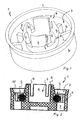
- a flow rate regulator 1 is shown in FIG is intended for installation in a sanitary water pipe.
- the Flow regulator 1 is used to regulate the through the water pipe flowing water volume to a defined maximum value.
- the flow rate regulator 1 has a regulator housing 2, in which a passage channel 3 for the water flowing through is provided.
- a central fixing tower 4 In the controller housing 2 there is a central fixing tower 4 provided. '
- an annular throttle body 5 is pushed onto the fixing tower 4 be that between itself and a part fixed to the housing limited a control gap, the passage cross section through under the pressure difference that forms when flowing through deforming throttle body 5 is changeable.
- the fixing bars 6 each have on their upstream free web end one that widens the cross-section of the web in the radial direction Formation 7 on.
- the provided on the fixing webs 6 Formations 7 are wedge-shaped in longitudinal section and have a radially outward widening in the sliding direction Thrust slope 8 on which the elastic throttle body 5 can be postponed.
- the fixing bars 6 are spring bars that can be deflected in a flexible manner designed. When sliding the throttle body 5 on the fixing webs 6 become the flexurally elastic fixing webs 6 deflected inwards such that the throttle body 5 quickly and can easily be pushed onto the fixing tower 4.
- the four fixing webs 6 carried by the fixing tower 4 are in evenly distributed over the circumference of the tower and through Longitudinal slots in the wall of the fixing tower separated.
- Fixing webs 6 deflected inwards until the throttle body 5 pushed over the undercut formed by the fixing webs 6 is. Due to the flexible design of the fixing bars 6 can also be designed as a plastic injection molded part Regulator housing 2 despite the intended undercut easily demoulded from a simple injection mold, without an expensive baking tool or an injection molding tool with plunge cores would be required.
- the fixing tower 4 arranged centrally in the controller housing 2 is slotted, the longitudinal slots the fixing tower 4 in the area make the fixing webs 6 flexible.
- This flexible elastic Design of the fixing tower 4 is a simple demolding possible from the injection mold. Also a plastic injection molded part designed controller housing can thus be demolded from the injection mold.
- the structure of the required injection molding tool is comparatively simple.
- the four longitudinal slots provided between the fixing webs 6 of the fixing tower 4 form four fixing points for the elastic throttle body 5.
- the fixing tower 4 for example, by six or eight Longitudinal slots divided into a corresponding number of fixing webs become.
- Step during assembly of the annular throttle body 5 only comparatively low assembly forces on the fixing tower 4, because this fixing tower when tightening the throttle body 5 can contract and "breathe” something.
- the assembly or Sloping slopes 8 on the fixing webs 6 ensure that the annular throttle bodies can be fed quickly from above can and throttle body 5 and controller housing 2 well Find.
- the combination reduces the effort of elasticity of the fixing tower 4 and suitable angle reached on the mounting or ramp slopes 8.
- An afterthought Bending or deforming on the controller housing 2 for fixation of the throttle body 5 is not required.
Landscapes
- Physics & Mathematics (AREA)
- General Physics & Mathematics (AREA)
- Engineering & Computer Science (AREA)
- Automation & Control Theory (AREA)
- Safety Valves (AREA)
- Sliding Valves (AREA)
- Injection Moulding Of Plastics Or The Like (AREA)
Abstract
Description
- Fig. 1
- einen perspektivisch dargestellten Durchflussmengenregler, der einen zentralen Fixierturm zum Aufschieben eines ringförmigen Drosselkörpers aus elastischem Material hat, und
- Fig. 2
- einen mit Figur 1 vergleichbaren Durchflussmengenregler in einem Längsschnitt, dessen Fixierturm von einem ringförmigen Drosselkörper aus elastischem Material umgriffen ist.
Claims (9)
- Durchflussmengenregler (1) mit einem Reglergehäuse (2), in dem in einem Durchtrittskanal ein ringförmiger Drosselkörper (5) aus elastischem Material vorgesehen ist, der auf einen Fixierturm (4) aufgeschoben ist und diesen umgreift, welcher Fixierturm (4) zumindest zwei entgegen der Schieberichtung orientierte Fixierstege (6) hat, die mit ihrem freien Stegende den Drosselkörper (5) sichernd hintergreifen, wobei der Drosselkörper (5) zwischen sich und zumindest einem gehäusefesten Teil einen Steuerspalt begrenzt, dessen Durchtrittsquerschnitt durch den sich unter der beim Durchströmen bildenden Druckdifferenz verformenden Drosselkörper (5) veränderbar ist, dadurch gekennzeichnet, dass die Fixierstege (6) als biegeelastisch einlenkbare Federstege ausgestaltet sind.
- Durchflussmengenregler nach Anspruch 1, dadurch gekennzeichnet, dass die Fixierstege (6) den Drosselkörper (5) jeweils mit einem am freien Stegende angeordneten Haltenocken oder dergleichen, den Stegquerschnitt erweiternder Ausformung (7) hintergreifen.
- Durchflussmengenregler nach Anspruch 1 oder 2, dadurch gekennzeichnet, dass der Fixierturm (4) zwei bis acht, vorzugsweise vier kreuzweise angeordnete Fixierstege (6) trägt.
- Durchflussmengenregler nach einem der Ansprüche 1 bis 3, dadurch gekennzeichnet, dass die Fixierstege (6) in gleichmäßigen Abständen über den Turmumfang verteilt sind.
- Durchflussmengenregler nach einem der Ansprüche 1 bis 4, dadurch gekennzeichnet, dass die Fixierstege (6) durch Längsschlitze in der Fixierturm-Wandung voneinander getrennt sind.
- Durchflussmengenregler nach einem der Ansprüche 1 bis 5, dadurch gekennzeichnet, dass die an den Fixierstegen (6) vorgesehenen Ausformungen (7) eine sich in Schieberichtung radial nach außen erweiternde Auflaufschräge (8) bilden.
- Durchflussmengenregler nach einem der Ansprüche 1 bis 6, dadurch gekennzeichnet, dass die Auflaufschrägen (8) gegenüber der Steg-Längsachse einen Winkel von 20° bis 30° einschließen.
- Durchflussmengenregler nach einem der Ansprüche 1 bis 7, dadurch gekennzeichnet, dass die Ausformungen (7) im Längsschnitt etwa keilförmig ausgestaltet sind.
- Durchflussmengenregler nach einem der Ansprüche 1 bis 8, dadurch gekennzeichnet, dass die Gehäuse-Umfangswandung mit dem Fixierturm (4) über radiale Verbindungsstege (9) verbunden ist und dass die Verbindungsstege (9) zwischen sich den Steuerspalt begrenzen.
Applications Claiming Priority (2)
| Application Number | Priority Date | Filing Date | Title |
|---|---|---|---|
| DE2002120287 DE10220287B4 (de) | 2002-05-07 | 2002-05-07 | Durchflußmengenregler |
| DE10220287 | 2002-05-07 |
Publications (2)
| Publication Number | Publication Date |
|---|---|
| EP1361490A1 true EP1361490A1 (de) | 2003-11-12 |
| EP1361490B1 EP1361490B1 (de) | 2009-01-14 |
Family
ID=29225078
Family Applications (1)
| Application Number | Title | Priority Date | Filing Date |
|---|---|---|---|
| EP20030006521 Expired - Lifetime EP1361490B1 (de) | 2002-05-07 | 2003-03-22 | Durchflussmengenregler |
Country Status (4)
| Country | Link |
|---|---|
| US (1) | US6695011B2 (de) |
| EP (1) | EP1361490B1 (de) |
| DE (2) | DE10220287B4 (de) |
| DK (1) | DK1361490T3 (de) |
Cited By (2)
| Publication number | Priority date | Publication date | Assignee | Title |
|---|---|---|---|---|
| EP2549156A1 (de) * | 2011-07-20 | 2013-01-23 | Flühs Drehtechnik GmbH | Ventiloberteil für Armaturen |
| CN105627017A (zh) * | 2014-11-08 | 2016-06-01 | 林文斌 | 带旁通通道的弹性体流量控制器 |
Families Citing this family (31)
| Publication number | Priority date | Publication date | Assignee | Title |
|---|---|---|---|---|
| DE10311501B4 (de) * | 2003-03-15 | 2011-06-16 | Neoperl Gmbh | Einbauteil zum Einsetzen in eine Gas- oder Flüssigkeitsleitung |
| DE10312854B4 (de) * | 2003-03-21 | 2014-08-28 | Neoperl Gmbh | Sanitäre Einsetzeinheit |
| US10619335B2 (en) | 2003-03-21 | 2020-04-14 | Neoperl Gmbh | Sanitary insert unit |
| US10669703B2 (en) | 2003-03-21 | 2020-06-02 | Neoperl Gmbh | Sanitary insert unit |
| US7222643B2 (en) * | 2004-10-21 | 2007-05-29 | Vernay Laboratories, Inc. | Internal post flow control |
| ITTO20040776A1 (it) | 2004-11-09 | 2005-02-09 | Gevipi Ag | Dispositivo per il controllo dinamico di un flusso di acqua |
| DE102005005433B4 (de) * | 2005-02-05 | 2006-10-19 | RST Gesellschaft für Wasserspartechnik mbH | Mengenregler |
| DE202005004196U1 (de) * | 2005-03-14 | 2006-07-27 | Neoperl Gmbh | Durchflussmengenregler |
| DE102006057787B3 (de) * | 2006-12-06 | 2008-05-29 | Neoperl Gmbh | Durchflussmengenregler |
| US8986253B2 (en) | 2008-01-25 | 2015-03-24 | Tandem Diabetes Care, Inc. | Two chamber pumps and related methods |
| US8408421B2 (en) | 2008-09-16 | 2013-04-02 | Tandem Diabetes Care, Inc. | Flow regulating stopcocks and related methods |
| CA2737461A1 (en) | 2008-09-19 | 2010-03-25 | Tandem Diabetes Care, Inc. | Solute concentration measurement device and related methods |
| AU2009338233A1 (en) * | 2009-01-23 | 2011-09-08 | Frankfurt Malta Holding Ltd. | Insert for water outlet |
| EP2724739B1 (de) | 2009-07-30 | 2015-07-01 | Tandem Diabetes Care, Inc. | Tragbares Infusionspumpensystem |
| US20120247588A1 (en) * | 2011-03-28 | 2012-10-04 | Tsai-Chen Yang | Flow rate stabilizer |
| DE202011100800U1 (de) * | 2011-05-17 | 2012-08-20 | Neoperl Gmbh | Durchflussmengenregler |
| US20130025719A1 (en) * | 2011-07-28 | 2013-01-31 | Tsai-Chen Yang | Flow rate stabilizer and connecting tube comprising the same |
| US8567445B2 (en) * | 2011-10-03 | 2013-10-29 | D.S. Magic Tech Llc | Water flow restriction device and method |
| US9180242B2 (en) | 2012-05-17 | 2015-11-10 | Tandem Diabetes Care, Inc. | Methods and devices for multiple fluid transfer |
| DE202012007719U1 (de) * | 2012-08-10 | 2013-11-12 | Neoperl Gmbh | Sanitäre Einsetzeinheit |
| CN103053387B (zh) * | 2013-01-11 | 2014-05-28 | 中国农业大学 | 一种毛管进口流量调节器 |
| US9173998B2 (en) | 2013-03-14 | 2015-11-03 | Tandem Diabetes Care, Inc. | System and method for detecting occlusions in an infusion pump |
| US9663929B2 (en) | 2014-08-21 | 2017-05-30 | Moen Incorporated | Plumbing fixture fitting |
| DE202015001757U1 (de) * | 2015-03-09 | 2016-06-10 | Neoperl Gmbh | Sanitäre Einsetzeinheit |
| CN204842000U (zh) * | 2015-07-06 | 2015-12-09 | 福建西河卫浴科技有限公司 | 一种具有止逆结构的限流装置 |
| ITUB20152864A1 (it) * | 2015-08-05 | 2017-02-05 | Giacomini Spa | Valvola di regolazione con bilanciamento dinamico della portata |
| US10208881B2 (en) * | 2016-04-13 | 2019-02-19 | Tsai-Chen Yang | Water-saving sheet and water-saving device having the same |
| DE202017101236U1 (de) * | 2017-03-03 | 2018-06-05 | Neoperl Gmbh | Durchflussmengenregler |
| US10077545B2 (en) * | 2017-04-12 | 2018-09-18 | Fujian Xihe Sanitary Ware Technology Co., Ltd. | Dual-adjustment flow limiting device |
| CN209054133U (zh) * | 2018-08-09 | 2019-07-02 | 厦门建霖健康家居股份有限公司 | 一种节水器 |
| DE202019101313U1 (de) * | 2019-03-08 | 2020-06-09 | Neoperl Gmbh | Strahlregler |
Citations (3)
| Publication number | Priority date | Publication date | Assignee | Title |
|---|---|---|---|---|
| DE1473130A1 (de) * | 1963-09-24 | 1968-11-07 | Martonair Ltd | Ventil |
| DE2060751A1 (de) * | 1970-12-10 | 1972-06-29 | Mannesmann & Keppel | Fluessigkeitsmengenregler |
| DE2131117A1 (de) * | 1971-06-23 | 1973-01-11 | Mannesmann & Keppel | Fluessigkeitsmengenregler |
Family Cites Families (26)
| Publication number | Priority date | Publication date | Assignee | Title |
|---|---|---|---|---|
| GB574310A (en) | 1944-01-31 | 1945-12-31 | Frederick George Lucas Becker | Improvements in or relating to apparatus for washing or mixing liquid with fibrous material |
| US2936788A (en) | 1955-04-26 | 1960-05-17 | Dole Valve Co | Flow control system |
| US2834379A (en) * | 1956-08-21 | 1958-05-13 | Scovill Manufacturing Co | Fluid flow control unit |
| US2960109A (en) | 1957-01-07 | 1960-11-15 | Gen Controls Co | Flow regulator |
| US2878836A (en) | 1957-05-13 | 1959-03-24 | Scovill Manufacturing Co | Two-piece flow control valve |
| US3189125A (en) | 1957-11-22 | 1965-06-15 | Hays Mfg Co | Flow control |
| US2989086A (en) | 1958-02-27 | 1961-06-20 | Dole Valve Co | Solid flow control valve |
| US3298394A (en) * | 1963-03-29 | 1967-01-17 | William J Chorkey | Check valve |
| US3216451A (en) * | 1963-10-07 | 1965-11-09 | Martonair Ltd | Annular sealing ring control valve |
| DE1650209A1 (de) | 1967-08-02 | 1970-09-10 | Stiebel Werke Gmbh & Co Dr | Vorrichtung zur selbsttaetigen Konstanthaltung einer Stroemungsmittel-Durchflussmenge |
| SE397736B (sv) * | 1970-12-10 | 1977-11-14 | Mannesmann & Keppel | Vetskemengdregulator |
| US3837363A (en) | 1972-12-20 | 1974-09-24 | P Meronek | Flow control device |
| US4000857A (en) | 1974-07-17 | 1977-01-04 | Moen Alfred M | Flow control aerator |
| DE2616566B2 (de) | 1976-04-14 | 1979-12-13 | Dieter Wildfang Kg, 7840 Muellheim | Durchflußbegrenzer für in Leitungen strömende Medien |
| DE3222548A1 (de) | 1982-06-16 | 1983-12-22 | Mannesmann + Keppel GmbH & Co KG, 8000 München | Fluessigkeitsmengenregler |
| US4562960A (en) * | 1983-03-14 | 1986-01-07 | Masco Corporation Of Indiana | Pressure responsive aerator |
| DE3442495A1 (de) | 1984-11-22 | 1986-05-22 | Hans Grohe Gmbh & Co Kg, 7622 Schiltach | Vorrichtung zur drosselnden durchflussbegrenzung in wasser-armaturen |
| DE3723559A1 (de) * | 1987-07-16 | 1989-01-26 | Reinhard Carl Mannesmann | Fluessigkeitsmengenregler |
| AU607873B2 (en) | 1990-02-02 | 1991-03-14 | Con-Serv Corporation Australia Pty Ltd | Adjustable arm |
| DE4023988C2 (de) | 1990-07-28 | 1997-02-13 | Ideal Standard | Sanitärarmatur |
| DE19603393A1 (de) * | 1996-01-31 | 1997-08-07 | Wildfang Dieter Gmbh | Durchflußmengenregler oder dergleichen Drossel |
| DE29601623U1 (de) | 1996-01-31 | 1996-03-14 | Dieter Wildfang GmbH, 79379 Müllheim | Durchflußmengenregler o.dgl. Drossel |
| DE19641233A1 (de) | 1996-10-07 | 1998-04-09 | Mueller A & K Gmbh Co Kg | In eine Flüssigkeitsleitung oder die Aufnahmebohrung einer Armatur einsetzbarer Mengenregler |
| DE19851151C2 (de) | 1998-11-06 | 2003-01-09 | Hansgrohe Ag | Durchflussbegrenzer für Sanitärarmaturen |
| DE10027986B4 (de) * | 2000-06-06 | 2007-02-22 | Neoperl Gmbh | Sanitäres Einbauteil |
| DE20022166U1 (de) | 2000-12-20 | 2001-06-21 | Huthmann, André, 27632 Midlum | Vorrichtung zum Regeln der Durchflußmenge eines fluiden Mediums |
-
2002
- 2002-05-07 DE DE2002120287 patent/DE10220287B4/de not_active Expired - Fee Related
-
2003
- 2003-03-04 US US10/379,233 patent/US6695011B2/en not_active Expired - Lifetime
- 2003-03-22 DK DK03006521T patent/DK1361490T3/da active
- 2003-03-22 DE DE50311077T patent/DE50311077D1/de not_active Expired - Lifetime
- 2003-03-22 EP EP20030006521 patent/EP1361490B1/de not_active Expired - Lifetime
Patent Citations (3)
| Publication number | Priority date | Publication date | Assignee | Title |
|---|---|---|---|---|
| DE1473130A1 (de) * | 1963-09-24 | 1968-11-07 | Martonair Ltd | Ventil |
| DE2060751A1 (de) * | 1970-12-10 | 1972-06-29 | Mannesmann & Keppel | Fluessigkeitsmengenregler |
| DE2131117A1 (de) * | 1971-06-23 | 1973-01-11 | Mannesmann & Keppel | Fluessigkeitsmengenregler |
Cited By (3)
| Publication number | Priority date | Publication date | Assignee | Title |
|---|---|---|---|---|
| EP2549156A1 (de) * | 2011-07-20 | 2013-01-23 | Flühs Drehtechnik GmbH | Ventiloberteil für Armaturen |
| WO2013010845A1 (de) * | 2011-07-20 | 2013-01-24 | Flühs Drehtechnik GmbH | Ventiloberteil für armaturen |
| CN105627017A (zh) * | 2014-11-08 | 2016-06-01 | 林文斌 | 带旁通通道的弹性体流量控制器 |
Also Published As
| Publication number | Publication date |
|---|---|
| EP1361490B1 (de) | 2009-01-14 |
| DE10220287A1 (de) | 2003-11-27 |
| US6695011B2 (en) | 2004-02-24 |
| US20030209278A1 (en) | 2003-11-13 |
| DK1361490T3 (da) | 2009-03-23 |
| DE10220287B4 (de) | 2004-09-16 |
| DE50311077D1 (de) | 2009-03-05 |
Similar Documents
| Publication | Publication Date | Title |
|---|---|---|
| DE10220287B4 (de) | Durchflußmengenregler | |
| DE2607689C2 (de) | Blindniet aus Kunststoff | |
| DE3742493C2 (de) | Befestigungselement und Verfahren zu dessen Anbringung | |
| DE4133478C2 (de) | Befestigungseinrichtung, insbesondere zum Befestigen einer Verkleidung an einer Unterstruktur | |
| DE19721314A1 (de) | Befestigungselement zur lösbaren Verbindung einer Verkleidung mit einem Träger | |
| DE19511580A1 (de) | Klipp | |
| DE19710489A1 (de) | Faltbares Schutzelement für Leitungen | |
| EP2712413B1 (de) | Anschlussvorrichtung zum anschliessen einer fluidleitung | |
| DE19830586A1 (de) | Tränkeventil | |
| DE1475035B2 (de) | Befestigungsvorrichtung | |
| DE3000645A1 (de) | Arretiervorrichtung | |
| DE68902278T2 (de) | Befestigung eines buendels von laenglichen gegenstaenden oder eines nichtkreisfoermigen laenglichen gegenstandes auf einer unterlage. | |
| EP1127224B1 (de) | Kugelgelenk | |
| DE102004053576B3 (de) | Schaltknauf und Schalthebel mit einem solchen Schaltknauf | |
| DE1947332U (de) | Befestigungselement aus zaehelastischem werkstoff. | |
| DE7807698U1 (de) | Rohrschelle | |
| DE69510631T2 (de) | Verfahren und Vorrichtung zum automatischen Zusammenbauen der Ventilkeile einer Brennkraftmaschine | |
| EP0167693B1 (de) | Reissverschlussschieber und Verfahren zu dessen Herstellung | |
| DE102019100946A1 (de) | Befestigungseinrichtung zum befestigen an einem plattenförmigen element | |
| DE1211032B (de) | Befestigungselement | |
| DE20207167U1 (de) | Durchflußmengenregler | |
| DE2456340A1 (de) | Steckverbinder | |
| DE19748623A1 (de) | Preßverbindung | |
| DE2152737A1 (de) | Endgarnitur fuer Schlaeuche | |
| DE3737178C2 (de) | Schnellbefestigungseinrichtung |
Legal Events
| Date | Code | Title | Description |
|---|---|---|---|
| PUAI | Public reference made under article 153(3) epc to a published international application that has entered the european phase |
Free format text: ORIGINAL CODE: 0009012 |
|
| AK | Designated contracting states |
Kind code of ref document: A1 Designated state(s): AT BE BG CH CY CZ DE DK EE ES FI FR GB GR HU IE IT LI LU MC NL PT RO SE SI SK TR |
|
| AX | Request for extension of the european patent |
Extension state: AL LT LV MK |
|
| 17P | Request for examination filed |
Effective date: 20031004 |
|
| RAP1 | Party data changed (applicant data changed or rights of an application transferred) |
Owner name: NEOPERL GMBH |
|
| AKX | Designation fees paid |
Designated state(s): CH DE DK GB IT LI |
|
| RIN1 | Information on inventor provided before grant (corrected) |
Inventor name: SOECHTIG, MICHAEL |
|
| GRAP | Despatch of communication of intention to grant a patent |
Free format text: ORIGINAL CODE: EPIDOSNIGR1 |
|
| GRAS | Grant fee paid |
Free format text: ORIGINAL CODE: EPIDOSNIGR3 |
|
| GRAA | (expected) grant |
Free format text: ORIGINAL CODE: 0009210 |
|
| AK | Designated contracting states |
Kind code of ref document: B1 Designated state(s): CH DE DK GB IT LI |
|
| REG | Reference to a national code |
Ref country code: GB Ref legal event code: FG4D Free format text: NOT ENGLISH |
|
| REG | Reference to a national code |
Ref country code: CH Ref legal event code: EP |
|
| REG | Reference to a national code |
Ref country code: CH Ref legal event code: NV Representative=s name: HANS RUDOLF GACHNANG PATENTANWALT |
|
| REF | Corresponds to: |
Ref document number: 50311077 Country of ref document: DE Date of ref document: 20090305 Kind code of ref document: P |
|
| REG | Reference to a national code |
Ref country code: DK Ref legal event code: T3 |
|
| PLBE | No opposition filed within time limit |
Free format text: ORIGINAL CODE: 0009261 |
|
| STAA | Information on the status of an ep patent application or granted ep patent |
Free format text: STATUS: NO OPPOSITION FILED WITHIN TIME LIMIT |
|
| 26N | No opposition filed |
Effective date: 20091015 |
|
| REG | Reference to a national code |
Ref country code: CH Ref legal event code: NV Representative=s name: GACHNANG AG PATENTANWAELTE, CH |
|
| PGFP | Annual fee paid to national office [announced via postgrant information from national office to epo] |
Ref country code: DK Payment date: 20190325 Year of fee payment: 17 |
|
| PGFP | Annual fee paid to national office [announced via postgrant information from national office to epo] |
Ref country code: GB Payment date: 20200325 Year of fee payment: 18 |
|
| PGFP | Annual fee paid to national office [announced via postgrant information from national office to epo] |
Ref country code: CH Payment date: 20200325 Year of fee payment: 18 |
|
| REG | Reference to a national code |
Ref country code: DK Ref legal event code: EBP Effective date: 20200331 |
|
| PG25 | Lapsed in a contracting state [announced via postgrant information from national office to epo] |
Ref country code: DK Free format text: LAPSE BECAUSE OF NON-PAYMENT OF DUE FEES Effective date: 20200331 |
|
| REG | Reference to a national code |
Ref country code: CH Ref legal event code: PL |
|
| GBPC | Gb: european patent ceased through non-payment of renewal fee |
Effective date: 20210322 |
|
| PG25 | Lapsed in a contracting state [announced via postgrant information from national office to epo] |
Ref country code: LI Free format text: LAPSE BECAUSE OF NON-PAYMENT OF DUE FEES Effective date: 20210331 Ref country code: CH Free format text: LAPSE BECAUSE OF NON-PAYMENT OF DUE FEES Effective date: 20210331 Ref country code: GB Free format text: LAPSE BECAUSE OF NON-PAYMENT OF DUE FEES Effective date: 20210322 |
|
| PGFP | Annual fee paid to national office [announced via postgrant information from national office to epo] |
Ref country code: DE Payment date: 20220303 Year of fee payment: 20 |
|
| PGFP | Annual fee paid to national office [announced via postgrant information from national office to epo] |
Ref country code: IT Payment date: 20220331 Year of fee payment: 20 |
|
| REG | Reference to a national code |
Ref country code: DE Ref legal event code: R071 Ref document number: 50311077 Country of ref document: DE |