EP1361099A2 - Antriebsstranglagerung - Google Patents
Antriebsstranglagerung Download PDFInfo
- Publication number
- EP1361099A2 EP1361099A2 EP03251895A EP03251895A EP1361099A2 EP 1361099 A2 EP1361099 A2 EP 1361099A2 EP 03251895 A EP03251895 A EP 03251895A EP 03251895 A EP03251895 A EP 03251895A EP 1361099 A2 EP1361099 A2 EP 1361099A2
- Authority
- EP
- European Patent Office
- Prior art keywords
- power train
- sub
- skeleton member
- support
- support bracket
- Prior art date
- Legal status (The legal status is an assumption and is not a legal conclusion. Google has not performed a legal analysis and makes no representation as to the accuracy of the status listed.)
- Granted
Links
Images


Classifications
-
- B—PERFORMING OPERATIONS; TRANSPORTING
- B60—VEHICLES IN GENERAL
- B60K—ARRANGEMENT OR MOUNTING OF PROPULSION UNITS OR OF TRANSMISSIONS IN VEHICLES; ARRANGEMENT OR MOUNTING OF PLURAL DIVERSE PRIME-MOVERS IN VEHICLES; AUXILIARY DRIVES FOR VEHICLES; INSTRUMENTATION OR DASHBOARDS FOR VEHICLES; ARRANGEMENTS IN CONNECTION WITH COOLING, AIR INTAKE, GAS EXHAUST OR FUEL SUPPLY OF PROPULSION UNITS IN VEHICLES
- B60K5/00—Arrangement or mounting of internal-combustion or jet-propulsion units
- B60K5/12—Arrangement of engine supports
- B60K5/1275—Plastically deformable supports
-
- B—PERFORMING OPERATIONS; TRANSPORTING
- B62—LAND VEHICLES FOR TRAVELLING OTHERWISE THAN ON RAILS
- B62D—MOTOR VEHICLES; TRAILERS
- B62D21/00—Understructures, i.e. chassis frame on which a vehicle body may be mounted
-
- B—PERFORMING OPERATIONS; TRANSPORTING
- B62—LAND VEHICLES FOR TRAVELLING OTHERWISE THAN ON RAILS
- B62D—MOTOR VEHICLES; TRAILERS
- B62D21/00—Understructures, i.e. chassis frame on which a vehicle body may be mounted
- B62D21/15—Understructures, i.e. chassis frame on which a vehicle body may be mounted having impact absorbing means, e.g. a frame designed to permanently or temporarily change shape or dimension upon impact with another body
Definitions
- the present invention relates to a power train support apparatus for supporting a power train including an engine, a transaxle and the like of a vehicle.
- JP7164894 discloses a power train support apparatus (referred to as "ENGINE SUPPORT STRUCTURE" in its English abstract).
- United States Patent No. 6,131,685 ⁇ equivalent of Japanese Patent Unexamined Publication No. Heisei 9 (1997)-240291 ⁇ discloses a power train support apparatus (referred to as "POWER TRAIN SUPPORTING APPARATUS").
- the power train is supposed to drop from a third engine mount in accordance with the curved portion ⁇ of the sub-side member ⁇ bending downward in substantially a head-on collision of the vehicle.
- the power train supporting apparatus according to United States Patent No. 6,131,685 has the following limitations in terms of configuration and disposing method:
- a power train support apparatus for supporting a power train which is adapted to be dropped with a load greater than or equal to a given value thereof applied substantially in a fore-and-aft direction of a vehicular body.
- the power train support apparatus comprises: a support bracket mounted to the power train.
- the support bracket comprises an upper connection at least which is suspended with a support member of the vehicular body.
- the support bracket is formed with a breakable portion which is breakable with a load greater than or equal to a given value thereof applied substantially downward from the upper connection.
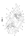
- Fig. 1 is an overall view of a power train support apparatus 3 in combination with a vehicular body support member 6, according to an embodiment of the present invention.
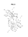
- Fig. 2 is an enlarged view of a first support bracket 4.
- Fig. 3 is an enlarged view of a second support bracket 5.
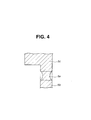
- Fig. 4 is a cross section of a breakable portion 5e, taken along lines IV-IV in Fig. 3.
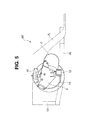
- Fig. 5 is a side view of the power train support apparatus, according to the embodiment of the present invention.
- Fig. 6 shows an operation of the power train support apparatus in substantially a head-on collision of a vehicle.
- a power train support apparatus which is applied to a front engine and front wheel drive vehicle, according to an embodiment of the present invention.
- an engine 1 as a driving source of revolution.
- a transaxle 2 which is a transmission unitedly connected in line with an output side of engine 1.
- Engine 1 (located sidewise) and transaxle 2 constitute a power train 3.
- a first support bracket 4 is mounted on engine side of power train 3, while a second support bracket 5 is mounted on transaxle side of power train 3.
- Each of first support bracket 4 and second support bracket 5 is suspended with a vehicular body support member 6.
- first support bracket 4 has a support bracket body 4b, an upper connection 4c, a lower connection 4d, and a breakable portion 4e which are so united as to constitute first support bracket 4.
- support bracket body 4b is formed with a through hole 4a.
- Upper connection 4c connected to a first suspension member 9 is positioned higher than support bracket body 4b.
- Lower connection 4d connected to a lower connecting member 11 is positioned lower than support bracket body 4b.
- Breakable portion 4e is formed lower than upper connection 4c, and higher than a portion mounted to power train 3.
- Breakable portion 4e is breakable with a load (greater than or equal to its given value) applied downward from upper connection 4c.
- Support bracket body 4b has a first face which is tightened, by means of a bolt and the like, to a position higher than a protrusion on a side face of power train 3.
- Support bracket body 4b further has a mount plate 4b'.
- Mount plate 4b' bends substantially perpendicularly from the first face of support bracket body 4b.
- mount plate 4b' has a face contacting a rear face of power train 3. With this, mount plate 4b' is tightened, by means of a bolt and the like, to power train 3.
- upper connection 4c is formed with a through hole 4f -- to be described afterward.
- Upper connection 4c is shaped substantially into a tongue.
- lower connection 4d is formed with a through hole 4g -- to be described afterward.
- Breakable portion 4e is a cutout which is formed in the following manner:
- Breakable portion 4e is so designed as to be broken with the downward load (for example, about 25 kN) applied to breakable portion 4e.
- second support bracket 5 has a support bracket body 5b, an upper connection 5c, a lower connection 5d, and a breakable portion 5e which are so united as to constitute second support bracket 5.
- support bracket body 5b is formed with a plurality of through-holes 5a.
- Support bracket body 5b is shaped substantially into a plate.
- Upper connection 5c connected to second suspension member 10 is positioned higher than support bracket body 5b.
- Upper connection 5c is disposed substantially in the horizontal center above support bracket body 5b in such a manner as to protrude upward.
- Lower connection 5d connected to a lower connecting member 12 is positioned lower than support bracket body 5b. With respect to a forward direction of the vehicle, lower connection 5d protrudes leftward.
- Broken portion 5e is formed lower than upper connection 5c, and higher than a portion mounted to power train 3. In other words, broken portion 5e is formed in an area covered by an upper end of support bracket body 5b.
- Breakable portion 5e is breakable with a load (greater than or equal to its given value) applied downward to support bracket body 5b.
- upper connection 5c is formed with a through hole 5f -- to be described afterward.
- Upper connection 5c is a block which is shaped substantially into a tongue in plan view.
- lower connection 5d protrudes substantially perpendicularly relative to support bracket body 5b.
- lower connection 5d is formed with a through hole 5g -- to be described afterward.
- lower connection 5d is shaped substantially into a triangle pole.
- lower connection 5d has a pair of reinforcing ribs 5d' opposing each other.
- Breakable portion 5e is a cutout which is formed in the following manner:
- breakable portion 5e is so designed as to be broken with the downward load (for example, about 25 kN) applied to breakable portion 5e.
- a strength connecting first suspension member 9 to upper connection 4c is designed higher than a strength of breakable portion 4e disposed between upper connection 4c and support bracket body 4b.
- a strength connecting lower connecting member 11 to lower connection 4d is designed higher than the strength of breakable portion 4e disposed between upper connection 4c and support bracket body 4b.
- a strength connecting second suspension member 10 to upper connection 5c is designed higher than a strength of breakable portion 5e disposed between upper connection 5c and support bracket body 5b.
- a strength connecting lower connecting member 12 to lower connection 5d is designed higher than the strength of breakable portion 5e disposed between upper connection 5c and support bracket body 5b.
- vehicular body support member 6 is constituted of: a pair of a front right member 7R and a front left member 7L, a sub-frame 8, first suspension member 9, second suspension member 10, lower connecting member 11, and lower connecting member 12.
- Each of front right member 7R and front left member 7L is a main skeleton member extending in a fore-and-aft direction of the vehicular body.
- Sub-frame 8 is disposed lower than front right member 7R and front left member 7L. Moreover, sub-frame 8 is a sub-skeleton member which bends downward with a load (greater than or equal to its given value) applied in the fore-and-aft direction of the vehicular body. Sub-frame 8 is shaped substantially into a girder in plan view.
- First suspension member 9 is fixed to front right member 7R in such a manner as to suspend an upper side of first support bracket 4.
- Second suspension member 10 is fixed to front left member 7L in such a manner as to suspend an upper side of second support bracket 5.
- Lower connecting member 11 is fixed to sub-frame 8, and connects to a lower side of first support bracket 4.
- Lower connecting member 12 is fixed to sub-frame 8, and connects to a lower side of second support bracket 5.
- Sub-frame 8 is constituted of a right sub-frame 8R and a left sub-frame 8L. More specifically, each of right sub-frame 8R and left sub-frame 8L has a front end which mates with a front end of one of respective front right member 7R and front left member 7L. Each of right sub-frame 8R and left sub-frame 8L is deflected inward in a rearward direction of the vehicular body, relative to one of respective front right member 7R and front left member 7L.
- sub-frame 8 is constituted of a front sub-frame 8Fr and a rear sub-frame 8Re. More specifically, front sub-frame 8Fr connects the front end of right sub-frame 8R to the front end of left sub-frame 8L, while rear sub-frame 8Re connects a rear end of right sub-frame 8R to a rear end of left sub-frame 8L.
- left sub-frame 8L (likewise, right sub-frame 8R) has the front end inclined upward from substantially a center thereof.
- the front end of left sub-frame 8L connects to the front end of front left member 7L by way of a connecting member 13.
- each of right sub-frame 8R and left sub-frame 8L connects to a cross-member (not shown).
- each of right sub-frame 8R and left sub-frame 8L is formed with a cutout 14.
- cutout 14 may encourage each of right sub-frame 8R and left sub-frame 8L to bend downward.
- First support member 6A is constituted of front right member 7R, right sub-frame 8R, first suspension member 9, and lower connecting member 11.
- second support member 6B is constituted of front left member 7L, left sub-frame 8L, second suspension member 10, and lower connecting member 12.
- first suspension member 9 is constituted of a support member body 9a and connecting shaft 9b.
- Support member body 9a shaped substantially into a mountain is tightened to an upper face of front right member 7R by means of a bolt and the like.
- connecting shaft 9b is inserted into through hole 4f of upper connection 4c of first support bracket 4.
- lower connecting member 11 is tightened rearward relative to cutout 14 on an upper face of right sub-frame 8R.
- lower connecting member 11 is constituted of a support plate 11a, a rod 11b (connecting lever), and connecting shaft 11c.
- Support plate 11a for supporting rod 11b has a pair of plates which are opposed to each other in such a manner that support plate 11a forms substantially a Japanese katakana character " " or a rectangular English alphabet "U”.
- a lower end of rod 11b is formed with a through-hole 11d. Inserting connecting shaft 11c into through-hole 4g of lower connection 4d of first support bracket 4 can fix an upper end of rod 11b.
- second suspension member 10 is constituted of a support plate 10a, a support block 10b, and connecting shaft 10c.
- Support plate 10a abuts on an inside face of front left member 7L.
- support plate 10a is formed with a plurality of through-holes 10d.
- Support block 10b is united with support plate 10a.
- connecting shaft 10c is inserted into support block 10b and through hole 5f of upper connection 5c of second support bracket 5.
- Lower connecting member 12 is constituted of an insulator 12a, a mount portion 12b, and connecting shaft 12c.
- Insulator 12a shaped substantially into a circular column incorporates an elastic body for reducing vibration transmitted from power train 3 to left sub-frame 8L.
- Mount potion 12b is disposed on a side face of insulator 12a.
- mount portion 12b is formed with a through-hole 12d. Inserting connecting shaft 12c into insulator 12a and through hole 5g of lower connection 5d of second support bracket 5 can fix lower connecting member 12 to second support bracket 5.
- FIG. 6 is operation of the power train support apparatus in substantially a head-on collision of the vehicle, according to the embodiment of the present invention.
- An excessive load caused to substantially a head of the vehicle and applied rearward may be divided into two, namely, one is applied to front left member 7L and the other is applied to left sub-frame 8L.
- Front left member 7L is smashed axially (horizontally in Fig. 6).
- left sub-frame 8L having the front end inclined upward from substantially the center thereof and formed with cutout 14 on substantially the center thereof (Fig. 5) may bend downward to a great extent in such a manner that cutout 14 (apex) is displaced downward.
- lower connecting member 12 connected to left sub-frame 8L starts the downward displacement in accordance with the left sub-frame 8L bending downward, thereby causing a great downward load (tension) to second support bracket 5 which is supported with second suspension member 10 from upper portion.
- left sub-frame 8L further bends downward.
- the downward load (tension) concentrated on breakable portion 5e reaches its given value (for example, 25 kN)
- breakable portion 5e may be broken, to thereby release support bracket body 5b from upper connection 5c connected to second suspension member 10.
- second support bracket 5 and power train 3 (connected to second support bracket 5) can be dropped smoothly in accordance with the downward displacement of left sub-frame 8L, then, moved rearward in such a manner as to dive under a floor of the vehicular body.
- the point 1 and the point 2 can protect legs of a front seat occupant.
- the breakage mechanism for dropping power train 3 disposed on first support bracket 4 and second support bracket 5 can greatly contribute to deregulation of the following:
- first suspension member 9 and second suspension member 10 are described as follows:
- first suspension member 9 and second suspension member 10 can be free from limitation on configuration, and limitation on disposing method relative to respective front right member 7R and front left member 7L.
- any other connecting member can replace lower connecting member 11 and lower connecting member 12, and right sub-frame 8R and left sub-frame 8L can be free from any limitation, resulting in greatly improved free layout in the engine room.
- a suspension member and a lower connecting member which are combined with a support bracket can be selected based on the following points:
- first support bracket 4 and second support bracket 5 With upper connection 4c and upper connection 5c united respectively with support bracket body 4b and support bracket body 5b, while lower connection 4d and lower connection 5d united respectively with support bracket body 4b and support bracket body 5b, respective first support bracket 4 and second support bracket 5 can be mounted on power train 3 with ease.
- the power train support apparatus has the following construction:
- Rod 11b cheaper than insulator 12a can contribute to preventing cost increase.
- insulator 12a for lower connecting member 12 on transaxle side especially when the power support apparatus is applied to the front-drive vehicle with engine 1 located sidewise, can improve vibration-proof of the members of the vehicular body:
- the downward load can be applied with ease to breakable portion 4e and breakable portion 5e since breakable portion 4e and breakable portion 5e are formed on the upper part of respective first support bracket 4 and second support bracket 5.
- breakable portion 4e and breakable portion 5e is the cutout formed in the following manner:
- the above construction of the cutout can evenly break each of breakable portion 4e and breakable portion 5e in the following states:
- the above construction of the cutout can prevent an unexpected breakage which may be caused by comparatively a light load attributable to the vehicular body riding on a curbstone and the like.
- the power train support apparatus has the following construction and operation:
- power train 3 can be assuredly dropped when the excessive load is applied rearward to the head of the vehicle.
- the above construction and operation of the power train support apparatus can deregulate the limitation on the configuration and the disposing method of first suspension member 9, second suspension member 10, lower connecting member 11, and lower connecting member 12.
- the power train support apparatus according to the embodiment is applied to the front engine and front wheel drive vehicle (FF).
- the present invention is, however, not limited to the above.
- the power train support apparatus under the present invention is applicable to other vehicles including a front engine and rear wheel drive vehicle (FR), a rear engine and rear wheel drive vehicle (RR).
- the power train support apparatus under the present invention is applicable to an electric vehicle with an electric motor as a driving source of revolution.
- breakable portion 4e, 5e is the cutout which is the area partly cut between the support bracket body 4b, 5b and the upper connection 4c, 5c.
- the present invention Reducing thickness partly between the support bracket body 4b, 5b and the upper connection 4c, 5c, or forming a plurality of through-holes along the breakable portion 4e, 5e is allowed. What is of importance is to assuredly break the area between the support bracket body 4b, 5b and the upper connection 4c, 5c with the load applied to the given position.
- breakable portion 4e, 5e is arbitrary in terms of configuration.
- power train 3 is supported at two portions, namely, on transaxle side and engine side.
- the present invention is, however, not limited to the above. Supporting power train 3 at the center, or at three portions or more is allowed. What is of importance is to assuredly move power train 3 downward when sub-frame 8 is bent downward attributable to the substantially head-on collision of the vehicle. In sum, the number of portions for supporting power train 3 is arbitrary.
- rod 11b is used for lower connecting member 11 on engine side for preventing the cost increase.
- the present invention is, however, not limited to the above. Improving vibration-proof of power train 3 preferably uses an insulator for lower connecting member 11 on engine side, and more preferably, for first suspension member 9 and second suspension member 10.
- lower connection 4d and lower connection 5d of respective first support bracket 4 and second support bracket 5 are connected to respective lower connecting member 11 and lower connecting member 12.
- the present invention is, however, not limited to the above. With lower connection 4d and lower connection 5d omitted, the following construction is allowed:
Landscapes
- Engineering & Computer Science (AREA)
- Chemical & Material Sciences (AREA)
- Combustion & Propulsion (AREA)
- Transportation (AREA)
- Mechanical Engineering (AREA)
- Arrangement Or Mounting Of Propulsion Units For Vehicles (AREA)
- Body Structure For Vehicles (AREA)
- Electric Propulsion And Braking For Vehicles (AREA)
Applications Claiming Priority (2)
| Application Number | Priority Date | Filing Date | Title |
|---|---|---|---|
| JP2002135810 | 2002-05-10 | ||
| JP2002135810A JP4023208B2 (ja) | 2002-05-10 | 2002-05-10 | パワートレイン支持装置 |
Publications (3)
| Publication Number | Publication Date |
|---|---|
| EP1361099A2 true EP1361099A2 (de) | 2003-11-12 |
| EP1361099A3 EP1361099A3 (de) | 2004-11-17 |
| EP1361099B1 EP1361099B1 (de) | 2008-05-28 |
Family
ID=29244232
Family Applications (1)
| Application Number | Title | Priority Date | Filing Date |
|---|---|---|---|
| EP03251895A Expired - Lifetime EP1361099B1 (de) | 2002-05-10 | 2003-03-26 | Antriebsstranglagerung |
Country Status (4)
| Country | Link |
|---|---|
| US (1) | US7040446B2 (de) |
| EP (1) | EP1361099B1 (de) |
| JP (1) | JP4023208B2 (de) |
| DE (1) | DE60321264D1 (de) |
Cited By (9)
| Publication number | Priority date | Publication date | Assignee | Title |
|---|---|---|---|---|
| DE10354639A1 (de) * | 2003-11-22 | 2005-08-04 | Bayerische Motoren Werke Ag | Aggregate-Befestigungseinrichtung für ein Kraftfahrzeug |
| EP2476603A3 (de) * | 2011-01-14 | 2013-05-15 | Aston Martin Lagonda Limited | Komponenten für Kraftfahrzeugunfallstruktur |
| FR3001942A1 (fr) * | 2013-02-14 | 2014-08-15 | Peugeot Citroen Automobiles Sa | Berceau moteur a fixation souple et incassable en cas de choc frontal |
| ITTO20130474A1 (it) * | 2013-06-07 | 2014-12-08 | Fiat Group Automobiles Spa | Autoveicolo provvisto di un sistema di sgancio per staccare una traversa nel vano motore in caso d'urto frontale |
| EP3181390A1 (de) * | 2015-12-17 | 2017-06-21 | Audi Ag | Aggregatelagerung für ein fahrzeug-antriebsaggregat |
| WO2020126599A1 (fr) * | 2018-12-20 | 2020-06-25 | Renault S.A.S | Véhicule automobile comprenant un support de moteur et un châssis |
| GB2587624A (en) * | 2019-10-01 | 2021-04-07 | Caterpillar Inc | Mounting system |
| EP3808635A1 (de) | 2019-10-17 | 2021-04-21 | FCA Italy S.p.A. | Kraftfahrzeug mit einem freisetzungssystem zum abkoppeln eines querträgers im motorraum im fall eines frontalunfalls |
| RU2793160C2 (ru) * | 2018-12-20 | 2023-03-29 | Рено С.А.С | Автотранспортное средство, содержащее опору двигателя и раму |
Families Citing this family (37)
| Publication number | Priority date | Publication date | Assignee | Title |
|---|---|---|---|---|
| JP3900048B2 (ja) * | 2001-11-19 | 2007-04-04 | 日産自動車株式会社 | 車体前部構造 |
| DE10328170A1 (de) * | 2003-06-24 | 2005-01-13 | Daimlerchrysler Ag | Kraftfahrzeug mit absenkbarem Antriebsaggregat |
| JP4231473B2 (ja) * | 2004-10-19 | 2009-02-25 | 本田技研工業株式会社 | ステアリングギヤボックス取付構造 |
| FR2884181B1 (fr) * | 2005-04-11 | 2007-06-15 | Renault Sas | Ensemble de moteur d'un vehicule |
| JP4783793B2 (ja) * | 2005-09-27 | 2011-09-28 | オートリブ ディベロップメント エービー | 車両の衝撃低減構造 |
| US20070221430A1 (en) * | 2006-03-21 | 2007-09-27 | Allison Kenneth M Sr | Modular automobile system and method |
| JP4832171B2 (ja) * | 2006-06-06 | 2011-12-07 | 富士重工業株式会社 | 車両の前部構造 |
| DE102006041094B4 (de) * | 2006-09-01 | 2015-04-02 | Audi Ag | Lagervorrichtung zur Lagerung einer Fahrzeugkomponente an einer Karosserie eines Fahrzeugs |
| KR20080042389A (ko) * | 2006-11-09 | 2008-05-15 | 현대자동차주식회사 | 자동차의 유체형 엔진 마운트용 스토퍼 |
| JP4956794B2 (ja) * | 2007-04-03 | 2012-06-20 | 日産自動車株式会社 | サスペンション取り付け構造 |
| EP1977956B1 (de) * | 2007-04-03 | 2012-08-29 | Nissan Motor Co., Ltd. | Installationsstruktur und Verfahren zur Fahrzeugaufhängung |
| JP5136229B2 (ja) * | 2008-06-09 | 2013-02-06 | 日産自動車株式会社 | パワートレイン支持構造 |
| US7762619B2 (en) * | 2008-07-29 | 2010-07-27 | Ford Global Technologies, Llc | Sequential crash hinges in automotive frame rails |
| JP4585585B2 (ja) * | 2008-08-06 | 2010-11-24 | 本田技研工業株式会社 | 車体構造 |
| US8132640B2 (en) * | 2008-08-07 | 2012-03-13 | Honda Motor Co., Ltd. | Frangible mount for a vehicle differential |
| US7975787B2 (en) * | 2008-11-06 | 2011-07-12 | Clark Equipment Company | Low mount three point engine and pump mounting |
| US8215444B2 (en) * | 2009-07-09 | 2012-07-10 | Ford Global Technologies | Roll restrictor system for an automotive powertrain |
| DE102009034905A1 (de) * | 2009-07-28 | 2011-02-03 | GM Global Technology Operations, Inc., Detroit | Kraftfahrzeug-Vorderbau und Verfahren zur Herstellung eines Kraftfahrzeug-Vorderbaus |
| KR101244708B1 (ko) | 2010-10-07 | 2013-03-18 | 기아자동차주식회사 | 측면 조립형 트랜스미션 마운트 |
| TWI435813B (zh) * | 2011-06-28 | 2014-05-01 | Metal Ind Res & Dev Ct | Electric vehicle power module fixed bracket |
| JP5929435B2 (ja) * | 2012-04-04 | 2016-06-08 | スズキ株式会社 | ハイブリッド車両用動力装置 |
| EP3023281B1 (de) * | 2013-07-18 | 2017-04-05 | Nissan Motor Co., Ltd. | Hybridfahrzeug |
| JP5696955B2 (ja) * | 2013-07-30 | 2015-04-08 | 三菱自動車工業株式会社 | 車両用の回転電機 |
| US9158868B2 (en) * | 2013-08-22 | 2015-10-13 | GM Global Technology Operations LLC | Vehicle powertrain mounting system and method of designing same |
| JP6151237B2 (ja) * | 2014-11-17 | 2017-06-21 | 本田技研工業株式会社 | サブフレーム構造 |
| JP6518168B2 (ja) * | 2015-08-26 | 2019-05-22 | 本田技研工業株式会社 | モータ取付構造 |
| JP6529888B2 (ja) * | 2015-10-22 | 2019-06-12 | 本田技研工業株式会社 | 燃料電池スタックのマウント構造 |
| US9738148B1 (en) * | 2016-02-17 | 2017-08-22 | GM Global Technology Operations LLC | Stud assembly |
| JP6658500B2 (ja) * | 2016-12-26 | 2020-03-04 | トヨタ自動車株式会社 | 燃料電池の搭載構造 |
| KR102258481B1 (ko) * | 2017-03-27 | 2021-06-01 | 현대자동차주식회사 | 엔진 마운팅 구조 |
| US10059380B1 (en) * | 2017-08-08 | 2018-08-28 | Ford Global Technologies, Llc | Mounting an accessory to a frame member |
| GB2569582B (en) | 2017-12-20 | 2020-06-17 | Ford Global Tech Llc | A powertrain support mount assembly |
| JP2019188884A (ja) * | 2018-04-19 | 2019-10-31 | トヨタ自動車株式会社 | 燃料電池自動車 |
| CN112009568B (zh) * | 2019-05-30 | 2022-10-28 | 马自达汽车株式会社 | 车辆的动力系支撑结构 |
| JP7281102B2 (ja) * | 2019-05-30 | 2023-05-25 | マツダ株式会社 | 車両のパワートレイン支持方法および支持構造 |
| JP7259667B2 (ja) * | 2019-09-17 | 2023-04-18 | トヨタ自動車株式会社 | 燃料電池スタックの車両搭載構造及び車両搭載方法 |
| KR20220090986A (ko) * | 2020-12-23 | 2022-06-30 | 현대자동차주식회사 | 연료 전지 차량 |
Citations (3)
| Publication number | Priority date | Publication date | Assignee | Title |
|---|---|---|---|---|
| JPH07164894A (ja) | 1993-12-14 | 1995-06-27 | Suzuki Motor Corp | エンジン支持構造 |
| US6131685A (en) | 1995-12-27 | 2000-10-17 | Toyota Jidosha Kabushiki Kaisha | Power train supporting apparatus |
| JP2002135810A (ja) | 2000-10-24 | 2002-05-10 | Institute For Welcome System Ltd | 携帯電話等の移動体通信端末とテレビ受像機およびテレビ録画装置の遠隔操作装置を一体化することで効率的テレビ番組視聴、視聴率調査、電子商取引を円滑に行う機構および方法 |
Family Cites Families (11)
| Publication number | Priority date | Publication date | Assignee | Title |
|---|---|---|---|---|
| DE2056102A1 (de) * | 1970-11-14 | 1972-05-18 | Volkswagenwerk Ag, 3180 Wolfsburg | Anordnung eines Antriebsaggregates im Vorderwagen eines Kraftfahrzeuges |
| FR2120386A5 (de) * | 1970-12-31 | 1972-08-18 | Peugeot & Renault | |
| DE3117378C2 (de) * | 1981-05-02 | 1986-10-23 | Dr.Ing.H.C. F. Porsche Ag, 7000 Stuttgart | Aufhängung für ein frontseitig, insbesondere querliegend angeordnetes Antriebsaggregat eines Kraftfahrzeugs |
| DE3224935C2 (de) * | 1982-07-03 | 1984-04-19 | Adam Opel AG, 6090 Rüsselsheim | Antriebsaggregat für Kraftfahrzeuge |
| DE4326396C2 (de) * | 1993-08-06 | 2001-07-26 | Daimler Chrysler Ag | Kraftwagen mit einem in einem spitzen Winkel gegen die Horizontale geneigten Antriebsmotor |
| JP3417811B2 (ja) * | 1997-09-26 | 2003-06-16 | ダイハツ工業株式会社 | パワープラントのマウント構造 |
| GB2329877A (en) * | 1997-10-01 | 1999-04-07 | Rover Group | Vehicle subframe attached to a structure by non-frangible and frangible mountings |
| JP2002002310A (ja) * | 2000-06-15 | 2002-01-09 | Mitsubishi Motors Corp | パワープラントの支持構造 |
| JP2002012040A (ja) * | 2000-06-29 | 2002-01-15 | Mitsubishi Motors Corp | パワープラントの支持構造 |
| JP4054172B2 (ja) * | 2000-10-23 | 2008-02-27 | 株式会社神戸製鋼所 | エンジンマウント |
| JP3575439B2 (ja) * | 2001-06-04 | 2004-10-13 | 日産自動車株式会社 | 自動車のパワーユニット配置構造 |
-
2002
- 2002-05-10 JP JP2002135810A patent/JP4023208B2/ja not_active Expired - Lifetime
-
2003
- 2003-03-26 EP EP03251895A patent/EP1361099B1/de not_active Expired - Lifetime
- 2003-03-26 DE DE60321264T patent/DE60321264D1/de not_active Expired - Lifetime
- 2003-04-03 US US10/405,629 patent/US7040446B2/en not_active Expired - Lifetime
Patent Citations (3)
| Publication number | Priority date | Publication date | Assignee | Title |
|---|---|---|---|---|
| JPH07164894A (ja) | 1993-12-14 | 1995-06-27 | Suzuki Motor Corp | エンジン支持構造 |
| US6131685A (en) | 1995-12-27 | 2000-10-17 | Toyota Jidosha Kabushiki Kaisha | Power train supporting apparatus |
| JP2002135810A (ja) | 2000-10-24 | 2002-05-10 | Institute For Welcome System Ltd | 携帯電話等の移動体通信端末とテレビ受像機およびテレビ録画装置の遠隔操作装置を一体化することで効率的テレビ番組視聴、視聴率調査、電子商取引を円滑に行う機構および方法 |
Cited By (14)
| Publication number | Priority date | Publication date | Assignee | Title |
|---|---|---|---|---|
| DE10354639A1 (de) * | 2003-11-22 | 2005-08-04 | Bayerische Motoren Werke Ag | Aggregate-Befestigungseinrichtung für ein Kraftfahrzeug |
| US9039070B2 (en) | 2011-01-14 | 2015-05-26 | Aston Martin Lagonda Limited | Crash load absorption structures for motor vehicles |
| EP2476603A3 (de) * | 2011-01-14 | 2013-05-15 | Aston Martin Lagonda Limited | Komponenten für Kraftfahrzeugunfallstruktur |
| FR3001942A1 (fr) * | 2013-02-14 | 2014-08-15 | Peugeot Citroen Automobiles Sa | Berceau moteur a fixation souple et incassable en cas de choc frontal |
| US9150251B2 (en) | 2013-06-07 | 2015-10-06 | Fiat Group Automobiles S.P.A. | Motor vehicle provided with a release system to uncouple a cross member in the engine compartment in the event of a front crash |
| EP2810854A1 (de) | 2013-06-07 | 2014-12-10 | Fiat Group Automobiles S.p.A. | Kraftfahrzeug mit einem Freisetzungssystem zum Abkoppeln eines Querträgers im Motorraum im Fall eines Frontalunfalls |
| ITTO20130474A1 (it) * | 2013-06-07 | 2014-12-08 | Fiat Group Automobiles Spa | Autoveicolo provvisto di un sistema di sgancio per staccare una traversa nel vano motore in caso d'urto frontale |
| EP3181390A1 (de) * | 2015-12-17 | 2017-06-21 | Audi Ag | Aggregatelagerung für ein fahrzeug-antriebsaggregat |
| US10118476B2 (en) | 2015-12-17 | 2018-11-06 | Audi Ag | Engine mount assembly for a vehicle drive unit |
| WO2020126599A1 (fr) * | 2018-12-20 | 2020-06-25 | Renault S.A.S | Véhicule automobile comprenant un support de moteur et un châssis |
| FR3090552A1 (fr) * | 2018-12-20 | 2020-06-26 | Renault S.A.S | Véhicule automobile comprenant un support de moteur et un châssis |
| RU2793160C2 (ru) * | 2018-12-20 | 2023-03-29 | Рено С.А.С | Автотранспортное средство, содержащее опору двигателя и раму |
| GB2587624A (en) * | 2019-10-01 | 2021-04-07 | Caterpillar Inc | Mounting system |
| EP3808635A1 (de) | 2019-10-17 | 2021-04-21 | FCA Italy S.p.A. | Kraftfahrzeug mit einem freisetzungssystem zum abkoppeln eines querträgers im motorraum im fall eines frontalunfalls |
Also Published As
| Publication number | Publication date |
|---|---|
| EP1361099B1 (de) | 2008-05-28 |
| US20030209380A1 (en) | 2003-11-13 |
| DE60321264D1 (de) | 2008-07-10 |
| US7040446B2 (en) | 2006-05-09 |
| JP2003326983A (ja) | 2003-11-19 |
| JP4023208B2 (ja) | 2007-12-19 |
| EP1361099A3 (de) | 2004-11-17 |
Similar Documents
| Publication | Publication Date | Title |
|---|---|---|
| EP1361099B1 (de) | Antriebsstranglagerung | |
| JP3351233B2 (ja) | パワートレインの支持装置 | |
| EP1852331B1 (de) | Frontstruktur einer fahrzeugkarosserie | |
| CN110576908B (zh) | 车辆后部结构 | |
| JPH08268322A (ja) | 車 体 | |
| JP4168765B2 (ja) | エンジンマウント用のブラケット | |
| JP2007137243A (ja) | ステアリング装置の支持構造 | |
| EP1062110B1 (de) | Befestigungsanordung einer antriebseinheit für fahrzeuge | |
| EP3546299B1 (de) | Knie-airbag-vorrichtung-befestigungsstruktur für ein fahrzeug, schutzsystem, fahrzeug und verfahren zur anordnung einer knie-airbag-vorrichtung | |
| CN110316137B (zh) | 车辆的膝部安全气囊装置的安装结构 | |
| JPH10264862A (ja) | 自動車の前部車体構造 | |
| KR20010060926A (ko) | 자동차용 시트벨트 하부앵커의 조립장치 | |
| JP2006137374A (ja) | 車両前部構造 | |
| US11541714B2 (en) | Vehicle | |
| EP1260427A2 (de) | Träger für Kraftfahrzeug | |
| US11104383B2 (en) | Vehicle front portion structure | |
| US6419270B1 (en) | Integrated steering column and pedal mounting system | |
| JP2002002310A (ja) | パワープラントの支持構造 | |
| JP3356978B2 (ja) | パワーユニットのマウント構造 | |
| JP3730417B2 (ja) | ディファレンシャル装置の支持構造 | |
| US20230303184A1 (en) | Vehicle front structure | |
| JP7144527B2 (ja) | フロントサブフレーム構造 | |
| CN211844640U (zh) | 一种汽车仪表板横梁支架及车辆 | |
| EP1100712B1 (de) | Kraftfahrzeug-unterbaugruppe | |
| JP2004148959A (ja) | サスペンションクロスメンバの離脱構造 |
Legal Events
| Date | Code | Title | Description |
|---|---|---|---|
| PUAI | Public reference made under article 153(3) epc to a published international application that has entered the european phase |
Free format text: ORIGINAL CODE: 0009012 |
|
| 17P | Request for examination filed |
Effective date: 20030423 |
|
| AK | Designated contracting states |
Kind code of ref document: A2 Designated state(s): AT BE BG CH CY CZ DE DK EE ES FI FR GB GR HU IE IT LI LU MC NL PT RO SE SI SK TR |
|
| AX | Request for extension of the european patent |
Extension state: AL LT LV MK |
|
| PUAL | Search report despatched |
Free format text: ORIGINAL CODE: 0009013 |
|
| AK | Designated contracting states |
Kind code of ref document: A3 Designated state(s): AT BE BG CH CY CZ DE DK EE ES FI FR GB GR HU IE IT LI LU MC NL PT RO SE SI SK TR |
|
| AX | Request for extension of the european patent |
Extension state: AL LT LV MK |
|
| AKX | Designation fees paid |
Designated state(s): DE FR GB |
|
| 17Q | First examination report despatched |
Effective date: 20061005 |
|
| GRAP | Despatch of communication of intention to grant a patent |
Free format text: ORIGINAL CODE: EPIDOSNIGR1 |
|
| GRAC | Information related to communication of intention to grant a patent modified |
Free format text: ORIGINAL CODE: EPIDOSCIGR1 |
|
| GRAS | Grant fee paid |
Free format text: ORIGINAL CODE: EPIDOSNIGR3 |
|
| GRAA | (expected) grant |
Free format text: ORIGINAL CODE: 0009210 |
|
| AK | Designated contracting states |
Kind code of ref document: B1 Designated state(s): DE FR GB |
|
| REG | Reference to a national code |
Ref country code: GB Ref legal event code: FG4D |
|
| REF | Corresponds to: |
Ref document number: 60321264 Country of ref document: DE Date of ref document: 20080710 Kind code of ref document: P |
|
| PLBE | No opposition filed within time limit |
Free format text: ORIGINAL CODE: 0009261 |
|
| STAA | Information on the status of an ep patent application or granted ep patent |
Free format text: STATUS: NO OPPOSITION FILED WITHIN TIME LIMIT |
|
| 26N | No opposition filed |
Effective date: 20090303 |
|
| REG | Reference to a national code |
Ref country code: FR Ref legal event code: PLFP Year of fee payment: 14 |
|
| REG | Reference to a national code |
Ref country code: FR Ref legal event code: PLFP Year of fee payment: 15 |
|
| REG | Reference to a national code |
Ref country code: FR Ref legal event code: PLFP Year of fee payment: 16 |
|
| PGFP | Annual fee paid to national office [announced via postgrant information from national office to epo] |
Ref country code: GB Payment date: 20220203 Year of fee payment: 20 Ref country code: DE Payment date: 20220203 Year of fee payment: 20 |
|
| PGFP | Annual fee paid to national office [announced via postgrant information from national office to epo] |
Ref country code: FR Payment date: 20220209 Year of fee payment: 20 |
|
| REG | Reference to a national code |
Ref country code: DE Ref legal event code: R071 Ref document number: 60321264 Country of ref document: DE |
|
| REG | Reference to a national code |
Ref country code: GB Ref legal event code: PE20 Expiry date: 20230325 |
|
| PG25 | Lapsed in a contracting state [announced via postgrant information from national office to epo] |
Ref country code: GB Free format text: LAPSE BECAUSE OF EXPIRATION OF PROTECTION Effective date: 20230325 |