EP1361099A2 - Power train support apparatus - Google Patents
Power train support apparatus Download PDFInfo
- Publication number
- EP1361099A2 EP1361099A2 EP03251895A EP03251895A EP1361099A2 EP 1361099 A2 EP1361099 A2 EP 1361099A2 EP 03251895 A EP03251895 A EP 03251895A EP 03251895 A EP03251895 A EP 03251895A EP 1361099 A2 EP1361099 A2 EP 1361099A2
- Authority
- EP
- European Patent Office
- Prior art keywords
- power train
- sub
- skeleton member
- support
- support bracket
- Prior art date
- Legal status (The legal status is an assumption and is not a legal conclusion. Google has not performed a legal analysis and makes no representation as to the accuracy of the status listed.)
- Granted
Links
Images


Classifications
-
- B—PERFORMING OPERATIONS; TRANSPORTING
- B60—VEHICLES IN GENERAL
- B60K—ARRANGEMENT OR MOUNTING OF PROPULSION UNITS OR OF TRANSMISSIONS IN VEHICLES; ARRANGEMENT OR MOUNTING OF PLURAL DIVERSE PRIME-MOVERS IN VEHICLES; AUXILIARY DRIVES FOR VEHICLES; INSTRUMENTATION OR DASHBOARDS FOR VEHICLES; ARRANGEMENTS IN CONNECTION WITH COOLING, AIR INTAKE, GAS EXHAUST OR FUEL SUPPLY OF PROPULSION UNITS IN VEHICLES
- B60K5/00—Arrangement or mounting of internal-combustion or jet-propulsion units
- B60K5/12—Arrangement of engine supports
- B60K5/1275—Plastically deformable supports
-
- B—PERFORMING OPERATIONS; TRANSPORTING
- B62—LAND VEHICLES FOR TRAVELLING OTHERWISE THAN ON RAILS
- B62D—MOTOR VEHICLES; TRAILERS
- B62D21/00—Understructures, i.e. chassis frame on which a vehicle body may be mounted
-
- B—PERFORMING OPERATIONS; TRANSPORTING
- B62—LAND VEHICLES FOR TRAVELLING OTHERWISE THAN ON RAILS
- B62D—MOTOR VEHICLES; TRAILERS
- B62D21/00—Understructures, i.e. chassis frame on which a vehicle body may be mounted
- B62D21/15—Understructures, i.e. chassis frame on which a vehicle body may be mounted having impact absorbing means, e.g. a frame designed to permanently or temporarily change shape or dimension upon impact with another body
Abstract
Description
- The present invention relates to a power train support apparatus for supporting a power train including an engine, a transaxle and the like of a vehicle.
- Japanese Patent Unexamined Publication No. Heisei 7 (1995)-164894 (= JP7164894 in its English abstract) discloses a power train support apparatus (referred to as "ENGINE SUPPORT STRUCTURE" in its English abstract).
- Moreover, United States Patent No. 6,131,685 {equivalent of Japanese Patent Unexamined Publication No. Heisei 9 (1997)-240291} discloses a power train support apparatus (referred to as "POWER TRAIN SUPPORTING APPARATUS").
- According to Japanese Patent Unexamined Publication No. Heisei 7 (1995)-164894, inhibiting the power train's drop which may be caused by a slight shock requires such a construction in which the power train can drop after making a rearward movement to a certain extent.
- Notwithstanding the above requirement in terms of construction, by the time the power train makes the rearward movement to such an extent that the power train drops in a small engine room of the vehicle, auxiliary equipment and the like of the power train may interfere with side members and the like. As a result, it is difficult to assuredly move the power train downward in substantially a head-on collision of the vehicle - unsolved problem.
- According to United States Patent No. 6,131,685 {equivalent of Japanese Patent Unexamined Publication No. Heisei 9 (1997)-240291}, the power train is supposed to drop from a third engine mount in accordance with the curved portion {of the sub-side member} bending downward in substantially a head-on collision of the vehicle.
- Due to the above the power train's drop, the power train supporting apparatus according to United States Patent No. 6,131,685 has the following limitations in terms of configuration and disposing method:
- The insulator is breakable with a load greater than or equal to its given value.
- The bolt or pin engaging the front side member's side of the insulator with the power train's side of the insulator can assuredly drop downward.
- In sum, applying insulators with different configurations and varying dispositions impossible - unsolved problem.
- It would be desirable to be able to provide power train support apparatus for assuredly moving downward a power train with a load (greater than or equal to its given value) applied substantially in a fore-and-aft direction of a vehicular body.
- It would also be desirable to be able to provide power train support apparatus that can deregulate limitations on configuration and disposing method of a support member supporting the power train.
- According to an aspect of the present invention, there is provided a power train support apparatus for supporting a power train which is adapted to be dropped with a load greater than or equal to a given value thereof applied substantially in a fore-and-aft direction of a vehicular body. The power train support apparatus comprises: a support bracket mounted to the power train. The support bracket comprises an upper connection at least which is suspended with a support member of the vehicular body. The support bracket is formed with a breakable portion which is breakable with a load greater than or equal to a given value thereof applied substantially downward from the upper connection.
- The other objects and features of the present invention will become understood from the following description with reference to the accompanying drawings.
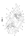
- Fig. 1 is an overall view of a power
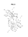
train support apparatus 3 in combination with a vehicularbody support member 6, according to an embodiment of the present invention. - Fig. 2 is an enlarged view of a
first support bracket 4. - Fig. 3 is an enlarged view of a
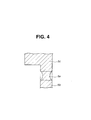
second support bracket 5. - Fig. 4 is a cross section of a
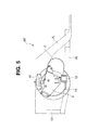
breakable portion 5e, taken along lines IV-IV in Fig. 3. - Fig. 5 is a side view of the power train support apparatus, according to the embodiment of the present invention.
- Fig. 6 shows an operation of the power train support apparatus in substantially a head-on collision of a vehicle.
- In the following, an embodiment of the present invention will be described in detail with reference to the accompanying drawings.
- For ease of understanding, the following description will contain various directional terms, such as, left, right, upper, lower, forward, rearward, and the like. However, such terms are to be understood with respect to only a drawing or drawings on which the corresponding part of element is illustrated.
- As is seen in Fig. Fig. 1, there is provided a power train support apparatus which is applied to a front engine and front wheel drive vehicle, according to an embodiment of the present invention.
- There is provided an engine 1 as a driving source of revolution. There is provided a
transaxle 2 which is a transmission unitedly connected in line with an output side of engine 1. Engine 1 (located sidewise) andtransaxle 2 constitute apower train 3. Afirst support bracket 4 is mounted on engine side ofpower train 3, while asecond support bracket 5 is mounted on transaxle side ofpower train 3. Each offirst support bracket 4 andsecond support bracket 5 is suspended with a vehicularbody support member 6. - As is seen in Fig. 2,
first support bracket 4 has asupport bracket body 4b, anupper connection 4c, alower connection 4d, and abreakable portion 4e which are so united as to constitutefirst support bracket 4. - For tightening
first support bracket 4 to engine side ofpower train 3 by means of a bolt and the like,support bracket body 4b is formed with a throughhole 4a.Upper connection 4c connected to afirst suspension member 9 is positioned higher thansupport bracket body 4b.Lower connection 4d connected to a lower connectingmember 11 is positioned lower thansupport bracket body 4b.Breakable portion 4e is formed lower thanupper connection 4c, and higher than a portion mounted topower train 3. -
Breakable portion 4e is breakable with a load (greater than or equal to its given value) applied downward fromupper connection 4c. -
Support bracket body 4b has a first face which is tightened, by means of a bolt and the like, to a position higher than a protrusion on a side face ofpower train 3. -
Support bracket body 4b further has amount plate 4b'.Mount plate 4b' bends substantially perpendicularly from the first face ofsupport bracket body 4b. Moreover,mount plate 4b' has a face contacting a rear face ofpower train 3. With this,mount plate 4b' is tightened, by means of a bolt and the like, topower train 3. - As is seen in Fig. 2, for fixing a connecting
shaft 9b offirst suspension member 9,upper connection 4c is formed with athrough hole 4f -- to be described afterward.Upper connection 4c is shaped substantially into a tongue. - As is seen in Fig. 2, for fixing a connecting
shaft 11c of lower connectingmember 11,lower connection 4d is formed with athrough hole 4g -- to be described afterward.
Breakable portion 4e is a cutout which is formed in the following manner: - Cutting partly an outer periphery of a lower area of
upper connection 4c such that the thus cut area can be smaller in cross-section than the other area. -
Breakable portion 4e is so designed as to be broken with the downward load (for example, about 25 kN) applied tobreakable portion 4e. - As is seen in Fig. 3,
second support bracket 5 has asupport bracket body 5b, anupper connection 5c, alower connection 5d, and abreakable portion 5e which are so united as to constitutesecond support bracket 5. - For tightening
second support bracket 5 to a side face of transaxle side ofpower train 3 by means of bolts and the like,support bracket body 5b is formed with a plurality of through-holes 5a.Support bracket body 5b is shaped substantially into a plate.Upper connection 5c connected tosecond suspension member 10 is positioned higher thansupport bracket body 5b.Upper connection 5c is disposed substantially in the horizontal center abovesupport bracket body 5b in such a manner as to protrude upward.Lower connection 5d connected to a lower connectingmember 12 is positioned lower thansupport bracket body 5b. With respect to a forward direction of the vehicle,lower connection 5d protrudes leftward.Broken portion 5e is formed lower thanupper connection 5c, and higher than a portion mounted topower train 3. In other words,broken portion 5e is formed in an area covered by an upper end ofsupport bracket body 5b. -
Breakable portion 5e is breakable with a load (greater than or equal to its given value) applied downward to supportbracket body 5b. - For fixing a connecting
shaft 10c ofsecond suspension member 10,upper connection 5c is formed with a through hole 5f -- to be described afterward.Upper connection 5c is a block which is shaped substantially into a tongue in plan view. - With respect to the forward direction of the vehicle,
lower connection 5d protrudes substantially perpendicularly relative to supportbracket body 5b. For fixing a connectingshaft 12c of lower connectingmember 12,lower connection 5d is formed with a throughhole 5g -- to be described afterward. Moreover,lower connection 5d is shaped substantially into a triangle pole. For securing a certain strength,lower connection 5d has a pair of reinforcingribs 5d' opposing each other. -
Breakable portion 5e is a cutout which is formed in the following manner: - Fig. 4 shows an enlarged view of a cross-section taken along lines IV-IV
in Fig. 3. Cutting partly an outer periphery of a lower area of
upper connection 5c. - Like
breakable portion 4e,breakable portion 5e is so designed as to be broken with the downward load (for example, about 25 kN) applied tobreakable portion 5e. - A strength connecting
first suspension member 9 toupper connection 4c is designed higher than a strength ofbreakable portion 4e disposed betweenupper connection 4c andsupport bracket body 4b. In addition, a strength connecting lower connectingmember 11 tolower connection 4d is designed higher than the strength ofbreakable portion 4e disposed betweenupper connection 4c andsupport bracket body 4b. - Likewise, a strength connecting
second suspension member 10 toupper connection 5c is designed higher than a strength ofbreakable portion 5e disposed betweenupper connection 5c andsupport bracket body 5b. In addition, a strength connecting lower connectingmember 12 tolower connection 5d is designed higher than the strength ofbreakable portion 5e disposed betweenupper connection 5c andsupport bracket body 5b. - As is seen in Fig. 1, vehicular
body support member 6 is constituted of: a pair of a frontright member 7R and a frontleft member 7L, asub-frame 8,first suspension member 9,second suspension member 10, lower connectingmember 11, and lower connectingmember 12. - Each of front
right member 7R and frontleft member 7L is a main skeleton member extending in a fore-and-aft direction of the vehicular body. -
Sub-frame 8 is disposed lower than frontright member 7R and frontleft member 7L. Moreover,sub-frame 8 is a sub-skeleton member which bends downward with a load (greater than or equal to its given value) applied in the fore-and-aft direction of the vehicular body.Sub-frame 8 is shaped substantially into a girder in plan view. -
First suspension member 9 is fixed to frontright member 7R in such a manner as to suspend an upper side offirst support bracket 4. -
Second suspension member 10 is fixed to frontleft member 7L in such a manner as to suspend an upper side ofsecond support bracket 5. - Lower connecting
member 11 is fixed tosub-frame 8, and connects to a lower side offirst support bracket 4. - Lower connecting
member 12 is fixed tosub-frame 8, and connects to a lower side ofsecond support bracket 5. -
Sub-frame 8 is constituted of aright sub-frame 8R and aleft sub-frame 8L. More specifically, each ofright sub-frame 8R and leftsub-frame 8L has a front end which mates with a front end of one of respective frontright member 7R and frontleft member 7L. Each ofright sub-frame 8R and leftsub-frame 8L is deflected inward in a rearward direction of the vehicular body, relative to one of respective frontright member 7R and frontleft member 7L. - Moreover,
sub-frame 8 is constituted of a front sub-frame 8Fr and a rear sub-frame 8Re. More specifically, front sub-frame 8Fr connects the front end ofright sub-frame 8R to the front end ofleft sub-frame 8L, while rear sub-frame 8Re connects a rear end ofright sub-frame 8R to a rear end ofleft sub-frame 8L. - As is seen in Fig. 5,
left sub-frame 8L (likewise,right sub-frame 8R) has the front end inclined upward from substantially a center thereof. The front end ofleft sub-frame 8L connects to the front end of frontleft member 7L by way of a connectingmember 13. - On the other hand, the rear end of each of
right sub-frame 8R and leftsub-frame 8L connects to a cross-member (not shown). - In substantially the center and on an upper face forming the upward inclination described above, each of
right sub-frame 8R and leftsub-frame 8L is formed with acutout 14. With the load (greater than or equal to its given value) applied in the fore-and-aft direction of the vehicular body,cutout 14 may encourage each ofright sub-frame 8R and leftsub-frame 8L to bend downward. -
First support member 6A is constituted of frontright member 7R,right sub-frame 8R,first suspension member 9, and lower connectingmember 11. On the other hand,second support member 6B is constituted of frontleft member 7L,left sub-frame 8L,second suspension member 10, and lower connectingmember 12. - As is seen in Fig. 1 and Fig. 2,
first suspension member 9 is constituted of asupport member body 9a and connectingshaft 9b.Support member body 9a shaped substantially into a mountain is tightened to an upper face of frontright member 7R by means of a bolt and the like. For fixation, connectingshaft 9b is inserted into throughhole 4f ofupper connection 4c offirst support bracket 4. - By means of the bolt and the like, lower connecting
member 11 is tightened rearward relative to cutout 14 on an upper face ofright sub-frame 8R. - As is seen in Fig. 2, lower connecting
member 11 is constituted of asupport plate 11a, arod 11b (connecting lever), and connectingshaft 11c. -
Support plate 11a for supportingrod 11b has a pair of plates which are opposed to each other in such a manner that supportplate 11a forms substantially a Japanese katakana character "" or a rectangular English alphabet "U". For fixing
rod 11b to supportplate 11a by means of a pin and the like, a lower end ofrod 11b is formed with a through-hole 11d. Inserting connectingshaft 11c into through-hole 4g oflower connection 4d offirst support bracket 4 can fix an upper end ofrod 11b. - As is seen in Fig. 3,
second suspension member 10 is constituted of asupport plate 10a, asupport block 10b, and connectingshaft 10c. -
Support plate 10a abuts on an inside face of frontleft member 7L. For fixingsecond suspension member 10 to frontleft member 7L by means of the bolts and the like,support plate 10a is formed with a plurality of through-holes 10d.Support block 10b is united withsupport plate 10a. For fixation, connectingshaft 10c is inserted intosupport block 10b and through hole 5f ofupper connection 5c ofsecond support bracket 5. - Lower connecting
member 12 is constituted of aninsulator 12a, amount portion 12b, and connectingshaft 12c. -
Insulator 12a shaped substantially into a circular column incorporates an elastic body for reducing vibration transmitted frompower train 3 to leftsub-frame 8L.Mount potion 12b is disposed on a side face ofinsulator 12a. Moreover, for fixing lower connectingmember 12 to leftsub-frame 8L by means of the bolt and the like rearward relative to cutout 14 on the upper face ofleft sub-frame 8L,mount portion 12b is formed with a through-hole 12d. Inserting connectingshaft 12c intoinsulator 12a and throughhole 5g oflower connection 5d ofsecond support bracket 5 can fix lower connectingmember 12 tosecond support bracket 5. - Hereinafter described referring to Fig. 6 is operation of the power train support apparatus in substantially a head-on collision of the vehicle, according to the embodiment of the present invention.
- Specifically described hereinafter is in terms of the operation on transaxle side of
power train 3. Substantially the same is applicable to engine 1 side ofpower train support 3. Therefore, repeated description is to be omitted. - An excessive load caused to substantially a head of the vehicle and applied rearward may be divided into two, namely, one is applied to front
left member 7L and the other is applied toleft sub-frame 8L. - Front left
member 7L is smashed axially (horizontally in Fig. 6). On the other hand, leftsub-frame 8L having the front end inclined upward from substantially the center thereof and formed withcutout 14 on substantially the center thereof (Fig. 5) may bend downward to a great extent in such a manner that cutout 14 (apex) is displaced downward. - Hereinabove, lower connecting
member 12 connected to leftsub-frame 8L starts the downward displacement in accordance with theleft sub-frame 8L bending downward, thereby causing a great downward load (tension) tosecond support bracket 5 which is supported withsecond suspension member 10 from upper portion. - Thereafter, left
sub-frame 8L further bends downward. When the downward load (tension) concentrated onbreakable portion 5e reaches its given value (for example, 25 kN),breakable portion 5e may be broken, to thereby releasesupport bracket body 5b fromupper connection 5c connected tosecond suspension member 10. - As a result,
second support bracket 5 and power train 3 (connected to second support bracket 5) can be dropped smoothly in accordance with the downward displacement ofleft sub-frame 8L, then, moved rearward in such a manner as to dive under a floor of the vehicular body. - In sum, assuredly dropping
power train 3 when the excessive load is applied to the head of the vehicle can bring about the following points: - Point 1: For an engine room, securing a space sufficient to absorb the collision.
- Point 2: Preventing in-vehicle space (seat occupant's space) from being
oppressed due to rearward movement of high-
rigidity power train 3. -
- The point 1 and the
point 2 can protect legs of a front seat occupant. - The breakage mechanism for dropping
power train 3 disposed onfirst support bracket 4 and second support bracket 5 (instead offirst suspension member 9 and second suspension member 10) as described above can greatly contribute to deregulation of the following: - 1. Configuration of
first suspension member 9 andsecond suspension member 10. - 2. Method of disposing
first suspension member 9 andsecond suspension member 10. - 3. Configuration of lower connecting
member 11 and lower connectingmember 12. - 4. Method of disposing lower connecting
member 11 and lower connectingmember 12. -
- More specifically described as below:
- All that are required of
first suspension member 9 andsecond suspension member 10 are described as follows: - Requirement 1: Connecting respectively to front
right member 7R and frontleft member 7L. - Requirement 2: Suspending respective
first support bracket 4 andsecond support bracket 5. -
- In other words,
first suspension member 9 andsecond suspension member 10 can be free from limitation on configuration, and limitation on disposing method relative to respective frontright member 7R and frontleft member 7L. - All that are required of lower connecting
member 11 and lower connectingmember 12 are described as follows: - Requirement 3: Connecting respectively to
right sub-frame 8R and leftsub-frame 8L for fixing respectivefirst support bracket 4 andsecond support bracket 5. - Requirement 4: Assuredly transmitting the load (for breaking respective
breakable portion 4e andbreakable portion 5e) to respectivefirst support bracket 4 andsecond support bracket 5. -
- Provided that the
requirement 3 and therequirement 4 are met, any other connecting member can replace lower connectingmember 11 and lower connectingmember 12, andright sub-frame 8R and leftsub-frame 8L can be free from any limitation, resulting in greatly improved free layout in the engine room. - In sum, a suspension member and a lower connecting member which are combined with a support bracket can be selected based on the following points:
- 1. Configuration of a power train.
- 2. Weight of the power train.
- 3. Configuration of a sub-frame.
- 4. Configuration of a front side member.
- 5. Relative location between the sub-frame and the front side member.
- 6. Cost performance.
-
- With
upper connection 4c andupper connection 5c united respectively withsupport bracket body 4b andsupport bracket body 5b, whilelower connection 4d andlower connection 5d united respectively withsupport bracket body 4b andsupport bracket body 5b, respectivefirst support bracket 4 andsecond support bracket 5 can be mounted onpower train 3 with ease. - The power train support apparatus according to the embodiment of the present invention has the following construction:
- 1.
Power train 3 is supported on engine side and transaxle side. - 2. Lower connecting
member 11 on engine side hasrod 11b. - 3. Lower connecting
member 12 on transaxle side hasinsulator 12a. -
-
Rod 11b cheaper thaninsulator 12a can contribute to preventing cost increase. - For the following cause, use of
insulator 12a for lower connectingmember 12 on transaxle side, especially when the power support apparatus is applied to the front-drive vehicle with engine 1 located sidewise, can improve vibration-proof of the members of the vehicular body: - Cause: Vibration from a wheel is directly transmitted to transaxle side.
-
- The downward load can be applied with ease to
breakable portion 4e andbreakable portion 5e sincebreakable portion 4e andbreakable portion 5e are formed on the upper part of respectivefirst support bracket 4 andsecond support bracket 5. - Moreover, each of
breakable portion 4e andbreakable portion 5e is the cutout formed in the following manner: - The lower area of one of respective
upper connection 4c andupper connection 5c is partly cut. - The above construction of the cutout can evenly break each of
breakable portion 4e andbreakable portion 5e in the following states: - 1. In a given position.
- 2. With the load greater than or equal to its given value applied.
-
- In other words, the above construction of the cutout can prevent an unexpected breakage which may be caused by comparatively a light load attributable to the vehicular body riding on a curbstone and the like.
- According to the embodiment of the present invention described above, the power train support apparatus has the following construction and operation:
- 1.
Power train 3 is fitted withfirst support bracket 4 havingbreakable portion 4e andsecond support bracket 5 havingbreakable portion 5e. - 2.
First support bracket 4 is suspended withfirst suspension member 9 fixed to frontright member 7R, whilesecond support bracket 5 is suspended withsecond suspension member 10 fixed to frontleft member 7L. - 3.
First support bracket 4 is supported with lower connectingmember 11 fixed toright sub-frame 8R, whilesecond support bracket 5 is supported with lower connectingmember 12 fixed to leftsub-frame 8L. - 4. Bending downward
right sub-frame 8R (i.e., pulling downright sub-frame 8R by way of lower connectingmember 11 fixed toright sub-frame 8R) breaksbreakable portion 4e; while bending downward leftsub-frame 8L (i.e., pulling downleft sub-frame 8L by way of lower connectingmember 12 fixed to leftsub-frame 8L) breaksbreakable portion 5e. -
- With the above construction and operation of the power train support apparatus,
power train 3 can be assuredly dropped when the excessive load is applied rearward to the head of the vehicle. - Moreover, the above construction and operation of the power train support apparatus can deregulate the limitation on the configuration and the disposing method of
first suspension member 9,second suspension member 10, lower connectingmember 11, and lower connectingmember 12. - Although the present invention has been described above by reference to a certain embodiment, the present invention is not limited to the embodiment described above. Modifications and variations of the embodiment described above will occur to those skilled in the art, in light of the above teachings.
- More specifically described as below:
- The power train support apparatus according to the embodiment is applied to the front engine and front wheel drive vehicle (FF). The present invention is, however, not limited to the above. The power train support apparatus under the present invention is applicable to other vehicles including a front engine and rear wheel drive vehicle (FR), a rear engine and rear wheel drive vehicle (RR). Moreover, the power train support apparatus under the present invention is applicable to an electric vehicle with an electric motor as a driving source of revolution.
- In addition, according to the embodiment of the present invention,
breakable portion support bracket body upper connection support bracket body upper connection breakable portion support bracket body upper connection breakable portion - In addition, according to the embodiment of the present invention,
power train 3 is supported at two portions, namely, on transaxle side and engine side. The present invention is, however, not limited to the above. Supportingpower train 3 at the center, or at three portions or more is allowed. What is of importance is to assuredly movepower train 3 downward whensub-frame 8 is bent downward attributable to the substantially head-on collision of the vehicle. In sum, the number of portions for supportingpower train 3 is arbitrary. - In addition, according to the embodiment of the present invention,
rod 11b is used for lower connectingmember 11 on engine side for preventing the cost increase. The present invention is, however, not limited to the above. Improving vibration-proof ofpower train 3 preferably uses an insulator for lower connectingmember 11 on engine side, and more preferably, forfirst suspension member 9 andsecond suspension member 10. - In addition, according to the embodiment of the present invention,
lower connection 4d andlower connection 5d of respectivefirst support bracket 4 andsecond support bracket 5 are connected to respective lower connectingmember 11 and lower connectingmember 12. The present invention is, however, not limited to the above. Withlower connection 4d andlower connection 5d omitted, the following construction is allowed: - Using a lower connecting member (such as an engine mount fixed to
right sub-frame 8R and leftsub-frame 8L) directly supportingpower train 3, so as to apply the downward load to respectivefirst support bracket 4 andsecond support bracket 5 by way ofpower train 3 when respectiveright sub-frame 8R and leftsub-frame 8L bend downward. - This application is based on a prior Japanese Patent Application No. P2002-135810 (filed on May 10, 2002 in Japan). The entire contents of the Japanese Patent Application No. P2002-135810 from which priority is claimed is incorporated herein by reference, in order to take some protection against mis-translation or omitted portions.
- The scope of the present invention is defined with reference to the following claims.
Claims (20)
- A power train support apparatus for supporting a power train (3: 1, 2) which is adapted to be dropped with a load greater than or equal to a given value thereof applied substantially in a fore-and-aft direction of a vehicular body, the power train support apparatus comprising:a support bracket (4, 5) mounted to the power train (3: 1, 2), the support bracket (4, 5) comprising an upper connection (4c, 5c) at least which is suspended with a support member (6: 6A, 6B) of the vehicular body, the support bracket (4, 5) being formed with a breakable portion (4e, 5e) which is breakable with a load greater than or equal to a given value thereof applied substantially downward from the upper connection (4c, 5c).
- The power train support apparatus as claimed in claim 1, wherein the support member (6: 6A, 6B) of the vehicular body comprises;i) a main skeleton member (7R, 7L) extending substantially in the fore-and-aft direction of the vehicular body;ii) a sub-skeleton member (8: 8R, 8L) disposed below the main skeleton member (7R, 7L), with the load greater than or equal to the given value thereof applied substantially in the fore-and-aft direction of the vehicular body, the sub-skeleton member (8: 8R, 8L) being so bent downward as to pull the power train (3: 1, 2) downward; andiii) a suspension member (9, 10) fixed to the main skeleton member (7R, 7L), the suspension member (9, 10) suspending the upper connection (4c, 5c) of the support bracket (4, 5).
- The power train support apparatus as claimed in claim 1, wherein the support member (6: 6A, 6B) of the vehicular body comprises;i) a main skeleton member (7R, 7L) extending substantially in the fore-and-aft direction of the vehicular body;ii) a sub-skeleton member (8: 8R, 8L) disposed below the main skeleton member (7R, 7L), with the load greater than or equal to the given value thereof applied substantially in the fore-and-aft direction of the vehicular body, the sub-skeleton member (8: 8R, 8L) being bent downward;iii) a suspension member (9, 10) fixed to the main skeleton member (7R, 7L), the suspension member (9, 10) suspending the upper connection (4c, 5c) of the support bracket (4, 5); andiv) a lower connecting member (11, 12) fixed to the sub-skeleton member (8: 8R, 8L), the lower connecting member (11, 12) being connected to a lower connection (4d, 5d) of the support bracket (4, 5).
- The power train support apparatus as claimed in claim 1, whereinA) the support bracket (4, 5) comprises;i) a first support bracket (4) disposed on a driving source (1) side of the power train (3: 1, 2), the driving source (1) being a source for revolution, the first support bracket (4) being formed with the breakable portion (4e); andii) a second support bracket (5) disposed on a transmission (2) side of the power train (3: 1, 2), the second support bracket (5) being formed with the breakable portion (5e),B) the support member (6: 6A, 6B) of the vehicular body comprises a first support member (6A) and a second support member (6B) each of which comprises;i) a main skeleton member (7R, 7L) extending substantially in the fore-and-aft direction of the vehicular body;ii) a sub-skeleton member (8: 8R, 8L) disposed below the main skeleton member (7R, 7L), with the load greater than or equal to the given value thereof applied substantially in the fore-and-aft direction of the vehicular body, the sub-skeleton member (8: 8R, 8L) being bent downward;iii) a suspension member (9, 10) fixed to the main skeleton member (7R, 7L), the suspension member (9, 10) suspending the upper connection (4c, 5c) of one of the first support bracket (4) and the second support bracket (5); andiv) a lower connecting member (11, 12) fixed to the sub-skeleton member (8: 8R, 8L), the lower connecting member (11, 12) being connected to a lower connection (4d, 5d) of the one of the first support bracket (4) and the second support bracket (5).
- The power train support apparatus as claimed in any of claim 1 to claim 4, wherein
the breakable portion (4e, 5e) is formed lower than the upper connection (4c), and higher than a portion mounted to the power train (3: 1, 2). - The power train support apparatus as claimed in any of claim 1 to claim 5, wherein
the breakable portion (4e, 5e) is a cutout which is formed lower than the upper connection (4c, 5c). - The power train support apparatus as claimed in any of claim 4 to claim 6, wherein
the lower connecting member (11, 12) of at least one of the first support member (6A) and the second support member (6B) includes an insulator (12a). - The power train support apparatus as claimed in any of claim 4 to claim 6, wherein
the lower connecting member (11, 12) of one of the first support member (6A) and the second support member (6B) includes an insulator (12a), and
the lower connecting member (11, 12) of the other of the first support member (6A) and the second support member (6B) includes a connecting lever (11b). - The power train support apparatus as claimed in any of claim 4 to claim 6, wherein
the lower connecting member (12) of the second support member (6B) includes an insulator (12a). - The power train support apparatus as claimed in claim 4, wherein
a strength connecting the suspension member (9, 10) to the upper connection (4c, 5c) is designed higher than a strength of the breakable portion (4e, 5e) disposed between the upper connection (4c, 5c) and a support bracket body (4b, 5b), and
a strength connecting the lower connecting member (11, 12) to the lower connection (4d, 5d) is designed higher than the strength of the breakable portion (4e, 5e). - The power train support apparatus as claimed in claim 4, wherein
the main skeleton member (7R, 7L) comprises a first main skeleton member (7R) and a second main skeleton member (7L),
the sub-skeleton member (8) comprises a first sub-skeleton member (8R) and a second sub-skeleton member (8L),
each of the first sub-skeleton member (8R) and the second sub-skeleton member (8L) has a front end which mates with a front end of one of the first main skeleton member (7R) and the second main skeleton member (7L) respectively, and
each of the first sub-skeleton member (8R) and the second sub-skeleton member (8L) is deflected inward in a rearward direction of the vehicular body, relative to one of the first main skeleton member (7R) and the second main skeleton member (7L) respectively. - The power train support apparatus as claimed in claim 11, wherein
the sub-skeleton member (8) further comprises;the front sub-skeleton member (8Fr) connecting the front end of the first sub-skeleton member (8R) to the front end of the second sub-skeleton member (8L), while the rear sub-skeleton member (8Re) connecting a rear end of the first sub-skeleton member (8R) to a rear end of the second sub-skeleton member (8L).i) a front sub-skeleton member (8Fr), andii) a rear sub-skeleton member (8Re), - The power train support apparatus as claimed in claim 12, wherein
each of the first sub-skeleton member (8R) and the second sub-skeleton member (8L) has the front end inclined upward from substantially a center thereof, the front end of each of the first sub-skeleton member (8R) and the second sub-skeleton member (8L) connecting, by way of a connecting member 13, to the front end of one of the first main skeleton member (7R) and the second main skeleton member (7L) respectively. - The power train support apparatus as claimed in claim 13, wherein
in substantially a center and on an upper face forming the upward inclination, each of the first sub-skeleton member (8R) and the second sub-skeleton member (8L) is formed with a cutout (14), and
with the load greater than or equal to the given value thereof applied in the fore-and-aft direction of the vehicular body, the cutout (14) encourages each of the first sub-skeleton member (8R) and the second sub-skeleton member (8L) to bend downward. - The power train support apparatus as claimed in claim 1, wherein
the breakable portion (4e, 5e) has a reduced thickness partly between a support bracket body (4b, 5b) and the upper connection (4c, 5c). - The power train support apparatus as claimed in claim 1, wherein
the breakable portion (4e, 5e) is formed with a plurality of through-holes along the breakable portion (4e, 5e). - The power train support apparatus as claimed in claim 4, wherein the power train (3) is supported at the driving source (1) side which is an engine (1) side and the transmission (2) side which is a transaxle (2) side.
- The power train support apparatus as claimed in claim 4, wherein the power train (3) is supported at a center thereof.
- The power train support apparatus as claimed in claim 4, wherein the power train (3) is supported at three portions or more.
- The power train support apparatus as claimed in claim 2, wherein the suspension member (9, 10) includes an insulator (12a).
Applications Claiming Priority (2)
| Application Number | Priority Date | Filing Date | Title |
|---|---|---|---|
| JP2002135810A JP4023208B2 (en) | 2002-05-10 | 2002-05-10 | Powertrain support device |
| JP2002135810 | 2002-05-10 |
Publications (3)
| Publication Number | Publication Date |
|---|---|
| EP1361099A2 true EP1361099A2 (en) | 2003-11-12 |
| EP1361099A3 EP1361099A3 (en) | 2004-11-17 |
| EP1361099B1 EP1361099B1 (en) | 2008-05-28 |
Family
ID=29244232
Family Applications (1)
| Application Number | Title | Priority Date | Filing Date |
|---|---|---|---|
| EP03251895A Expired - Lifetime EP1361099B1 (en) | 2002-05-10 | 2003-03-26 | Power train support apparatus |
Country Status (4)
| Country | Link |
|---|---|
| US (1) | US7040446B2 (en) |
| EP (1) | EP1361099B1 (en) |
| JP (1) | JP4023208B2 (en) |
| DE (1) | DE60321264D1 (en) |
Cited By (9)
| Publication number | Priority date | Publication date | Assignee | Title |
|---|---|---|---|---|
| DE10354639A1 (en) * | 2003-11-22 | 2005-08-04 | Bayerische Motoren Werke Ag | Aggregate fastening mechanism for motor vehicle, has drive unit lowered opposite to body and carriage under front hood, and control device connected parallel to vertical axis of vehicle, where buffer zone is provided for hood deformation |
| EP2476603A3 (en) * | 2011-01-14 | 2013-05-15 | Aston Martin Lagonda Limited | Components for motor vehicle crash structure |
| FR3001942A1 (en) * | 2013-02-14 | 2014-08-15 | Peugeot Citroen Automobiles Sa | Power unit cradle and body front longeron assembly for motor vehicle, has arm with upper end fixed at front longeron by screw ensuring mechanical connection between longeron and arm, where connection is supplemented by link |
| ITTO20130474A1 (en) * | 2013-06-07 | 2014-12-08 | Fiat Group Automobiles Spa | MOTOR VEHICLE EQUIPPED WITH A RELEASE SYSTEM TO DETACH A CROSS IN THE ENGINE COMPARTMENT IN CASE OF FRONTAL IMPACT |
| EP3181390A1 (en) * | 2015-12-17 | 2017-06-21 | Audi Ag | Assembly mount for a vehicle actuator |
| WO2020126599A1 (en) * | 2018-12-20 | 2020-06-25 | Renault S.A.S | Motor vehicle comprising an engine support and a chassis |
| GB2587624A (en) * | 2019-10-01 | 2021-04-07 | Caterpillar Inc | Mounting system |
| EP3808635A1 (en) | 2019-10-17 | 2021-04-21 | FCA Italy S.p.A. | Motor vehicle provided with a release system for uncoupling a cross member in the engine compartment in case of a front crash |
| RU2793160C2 (en) * | 2018-12-20 | 2023-03-29 | Рено С.А.С | Motor vehicle with engine support and frame |
Families Citing this family (37)
| Publication number | Priority date | Publication date | Assignee | Title |
|---|---|---|---|---|
| JP3900048B2 (en) * | 2001-11-19 | 2007-04-04 | 日産自動車株式会社 | Body front structure |
| DE10328170A1 (en) * | 2003-06-24 | 2005-01-13 | Daimlerchrysler Ag | Safety engine cover for road vehicle deforms if vehicle hits pedestrian, with given clearance between top of engine and underside of engine cover and engine may be driven downward on flexible mounting |
| JP4231473B2 (en) * | 2004-10-19 | 2009-02-25 | 本田技研工業株式会社 | Steering gear box mounting structure |
| FR2884181B1 (en) * | 2005-04-11 | 2007-06-15 | Renault Sas | ENGINE ASSEMBLY OF A VEHICLE |
| WO2007037113A1 (en) * | 2005-09-27 | 2007-04-05 | Autoliv Development Ab | Impact reducing structure of vehicle |
| US20070221430A1 (en) * | 2006-03-21 | 2007-09-27 | Allison Kenneth M Sr | Modular automobile system and method |
| JP4832171B2 (en) * | 2006-06-06 | 2011-12-07 | 富士重工業株式会社 | Vehicle front structure |
| DE102006041094B4 (en) * | 2006-09-01 | 2015-04-02 | Audi Ag | Bearing device for mounting a vehicle component on a body of a vehicle |
| KR20080042389A (en) * | 2006-11-09 | 2008-05-15 | 현대자동차주식회사 | Stopper for hydraulic engine mount of vehicle |
| EP1977956B1 (en) * | 2007-04-03 | 2012-08-29 | Nissan Motor Co., Ltd. | Installation structure and method of vehicular suspension |
| JP4956794B2 (en) * | 2007-04-03 | 2012-06-20 | 日産自動車株式会社 | Suspension mounting structure |
| JP5136229B2 (en) * | 2008-06-09 | 2013-02-06 | 日産自動車株式会社 | Powertrain support structure |
| US7762619B2 (en) * | 2008-07-29 | 2010-07-27 | Ford Global Technologies, Llc | Sequential crash hinges in automotive frame rails |
| JP4585585B2 (en) * | 2008-08-06 | 2010-11-24 | 本田技研工業株式会社 | Body structure |
| US8132640B2 (en) * | 2008-08-07 | 2012-03-13 | Honda Motor Co., Ltd. | Frangible mount for a vehicle differential |
| US7975787B2 (en) * | 2008-11-06 | 2011-07-12 | Clark Equipment Company | Low mount three point engine and pump mounting |
| US8215444B2 (en) * | 2009-07-09 | 2012-07-10 | Ford Global Technologies | Roll restrictor system for an automotive powertrain |
| DE102009034905A1 (en) * | 2009-07-28 | 2011-02-03 | GM Global Technology Operations, Inc., Detroit | Automobile front end and method for producing a motor vehicle front part |
| KR101244708B1 (en) | 2010-10-07 | 2013-03-18 | 기아자동차주식회사 | Transmission mount type of side assembling |
| TWI435813B (en) * | 2011-06-28 | 2014-05-01 | Metal Ind Res & Dev Ct | Electric vehicle power module fixed bracket |
| JP5929435B2 (en) * | 2012-04-04 | 2016-06-08 | スズキ株式会社 | Hybrid vehicle power unit |
| EP3023281B1 (en) * | 2013-07-18 | 2017-04-05 | Nissan Motor Co., Ltd. | Hybrid vehicle |
| JP5696955B2 (en) * | 2013-07-30 | 2015-04-08 | 三菱自動車工業株式会社 | Rotating electric machine for vehicles |
| US9158868B2 (en) * | 2013-08-22 | 2015-10-13 | GM Global Technology Operations LLC | Vehicle powertrain mounting system and method of designing same |
| JP6151237B2 (en) * | 2014-11-17 | 2017-06-21 | 本田技研工業株式会社 | Subframe structure |
| JP6518168B2 (en) * | 2015-08-26 | 2019-05-22 | 本田技研工業株式会社 | Motor mounting structure |
| JP6529888B2 (en) * | 2015-10-22 | 2019-06-12 | 本田技研工業株式会社 | Fuel cell stack mounting structure |
| US9738148B1 (en) * | 2016-02-17 | 2017-08-22 | GM Global Technology Operations LLC | Stud assembly |
| JP6658500B2 (en) * | 2016-12-26 | 2020-03-04 | トヨタ自動車株式会社 | Fuel cell mounting structure |
| KR102258481B1 (en) * | 2017-03-27 | 2021-06-01 | 현대자동차주식회사 | Structure of Engine Mount |
| US10059380B1 (en) * | 2017-08-08 | 2018-08-28 | Ford Global Technologies, Llc | Mounting an accessory to a frame member |
| GB2569582B (en) | 2017-12-20 | 2020-06-17 | Ford Global Tech Llc | A powertrain support mount assembly |
| JP2019188884A (en) * | 2018-04-19 | 2019-10-31 | トヨタ自動車株式会社 | Fuel cell vehicle |
| CN112009568B (en) * | 2019-05-30 | 2022-10-28 | 马自达汽车株式会社 | Powertrain support structure of vehicle |
| JP7281102B2 (en) * | 2019-05-30 | 2023-05-25 | マツダ株式会社 | VEHICLE POWERTRAIN SUPPORT METHOD AND SUPPORT STRUCTURE |
| JP7259667B2 (en) * | 2019-09-17 | 2023-04-18 | トヨタ自動車株式会社 | Vehicle mounting structure and vehicle mounting method for fuel cell stack |
| KR20220090986A (en) * | 2020-12-23 | 2022-06-30 | 현대자동차주식회사 | Fuel cell vehicle |
Citations (3)
| Publication number | Priority date | Publication date | Assignee | Title |
|---|---|---|---|---|
| JPH07164894A (en) | 1993-12-14 | 1995-06-27 | Suzuki Motor Corp | Engine support structure |
| US6131685A (en) | 1995-12-27 | 2000-10-17 | Toyota Jidosha Kabushiki Kaisha | Power train supporting apparatus |
| JP2002135810A (en) | 2000-10-24 | 2002-05-10 | Institute For Welcome System Ltd | Mechanism and method for smoothly performing efficient television program viewing, audience rating research and electronic commerce by integrating communication terminal for moving object such as portable telephone and remote controller for television receiver and television recorder |
Family Cites Families (11)
| Publication number | Priority date | Publication date | Assignee | Title |
|---|---|---|---|---|
| DE2056102A1 (en) * | 1970-11-14 | 1972-05-18 | Volkswagenwerk Ag, 3180 Wolfsburg | Arrangement of a drive unit in the front end of a motor vehicle |
| FR2120386A5 (en) * | 1970-12-31 | 1972-08-18 | Peugeot & Renault | |
| DE3117378C2 (en) * | 1981-05-02 | 1986-10-23 | Dr.Ing.H.C. F. Porsche Ag, 7000 Stuttgart | Suspension for a drive unit of a motor vehicle which is arranged at the front, in particular transversely |
| DE3224935C2 (en) * | 1982-07-03 | 1984-04-19 | Adam Opel AG, 6090 Rüsselsheim | Drive unit for motor vehicles |
| DE4326396C2 (en) * | 1993-08-06 | 2001-07-26 | Daimler Chrysler Ag | Motor vehicle with a drive motor inclined at an acute angle to the horizontal |
| JP3417811B2 (en) * | 1997-09-26 | 2003-06-16 | ダイハツ工業株式会社 | Power plant mounting structure |
| GB2329877A (en) * | 1997-10-01 | 1999-04-07 | Rover Group | Vehicle subframe attached to a structure by non-frangible and frangible mountings |
| JP2002002310A (en) * | 2000-06-15 | 2002-01-09 | Mitsubishi Motors Corp | Power plant support structure |
| JP2002012040A (en) * | 2000-06-29 | 2002-01-15 | Mitsubishi Motors Corp | Power plant support structure |
| JP4054172B2 (en) * | 2000-10-23 | 2008-02-27 | 株式会社神戸製鋼所 | Engine mount |
| JP3575439B2 (en) * | 2001-06-04 | 2004-10-13 | 日産自動車株式会社 | Automotive power unit layout |
-
2002
- 2002-05-10 JP JP2002135810A patent/JP4023208B2/en not_active Expired - Lifetime
-
2003
- 2003-03-26 EP EP03251895A patent/EP1361099B1/en not_active Expired - Lifetime
- 2003-03-26 DE DE60321264T patent/DE60321264D1/en not_active Expired - Lifetime
- 2003-04-03 US US10/405,629 patent/US7040446B2/en not_active Expired - Lifetime
Patent Citations (3)
| Publication number | Priority date | Publication date | Assignee | Title |
|---|---|---|---|---|
| JPH07164894A (en) | 1993-12-14 | 1995-06-27 | Suzuki Motor Corp | Engine support structure |
| US6131685A (en) | 1995-12-27 | 2000-10-17 | Toyota Jidosha Kabushiki Kaisha | Power train supporting apparatus |
| JP2002135810A (en) | 2000-10-24 | 2002-05-10 | Institute For Welcome System Ltd | Mechanism and method for smoothly performing efficient television program viewing, audience rating research and electronic commerce by integrating communication terminal for moving object such as portable telephone and remote controller for television receiver and television recorder |
Cited By (14)
| Publication number | Priority date | Publication date | Assignee | Title |
|---|---|---|---|---|
| DE10354639A1 (en) * | 2003-11-22 | 2005-08-04 | Bayerische Motoren Werke Ag | Aggregate fastening mechanism for motor vehicle, has drive unit lowered opposite to body and carriage under front hood, and control device connected parallel to vertical axis of vehicle, where buffer zone is provided for hood deformation |
| US9039070B2 (en) | 2011-01-14 | 2015-05-26 | Aston Martin Lagonda Limited | Crash load absorption structures for motor vehicles |
| EP2476603A3 (en) * | 2011-01-14 | 2013-05-15 | Aston Martin Lagonda Limited | Components for motor vehicle crash structure |
| FR3001942A1 (en) * | 2013-02-14 | 2014-08-15 | Peugeot Citroen Automobiles Sa | Power unit cradle and body front longeron assembly for motor vehicle, has arm with upper end fixed at front longeron by screw ensuring mechanical connection between longeron and arm, where connection is supplemented by link |
| US9150251B2 (en) | 2013-06-07 | 2015-10-06 | Fiat Group Automobiles S.P.A. | Motor vehicle provided with a release system to uncouple a cross member in the engine compartment in the event of a front crash |
| EP2810854A1 (en) | 2013-06-07 | 2014-12-10 | Fiat Group Automobiles S.p.A. | Motor vehicle provided with a release system to uncouple a cross member in the engine compartment in the event of a front crash |
| ITTO20130474A1 (en) * | 2013-06-07 | 2014-12-08 | Fiat Group Automobiles Spa | MOTOR VEHICLE EQUIPPED WITH A RELEASE SYSTEM TO DETACH A CROSS IN THE ENGINE COMPARTMENT IN CASE OF FRONTAL IMPACT |
| EP3181390A1 (en) * | 2015-12-17 | 2017-06-21 | Audi Ag | Assembly mount for a vehicle actuator |
| US10118476B2 (en) | 2015-12-17 | 2018-11-06 | Audi Ag | Engine mount assembly for a vehicle drive unit |
| WO2020126599A1 (en) * | 2018-12-20 | 2020-06-25 | Renault S.A.S | Motor vehicle comprising an engine support and a chassis |
| FR3090552A1 (en) * | 2018-12-20 | 2020-06-26 | Renault S.A.S | Motor vehicle comprising an engine support and a chassis |
| RU2793160C2 (en) * | 2018-12-20 | 2023-03-29 | Рено С.А.С | Motor vehicle with engine support and frame |
| GB2587624A (en) * | 2019-10-01 | 2021-04-07 | Caterpillar Inc | Mounting system |
| EP3808635A1 (en) | 2019-10-17 | 2021-04-21 | FCA Italy S.p.A. | Motor vehicle provided with a release system for uncoupling a cross member in the engine compartment in case of a front crash |
Also Published As
| Publication number | Publication date |
|---|---|
| EP1361099B1 (en) | 2008-05-28 |
| US20030209380A1 (en) | 2003-11-13 |
| US7040446B2 (en) | 2006-05-09 |
| JP2003326983A (en) | 2003-11-19 |
| EP1361099A3 (en) | 2004-11-17 |
| DE60321264D1 (en) | 2008-07-10 |
| JP4023208B2 (en) | 2007-12-19 |
Similar Documents
| Publication | Publication Date | Title |
|---|---|---|
| EP1361099B1 (en) | Power train support apparatus | |
| CN106347090B (en) | Vehicle | |
| JP3351233B2 (en) | Powertrain support device | |
| EP1852331B1 (en) | Front structure of vehicle body | |
| CN110576908B (en) | Vehicle rear structure | |
| JPH08268322A (en) | Car body | |
| JP4168765B2 (en) | Bracket for engine mount | |
| JP2007137243A (en) | Supporting structure of steering system | |
| EP3546299B1 (en) | Knee-airbag-device attachment structure for a vehicle, a protection system, a vehicle, and a method of arranging a knee-airbag-device | |
| CN110316137B (en) | Mounting structure of knee airbag device for vehicle | |
| JPH10264862A (en) | Front part car body structure of automobile | |
| JP6609978B2 (en) | Wiring fixing structure of vehicle | |
| KR102567273B1 (en) | Vehicle body structure | |
| JP2006137374A (en) | Front body structure of vehicle | |
| US11541714B2 (en) | Vehicle | |
| EP1260427A2 (en) | Bracket for motor vehicle | |
| US11104383B2 (en) | Vehicle front portion structure | |
| US6419270B1 (en) | Integrated steering column and pedal mounting system | |
| JP2002002310A (en) | Power plant support structure | |
| JP3356978B2 (en) | Power unit mounting structure | |
| JP3730417B2 (en) | Support structure for differential device | |
| US20230303184A1 (en) | Vehicle front structure | |
| JP7144527B2 (en) | Front subframe structure | |
| CN211844640U (en) | Header board crossbeam support and vehicle | |
| EP1100712B1 (en) | Motor vehicle sub-assembly |
Legal Events
| Date | Code | Title | Description |
|---|---|---|---|
| PUAI | Public reference made under article 153(3) epc to a published international application that has entered the european phase |
Free format text: ORIGINAL CODE: 0009012 |
|
| 17P | Request for examination filed |
Effective date: 20030423 |
|
| AK | Designated contracting states |
Kind code of ref document: A2 Designated state(s): AT BE BG CH CY CZ DE DK EE ES FI FR GB GR HU IE IT LI LU MC NL PT RO SE SI SK TR |
|
| AX | Request for extension of the european patent |
Extension state: AL LT LV MK |
|
| PUAL | Search report despatched |
Free format text: ORIGINAL CODE: 0009013 |
|
| AK | Designated contracting states |
Kind code of ref document: A3 Designated state(s): AT BE BG CH CY CZ DE DK EE ES FI FR GB GR HU IE IT LI LU MC NL PT RO SE SI SK TR |
|
| AX | Request for extension of the european patent |
Extension state: AL LT LV MK |
|
| AKX | Designation fees paid |
Designated state(s): DE FR GB |
|
| 17Q | First examination report despatched |
Effective date: 20061005 |
|
| GRAP | Despatch of communication of intention to grant a patent |
Free format text: ORIGINAL CODE: EPIDOSNIGR1 |
|
| GRAC | Information related to communication of intention to grant a patent modified |
Free format text: ORIGINAL CODE: EPIDOSCIGR1 |
|
| GRAS | Grant fee paid |
Free format text: ORIGINAL CODE: EPIDOSNIGR3 |
|
| GRAA | (expected) grant |
Free format text: ORIGINAL CODE: 0009210 |
|
| AK | Designated contracting states |
Kind code of ref document: B1 Designated state(s): DE FR GB |
|
| REG | Reference to a national code |
Ref country code: GB Ref legal event code: FG4D |
|
| REF | Corresponds to: |
Ref document number: 60321264 Country of ref document: DE Date of ref document: 20080710 Kind code of ref document: P |
|
| PLBE | No opposition filed within time limit |
Free format text: ORIGINAL CODE: 0009261 |
|
| STAA | Information on the status of an ep patent application or granted ep patent |
Free format text: STATUS: NO OPPOSITION FILED WITHIN TIME LIMIT |
|
| 26N | No opposition filed |
Effective date: 20090303 |
|
| REG | Reference to a national code |
Ref country code: FR Ref legal event code: PLFP Year of fee payment: 14 |
|
| REG | Reference to a national code |
Ref country code: FR Ref legal event code: PLFP Year of fee payment: 15 |
|
| REG | Reference to a national code |
Ref country code: FR Ref legal event code: PLFP Year of fee payment: 16 |
|
| PGFP | Annual fee paid to national office [announced via postgrant information from national office to epo] |
Ref country code: GB Payment date: 20220203 Year of fee payment: 20 Ref country code: DE Payment date: 20220203 Year of fee payment: 20 |
|
| PGFP | Annual fee paid to national office [announced via postgrant information from national office to epo] |
Ref country code: FR Payment date: 20220209 Year of fee payment: 20 |
|
| REG | Reference to a national code |
Ref country code: DE Ref legal event code: R071 Ref document number: 60321264 Country of ref document: DE |
|
| REG | Reference to a national code |
Ref country code: GB Ref legal event code: PE20 Expiry date: 20230325 |
|
| PG25 | Lapsed in a contracting state [announced via postgrant information from national office to epo] |
Ref country code: GB Free format text: LAPSE BECAUSE OF EXPIRATION OF PROTECTION Effective date: 20230325 |