EP1358976A1 - Vorrichtung zum Herauslösen von Teilbereichen aus einem bahnartigen Folienmaterial - Google Patents
Vorrichtung zum Herauslösen von Teilbereichen aus einem bahnartigen Folienmaterial Download PDFInfo
- Publication number
- EP1358976A1 EP1358976A1 EP03010440A EP03010440A EP1358976A1 EP 1358976 A1 EP1358976 A1 EP 1358976A1 EP 03010440 A EP03010440 A EP 03010440A EP 03010440 A EP03010440 A EP 03010440A EP 1358976 A1 EP1358976 A1 EP 1358976A1
- Authority
- EP
- European Patent Office
- Prior art keywords
- film material
- edge
- cutting edge
- rotation
- material web
- Prior art date
- Legal status (The legal status is an assumption and is not a legal conclusion. Google has not performed a legal analysis and makes no representation as to the accuracy of the status listed.)
- Granted
Links
Images

Classifications
-
- B—PERFORMING OPERATIONS; TRANSPORTING
- B26—HAND CUTTING TOOLS; CUTTING; SEVERING
- B26F—PERFORATING; PUNCHING; CUTTING-OUT; STAMPING-OUT; SEVERING BY MEANS OTHER THAN CUTTING
- B26F1/00—Perforating; Punching; Cutting-out; Stamping-out; Apparatus therefor
- B26F1/38—Cutting-out; Stamping-out
- B26F1/40—Cutting-out; Stamping-out using a press, e.g. of the ram type
- B26F1/42—Cutting-out; Stamping-out using a press, e.g. of the ram type having a pressure roller
-
- B—PERFORMING OPERATIONS; TRANSPORTING
- B25—HAND TOOLS; PORTABLE POWER-DRIVEN TOOLS; MANIPULATORS
- B25B—TOOLS OR BENCH DEVICES NOT OTHERWISE PROVIDED FOR, FOR FASTENING, CONNECTING, DISENGAGING, OR HOLDING
- B25B11/00—Work holders not covered by any preceding group in the subclass, e.g. magnetic work holders, vacuum work holders
- B25B11/005—Vacuum work holders
-
- B—PERFORMING OPERATIONS; TRANSPORTING
- B25—HAND TOOLS; PORTABLE POWER-DRIVEN TOOLS; MANIPULATORS
- B25B—TOOLS OR BENCH DEVICES NOT OTHERWISE PROVIDED FOR, FOR FASTENING, CONNECTING, DISENGAGING, OR HOLDING
- B25B5/00—Clamps
- B25B5/16—Details, e.g. jaws, jaw attachments
- B25B5/163—Jaws or jaw attachments
-
- B—PERFORMING OPERATIONS; TRANSPORTING
- B26—HAND CUTTING TOOLS; CUTTING; SEVERING
- B26D—CUTTING; DETAILS COMMON TO MACHINES FOR PERFORATING, PUNCHING, CUTTING-OUT, STAMPING-OUT OR SEVERING
- B26D1/00—Cutting through work characterised by the nature or movement of the cutting member or particular materials not otherwise provided for; Apparatus or machines therefor; Cutting members therefor
- B26D1/01—Cutting through work characterised by the nature or movement of the cutting member or particular materials not otherwise provided for; Apparatus or machines therefor; Cutting members therefor involving a cutting member which does not travel with the work
- B26D1/44—Cutting through work characterised by the nature or movement of the cutting member or particular materials not otherwise provided for; Apparatus or machines therefor; Cutting members therefor involving a cutting member which does not travel with the work having a cup or like cutting member
- B26D1/445—Cutting through work characterised by the nature or movement of the cutting member or particular materials not otherwise provided for; Apparatus or machines therefor; Cutting members therefor involving a cutting member which does not travel with the work having a cup or like cutting member for thin material, e.g. for sheets, strips or the like
-
- B—PERFORMING OPERATIONS; TRANSPORTING
- B26—HAND CUTTING TOOLS; CUTTING; SEVERING
- B26D—CUTTING; DETAILS COMMON TO MACHINES FOR PERFORATING, PUNCHING, CUTTING-OUT, STAMPING-OUT OR SEVERING
- B26D7/00—Details of apparatus for cutting, cutting-out, stamping-out, punching, perforating, or severing by means other than cutting
- B26D7/01—Means for holding or positioning work
- B26D7/018—Holding the work by suction
-
- B—PERFORMING OPERATIONS; TRANSPORTING
- B26—HAND CUTTING TOOLS; CUTTING; SEVERING
- B26D—CUTTING; DETAILS COMMON TO MACHINES FOR PERFORATING, PUNCHING, CUTTING-OUT, STAMPING-OUT OR SEVERING
- B26D7/00—Details of apparatus for cutting, cutting-out, stamping-out, punching, perforating, or severing by means other than cutting
- B26D7/01—Means for holding or positioning work
- B26D7/02—Means for holding or positioning work with clamping means
-
- B—PERFORMING OPERATIONS; TRANSPORTING
- B26—HAND CUTTING TOOLS; CUTTING; SEVERING
- B26D—CUTTING; DETAILS COMMON TO MACHINES FOR PERFORATING, PUNCHING, CUTTING-OUT, STAMPING-OUT OR SEVERING
- B26D7/00—Details of apparatus for cutting, cutting-out, stamping-out, punching, perforating, or severing by means other than cutting
- B26D7/01—Means for holding or positioning work
- B26D7/02—Means for holding or positioning work with clamping means
- B26D7/025—Means for holding or positioning work with clamping means acting upon planar surfaces
-
- B—PERFORMING OPERATIONS; TRANSPORTING
- B26—HAND CUTTING TOOLS; CUTTING; SEVERING
- B26D—CUTTING; DETAILS COMMON TO MACHINES FOR PERFORATING, PUNCHING, CUTTING-OUT, STAMPING-OUT OR SEVERING
- B26D7/00—Details of apparatus for cutting, cutting-out, stamping-out, punching, perforating, or severing by means other than cutting
- B26D7/18—Means for removing cut-out material or waste
- B26D7/1818—Means for removing cut-out material or waste by pushing out
-
- B—PERFORMING OPERATIONS; TRANSPORTING
- B26—HAND CUTTING TOOLS; CUTTING; SEVERING
- B26D—CUTTING; DETAILS COMMON TO MACHINES FOR PERFORATING, PUNCHING, CUTTING-OUT, STAMPING-OUT OR SEVERING
- B26D7/00—Details of apparatus for cutting, cutting-out, stamping-out, punching, perforating, or severing by means other than cutting
- B26D7/20—Cutting beds
-
- B—PERFORMING OPERATIONS; TRANSPORTING
- B26—HAND CUTTING TOOLS; CUTTING; SEVERING
- B26F—PERFORATING; PUNCHING; CUTTING-OUT; STAMPING-OUT; SEVERING BY MEANS OTHER THAN CUTTING
- B26F1/00—Perforating; Punching; Cutting-out; Stamping-out; Apparatus therefor
- B26F1/38—Cutting-out; Stamping-out
- B26F1/3806—Cutting-out; Stamping-out wherein relative movements of tool head and work during cutting have a component tangential to the work surface
- B26F1/3813—Cutting-out; Stamping-out wherein relative movements of tool head and work during cutting have a component tangential to the work surface wherein the tool head is moved in a plane parallel to the work in a coordinate system fixed with respect to the work
- B26F1/3826—Cutting-out; Stamping-out wherein relative movements of tool head and work during cutting have a component tangential to the work surface wherein the tool head is moved in a plane parallel to the work in a coordinate system fixed with respect to the work using a rotary circular cutting member
-
- B—PERFORMING OPERATIONS; TRANSPORTING
- B26—HAND CUTTING TOOLS; CUTTING; SEVERING
- B26F—PERFORATING; PUNCHING; CUTTING-OUT; STAMPING-OUT; SEVERING BY MEANS OTHER THAN CUTTING
- B26F1/00—Perforating; Punching; Cutting-out; Stamping-out; Apparatus therefor
- B26F1/38—Cutting-out; Stamping-out
- B26F1/3846—Cutting-out; Stamping-out cutting out discs or the like
-
- B—PERFORMING OPERATIONS; TRANSPORTING
- B26—HAND CUTTING TOOLS; CUTTING; SEVERING
- B26D—CUTTING; DETAILS COMMON TO MACHINES FOR PERFORATING, PUNCHING, CUTTING-OUT, STAMPING-OUT OR SEVERING
- B26D1/00—Cutting through work characterised by the nature or movement of the cutting member or particular materials not otherwise provided for; Apparatus or machines therefor; Cutting members therefor
- B26D1/01—Cutting through work characterised by the nature or movement of the cutting member or particular materials not otherwise provided for; Apparatus or machines therefor; Cutting members therefor involving a cutting member which does not travel with the work
- B26D1/12—Cutting through work characterised by the nature or movement of the cutting member or particular materials not otherwise provided for; Apparatus or machines therefor; Cutting members therefor involving a cutting member which does not travel with the work having a cutting member moving about an axis
- B26D1/25—Cutting through work characterised by the nature or movement of the cutting member or particular materials not otherwise provided for; Apparatus or machines therefor; Cutting members therefor involving a cutting member which does not travel with the work having a cutting member moving about an axis with a non-circular cutting member
- B26D1/26—Cutting through work characterised by the nature or movement of the cutting member or particular materials not otherwise provided for; Apparatus or machines therefor; Cutting members therefor involving a cutting member which does not travel with the work having a cutting member moving about an axis with a non-circular cutting member moving about an axis substantially perpendicular to the line of cut
- B26D1/28—Cutting through work characterised by the nature or movement of the cutting member or particular materials not otherwise provided for; Apparatus or machines therefor; Cutting members therefor involving a cutting member which does not travel with the work having a cutting member moving about an axis with a non-circular cutting member moving about an axis substantially perpendicular to the line of cut and rotating continuously in one direction during cutting
- B26D1/285—Cutting through work characterised by the nature or movement of the cutting member or particular materials not otherwise provided for; Apparatus or machines therefor; Cutting members therefor involving a cutting member which does not travel with the work having a cutting member moving about an axis with a non-circular cutting member moving about an axis substantially perpendicular to the line of cut and rotating continuously in one direction during cutting for thin material, e.g. for sheets, strips or the like
Definitions
- the present invention relates to a device for Removing part of a sheet-like film material.
- the film material can be a single-layer or Be multilayer material and for example on one Roll body may be present coiled. From this reel body such a path can be drawn off and in one clocked or continuous work processes processed such as deformed. Corresponding depending on the application, it may be necessary Detach partial areas from the sheet-like film material.
- the invention is based on this prior art based on the task of being economically viable Possibility to separate partial areas from one specify sheet-like film material, in particular also in moving foil material.
- the devices according to the invention stand out accordingly from either a cutting edge in a rolling motion through the film material web is pushed through or that a cutting edge in one pulling cut pulled through the film material web becomes.
- Both devices have the advantage that the necessary compressive or tensile forces to Cutting the film material are relatively small. This has result in the corresponding devices comparatively slim and therefore easy to train can. These devices are therefore well suited while the separation process, for example, with the in the transport direction moving track to be moved.
- the cutting edge can get stuck next to the knife edge be arranged elastically compressible buffer part.
- this buffer part compresses and relaxes again when moving out this area of the cutting edge from the film material web.
- the severed sheet of film material from the cutting edge or knife edge moved away. This will prevents the severed area of the film material web Attach to the side of the knife edge can.
- the knife edge can become a self-contained ring be shaped to provide a desirable complete detachment of the respective sub-area from the film material web enable.
- This knife-cutting ring can be used for better Handling the device attached to a plate be attached. This makes it possible to have a roller from above to let it roll over the plate and thereby circumferentially through the knife edge ring To push the film material web through.
- the film material web is the collar-like edge area one with a liquid or pasty Filler filled bag.
- this border area there is one lower track, which deforms into a pot-like container and is filled with the filler, with an upper sheet that forms the lid of this pot-like container, filler-tight connected.
- Devices can then be used in a railway area separated several pot-like containers from the web become. During the separation process, the device is connected moving with the moving train.
- Embodiments are also shown in the drawing another device where the cutting edge not in a rolling motion but in a pulling motion Cut is pulled through the film material web.
- Embodiments for this include, for example, that the Knife edge perpendicular to the film material first in the Foil material is moved in and then the knife edge is brought into rotation about an axis of rotation.
- the axis of rotation is the center of a circular arc.
- Knife edge of such a device in the floor plan already be shaped like a circular arc.
- the cutting edge can a serrated edge or a serrated edge have.
- a hold-down in addition the knife edge must be present against the film material can be pressed.
- This hold-down holds the Film material web immovable during the cutting process firmly.
- Such a hold-down can also in Interior that is driven by the circular rotating Knife edge is enclosed, can be arranged.
- the knife edge is used to create a pulling cut present on a rotary cylinder. It can the knife edge or the rotary cylinder perpendicular to the film material so that they are in the film material moves in.
- the knife edge can be a razor blade.
- the longitudinal axis the razor blade is at an acute angle to the plane the sheet of film material arranged to the desired one to allow pulling cut.
- a separation station 10 shown in detail in FIG. 1 is part of a machine system by means of which a lower Film web 12 and an upper film web 14 treated in this way are that the lower track 12 to pot-like containers 16 deformed, filled with filler 18 and by means of the upper Lane 14 was closed.
- the resulting Foil material web 20 thus has separate ones Areas that represent pot-like containers 16.
- the pot-like containers 16 are defined by edge areas 22 separated from each other. In these edge areas 22 are the two tracks 12, 14 firmly connected. in the In the present case, the two lanes are water-soluble are welded to one another in the edge regions 22. In the film material web 20 becomes these edge regions 22 separated, so that the pot-like containers 16 then are individually present.
- Edge areas 22 represent a waste product.
- the transport plate 24 moves via a mechanical substructure 25.
- the transport plate 24 has the number of pot-like Containers 16 corresponding vaults 28, the size and shape of the containers 16 correspond.
- each arch 28 leads to a branch channel 30 Cross channel 32, the line with a longitudinal channel 34th connected is.
- a line 36 leads from the longitudinal channel 34 a vacuum generator 38. With the help of the vacuum generator 38 can create a negative pressure in the arch 28 become.
- the vacuum generator 38 With a film material web sitting in the vaults 28 20, which is shown in Fig. 2, the Track 20 in the vaults 28 and thus on the Transport plate 24 fixed in position.
- a roller body 40 is present, which in Roll direction 42, that is in the transverse direction, over the Transport plate 24 can be rolled away.
- the roller body 40 is pressed from above on a stamping plate 44 on.
- the stamping plate 44 consists of a plate 46 on the attached to the bottom 48 rings cut into rings are attached.
- the free edge of each ring 48 forms the respective cutting edge 51.
- the subsequent lifting out of the pot-like containers 16 from the transport plate 24 can for example via suction devices respectively.
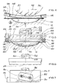
- 6 and 7 are rotating body 50 in the separation station 10 with which the individual pot-like containers 16 are separated from the film material web 20 can.
- Each rotating body 50 has a plate part 52, to which an annular cutting edge 54 is attached, projecting downward is.
- the free edge of the ring cutter 54 forms the Cutting edge 51.
- the rotary body 50 can by one central axis of rotation 53 are set in rotation (Arrow 56).
- the rotating body 50 can be be moved vertically onto the film material web 20 (Arrow 58).
- annular outer Hold-down device 66 available at the bottom of the ring-shaped Hold-down device 66 is an elastically flexible material 68 available. With the help of this material 68 the Foil material web 20 firmly on the transport plate 24.1 held while she, the web 20, by the ring cutter 54 is cut.
- an inner hold-down 72 may be arranged in the Interior 70, which is enclosed by the ring cutting edge 54.
- an inner hold-down 72 may be arranged in the Interior 70, which is enclosed by the ring cutting edge 54.
- the vacuum generator 38 still acts a sheet of film material 20, the same in the Arches 28 of the transport plate 24.1 keeps sucked.
- Knife edge in the form of a razor blade 80 In the embodiment shown in Fig. 7, the Knife edge in the form of a razor blade 80.
- the razor blade 80 is arranged with its cutting edge 82 so that they make an acute angle 84 with the surface the film material web 20 forms.
- fastening points 86 of the razor blade 80 on the rotating body 50.7 arranged accordingly.
- inner and outer hold-downs 66, 72, as in Described in connection with Fig. 5, can be provided.
- the serrated edge 62 or the serrated edge 64 could be dispensed with and instead the plate part 52 (FIG. 5) also at an acute angle 84 to the film material web 20 are arranged. Maintaining the axis of rotation 53 would then also be a pulling cut on the plate part 52 existing cutting edge 54 through the web 20 through are made possible. It would then be comparable Ratios as in the razor blade 80 exist.
Landscapes
- Engineering & Computer Science (AREA)
- Mechanical Engineering (AREA)
- Life Sciences & Earth Sciences (AREA)
- Forests & Forestry (AREA)
- Perforating, Stamping-Out Or Severing By Means Other Than Cutting (AREA)
- Control And Other Processes For Unpacking Of Materials (AREA)
Abstract
Description
- Fig. 1
- eine erste Ausführungsform einer Vorrichtung in perspektivisch auseinandergezogener Darstellung zum Herauslösen von Teilbereichen aus einem bahnartigen Folienmaterial mit einer topfartige Einwölbungen aufweisenden Transportplatte, in die von oben die zu zerteilende, zu aneinanderhängenden topfartigen Behältnissen verformte Folienmaterial-Bahn eingesetzt wird,
- Fig. 2
- eine Darstellung der in der Transportplatte einsitzenden Folienmaterial-Bahn gemäß Fig. 1,
- Fig. 3
- eine Darstellung des Trennvorganges der Folienmaterial-Bahn, bei der dieselbe in einer Wälzbewegung von mehreren, zu jeweils einem Ring geformten Messerschneiden zertrennt wird,
- Fig. 4
- eine vergrößerte Teilansicht der Darstellung gemäß Fig. 3,
- Fig. 5
- eine Teilansicht ähnlich der von Fig. 4, bei der die Vorrichtung eine rotierende Schneidkante besitzt, mittels der ein ziehender Schnitt durch die Folienmaterial-Bahn erzeugt werden kann, wobei die Schneidkante einen Zackenschliff besitzt,
- Fig. 6
- eine Teilansicht von Fig. 5 mit einer Messerschneide, die einen Wellenschliff besitzt, und
- Fig. 7
- eine Darstellung ähnlich der von Fig. 6 mit einer Messerschneide, die durch eine schräg positionierte Rasierklinge verwirklicht ist.
Claims (9)
- Vorrichtung (10) zum Herauslösen von Teilbereichen aus einem bahnartigen Folienmaterial (20),dadurch gekennzeichnet, dassmit einer Schneidkante (51, 82),die in einem ziehenden Schnitt durch die Folienmaterial-Bahn (20) hindurchziehbar ist,die in Richtung senkrecht zum Folienmaterial (20) in das Folienmaterial (20) hineinbewegbar ist,die in Rotation um eine Rotationsachse (53) bringbar ist,zumindest ein Niederhalter (66, 72) neben der Schneidkante (51, 82) vorhanden ist,der Niederhalter (66, 72) auf das Folienmaterial (20) pressbar ist.
- Vorrichtung nach Anspruch 1,
dadurch gekennzeichnet, dassdie Schneidkante (51, 82) im Grundriss kreisbogenförmig geformt ist, wobei der Mittelpunkt des Kreisbogens die Rotationsachse (53) ist. - Vorrichtung nach Anspruch 1 oder 2,
dadurch gekennzeichnet, dassim Innenraum (70), der von der kreisförmig rotierend antreibbaren Schneidkante (51, 82) umschlossen ist, ein innerer Niederhalter (72) vorhanden ist, der in Richtung zum Folienmaterial (20) nachgiebig gelagert ist. - Vorrichtung nach einem der Ansprüche 1 bis 3,
dadurch gekennzeichnet, dassim Außenraum, der den von der rotierend antreibbaren Schneidkante (51, 82) umschlossenen Raum außen umgibt, ein äußerer Niederhalter (66, 68) vorhanden ist. - Vorrichtung nach einem der Ansprüche 1 bis 4,
dadurch gekennzeichnet, dassdie Schneidkante (51) einen Zackenschliff besitzt. - Vorrichtung nach einem der Ansprüche 1 bis 4,
dadurch gekennzeichnet, dassdie Schneidkante (51) einen Wellenschliff besitzt. - Vorrichtung nach einem der Ansprüche 1 bis 6,
dadurch gekennzeichnet, dasszumindest eine Messerschneide (54, 80) an einem Rotationszylinder (50) vorhanden ist,der Rotationszylinder (50) in Rotation um eine Rotationsachse (53) bringbar ist,diese Rotationsachse durch die Längsachse des Rotationszylinders (50) geht,die Messerschneide (54, 80) in Richtung senkrecht zum Folienmaterial (20) in das Folienmaterial (20) hinein bewegbar ist. - Vorrichtung nach Anspruch 7,
dadurch gekennzeichnet, dassder Rotationszylinder (50) mit der Messerschneide (54, 80) in Richtung senkrecht zum Folienmaterial (20) bewegbar ist. - Vorrichtung nach einem der Ansprüche 7 oder 8,
dadurch gekennzeichnet, dassdie Messerschneide eine Rasierklinge (80) ist,die Längsachse der Rasierklinge in einem spitzen Winkel (84) zur Ebene der Folienmaterial-Bahn (20) vorhanden ist.
Applications Claiming Priority (3)
| Application Number | Priority Date | Filing Date | Title |
|---|---|---|---|
| DE29911914U | 1999-07-13 | ||
| DE29911914U DE29911914U1 (de) | 1999-07-13 | 1999-07-13 | Vorrichtung zum Herauslösen von Teilbereichen aus einem bahnartigen Folienmaterial |
| EP00113958A EP1068939B1 (de) | 1999-07-13 | 2000-07-01 | Vorrichtung zum Herauslösen von Teilbereichen aus einem bahnartigen Folienmaterial |
Related Parent Applications (1)
| Application Number | Title | Priority Date | Filing Date |
|---|---|---|---|
| EP00113958A Division EP1068939B1 (de) | 1999-07-13 | 2000-07-01 | Vorrichtung zum Herauslösen von Teilbereichen aus einem bahnartigen Folienmaterial |
Publications (2)
| Publication Number | Publication Date |
|---|---|
| EP1358976A1 true EP1358976A1 (de) | 2003-11-05 |
| EP1358976B1 EP1358976B1 (de) | 2006-01-04 |
Family
ID=8075857
Family Applications (2)
| Application Number | Title | Priority Date | Filing Date |
|---|---|---|---|
| EP00113958A Expired - Lifetime EP1068939B1 (de) | 1999-07-13 | 2000-07-01 | Vorrichtung zum Herauslösen von Teilbereichen aus einem bahnartigen Folienmaterial |
| EP03010440A Expired - Lifetime EP1358976B1 (de) | 1999-07-13 | 2000-07-01 | Vorrichtung zum Herauslösen von Teilbereichen aus einem bahnartigen Folienmaterial |
Family Applications Before (1)
| Application Number | Title | Priority Date | Filing Date |
|---|---|---|---|
| EP00113958A Expired - Lifetime EP1068939B1 (de) | 1999-07-13 | 2000-07-01 | Vorrichtung zum Herauslösen von Teilbereichen aus einem bahnartigen Folienmaterial |
Country Status (2)
| Country | Link |
|---|---|
| EP (2) | EP1068939B1 (de) |
| DE (3) | DE29911914U1 (de) |
Cited By (3)
| Publication number | Priority date | Publication date | Assignee | Title |
|---|---|---|---|---|
| CN110370364A (zh) * | 2019-08-12 | 2019-10-25 | 程慧玲 | 一种用于手机屏幕板生产的吸盘式工作台 |
| CN112109137A (zh) * | 2020-08-19 | 2020-12-22 | 豪能电子科技有限公司 | 一种适应无铅制程的覆铜箔层压板加工装置 |
| GB2589122A (en) * | 2019-11-21 | 2021-05-26 | Illinois Tool Works | Label cutter |
Families Citing this family (4)
| Publication number | Priority date | Publication date | Assignee | Title |
|---|---|---|---|---|
| DE102004052068B4 (de) * | 2004-10-26 | 2008-04-03 | GFD-Gesellschaft für Diamantprodukte mbH | Schneidwerkzeug und dessen Verwendung |
| DE202015008522U1 (de) | 2015-12-14 | 2016-01-19 | Harro Höfliger Verpackungsmaschinen GmbH | Vorrichtung zum Herauslösen von Teilbereichen aus einer Materialbahn |
| EP3246140B1 (de) * | 2016-05-16 | 2019-06-26 | Tetra Laval Holdings & Finance S.A. | Schneideeinheit und schneidverfahren |
| CH716982A1 (de) * | 2019-12-20 | 2021-06-30 | Rychiger Ag | Vorrichtung und Verfahren zum Schneiden von kreisförmigen Filterelementen aus einem Bandmaterial. |
Citations (4)
| Publication number | Priority date | Publication date | Assignee | Title |
|---|---|---|---|---|
| GB618008A (en) * | 1946-10-14 | 1949-02-15 | Jack Mitchell Buist | Rotary cutter for use in preparing ring test pieces of rubber and similar materials |
| DE1611733A1 (de) * | 1968-03-08 | 1971-01-28 | Union Verpackungs Gmbh | Vorrichtung an Verpackungsmaschinen |
| US3786564A (en) * | 1972-10-19 | 1974-01-22 | M Acheson | Carpet plug cutter |
| DE9206629U1 (de) * | 1992-05-15 | 1993-09-16 | Stema Baugeräte-Vertriebs- und Vermietungs GmbH, 25421 Pinneberg | Bohrwerkzeug |
Family Cites Families (6)
| Publication number | Priority date | Publication date | Assignee | Title |
|---|---|---|---|---|
| DE2254281A1 (de) * | 1972-11-06 | 1974-05-22 | Hillesheimer Walter Dipl Ing D | Vorrichtung zum stanzen von formlingen oder materialbahnen |
| US4043234A (en) * | 1976-11-24 | 1977-08-23 | Victor B. Godin, Trustee | Apparatus and method for cutting circles from sheet material |
| GB2032322A (en) * | 1978-05-19 | 1980-05-08 | Carr D | Cutting and creasing of blanks of cardboard or the like |
| JPH10258470A (ja) * | 1997-03-19 | 1998-09-29 | Kawakami Sangyo Kk | 分解性気泡シート |
| JPH1134184A (ja) * | 1997-07-15 | 1999-02-09 | Zenshindou Kogyo Kk | 紙器打抜き機 |
| SE514093C2 (sv) * | 1999-05-20 | 2001-01-08 | Sobi Hb | Förfarande för stansning av förpackningsmaterial och stansform samt användning därav |
-
1999
- 1999-07-13 DE DE29911914U patent/DE29911914U1/de not_active Expired - Lifetime
-
2000
- 2000-07-01 DE DE50012033T patent/DE50012033D1/de not_active Expired - Fee Related
- 2000-07-01 EP EP00113958A patent/EP1068939B1/de not_active Expired - Lifetime
- 2000-07-01 DE DE50005385T patent/DE50005385D1/de not_active Expired - Fee Related
- 2000-07-01 EP EP03010440A patent/EP1358976B1/de not_active Expired - Lifetime
Patent Citations (4)
| Publication number | Priority date | Publication date | Assignee | Title |
|---|---|---|---|---|
| GB618008A (en) * | 1946-10-14 | 1949-02-15 | Jack Mitchell Buist | Rotary cutter for use in preparing ring test pieces of rubber and similar materials |
| DE1611733A1 (de) * | 1968-03-08 | 1971-01-28 | Union Verpackungs Gmbh | Vorrichtung an Verpackungsmaschinen |
| US3786564A (en) * | 1972-10-19 | 1974-01-22 | M Acheson | Carpet plug cutter |
| DE9206629U1 (de) * | 1992-05-15 | 1993-09-16 | Stema Baugeräte-Vertriebs- und Vermietungs GmbH, 25421 Pinneberg | Bohrwerkzeug |
Cited By (6)
| Publication number | Priority date | Publication date | Assignee | Title |
|---|---|---|---|---|
| CN110370364A (zh) * | 2019-08-12 | 2019-10-25 | 程慧玲 | 一种用于手机屏幕板生产的吸盘式工作台 |
| GB2589122A (en) * | 2019-11-21 | 2021-05-26 | Illinois Tool Works | Label cutter |
| GB2589163A (en) * | 2019-11-21 | 2021-05-26 | Illinois Tool Works | Label cutter |
| GB2589122B (en) * | 2019-11-21 | 2022-01-26 | Illinois Tool Works | Label cutter |
| US11602869B2 (en) | 2019-11-21 | 2023-03-14 | Illinois Tool Works Inc. | Label cutter |
| CN112109137A (zh) * | 2020-08-19 | 2020-12-22 | 豪能电子科技有限公司 | 一种适应无铅制程的覆铜箔层压板加工装置 |
Also Published As
| Publication number | Publication date |
|---|---|
| EP1358976B1 (de) | 2006-01-04 |
| EP1068939A3 (de) | 2001-08-08 |
| DE50005385D1 (de) | 2004-04-01 |
| EP1068939A2 (de) | 2001-01-17 |
| DE29911914U1 (de) | 1999-09-09 |
| EP1068939B1 (de) | 2004-02-25 |
| DE50012033D1 (de) | 2006-03-30 |
Similar Documents
| Publication | Publication Date | Title |
|---|---|---|
| DE2935122C2 (de) | Vorrichtung zum Herstellen von Briefumschlägen aus einer zusammenhängenden Papierbahn und zum Füllen dieser Briefumschläge mit Einlagen | |
| DE3045095C2 (de) | Vorrichtung zum Entfernen von Stanzabfall beim Stanzen von Bögen | |
| DE3814448C2 (de) | ||
| DE3444394C2 (de) | ||
| EP1185398B1 (de) | Zwischenblattzuführeinrichtung für aufschnittschneidemaschine | |
| DE69315337T2 (de) | Maschine zum schneiden von bogen aus einer papierbahn und zum gleichzeitigen schneiden eines querstreifens | |
| EP0367715A1 (de) | Verfahren und Vorrichtung zum Beschneiden von Druckprodukten | |
| DE3220461A1 (de) | Vorrichtung zum einbringen von loechern in dicke papierstapel | |
| DE2254262C2 (de) | Vorrichtung zum Anbringen von Beschlägen auf Werkstücken | |
| DE10047545B4 (de) | Schneid- und Transportwalze mit integrierter Schneidvorrichtung mit schwenkbaren Schneidflächen und Verfahren zum Schneiden von Materialbahnen mithilfe einer solchen Walze | |
| DE4338561A1 (de) | Vorrichtung zur Vorbereitung/Vorbehandlung verpreßbarer Hohlkörper für Recycling | |
| EP1068939B1 (de) | Vorrichtung zum Herauslösen von Teilbereichen aus einem bahnartigen Folienmaterial | |
| EP0065179B1 (de) | Vorrichtung zum Einstanzen eines Loches in eine Papierbahn | |
| DE2811706A1 (de) | Verfahren und vorrichtung zum abziehen eines zusammenhaengenden steges vom rand eines koerpers | |
| DE1502998A1 (de) | Schrottzerkleinerer fuer Seitenbesaeumscheren | |
| EP0395941A1 (de) | Vorrichtung zum Entleeren von mit Schüttgut gefüllten Säcken | |
| DE2558835A1 (de) | Verfahren und vorrichtung zum schneiden von band- oder plattenfoermigem material | |
| DE19927920A1 (de) | Schneideinrichtung im Falzapparat einer Rotationsdruckmaschine und Falzapparat mit einer solchen Schneideinrichtung | |
| DE2047920C3 (de) | Vorrichtung zum Trennen von Stanznuten in Form von Einzelkarten vom Stanzmaterial | |
| DE2354464C2 (de) | Reifen-Zerteilmaschine | |
| DE2553539C2 (de) | Verfahren und Vorrichtung zum Zerteilen eines gebrauchten Luftreifens | |
| EP3181311A1 (de) | Vorrichtung zum herauslösen von teilbereichen aus einer materialbahn | |
| DE2632425C3 (de) | Maschine zum öffnen von Briefumschlägen | |
| DE2733626A1 (de) | Schneideinrichtung fuer verpackungsmaschinen | |
| DE102015005559B4 (de) | Schneidevorrichtung mit zumindest zwei Obermessern zum Herausschneiden eines Streifens einer Folie |
Legal Events
| Date | Code | Title | Description |
|---|---|---|---|
| PUAI | Public reference made under article 153(3) epc to a published international application that has entered the european phase |
Free format text: ORIGINAL CODE: 0009012 |
|
| AC | Divisional application: reference to earlier application |
Ref document number: 1068939 Country of ref document: EP Kind code of ref document: P |
|
| AK | Designated contracting states |
Kind code of ref document: A1 Designated state(s): DE GB IT NL |
|
| 17P | Request for examination filed |
Effective date: 20040306 |
|
| AKX | Designation fees paid |
Designated state(s): DE GB IT NL |
|
| 17Q | First examination report despatched |
Effective date: 20040823 |
|
| GRAP | Despatch of communication of intention to grant a patent |
Free format text: ORIGINAL CODE: EPIDOSNIGR1 |
|
| GRAS | Grant fee paid |
Free format text: ORIGINAL CODE: EPIDOSNIGR3 |
|
| GRAA | (expected) grant |
Free format text: ORIGINAL CODE: 0009210 |
|
| AC | Divisional application: reference to earlier application |
Ref document number: 1068939 Country of ref document: EP Kind code of ref document: P |
|
| AK | Designated contracting states |
Kind code of ref document: B1 Designated state(s): DE GB IT NL |
|
| REG | Reference to a national code |
Ref country code: GB Ref legal event code: FG4D Free format text: NOT ENGLISH |
|
| GBT | Gb: translation of ep patent filed (gb section 77(6)(a)/1977) |
Effective date: 20060222 |
|
| REF | Corresponds to: |
Ref document number: 50012033 Country of ref document: DE Date of ref document: 20060330 Kind code of ref document: P |
|
| PLBE | No opposition filed within time limit |
Free format text: ORIGINAL CODE: 0009261 |
|
| STAA | Information on the status of an ep patent application or granted ep patent |
Free format text: STATUS: NO OPPOSITION FILED WITHIN TIME LIMIT |
|
| 26N | No opposition filed |
Effective date: 20061005 |
|
| PGFP | Annual fee paid to national office [announced via postgrant information from national office to epo] |
Ref country code: DE Payment date: 20070724 Year of fee payment: 8 |
|
| PGFP | Annual fee paid to national office [announced via postgrant information from national office to epo] |
Ref country code: GB Payment date: 20070730 Year of fee payment: 8 |
|
| PGFP | Annual fee paid to national office [announced via postgrant information from national office to epo] |
Ref country code: IT Payment date: 20070727 Year of fee payment: 8 Ref country code: NL Payment date: 20070717 Year of fee payment: 8 |
|
| GBPC | Gb: european patent ceased through non-payment of renewal fee |
Effective date: 20080701 |
|
| NLV4 | Nl: lapsed or anulled due to non-payment of the annual fee |
Effective date: 20090201 |
|
| PG25 | Lapsed in a contracting state [announced via postgrant information from national office to epo] |
Ref country code: DE Free format text: LAPSE BECAUSE OF NON-PAYMENT OF DUE FEES Effective date: 20090203 |
|
| PG25 | Lapsed in a contracting state [announced via postgrant information from national office to epo] |
Ref country code: NL Free format text: LAPSE BECAUSE OF NON-PAYMENT OF DUE FEES Effective date: 20090201 |
|
| PG25 | Lapsed in a contracting state [announced via postgrant information from national office to epo] |
Ref country code: GB Free format text: LAPSE BECAUSE OF NON-PAYMENT OF DUE FEES Effective date: 20080701 |
|
| PG25 | Lapsed in a contracting state [announced via postgrant information from national office to epo] |
Ref country code: IT Free format text: LAPSE BECAUSE OF NON-PAYMENT OF DUE FEES Effective date: 20080701 |