EP1352182B1 - Courroie - Google Patents
Courroie Download PDFInfo
- Publication number
- EP1352182B1 EP1352182B1 EP00991283A EP00991283A EP1352182B1 EP 1352182 B1 EP1352182 B1 EP 1352182B1 EP 00991283 A EP00991283 A EP 00991283A EP 00991283 A EP00991283 A EP 00991283A EP 1352182 B1 EP1352182 B1 EP 1352182B1
- Authority
- EP
- European Patent Office
- Prior art keywords
- belt
- carrier
- elements
- pulley
- limb
- Prior art date
- Legal status (The legal status is an assumption and is not a legal conclusion. Google has not performed a legal analysis and makes no representation as to the accuracy of the status listed.)
- Expired - Lifetime
Links
- 230000005540 biological transmission Effects 0.000 claims description 36
- 230000001965 increasing effect Effects 0.000 claims description 20
- 238000003780 insertion Methods 0.000 claims description 4
- 230000037431 insertion Effects 0.000 claims description 4
- 230000006978 adaptation Effects 0.000 claims description 2
- 238000013461 design Methods 0.000 description 41
- 230000000694 effects Effects 0.000 description 21
- 238000010276 construction Methods 0.000 description 11
- 238000004519 manufacturing process Methods 0.000 description 10
- 230000008901 benefit Effects 0.000 description 8
- 238000012937 correction Methods 0.000 description 8
- 230000009467 reduction Effects 0.000 description 7
- 238000005452 bending Methods 0.000 description 4
- 230000002349 favourable effect Effects 0.000 description 4
- 230000009977 dual effect Effects 0.000 description 3
- 230000005489 elastic deformation Effects 0.000 description 3
- 239000002184 metal Substances 0.000 description 3
- 241000282326 Felis catus Species 0.000 description 2
- 230000002411 adverse Effects 0.000 description 2
- 239000002826 coolant Substances 0.000 description 2
- 238000011161 development Methods 0.000 description 2
- 238000007493 shaping process Methods 0.000 description 2
- 238000012546 transfer Methods 0.000 description 2
- 230000009471 action Effects 0.000 description 1
- 230000006835 compression Effects 0.000 description 1
- 238000007906 compression Methods 0.000 description 1
- 238000001816 cooling Methods 0.000 description 1
- 230000002708 enhancing effect Effects 0.000 description 1
- 239000012530 fluid Substances 0.000 description 1
- 230000005484 gravity Effects 0.000 description 1
- 239000003999 initiator Substances 0.000 description 1
- 238000012423 maintenance Methods 0.000 description 1
- 239000000463 material Substances 0.000 description 1
- 238000000034 method Methods 0.000 description 1
- 230000002093 peripheral effect Effects 0.000 description 1
- 230000008569 process Effects 0.000 description 1
- 230000001737 promoting effect Effects 0.000 description 1
- 230000000284 resting effect Effects 0.000 description 1
- 239000011435 rock Substances 0.000 description 1
- 238000000926 separation method Methods 0.000 description 1
- 239000007787 solid Substances 0.000 description 1
- 230000008719 thickening Effects 0.000 description 1
Images


Classifications
-
- F—MECHANICAL ENGINEERING; LIGHTING; HEATING; WEAPONS; BLASTING
- F16—ENGINEERING ELEMENTS AND UNITS; GENERAL MEASURES FOR PRODUCING AND MAINTAINING EFFECTIVE FUNCTIONING OF MACHINES OR INSTALLATIONS; THERMAL INSULATION IN GENERAL
- F16G—BELTS, CABLES, OR ROPES, PREDOMINANTLY USED FOR DRIVING PURPOSES; CHAINS; FITTINGS PREDOMINANTLY USED THEREFOR
- F16G5/00—V-belts, i.e. belts of tapered cross-section
- F16G5/16—V-belts, i.e. belts of tapered cross-section consisting of several parts
Definitions
- the power transmitting capacity is optimised by the reduction on overall limb width, particularly in relation to the nominal element width, implying the width of the element at the rocking edge, which is generally proportional to an axial width of the carrier.
- the measure according to the invention allows the saddle surface to be relatively increased, which is favourable since thereby the width of the carrier may be increased and accordingly its thickness reduced.
- the carrier is composed of a set of radially stacked endless rings. It being recognised by the invention that radial outer rings of such set tends to contribute less to the power transmitting capacity than the radial inner rings.
- a reduction in number of rings may then be favoured over a small increase in the axial width of the carrier.
- the number of rings also has a large influence on cost.
- the width of the individual limbs at a level at or near the saddle surface is set at less than one-twelfth the axial width of said surface.
- the belt may at stand still of a transmission be incorporated without the presence of a pre-tensioning spring in a pulley, since the wedging feature prevents the elements located at a transmissions upper side with respect to the earth's gravity from assuming a position from which the belt may no longer deform to a desired rod like condition.
- the wedging feature aids in assuming a stable inwardly curved end position of the slack trajectory.
- the limbs 10 and 11 extend upwardly up to and slightly beyond the carrier 4 when it contacts the saddle surface 8 of the element 5.
- the hook parts 12 and 13 of the prior art limbs 10 and 11 are shaped to contain the carrier in the recess 6 once the belt 3 is assembled.
- the element 5 is provided with flanks 15 and 16, and with a tapering enabling the belt 3 to pass along the arc-shaped bent trajectory part B T in a pulley 1, 2.
- the rocking edge 9 is positioned somewhat below, i.e. radially inward from, the saddle surface 8.
- the tapering is realised by the inclined face 19 of the lower element part, which links up with a lower side of the rocking edge 9, being inclined downward and rearward relative to a principal plane part extending above the axially oriented rocking edge 9.
- the lower element part is otherwise produced as a solid essentially trapezoid shaped block with relatively high stiffness that has an essentially straight lower edge that is oriented in the axial direction.
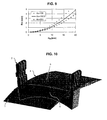
- Figure 8 elucidates the feature of a critical radial distance or height, whereby an insight in a belts geometrical features is favourably identified and applied in a new design, thereby utilising ordinary mathematical law.
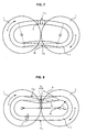
- the upper crossing trajectory C TU represents the slack trajectory part, where for taking into account the worst case the total end play E P is concentrated between two adjacent elements 5 that are located exactly halfway the slack trajectory part.
- the transmission is depicted with the belt 3 in Medium transmission condition, i.e. wherein a ratio of speed transfer and a ratio of torque transfer is 1.
- Arrow A originates at the upper side of the rocking edge 9 of an element 5 at the location of exit of the belt 3 from the relevant pulley 2.
- the elements 5 are provided with relatively long extending limbs 10 and 11, as measured in the radial direction starting from the rocking edge 9 that are part of the upper element part.
- this feature of the elements 5 is applied in combination with the above-described increasing thickness feature of the upper element part, as shown in figure 6.
- the limbs 10 and 11 extend above the rocking edge 9 up to a level beyond a critical radial distance, or height H SE , considered part of the present invention.
- the critical radial height H SE above rocking edge 9 depends on a pre-defined desired amount of end play correction E PC .
- the circumference length L of the belt 3 in practise proves to be a valuable and in automotive application sufficient indicator for the sometimes more preferred parameter indicating the centre distance A V between the shafts, i.e. the axial centres of the transmission's pulleys 1 and 2, as a result of a generally desired closest mutual orientation of pulley's.
- the distance between the pulley's peripheries can be considered negligible in relation to the belt's actual circumference, i.e. generally being smaller than about 1%.
- this means that the pulleys 1 and 2 are usually mutually positioned at the smallest radial distance possible.
- the end play removing ability of the height H SE according to equation (1) may then be translated to a design requirement for the belt 3.
- element play values are according to the invention safely set at 1.5 mm for elastic deformations and 2 mm for wear effects respectively, whereas the element play value in the assembled free state of the belt 3 is taken as 1.5 mm, to which for the present calculating purpose a safety margin is set of 0.5 mm.
- a safety margin is set of 0.5 mm.
Landscapes
- Engineering & Computer Science (AREA)
- General Engineering & Computer Science (AREA)
- Mechanical Engineering (AREA)
- Devices For Conveying Motion By Means Of Endless Flexible Members (AREA)
- Transmissions By Endless Flexible Members (AREA)
Claims (13)
- Courroie (3) destinée à une transmission à variation continue, comprenant un support sans fin (4) soumis aux forces de traction au sein de ladite courroie (3) et une pluralité d'éléments transversaux (5) mobiles dans la direction longitudinale le long dudit support (4), lesquels éléments (5) sont munis d'au moins une surface bombée (8) destinée à venir en contact avec le support (4), laquelle surface bombée (8) définit une position mutuelle ultime du support (4) et des éléments (5) l'un par rapport à l'autre au sein de la courroie (3) dans la direction radiale, et d'une partie d' élément inférieur biseauté comprenant un bord de basculement (9), étant entendu que chaque extrémité axiale de la surface bombée (8) est attenante à une branche (10; 11) formant une protubérance se prolongeant essentiellement dans la direction radiale extérieure, en définissant ainsi une cavité (6) ouverte à l'extrémité radiale extérieure de l'élément (5), ce qui permet l'insertion libre du support (4) dans cette cavité, étant entendu que chaque branche se prolonge radialement vers l'extérieur au-delà du support (4) sur une distance essentiellement égale ou supérieure à une épaisseur longitudinale de l'élément (5) à l'emplacement de la surface bombée (8), au moins lors que le support (4) et la surface bombée (8) sont en contact mutuel, alors que les éléments transversaux (5) sont en outre munis d'une face de contact de poulie (15, 16) à chacun de leurs cotes axiaux afin de venir en contact avec un réa de poulie de la transmission, lesquelles faces de contact de poulie (15, 16) sont mutuellement orientées sous un angle de flanc et lesquelles faces de contact de poulie (15, 16) se prolongent radialement vers l'extérieur au-delà du support (4), au moins lorsque le support (4) et la surface bombée (8) sont en contact mutuel, caractérisée en ce que les branches (10, 11) présentent chacune une face axiale se prolongeant dans une direction essentiellement radiale sous un petit angle positif, laquelle direction radiale correspondant essentiellement à l'angle de flanc, ladite face axiale se prolongeant radialement vers l'extérieur au- delà des faces de contact de poulie (15, 16).
- Courroie (3) selon la revendication 1, caractérisée en ce qu'une largeur axiale de chaque branche (10, 11), concernant au moins une partie radialement la plus intérieure de celles-ci, est inférieure au douzième d'une largeur axiale de l'élément (5) au niveau du bord de basculement (9).
- Courroie (3) selon la revendication 1 ou 2, caractérisée en ce qu'une largeur axiale de chaque branche (10, 11), concernant au moins une partie radialement la plus intérieure de celles-ci, est comprise dans des plages allant de 1 à 5 fois l'épaisseur longitudinale de l'élément (5).
- Courroie (3) selon l'une quelconque des revendications précédentes, caractérisée en ce que chaque face de contact de poulie (15, 16) se prolonge sur au moins un tiers, de préférence sur environ la moitié de sa hauteur radiale au-delà du bord de basculement (9).
- Courroie (3) selon l'une quelconque des revendications précédentes, caractérisée en ce que chaque face de contact de poulie (15, 16) se prolonge sur au moins la moitié environ de la dimension radiale de l'élément (5).
- Courroie (3) selon l'une quelconque des revendications précédentes, caractérisée en ce que les branches (10, 11) comprennent une partie radialement extérieure dont la largeur axiale est plus importante qu'une largeur axiale d'une partie radialement la plus intérieure de la branche respective (10 ; 11).
- Courroie (3) selon la revendication 6, caractérisée en ce que la partie radialement extérieure de chaque branche (10 ; 11) de largeur axiale plus importante présente une face faisant face à la cavité (6) qui se prolonge essentiellement dans la direction radiale.
- Courroie (3) selon la revendication 6 ou 7, caractérisée en ce que la partie radialement extérieure de chaque branche (10 ; 11) se prolonge axialement en chevauchant partiellement la surface bombée (8).
- Courroie (3) selon l'une quelconque des revendications précédentes, caractérisée en ce que chaque branche (10; 11) est munie de protubérances longitudinales formant encoche (21) disposées radialement vers l'extérieur, au-delà du support (4), au moins lorsque le support (4) et la surface bombée (8) sont en contact mutuel.
- Courroie (3) selon la revendication 9, caractérisée en ce que les branches (10; 11) comprennent une partie radialement extérieure, présentant une largeur axiale plus importante qu'une largeur axiale d'une partie radialement la plus intérieure de la branche respective (10 ; 11), qui est située au moins partiellement radialement à l'extérieur, au-delà de la protubérance longitudinale formant encoche (21).
- Courroie (3) selon l'une quelconque des revendications précédentes, caractérisée en ce qu'une adaptation d'une hauteur radiale critique HSE des branches (10, 11) d'au moins une majorité des éléments (5) de la courroie (3) relativement à une longueur circonférentielle L de la courroie (3) permet d'éliminer une certaine quantité de jeu (EPC) présent entre les éléments transversaux (5), au moins potentiellement après montage et en fonctionnement dans une transmission par contact mutuel entre les branches (10, 11) d'au moins deux éléments transversaux (5) dans une partie concave de la courroie (3) à trajectoire lâche entre les poulies (1, 2).
- Courroie (3) selon l'une quelconque des revendications précédentes, caractérisée en ce qu'une épaisseur des branches (10, 11) d'une majorité des éléments transversaux (5) dans la direction longitudinale de la courroie (3) est significativement plus importante qu'une épaisseur la plus importante de la partie d'élément inférieur biseauté, de telle manière qu'une série d'éléments (5) poussés les uns contre les autres au sein de la courroie (3) en contact mutuel au travers de leurs parties supérieures d'élément (10, 11; 14) prend une forme bombée.
- Courroie (3) selon l'une quelconque des revendications précédentes, caractérisée en ce que le bord de basculement (9) est formé par une courbure convexe à prolongement axial dont le rayon est d'au moins 12 mm, de préférence supérieur à 18 mm, lorsqu'il est mesuré vu de côté.
Applications Claiming Priority (1)
| Application Number | Priority Date | Filing Date | Title |
|---|---|---|---|
| PCT/EP2000/013376 WO2002053936A1 (fr) | 2000-12-28 | 2000-12-28 | Courroie |
Publications (2)
| Publication Number | Publication Date |
|---|---|
| EP1352182A1 EP1352182A1 (fr) | 2003-10-15 |
| EP1352182B1 true EP1352182B1 (fr) | 2004-11-10 |
Family
ID=8164238
Family Applications (1)
| Application Number | Title | Priority Date | Filing Date |
|---|---|---|---|
| EP00991283A Expired - Lifetime EP1352182B1 (fr) | 2000-12-28 | 2000-12-28 | Courroie |
Country Status (5)
| Country | Link |
|---|---|
| US (1) | US7108624B2 (fr) |
| EP (1) | EP1352182B1 (fr) |
| JP (1) | JP4502578B2 (fr) |
| DE (1) | DE60015818T2 (fr) |
| WO (1) | WO2002053936A1 (fr) |
Families Citing this family (18)
| Publication number | Priority date | Publication date | Assignee | Title |
|---|---|---|---|---|
| JP4511913B2 (ja) * | 2004-12-08 | 2010-07-28 | 本田技研工業株式会社 | 金属ベルト用金属リングの自由状態径設定方法 |
| JP4424376B2 (ja) * | 2007-06-06 | 2010-03-03 | トヨタ自動車株式会社 | 伝動ベルト |
| JP4862844B2 (ja) * | 2008-02-28 | 2012-01-25 | トヨタ自動車株式会社 | ベルト組立装置およびベルト組立方法 |
| JP5693465B2 (ja) * | 2008-12-19 | 2015-04-01 | ローベルト ボツシユ ゲゼルシヤフト ミツト ベシユレンクテル ハフツングRobert Bosch Gmbh | 駆動ベルト |
| DE112009005389T5 (de) * | 2009-11-19 | 2012-09-13 | Toyota Jidosha Kabushiki Kaisha | Übertragungsriemen |
| NL1039559C2 (en) * | 2012-04-23 | 2013-10-28 | Bosch Gmbh Robert | Belt-and-pulley-type continuously variable transmission. |
| DE112012006666T5 (de) * | 2012-07-06 | 2015-03-19 | Honda Motor Co., Ltd. | Element für metallischen Riemen |
| NL1041121B1 (en) * | 2014-12-23 | 2016-10-11 | Bosch Gmbh Robert | A pushbelt for a continuously variable transmission and a transmission provided therewith. |
| CN108431452B (zh) * | 2016-02-12 | 2020-08-18 | 爱信艾达株式会社 | 传动带 |
| EP3358215A4 (fr) * | 2016-02-12 | 2018-12-05 | Aisin AW Co., Ltd. | Courroie de transmission |
| US11047451B2 (en) * | 2016-05-18 | 2021-06-29 | Aisin Aw Co., Ltd. | Transmission belt |
| US11149820B2 (en) * | 2017-03-03 | 2021-10-19 | Aisin Aw Co., Ltd. | Element designing method and power transfer belt |
| JP6809368B2 (ja) * | 2017-05-16 | 2021-01-06 | アイシン・エィ・ダブリュ株式会社 | 無段変速機および伝動ベルト |
| WO2018221714A1 (fr) * | 2017-06-02 | 2018-12-06 | アイシン・エィ・ダブリュ株式会社 | Élément de courroie de transmission et courroie de transmission |
| JP6740962B2 (ja) * | 2017-06-09 | 2020-08-19 | アイシン・エィ・ダブリュ株式会社 | 伝動ベルトおよび伝動ベルト用エレメント |
| WO2019035360A1 (fr) * | 2017-08-14 | 2019-02-21 | アイシン・エィ・ダブリュ株式会社 | Élément de courroie de transmission et courroie de transmission |
| JP6621495B2 (ja) * | 2018-04-03 | 2019-12-18 | 本田技研工業株式会社 | 無段変速機用金属エレメントおよび無段変速機用金属エレメントの製造方法 |
| NL1043501B1 (en) * | 2019-12-10 | 2021-08-31 | Bosch Gmbh Robert | A transverse segment for a drive belt and a drive belt for a continuously variable transmission including the transverse segment and a ring stack |
Family Cites Families (19)
| Publication number | Priority date | Publication date | Assignee | Title |
|---|---|---|---|---|
| GB655173A (en) * | 1947-03-12 | 1951-07-11 | Friederike Peter | Improvements in v-belts |
| US3720113A (en) | 1971-04-06 | 1973-03-13 | Doorne H Van | Flexible continuous power transmission means |
| NL168307C (nl) | 1977-08-04 | 1982-03-16 | Doornes Transmissie Bv | Drijfriem. |
| NL7900923A (nl) * | 1979-02-06 | 1980-08-08 | Doornes Transmissie Bv | Samengestelde drijfriem voorzien van dwarselementen met koppelingsmiddelen, en dwarselement voor een drijfriem. |
| JPS5834253A (ja) | 1981-08-24 | 1983-02-28 | Nissan Motor Co Ltd | 伝動vベルト |
| US4465469A (en) | 1982-05-21 | 1984-08-14 | General Motors Corporation | Drive block for a continuous metal band drive belt |
| JPS59190540A (ja) | 1983-04-14 | 1984-10-29 | Toyota Motor Corp | 動力伝達用無端ベルト |
| NL8302959A (nl) | 1983-08-24 | 1985-03-18 | Gayliene Investments Ltd | Drijfband. |
| JPS62840U (fr) * | 1985-06-19 | 1987-01-07 | ||
| JPH0830517B2 (ja) * | 1987-10-12 | 1996-03-27 | 日本発条株式会社 | 伝動ベルト用ブロック |
| JPH0723643Y2 (ja) * | 1989-11-16 | 1995-05-31 | 本田技研工業株式会社 | 金属vベルト |
| JPH0733003Y2 (ja) * | 1990-07-11 | 1995-07-31 | 本田技研工業株式会社 | 伝動用vベルト |
| JP3715126B2 (ja) | 1998-04-10 | 2005-11-09 | 本田技研工業株式会社 | 無段変速機用ベルト |
| ES2189083T3 (es) | 1998-07-30 | 2003-07-01 | Doornes Transmissie Bv | Correa de transmision. |
| JP3527418B2 (ja) | 1998-08-31 | 2004-05-17 | 本田技研工業株式会社 | 金属vベルト |
| EP1132649B1 (fr) * | 1998-11-05 | 2005-02-02 | Fukuju Kogyo Kabushiki Kaisha | Element de courroie metallique |
| JP4178643B2 (ja) | 1999-01-27 | 2008-11-12 | 日産自動車株式会社 | ベルト式無段変速機 |
| EP1221561A1 (fr) * | 2000-12-28 | 2002-07-10 | Van Doorne's Transmissie B.V. | Courroie de transmission |
| DE60043940D1 (de) * | 2000-12-28 | 2010-04-15 | Bosch Transmission Technology | Treibriemen |
-
2000
- 2000-12-28 JP JP2002554412A patent/JP4502578B2/ja not_active Expired - Lifetime
- 2000-12-28 WO PCT/EP2000/013376 patent/WO2002053936A1/fr not_active Ceased
- 2000-12-28 US US10/451,984 patent/US7108624B2/en not_active Expired - Fee Related
- 2000-12-28 DE DE60015818T patent/DE60015818T2/de not_active Expired - Lifetime
- 2000-12-28 EP EP00991283A patent/EP1352182B1/fr not_active Expired - Lifetime
Also Published As
| Publication number | Publication date |
|---|---|
| JP2004517273A (ja) | 2004-06-10 |
| DE60015818D1 (de) | 2004-12-16 |
| US7108624B2 (en) | 2006-09-19 |
| WO2002053936A1 (fr) | 2002-07-11 |
| JP4502578B2 (ja) | 2010-07-14 |
| US20040082417A1 (en) | 2004-04-29 |
| EP1352182A1 (fr) | 2003-10-15 |
| DE60015818T2 (de) | 2005-11-24 |
Similar Documents
| Publication | Publication Date | Title |
|---|---|---|
| EP1219860B1 (fr) | Courroie de transmission | |
| US7066858B2 (en) | Belt | |
| EP1352182B1 (fr) | Courroie | |
| EP1158210A1 (fr) | Transmission variable de manière continue, courroie sans fin de transmission de couple et poulie réglable | |
| WO2018122398A1 (fr) | Segment transversal pour courroie d'entraînement destiné à une transmission à variation continue | |
| KR100479279B1 (ko) | 다중 리브형 무단 변속기 벨트 | |
| US6830525B1 (en) | Belt | |
| EP1544502B1 (fr) | Courroie de transmission | |
| WO2002053935A1 (fr) | Courroie | |
| WO2002053938A1 (fr) | Courroie | |
| JP5044416B2 (ja) | 駆動ベルト | |
| WO2002053937A1 (fr) | Courroie | |
| EP3505790A1 (fr) | Segment transversal de courroie d'entraînement pour une transmission à variation continue et courroie d'entraînement l'incluant | |
| EP1085235A1 (fr) | Courroie | |
| EP2659160B1 (fr) | Élément transversal destiné à une courroie de transmission pour une transmission à variation continue dotée de deux parties de surface de contact sur l'un de ses côtés latéraux | |
| JP2008519209A (ja) | 凸面プーリシーブと駆動ベルトを備えた変速機 | |
| KR100606986B1 (ko) | 연속 가변식 트랜스미션 | |
| WO2021129954A1 (fr) | Courroie d'entraînement pourvue d'une pluralité de segments transversaux et d'un empilement annulaire confiné dans une ouverture centrale de ces segments transversaux | |
| JP2006022921A (ja) | ベルト式無段変速機のエレメント形状 |
Legal Events
| Date | Code | Title | Description |
|---|---|---|---|
| PUAI | Public reference made under article 153(3) epc to a published international application that has entered the european phase |
Free format text: ORIGINAL CODE: 0009012 |
|
| 17P | Request for examination filed |
Effective date: 20030728 |
|
| AK | Designated contracting states |
Kind code of ref document: A1 Designated state(s): AT BE CH CY DE DK ES FI FR GB GR IE IT LI LU MC NL PT SE TR |
|
| GRAP | Despatch of communication of intention to grant a patent |
Free format text: ORIGINAL CODE: EPIDOSNIGR1 |
|
| RBV | Designated contracting states (corrected) |
Designated state(s): DE FR GB NL |
|
| GRAA | (expected) grant |
Free format text: ORIGINAL CODE: 0009210 |
|
| GRAS | Grant fee paid |
Free format text: ORIGINAL CODE: EPIDOSNIGR3 |
|
| AK | Designated contracting states |
Kind code of ref document: B1 Designated state(s): DE FR GB NL |
|
| REG | Reference to a national code |
Ref country code: GB Ref legal event code: FG4D |
|
| REG | Reference to a national code |
Ref country code: IE Ref legal event code: FG4D |
|
| REF | Corresponds to: |
Ref document number: 60015818 Country of ref document: DE Date of ref document: 20041216 Kind code of ref document: P |
|
| PLBE | No opposition filed within time limit |
Free format text: ORIGINAL CODE: 0009261 |
|
| STAA | Information on the status of an ep patent application or granted ep patent |
Free format text: STATUS: NO OPPOSITION FILED WITHIN TIME LIMIT |
|
| ET | Fr: translation filed | ||
| 26N | No opposition filed |
Effective date: 20050811 |
|
| REG | Reference to a national code |
Ref country code: FR Ref legal event code: PLFP Year of fee payment: 16 |
|
| PGFP | Annual fee paid to national office [announced via postgrant information from national office to epo] |
Ref country code: GB Payment date: 20151221 Year of fee payment: 16 |
|
| PGFP | Annual fee paid to national office [announced via postgrant information from national office to epo] |
Ref country code: FR Payment date: 20151218 Year of fee payment: 16 Ref country code: NL Payment date: 20151221 Year of fee payment: 16 |
|
| PGFP | Annual fee paid to national office [announced via postgrant information from national office to epo] |
Ref country code: DE Payment date: 20160224 Year of fee payment: 16 |
|
| REG | Reference to a national code |
Ref country code: DE Ref legal event code: R119 Ref document number: 60015818 Country of ref document: DE |
|
| REG | Reference to a national code |
Ref country code: NL Ref legal event code: MM Effective date: 20170101 |
|
| GBPC | Gb: european patent ceased through non-payment of renewal fee |
Effective date: 20161228 |
|
| PG25 | Lapsed in a contracting state [announced via postgrant information from national office to epo] |
Ref country code: NL Free format text: LAPSE BECAUSE OF NON-PAYMENT OF DUE FEES Effective date: 20170101 |
|
| REG | Reference to a national code |
Ref country code: FR Ref legal event code: ST Effective date: 20170831 |
|
| PG25 | Lapsed in a contracting state [announced via postgrant information from national office to epo] |
Ref country code: FR Free format text: LAPSE BECAUSE OF NON-PAYMENT OF DUE FEES Effective date: 20170102 |
|
| PG25 | Lapsed in a contracting state [announced via postgrant information from national office to epo] |
Ref country code: GB Free format text: LAPSE BECAUSE OF NON-PAYMENT OF DUE FEES Effective date: 20161228 Ref country code: DE Free format text: LAPSE BECAUSE OF NON-PAYMENT OF DUE FEES Effective date: 20170701 |