EP1342874A2 - Möbelscharnier mit Verstelleinrichtung - Google Patents
Möbelscharnier mit Verstelleinrichtung Download PDFInfo
- Publication number
- EP1342874A2 EP1342874A2 EP03004625A EP03004625A EP1342874A2 EP 1342874 A2 EP1342874 A2 EP 1342874A2 EP 03004625 A EP03004625 A EP 03004625A EP 03004625 A EP03004625 A EP 03004625A EP 1342874 A2 EP1342874 A2 EP 1342874A2
- Authority
- EP
- European Patent Office
- Prior art keywords
- adjustment screw
- furniture
- depth adjustment
- furniture hinge
- hinge according
- Prior art date
- Legal status (The legal status is an assumption and is not a legal conclusion. Google has not performed a legal analysis and makes no representation as to the accuracy of the status listed.)
- Granted
Links
Images
Classifications
-
- E—FIXED CONSTRUCTIONS
- E05—LOCKS; KEYS; WINDOW OR DOOR FITTINGS; SAFES
- E05D—HINGES OR SUSPENSION DEVICES FOR DOORS, WINDOWS OR WINGS
- E05D7/00—Hinges or pivots of special construction
- E05D7/04—Hinges adjustable relative to the wing or the frame
- E05D7/0407—Hinges adjustable relative to the wing or the frame the hinges having two or more pins and being specially adapted for cabinets or furniture
-
- E—FIXED CONSTRUCTIONS
- E05—LOCKS; KEYS; WINDOW OR DOOR FITTINGS; SAFES
- E05D—HINGES OR SUSPENSION DEVICES FOR DOORS, WINDOWS OR WINGS
- E05D7/00—Hinges or pivots of special construction
- E05D7/04—Hinges adjustable relative to the wing or the frame
- E05D7/0415—Hinges adjustable relative to the wing or the frame with adjusting drive means
-
- A—HUMAN NECESSITIES
- A47—FURNITURE; DOMESTIC ARTICLES OR APPLIANCES; COFFEE MILLS; SPICE MILLS; SUCTION CLEANERS IN GENERAL
- A47B—TABLES; DESKS; OFFICE FURNITURE; CABINETS; DRAWERS; GENERAL DETAILS OF FURNITURE
- A47B2230/00—Furniture jointing; Furniture with such jointing
- A47B2230/0003—Adjustable furniture jointing
- A47B2230/0014—Height or width adjustment using eccenter mechanisms
-
- E—FIXED CONSTRUCTIONS
- E05—LOCKS; KEYS; WINDOW OR DOOR FITTINGS; SAFES
- E05Y—INDEXING SCHEME ASSOCIATED WITH SUBCLASSES E05D AND E05F, RELATING TO CONSTRUCTION ELEMENTS, ELECTRIC CONTROL, POWER SUPPLY, POWER SIGNAL OR TRANSMISSION, USER INTERFACES, MOUNTING OR COUPLING, DETAILS, ACCESSORIES, AUXILIARY OPERATIONS NOT OTHERWISE PROVIDED FOR, APPLICATION THEREOF
- E05Y2201/00—Constructional elements; Accessories therefor
- E05Y2201/60—Suspension or transmission members; Accessories therefor
- E05Y2201/622—Suspension or transmission members elements
- E05Y2201/638—Cams; Ramps
-
- E—FIXED CONSTRUCTIONS
- E05—LOCKS; KEYS; WINDOW OR DOOR FITTINGS; SAFES
- E05Y—INDEXING SCHEME ASSOCIATED WITH SUBCLASSES E05D AND E05F, RELATING TO CONSTRUCTION ELEMENTS, ELECTRIC CONTROL, POWER SUPPLY, POWER SIGNAL OR TRANSMISSION, USER INTERFACES, MOUNTING OR COUPLING, DETAILS, ACCESSORIES, AUXILIARY OPERATIONS NOT OTHERWISE PROVIDED FOR, APPLICATION THEREOF
- E05Y2800/00—Details, accessories and auxiliary operations not otherwise provided for
- E05Y2800/20—Combinations of elements
- E05Y2800/21—Combinations of elements of identical elements, e.g. of identical compression springs
-
- E—FIXED CONSTRUCTIONS
- E05—LOCKS; KEYS; WINDOW OR DOOR FITTINGS; SAFES
- E05Y—INDEXING SCHEME ASSOCIATED WITH SUBCLASSES E05D AND E05F, RELATING TO CONSTRUCTION ELEMENTS, ELECTRIC CONTROL, POWER SUPPLY, POWER SIGNAL OR TRANSMISSION, USER INTERFACES, MOUNTING OR COUPLING, DETAILS, ACCESSORIES, AUXILIARY OPERATIONS NOT OTHERWISE PROVIDED FOR, APPLICATION THEREOF
- E05Y2900/00—Application of doors, windows, wings or fittings thereof
- E05Y2900/20—Application of doors, windows, wings or fittings thereof for furniture, e.g. cabinets
Definitions
- the invention relates to a furniture hinge with an adjusting device for a hinge arm mounted directly or indirectly on a furniture-side one-piece or multi-piece mounting plate according to the preamble of the independent claim.
- Another adjustment option relates to the depth adjustment of the hinge arm, by means of which the distance between the furniture door and the end face of the furniture can be adjusted.
- the depth adjustment is generally carried out with a clamping screw, through which the hinge arm is attached to the mounting plate.
- the clamping screw protrudes through an elongated hole in the hinge arm, the depth setting being made by sliding along the elongated hole and the range of the depth adjustment path being determined by the length of the elongated hole.
- a furniture hinge of the type mentioned above is e.g. known from DE 298 11 793 U1.
- the hinge arm is pivoted about an imaginary axis by turning the side adjustment screw, so that the adjustment movement takes place along an arc of a circle. This not only adjusts the side position of the door, but also inadvertently the depth position of the door, so that the distance of the door from the front edge of the furniture changes.
- the problem with depth adjustment is that the depth adjustment screw has to be loosened to allow displacement along the elongated hole. A sensitive setting is not possible.
- a hinge with compensation function for the side adjustment is in the DE 299 14 473 U1.
- At least one pivot lever is provided which is pivoted when the side adjustment screw is turned and on which the hinge arm is supported indirectly or directly, the hinge arm being guided parallel to the base plate by the at least one pivot lever when the joint adjustment screw is turned.
- the object of the invention is to propose a furniture hinge which has simpler adjustment options without an excessive design and manufacturing effort being necessary. This task is solved by the features of the independent patent claim.
- the depth adjustment screw is rotatably and non-displaceably mounted directly or indirectly on the hinge arm and has a control part with at least one eccentric disc or spiral or helical disc with at least one at least partially conical or concave or convex footprint, which is supported on the associated contact surfaces of the mounting plate and thus a twisting of the side adjustment screw a side adjustment and at the same time a displacement of the hinge arm approximately in the direction of its longitudinal axis relative to the mounting plate and thus causes a correction of the depth adjustment of the door, so that the gap between the door and the furniture side wall is essentially unchanged after the side adjustment has taken place.
- the depth adjustment screw is thus designed as a control part, in which it has surfaces (facet-like) with inclined angles, which are clamped between two fixed stops of the setting plate.
- the depth adjustment screw is rotatable in the hinge arm and axially immovable.
- the cone-like footprint of the depth adjustment screw is preferably frustoconical and does not extend over the full circumference of the depth adjustment screw of 360 °, but only by, for example, 270 so that stop faces for limiting the angle of rotation can then be formed on the open end faces, which with corresponding stop faces on the adjusting plate work together.
- shapes other than the frustoconical shape of the shelves are also possible, with only at least one eccentrically rotatable eccentric disk being required for the initial depth adjustment for sliding the contact surface of the shelf over the circumference of the shelves.
- At least one inclined surface is required on this eccentric disk for the radial and at the same time axial sliding of the contact surfaces of the positioning plate with respect to the axis of rotation depth adjustment screw.
- a footprint can also be used, which can also be oblique, concave or convex instead of frustoconical, or can be eccentric, spiral or helical.
- two axially superimposed, rotationally symmetrical eccentric disks with truncated cone-shaped surfaces are preferably used, the axes of symmetry of which are approximately parallel to the axis of rotation of the depth adjustment screw and to themselves, the frustoconical surfaces tapering in opposite directions from a common base.
- the positioning plate has an opening, in the area of which the contact surfaces for the interacting sliding are formed on the positioning surfaces of the eccentric discs.
- a first contact surface is preferably formed by the edge of the opening itself, the second contact surface by a nose set apart from the opening, as a result of which the superimposed contact surfaces result in two planes for the interacting sliding on the positioning surfaces of the eccentric discs.
- the nose is advantageously stamped and bent in one piece from the setting plate, the setting plate being clipped onto the base plate, for example, as a separate part.
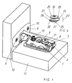
- the furniture hinge comprises a mounting plate consisting of a base plate 1 and a positioning plate 2, the base plate 1 being fastened to the side wall of the furniture box 11.
- the setting plate 2 can be detachably and releasably connected to the base plate 1.
- the hinge arm 8 is attached, which is articulated with a door-side stop part, for.
- a hinge cup 10 is connected, which is embedded in the furniture door 12 via screws 9.
- a conventional side adjustment screw 13 is provided to adjust the side of the furniture door 12.
- the depth adjustment i.e. the adjustment of the hinge arm 8 parallel to the base plate 1, is carried out by means of a depth adjustment screw 17, which has no thread as in the prior art, but is accommodated with its screw neck in an opening in the hinge arm 8 and is rotatably but not displaceably mounted there ,
- the depth adjustment screw 17 engages with its control part 23, which has an axially upper 24 and lower eccentric disk 25, in a recess 6 in the adjusting plate 2.
- the axially upper eccentric 24 lies with its angular, facet-shaped footprint 26 on one L-shaped nose 3, which nose 3 was formed in one piece from the setting plate 2, or is attached to it.
- the lower eccentric disk 25 lies with its angular, facet-shaped standing surface 27 on the inner edge of the recess 6 of the setting plate 2.
- the nose 3 and the inner edge of the recess 6 do not lie in a common plane, the nose 3 protruding from the surface of the setting plate 2 in the direction of the hinge arm 8.
- Both shelves 26 and 27 are approximately frustoconical and tapered mirror-inverted axially to the longitudinal axis of the depth adjustment screw 17, so that the upper shelf 26 tapers to the neck 31 and head 29 of the screw 17, but the lower shelf 27 is directed away from the neck 31 and head 29 tapers.
- the contact surface 3a of the nose 3 and the contact surface 7a of the edge 7 of the opening 6 of the positioning plate 2 for the interaction with the positioning surfaces 26 and 27 are suitably conical, so that favorable sliding surfaces are provided for sliding on one another and thus almost no material abrasion he follows.
- the two axes of symmetry of the eccentric discs 24, 25 and their positioning surfaces 26, 27 are arranged radially offset from one another and to the longitudinal axis of the screw 17, so that there is eccentricity in each case.
- Both eccentric disks 24, 25 are thus somewhat eccentric to the longitudinal axis of the screw 17, so that the setting surfaces 26, 27 move radially when the screw 17 is rotated by means of a tool in the opening 30, as a result of which the depth of the door 12 is adjusted.
- the stop surface 28 of the screw 17 prevents the screw 17 from being overtightened by abutment on the adjusting plate 2 in the maximum position.
- the stop surface can instead or additionally be arranged on the upper eccentric disk 24 and a further stop surface can be provided for overtightening the screw 17 in the opposite direction, so that both directions of rotation are secured.
- the screw 17 is either at least separable between the neck 31 and the eccentric washers 24, 25 so that it can be inserted into the recess in the hinge arm, or this opening is designed as an elongated hole and is somewhat longer than the diameter of the head 29 Screw 17.
- the screw 17 can be threaded there, so that the contact surface 3a of the nose 3 rests on the surface 26 and the contact surface 7a of the opening edge 7 on the surface 27, as well the underside of the nose 3 on the flat contact surface 32 formed between the eccentric discs 24, 25, as a result of which the control part 23 is easily clamped in the setting plate 2.
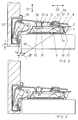
- the hinge arm 8 can be moved in the direction of the arrow 22 until the gap S has the desired value, which e.g. is preset to 2.5 mm. This enables easy and sensitive depth adjustment.
- the side adjustment screw 13 is mounted with its thread 16 in a threaded bore of the hinge arm 8 and is supported with its screw head 14 on an associated contact surface 15 of the setting plate 2.
- the hinge arm 8 can now be adjusted in the direction of the arrow 21, so that the door 12 e.g. pivoted from the position of Figure 1 into the position of Figure 2 and the gap F changes.
- the hinge arm 8 does not perform a pure lifting movement in the direction of arrow 21 during the side adjustment, but rather a pivoting movement, there is a circular movement about an imaginary axis with pivot point 19, so that the adjusting movement takes place along an arc 20 with a radius 18. This not only results in an adjustment of the joint width F, but also an undesirable change in the gap S by the amount K.
- the hinge arm 8 is thus displaced in the direction 22 by an amount K in the depth 22 by rotating the side adjustment screw 13 and pivoting the hinge arm 8 about the pivot point 19, so that the gap S changes.
- the automatic depth compensation of the depth adjustment screw 17 displaces the hinge arm 8 in the opposite direction 22 by preferably the same amount K (but negatively), so that in the most favorable case the control part 23 of the depth adjustment screw 17 compensates for the depth shift by the distance K takes place and the gap S remains constant at the preset value (eg 2.5 mm).
- the depth adjustment thus has a special depth adjustment screw 17, which is shown in more detail in FIG. 4.
- the depth adjustment screw 17 comprises two superimposed eccentric discs 24 and 25, which interact with contact surfaces arranged in the setting plate 2.
- the setting plate 2 has a special opening 6 with an opening edge 7 and one from the setting plate 2 stepped nose 3, which form contact surfaces for interaction with the upper and lower eccentric discs 24, 25.
- the essence of the invention is therefore that in the adjustment of the side adjustment screw 13, which in addition to the desired side adjustment in the direction of arrow 21 by the amount F also leads to an undesirable change in the gap width in the direction of the arrow 22 by the amount K between the door 12 and the Body 11 leads, a compensation device is used.
- the compensation device consists of two non-rotatably connected sliding surfaces 26, 27 connected to the depth adjustment screw 17, two eccentric disks 24, 25 of a control part 23, said sliding surfaces 26, 27 resting against each other on assigned, stationary surfaces 3a, 7a of the setting plate 2.
- the depth adjustment screw 17 according to the invention can already be used to set a predetermined gap dimension S, which is then changed in an undesirable manner by actuating the side adjustment screw 13. This is where the invention comes in, which provides that the connection of the depth adjustment screw 17 to the control part compensates for the undesired change in the gap width in the depth direction by the amount K when the side adjustment screw 13 is actuated.
Landscapes
- Engineering & Computer Science (AREA)
- Mechanical Engineering (AREA)
- Hinges (AREA)
Abstract
Description
- Die Erfindung betrifft ein Möbelscharnier mit einer Verstelleinrichtung für einen, mittelbar oder unmittelbar auf einer möbelseitigen ein- oder mehrteiligen Montageplatte gelagerten Scharnierarm nach dem Oberbegriff des unabhängigen Patentanspruches.
- Im allgemeinen sind bei Möbelscharnieren verschiedene Verstellmöglichkeiten vorgesehen.
- So besteht eine Verstellmöglichkeit in der Verstellung der Position des Scharnierarmes relativ zur Montageplatte in Richtung der Möbelfuge, d. h. eine Seitenverstellung der Möbeltür. Diese Verstellung wird durch die sogenannte Seitenverstellschraube erreicht, die in einem Gewinde des Scharnierarms lagert und mit ihrem Kopf in einer Aussparung der Montageplatte gehalten ist. Je nach Drehung der Schraube hebt sich der Scharnierarm mehr oder weniger von der Montageplatte ab, so dass sich damit eine seitliche Verstellung der Möbeltüre ergibt.
- Eine weitere Verstellmöglichkeit betrifft die Tiefenverstellung des Scharnierarmes, durch welche der Abstand der Möbeltür zur Stirnseite des Möbels einstellbar ist. Die Tiefenverstellung erfolgt im allgemeinen mit einer Klemmschraube, durch welche der Scharnierarm auf der Montageplatte befestigt wird. Die Klemmschraube ragt durch ein Langloch im Scharnierarm hindurch, wobei die Tiefenstellung durch Gleiten entlang des Langlochs erfolgt und der Bereich des Tiefenverstellwegs durch die Länge des Langlochs bestimmt wird.
- Ein Möbelscharnier der oben genannten Art ist z.B. aus der DE 298 11 793 U1 bekannt.
- Die bekannten Verstelleinrichtungen weisen jedoch erhebliche Nachteile auf.
- Mit Bezug auf die Seitenverstellung der Türe wird der Scharnierarm durch Verdrehen der Seitenverstellschraube um eine imaginäre Achse verschwenkt, so dass die Verstellbewegung entlang eines Kreisbogens erfolgt. Dadurch verstellt sich nicht nur die seitliche Position der Türe, sondern auch in ungewollter Weise die Tiefenposition der Türe, so dass sich der Abstand der Türe von der Stirnkante des Möbel verändert.
- Bei der Tiefeneinstellung besteht das Problem, dass die Tiefeneinstellschraube gelöst werden muss, um eine Verschiebung entlang des Langlochs zu ermöglichen. Eine feinfühlige Einstellung ist dadurch nicht möglich.
- Ein Scharnier mit Ausgleichsfunktion bei der Seitenverstellung ist in der
DE 299 14 473 U1 beschrieben. Es ist mindestens ein Schwenkhebel vorgesehen, der beim verdrehen der Seitenverstellschraube geschwenkt wird und an dem sich der Scharnierarm mittelbar oder unmittelbar abstützt, wobei der Scharnierarm beim Verdrehen der Fugenverstellschraube durch den mindestens einen Schwenkhebel parallel zur Grundplatte geführt ist. Die hier vorgestellte Konstruktion erschein jedoch sehr aufwändig in der Herstellung. Aufgabe der Erfindung ist es, ein Möbelscharnier vorzuschlagen, das über einfachere Einstellmöglichkeiten verfügt, ohne dass ein übermäßiger Konstruktions- und Herstellungsaufwand notwendig ist.
Die Lösung dieser Aufgabe erfolgt durch die Merkmale des unabhängigen Patenanspruches. - Wesentliches Merkmal ist, dass die Tiefenverstellschraube mittelbar oder unmittelbar am Scharnierarm drehbar und unverschieblich gelagert ist und ein Steuerteil mit mindestens einer Exzenterscheibe oder spiralförmigen oder wendelförmigen Scheibe mit mindestens einer mindestens teilweise kegelartigen oder konkaven oder konvexen Stellfläche aufweist, die sich an zugeordneten Anlageflächen der Montageplatte abstützt und somit ein Verdrehen der Seitenverstellschraube eine Seitenverstellung und zugleich eine Verschiebung des Scharnierarms etwa in Richtung dessen Längsachse relativ zur Montageplatte und damit eine Korrektur der Tiefenverstellung der Tür bewirkt, so dass der Spalt zwischen der Tür und der Möbelseitenwand nach erfolgter Seitenverstellung im Wesentlichen unverändert ist.
- Die Tiefeneinstellschraube ist also als Steuerteil ausgebildet, in dem sie Flächen (fassettenartige) mit geneigten Winkeln aufweist, welche zwischen zwei ortsfesten Anschlägen der Stellplatte eingespannt sind. Die Tiefeneinstellschraube ist im Scharnierarm drehbar und axial unverschiebbar gelagert.
- Vorteile:
- 1. Einfache Seiteneinstellschraube wie bei den herkömmlichen Scharnieren;
- 2. Tiefeneinstellschraube mit einer Doppelfunktion;
- 3. Nur eine einzige Schraube bewirkt die Voreinstellung des Spaltes und die Spaltkorrektur bei Seitenverstellung.
- Doppelfunktion der Tiefeneinstellschraube:
- a) Durch Drehen der Tiefeneinstellschraube wird über das Steuerteil und deren Schrägflächen die Spaltbreite voreingestellt (z.B. vorgewählte Spaltbreite 2,5 mm)
- b) Beim seitlichen Einstellen der Türe durch Verdrehen der Seiteneinstellschraube gleiten die Schrägflächen der Tiefeneinstellschrauben an den ortsfesten Anschlägen entlang und verschieben dadurch den Scharnierarm um den notwendigen Betrag zur Spaltkorrektur. Die voreingestellte Spaltbreite (in unserem Beispiel 2,5 mm) bleibt bestehen.
- Die kegelartige Stellfläche der Tiefeneinstellschraube ist bevorzugt kegelstumpfförmig ausgebildet und erstreckt sich nicht über den vollen Umfang der Tiefeneinstellschraube von 360°, sondern lediglich um z.B. 270, so dass an den offenen Stirnseiten dann Anschlagflächen zur Drehwinkelbegrenzung gebildet werden können, die mit entsprechenden Anschlagflächen an der Stellplatte zusammen wirken.
- Aber auch andere Formen außer der Kegelstumpfform der Stellflächen sind möglich, wobei lediglich mindestens eine exzentrisch drehbare Exzenterscheibe für das Gleiten der Anlagefläche der Stellplatte über den Umfang der Stellflächen als erstmalige Tiefeneinstellung nötig ist.
- Weiterhin ist an dieser Exzenterscheibe mindestens eine Schrägfläche für das radiale und gleichzeitig axiale Gleiten der Anlageflächen der Stellplatte im Bezug auf die Drehachse Tiefeneinstellschraube nötig. So kann also unter diesen Voraussetzungen auch eine Stellfläche eingesetzt werden, welche auch anstatt kegelstumpfförmig schräg, konkav oder konvex ausgebildet sein kann, oder anstatt exzentrisch, spiralförmig oder wendelförmig ausgebildet sein kann.
- Bevorzugt werden aber zwei axial übereinander liegende, in sich rotationssymmetrische Exzenterscheiben mit kegelstumpfförmigen Stellflächen eingesetzt, deren Symmetrieachsen etwa parallel beabstandet zur Drehachse der Tiefenverstellschraube und zu sich selbst verlaufen, wobei die kegelstumpfförmigen Stellflächen sich gegenläufig ausgehend von einer gemeinsamen Basis sich verjüngen.
- Die Stellplatte weist einen Durchbruch auf, in dessen Bereich die Anlageflächen für das zusammenwirkende Gleiten auf den Stellflächen der Exzenterscheiben ausgebildet sind.
- Eine erste Anlagefläche wird bevorzugt durch den Rand des Durchbruchs selbst gebildet, die zweite Anlagefläche durch eine vom Durchbruch abgesetzte Nase, wodurch die übereinanderliegenden Anlageflächen sich in zwei Ebenen für das zusammenwirkende Gleiten auf den Stellflächen der Exzenterscheiben ergeben. Hierbei ist die Nase vorteilhaft einstückig aus der Stellplatte ausgestanzt und abgekröpft, wobei die Stellplatte als separates Teil auf der Grundplatte z.B. aufgeklipst ist.
- Nachfolgend wird eine Ausführungsform der Erfindung anhand von Zeichnungsfiguren näher beschrieben. Aus den Zeichnungen und deren Beschreibung ergeben sich weitere Merkmale, Vorteile und Anwendungsmöglichkeiten der Erfindung.
- Es zeigen:
- Fig. 1:
- eine perspektivische Ansicht des erfindungsgemäßen Möbelscharniers im Montagezustand mit teilweise Längsschnitt durch den Scharnierarm;
- Fig. 2:
- einen Längsschnitt durch das erfindungsgemäße Möbelscharnier in einerersten Stellung mit maximaler Seitenverstellung;
- Fig. 3:
- einen Längsschnitt durch das erfindungsgemäße Möbelscharnier in Einer zweiten Stellung mit minimaler Seitenverstellung;
- Fig. 4:
- eine Seitenverstellschraube nach der Erfindung;
- Das Möbelscharnier umfasst eine Montageplatte, bestehend aus einer Grundplatte 1 und einer Stellplatte 2, wobei die Grundplatte 1 an der Seitenwand des Möbelkastens 11 befestigt ist. Die Stellplatte 2 kann rastend und lösbar mit der Grundplatte 1 verbunden werden. Auf der Stellplatte 2 ist der Scharnierarm 8 befestigt, welcher gelenkig mit einem türseitigen Anschlagteil, z. B. einem Scharniertopf 10, verbunden ist, der in der Möbeltüre 12 über Schrauben 9 eingelassen ist. Zur Seitenverstellung der Möbeltüre 12, d. h. zur Verstellung des Scharnierarms 8 in Richtung zur Montageebene bzw. Grundplatte 1, ist eine herkömmliche Seitenverstellschraube 13 vorgesehen.
- Die Tiefenverstellung, also die Verstellung des Scharnierarmes 8 parallel zur Grundplatte 1, erfolgt mittels einer Tiefenverstellschraube 17, welche kein Gewinde wie beim Stand der Technik aufweist, sondern mit ihrem Schraubenhals in einer Öffnung im Scharnierarm 8 aufgenommen ist und dort drehbar aber nicht verschiebbar gelagert ist. Zusätzlich dazu greift die Tiefenverstellschraube 17 mit ihrem Steuerteil 23, welche eine axial obere 24 und untere Exzenterscheibe 25 besitzt, in eine Ausnehmung 6 in der Stellplatte 2 ein. Hierbei liegt die axial obere Exzenterscheibe 24 mit ihrer winkeligen, fassettenförmigen Stellfläche 26 an einer L-förmigen Nase 3 an, welche Nase 3 einteilig aus der Stellplatte 2 gebildet wurde, oder an dieser befestigt ist. Weiterhin liegt die untere Exzenterscheibe 25 mit ihrer winkeligen, fassettenförmigen Stellfläche 27 an dem Innenrand der Ausnehmung 6 der Stellplatte 2 an. Die Nase 3 und der Innenrand der Ausnehmung 6 liegen hierbei nicht in einer gemeinsamen Ebene, wobei die Nase 3 aus der Oberfläche der Stellplatte 2 in Richtung Scharnierarm 8 ragt.
- Beide Stellflächen 26 und 27 sind etwa kegelstumpfförmig ausgebildet und axial zur Längsachse der Tiefenverstellschraube 17 spiegelverkehrt konisch zulaufend, so dass die obere Stellfläche 26 zum Hals 31 und Kopf 29 der Schraube 17 zuläuft, die untere Stellfläche 27 aber vom Hals 31 und Kopf 29 weg gerichtet zuläuft. Auch die Anlagefläche 3a der Nase 3 und die Anlagefläche 7a des Rands 7 der Öffnung 6 der Stellplatte 2 für das Zusammenwirken mit den Stellflächen 26 und 27 sind geeignet konisch ausgeführt, so dass günstige Gleitflächen für das aufeinander Gleiten bereit gestellt werden und damit nahezu kein Materialabrieb erfolgt.
- Zudem sind die beiden Symmetrieachsen der Exzenterscheiben 24, 25 und deren Stellflächen 26, 27 radial zueinander und zur Längsachse der Schraube 17 versetzt angeordnet, so dass jeweils Exzentrizität besteht. Beide Exzenterscheiben 24, 25 sind also zur Längsachse der Schraube 17 etwas exzentrisch ausgebildet, so dass die Stellflächen 26, 27 sich bei Drehen der Schraube 17 über Eingriff eines Werkzeuges in die Öffnung 30 radial bewegen, wodurch die Tiefeneinstellung der Türe 12 erfolgt.
- Die Anschlagfläche 28 der Schraube 17 verhindert ein Überdrehen der Schraube 17 durch Anlage an der Stellplatte 2 in Maximalposition. Ebenso kann die Anschlagfläche statt dessen oder zusätzlich an der oberen Exzenterscheibe 24 angeordnet sein und auch eine weitere Anschlagfläche für das Überdrehen der Schraube 17 in Gegenrichtung vorgesehen sein, so dass beide Drehrichtungen gesichert sind.
- Die Schraube 17 ist entweder mindestens zwischen dem Hals 31 und den Exzenterscheiben 24, 25 teilbar ausgebildet, so dass ein Einführen in die Ausnehmung im Scharnierarm möglich ist, oder aber diese Öffnung ist als Langloch ausgebildet und ist etwas länger als der Durchmesser des Kopfes 29 der Schraube 17.
- In einer bestimmten relativen Lage der Schraube 17 zur Öffnung 6 in der Stellplatte 2 kann die Schraube 17 dort eingefädelt werden, so dass dann die Anlagefläche 3a der Nase 3 auf der Fläche 26 und die Anlagefläche 7a des Öffnungsrands 7 auf der Fläche 27 aufliegt, sowie die Unterseite der Nase 3 auf der zwischen den Exzenterscheiben 24, 25 gebildete ebenen Auflagefläche 32, wodurch das Steuerteil 23 leicht in der Stellplatte 2 geklemmt wird.
- Wird die Tiefenverstellschraube 17 dann durch Überwinden des Klemmwiderstandes gedreht, so kann der Scharnierarm 8 in Pfeilrichtung 22 verschoben werden, bis der Spalt S den gewünschten Wert aufweist, welcher z.B. auf 2.5 mm voreingestellt wird. Somit lässt sich eine leichte und feinfühlige Tiefenverstellung erzielen.
- Die Seitenverstellschraube 13 ist mit ihrem Gewinde 16 in einer Gewindebohrung des Scharnierarmes 8 gelagert und stützt sich mit ihrem Schraubenkopf 14 auf einer zugeordneten Anlagefläche 15 der Stellplatte 2 ab. Durch Verdrehen der Seitenverstellschraube 13 lässt sich nun der Scharnierarm 8 in Pfeilrichtung 21 verstellen, so dass die Türe 12 z.B. von der Position nach Figur 1 in die Position nach Figur 2 verschwenkt und der Spalt F sich ändert.
- Da nun aber der Scharnierarm 8 bei der Seitenverstellung keine reine Abhebebewegung in Pfeilrichtung 21 ausführt, sondern eine Schwenkbewegung, erfolgt eine Kreisbewegung um eine imaginäre Achse mit Drehpunkt 19, so dass die Verstellbewegung entlang eines Kreisbogens 20 mit Radius 18 erfolgt. Dadurch ergibt sich nicht nur eine Verstellung der Fugenbreite F, sondern gleichzeitig eine unerwünschte Veränderung des Spaltes S um den Betrag K.
- Dieser unerwünschten Tiefenverstellbewegung wird erfindungsgemäß entgegengewirkt, indem die Tiefenverstellschraube 17 das Steuerteil 23 aufweisen, welche die Änderung des Spaltes S um den Betrag K bei Drehen der Seitenverstellschraube 13 kompensieren.
- Erfolgt nun eine Drehbewegung der Seitenverstellschraube 13 nach rechts, so wird aufgrund des Gewindes 16 der Scharnierarm 8 nach oben abgehoben und gleichzeitig die Stellflächen 26, 27 auf den zugeordneten Anlageflächen der Nase 3 und des Öffnungsrandes 7 der Stellplatte 2 gleiten, welche ja über die Grundplatte 1 mit dem Möbelkorpus 11 verbunden ist. Durch dieses Gleiten der Stellflächen 26, 27 auf den zugeordneten Anlageflächen der Nase 3 und des Öffnungsrandes 7 der Stellplatte 2 wird dann also automatisch bei Drehen der Seitenverstellschraube 13 und dem damit verbundenen Verschwenken des Scharnierbandes 8 und damit der Türe 12, der Spalt S um den negativen Betrag K dadurch geändert, dass Scharnierband 8 und damit die Türe 12 in Gegenrichtung 22 bewegt wird.
- Der Scharnierarm 8 wird also durch Drehen der Seitenverstellschraube 13 und Verschwenken der Scharnierarmes 8 um den Drehpunkt 19 um einen Betrag K in der Tiefe in Richtung 22 verschoben, so dass sich der Spalt S verändert. Gleichzeitig wird jedoch durch die automatische Tiefenkompensation der Tiefenverstellschraube 17 der Scharnierarm 8 in entgegen gesetzter Richtung 22 um bevorzugt den gleichen Betrag K (jedoch negativ) verschoben, so dass durch das Steuerteil 23 der Tiefenverstellschraube 17 im günstigsten Fall eine Kompensation der Tiefenverschiebung um den Berag K erfolgt und der Spalt S konstant beim voreingestellten Wert (z.B. 2,5 mm) beibehalten bleibt.
- Die Tiefenverstellung weist also eine spezielle Tiefenverstellschraube 17 auf, die in Figur 4 näher dargestellt ist. Die Tiefenverstellschraube 17 umfasst zwei übereinanderliegende Exzenterscheiben 24 und 25, die mit in der Stellplatte 2 angeordneten Anlageflächen zusammenwirken. Hierzu weist die Stellplatte 2 einen speziellen Durchbruch 6 mit Öffnungsrand 7 und eine von der Stellplatte 2 abgesetzte Nase 3 auf, welche Anlageflächen für das Zusammenwirken mit der oberen und unteren Exzenterscheibe 24, 25 bilden.
- Der Kern der Erfindung liegt also darin, dass bei der Verstellung der Seiteneinstellschraube 13, die neben der erwünschten Seitenverstellung in Pfeilrichtung 21 um den Betrag F auch zu einer unerwünschten Veränderung der Spaltbreite in Tiefenrichtung in Pfeilrichtung 22 um den Betrag K zwischen der Tür 12 und dem Korpus 11 führt, eine Kompensationseinrichtung verwendet wird. Die Kompensationseinrichtung besteht aus zwei drehfest mit der Tiefenverstellschraube 17 verbundenen schräg gegeneinander gestellten Gleitflächen 26, 27 zweier Exzenterscheiben 24, 25 eines Steuerteils 23, wobei diese gegeneinandergestellten Gleitflächen 26, 27 an zugeordneten, ortsfesten Flächen 3a, 7a der Stellplatte 2 anliegen.
- Bei Betätigung der Seiteneinstellschraube 13 wird somit das Steuerteil entlang den Gleitflächen 26, 27 in der Stellplatte 2 in Scharnierlängsrichtung verschoben und eine sich mit der Betätigung der Seiteneinstellschraube 13 ergebende Veränderung um den Betrag K des Spaltes S zwischen Tür 12 und Korpus 11 wird durch diese Kompensationsbewegung ausgeglichen.
- Vorausgesetzt wird hierbei, dass man mit der erfindungsgemäßen Tiefeneinstellschraube 17 bereits schon ein vorgegebenes Spaltmaß S einstellen kann, welches dann in unerwünschter Weise durch Betätigung der Seiteneinstellschraube 13 verändert wird. Hier setzt dann die Erfindung ein, die vorsieht, dass aufgrund der Verbindung der Tiefeneinstellschraube 17 mit dem Steuerteil es zu einer Kompensation der unerwünschten Veränderung der Spaltbreite in Tiefenrichtung um den Betrag K kommt, wenn die Seiteneinstellschraube 13 betätigt wird.
-
- 1
- Grundplatte
- 2
- Stellplatte
- 3
- Nase; 3a Anlagefläche
- 4
- Lager für 13
- 5
- Durchbruch
- 6
- Durchbruch für 17
- 7
- Rand von 6; 7a Anlagefläche
- 8
- Scharnierarm
- 9
- Schraube
- 10
- Scharniertopf
- 11
- Möbelseitenwand
- 12
- Möbeltür
- 13
- Seitenverstellschraube
- 14
- Schraubenkopf
- 15
- Anlagefläche
- 16
- Gewinde
- 17
- Tiefenverstellschraube
- 18
- Radius
- 19
- Drehpunkt
- 20
- Kreisbogen
- 21
- Pfeilrichtungen
- 22
- Pfeilrichtungen
- 23
- Steuerteil
- 24
- Obere Exzenterscheibe von 23
- 25
- Untere Exzenterscheibe von 23
- 26
- Winklige Stellfläche von 24
- 27
- Winklige Stellfläche von 25
- 28
- Anschlagfläche
- 29
- Schraubenkopf von 17
- 30
- Öffnung für Werkzeug in 29
- 31
- Hals von 17
- 32
- ebene Auflagefläche von 25
- S
- Spaltbreite in Tiefenrichtung
- K
- Kompensationsbetrag von S
- F
- Spaltbreite in Seitenrichtung
Claims (12)
- Möbelscharnier mit einer Verstelleinrichtung für einen mittelbar oder unmittelbar auf einer möbelseitigen, ein- oder mehrteiligen Montageplatte (1, 2) gelagerten Scharnierarm (8), der gelenkig mit einem türseitigen Anschlagteil (10) verbunden ist, wobei die Verstelleinrichtung eine Seitenverstellschraube (13) aufweist, mittels der die Position des Scharnierarms (8) im Wesentlichen senkrecht zur Ebene der Montageplatte (1, 2) zur Seitenverstellung der Türe (12) veränderbar ist, und eine Tiefenverstellschraube (17) aufweist, mittels der die Position des Scharnierarms (8) parallel zur Längserstreckung der Montageplatte (1, 2) zur Tiefenverstellung der Türe (12) veränderbar ist, dadurch gekennzeichnet, daß die Tiefenverstellschraube (17) mittelbar oder unmittelbar am Scharnierarm (8) drehbar und unverschieblich gelagert ist und ein Steuerteil (23) mit mindestens einer Exzenterscheibe (24, 25) oder einer spiralförmigen oder wendelförmigen Scheibe mit mindestens einer mindestens teilweise kegelartigen oder konkaven oder konvexen Stellfläche (26, 27) aufweist, die sich an zugeordneten Anlageflächen (3, 7) der Montageplatte (1, 2) abstützt und somit ein Verdrehen der Seitenverstellschraube (13) eine Seitenverstellung um einen Betrag (F) und zugleich eine Verschiebung des Scharnierarms (8) etwa in Richtung dessen Längsachse relativ zur Montageplatte (1, 2) und damit eine Korrektur der Tiefenverstellung der Tür (12) um einen Betrag (K) bewirkt, so dass eine Spaltbreite (S) zwischen der Tür (12) und der Möbelseitenwand (11) nach erfolgter Seitenverstellung im Wesentlichen unverändert ist.
- Möbelscharnier nach Anspruch 1, dadurch gekennzeichnet, daß die Montageplatte eine Grundplatte (1) und eine Stellplatte (2) umfaßt.
- Möbelscharnier nach einem der Ansprüche 1 oder 2, dadurch gekennzeichnet, daß die mindestens eine Stellfläche (26, 27) sich nicht über den vollen Umfang von 360° erstreckt.
- Möbelscharnier nach Anspruch 3, dadurch gekennzeichnet, daß die Symmetrieachse der mindestens einen Stellfläche (26, 27) etwa parallel beabstandet zur Drehachse der Tiefenverstellschraube (17) verlauft.
- Möbelscharnier nach einem der Ansprüche 1 bis 4, dadurch gekennzeichnet, daß zwei axial übereinander liegende Exzenterscheiben (24, 25) mit zueinander spiegelbildlichen, kegelstumpfförmigen Stellflächen (26, 27) vorgesehen sind.
- Möbelscharnier nach Anspruch 5, dadurch gekennzeichnet, dass mindestens beide Symmetrieachsen der Exzenterscheiben (24, 25) etwa parallel beabstandet zur Drehachse der Tiefenverstellschraube (17) und etwa parallel beabstandet gegenseitig zu sich selbst verlaufen.
- Möbelscharnier nach einem der Ansprüche 5 oder 6, dadurch gekennzeichnet, daß die axial untere, am freien Ende der Tiefenverstellschraube (17) gelegene Exzenterscheibe (25) sich zum freien Ende hin verjüngt, die am Schraubenkopf (29) gelegene obere Exzenterscheibe (24) jedoch sich in entgegengesetzter Richtung hin verjüngt.
- Möbelscharnier nach einem der Ansprüche 1 bis 7, dadurch gekennzeichnet, daß die Stellplatte (2) einen Durchbruch (6) aufweist, in dessen Bereich die Anlageflächen (3, 7) für das zusammenwirkende Gleiten auf der mindestens einen Stellfläche (26, 27) ausgebildet sind.
- Möbelscharnier nach einem der Ansprüche 1 bis 8, dadurch gekennzeichnet, daß die Stellplatte (2) am Rand (7) des Durchbruchs (6) eine erste Anlagefläche (7a) und eine vom Durchbruch abgesetzte Nase (3) mit Anlagefläche (3a) aufweist, wodurch sich in zwei Ebenen übereinanderliegende Anlageflächen (3a, 7a) für das zusammenwirkende Gleiten auf der mindestens einen Stellfläche (26, 27) ergeben.
- Möbelscharnier nach einem der Ansprüche 1 bis 9, dadurch gekennzeichnet, daß die Tiefenverstellschraube (17) Anschlagflächen (28) zur Begrenzung des Drehwinkels besitzen.
- Möbelscharnier nach Anspruch 10, dadurch gekennzeichnet, daß die Anschlagflächen (28) zur Anlage an der Stellplatte (2) dienen.
- Möbelscharnier nach einem der Ansprüche 1 bis 11, dadurch gekennzeichnet, daß die Tiefenverstellschraube (17) einen rotationssymmetrischen Hals (31) besitzt, welcher eine Ausnehmung des Scharnierarms (8) durchgreift und drehbar aber unverschieblich darin aufgenommen ist.
Applications Claiming Priority (2)
| Application Number | Priority Date | Filing Date | Title |
|---|---|---|---|
| DE10210017 | 2002-03-07 | ||
| DE10210017A DE10210017C1 (de) | 2002-03-07 | 2002-03-07 | Möbelscharnier mit Verstelleinrichtung |
Publications (3)
| Publication Number | Publication Date |
|---|---|
| EP1342874A2 true EP1342874A2 (de) | 2003-09-10 |
| EP1342874A3 EP1342874A3 (de) | 2006-03-08 |
| EP1342874B1 EP1342874B1 (de) | 2009-10-07 |
Family
ID=7714039
Family Applications (1)
| Application Number | Title | Priority Date | Filing Date |
|---|---|---|---|
| EP03004625A Expired - Lifetime EP1342874B1 (de) | 2002-03-07 | 2003-03-03 | Möbelscharnier mit Verstelleinrichtung |
Country Status (4)
| Country | Link |
|---|---|
| US (1) | US6925682B2 (de) |
| EP (1) | EP1342874B1 (de) |
| AT (1) | ATE445072T1 (de) |
| DE (2) | DE10210017C1 (de) |
Families Citing this family (13)
| Publication number | Priority date | Publication date | Assignee | Title |
|---|---|---|---|---|
| US6883204B2 (en) * | 2002-05-29 | 2005-04-26 | Arturo Salice S.P.A. | Hinge |
| DE102004041300A1 (de) * | 2004-08-25 | 2006-03-02 | Lautenschläger, Horst | Verstelleinrichtung für Möbelteile |
| AT501396B1 (de) * | 2004-10-28 | 2007-10-15 | Blum Gmbh Julius | Falttürenscharnier |
| JP5346579B2 (ja) * | 2005-04-29 | 2013-11-20 | プレメタ ゲゼルシャフト ミット ベシュレンクター ハフツング ウント コンパニー コマンディートゲゼルシャフト | ヒンジ |
| DE102006034306A1 (de) * | 2006-07-21 | 2008-01-24 | Liberty Hardware Mfg. Corp. | Möbelscharnier |
| DE202008012170U1 (de) * | 2008-04-18 | 2009-09-03 | Paul Hettich Gmbh & Co. Kg | Verstellvorrichtung für Möbel |
| US9074404B2 (en) | 2012-05-30 | 2015-07-07 | Bsh Home Applicances Corporation | Household appliance having system for aligning doors and method thereof |
| CN104879006B (zh) * | 2015-05-14 | 2017-10-17 | 陈明开 | 一种柜门铰链的改良结构 |
| US11261631B2 (en) * | 2017-05-11 | 2022-03-01 | Samet Kalip Ve Maden Esya San. Ve Tic. A.S. | Hinge having pinch protection and method for displacing securing parts of a hinge |
| TWI657184B (zh) * | 2017-06-19 | 2019-04-21 | 日商世嘉智尼工業股份有限公司 | 鉸鏈裝置 |
| AT523441B1 (de) * | 2020-01-17 | 2023-05-15 | Blum Gmbh Julius | Scharnieranordnung |
| AT526748B1 (de) * | 2022-11-21 | 2025-04-15 | Blum Gmbh Julius | Möbelbeschlag oder Baubeschlag |
| CN117722096B (zh) * | 2024-02-07 | 2024-04-19 | 广东图特精密五金科技股份有限公司 | 一种快速连接锁紧机构以及快装铰链 |
Family Cites Families (32)
| Publication number | Priority date | Publication date | Assignee | Title |
|---|---|---|---|---|
| US1336174A (en) * | 1919-09-23 | 1920-04-06 | Way John Howard | Concealed or invisible butt-hinge |
| FR2421594A1 (fr) * | 1977-06-20 | 1979-11-02 | Micro Mega Sa | Tete de contre-angle pour piece a main dentaire |
| DE3209900A1 (de) * | 1982-03-18 | 1983-09-22 | Karl Lautenschläger KG, Möbelbeschlagfabrik, 6107 Reinheim | Kreuzgelenkscharnier |
| AT379851B (de) * | 1983-03-21 | 1986-03-10 | Blum Gmbh Julius | Scharnier, insbesondere fuer moebeltueren |
| DE3448346C2 (de) * | 1983-12-30 | 1990-12-13 | Julius Blum Ges.M.B.H., Hoechst, At | |
| AT383643B (de) * | 1984-10-19 | 1987-07-27 | Blum Gmbh Julius | Scharnier |
| AT384066B (de) * | 1984-10-19 | 1987-09-25 | Blum Gmbh Julius | Scharnier |
| AT391344B (de) * | 1987-08-31 | 1990-09-25 | Blum Gmbh Julius | Scharnier |
| DE3820338A1 (de) * | 1988-06-15 | 1989-12-21 | Lautenschlaeger Kg Karl | Moebelscharnier |
| DE3841405A1 (de) * | 1988-06-29 | 1990-01-04 | Salice Arturo Spa | Scharnierarm mit einer befestigungsplatte zu dessen befestigung an einem moebelteil o. dgl. |
| DE68914595T2 (de) * | 1988-11-16 | 1994-08-25 | Franco Ferrari | Türscharnier mit Schnellkupplung. |
| DE4009125A1 (de) * | 1989-05-19 | 1991-09-26 | Salice Arturo Spa | Scharnier, vorzugsweise zur anlenkung einer tuer oder klappe an eine tragwand eines korpusteils |
| DE8907480U1 (de) * | 1989-06-20 | 1989-08-03 | Karl Lautenschlaeger Gmbh & Co Kg Moebelbeschlagfabrik, 6107 Reinheim | Montageplatte für Möbelscharniere |
| EP0460233B1 (de) * | 1989-12-25 | 1994-09-28 | Kabushiki Kaisha Murakoshi Seiko | Scharnier |
| DE3943210C1 (de) * | 1989-12-28 | 1991-06-20 | Arturo Salice S.P.A., Novedrate, Como, It | |
| JP2551740Y2 (ja) * | 1991-10-09 | 1997-10-27 | 株式会社太田製作所 | スライドヒンジ |
| DE4211722A1 (de) * | 1992-04-08 | 1993-10-14 | Lautenschlaeger Mepla Werke | Möbelscharnier |
| AT404858B (de) * | 1993-10-25 | 1999-03-25 | Lautenschlaeger Mepla Werke | Als scharniertopf ausgebildeter tür-anschlagteil für möbelscharniere |
| DE4342744A1 (de) * | 1993-12-15 | 1995-06-22 | Lautenschlaeger Mepla Werke | Möbelscharnier |
| AT1214U1 (de) * | 1995-12-18 | 1996-12-27 | Blum Gmbh Julius | Scharnier |
| IT1282620B1 (it) * | 1996-02-14 | 1998-03-31 | Franco Ferrari | Dispositivo di regolazione a camma per elementi di ferramenta per mobili ed elementi di ferramenta con esso |
| AT1787U1 (de) * | 1996-08-21 | 1997-11-25 | Blum Gmbh Julius | Scharnier für möbel |
| US5964011A (en) * | 1997-09-12 | 1999-10-12 | Newell Operating Company | Adjustable casement window hinge |
| US6061872A (en) * | 1998-03-02 | 2000-05-16 | Grass Gmbh | Cabinet hinge |
| EP0967353A1 (de) * | 1998-06-26 | 1999-12-29 | Charmag S.A. | Scharnier |
| DE29811793U1 (de) | 1998-07-02 | 1999-11-18 | Mepla-Werke Lautenschläger GmbH & Co KG, 64354 Reinheim | Möbelscharnier |
| EP0982455B1 (de) * | 1998-08-25 | 2005-01-26 | Julius Blum GmbH | Möbelscharnier |
| DE29914473U1 (de) * | 1998-08-25 | 2000-01-05 | Julius Blum Ges.m.b.H., Höchst | Scharnier |
| US6268848B1 (en) * | 1998-10-23 | 2001-07-31 | Genesis Microchip Corp. | Method and apparatus implemented in an automatic sampling phase control system for digital monitors |
| DE19920137C2 (de) * | 1999-05-03 | 2002-11-28 | Grass Gmbh Hoechst | Montageplatte für Möbelscharniere |
| DE10054238B4 (de) * | 2000-11-02 | 2005-07-21 | Grass Gmbh | Möbelscharnier |
| EP1288416B1 (de) * | 2001-08-31 | 2009-12-30 | Grass GmbH | Möbelscharnier |
-
2002
- 2002-03-07 DE DE10210017A patent/DE10210017C1/de not_active Expired - Fee Related
-
2003
- 2003-03-03 DE DE50311990T patent/DE50311990D1/de not_active Expired - Lifetime
- 2003-03-03 AT AT03004625T patent/ATE445072T1/de active
- 2003-03-03 EP EP03004625A patent/EP1342874B1/de not_active Expired - Lifetime
- 2003-03-04 US US10/379,066 patent/US6925682B2/en not_active Expired - Fee Related
Also Published As
| Publication number | Publication date |
|---|---|
| DE50311990D1 (de) | 2009-11-19 |
| ATE445072T1 (de) | 2009-10-15 |
| DE10210017C1 (de) | 2003-07-31 |
| US20040034965A1 (en) | 2004-02-26 |
| EP1342874A3 (de) | 2006-03-08 |
| EP1342874B1 (de) | 2009-10-07 |
| US6925682B2 (en) | 2005-08-09 |
Similar Documents
| Publication | Publication Date | Title |
|---|---|---|
| DE10054238B4 (de) | Möbelscharnier | |
| WO1993013723A1 (de) | Implantat zur ausrichtung und fixierung zweier knochen oder knochenteile zueinander, insbesondere spondylodese-implantat | |
| EP1342874B1 (de) | Möbelscharnier mit Verstelleinrichtung | |
| AT1214U1 (de) | Scharnier | |
| EP0413135B1 (de) | Skischuh mit einem in der Höhe verstellbaren Fussbett | |
| DE19947670B4 (de) | Drehband für Türen oder Fenster | |
| AT409288B (de) | Möbelscharnier | |
| DE10110311C2 (de) | Scharnier mit Höhenverstellschraube | |
| AT406497B (de) | Scharnier | |
| EP0702386B1 (de) | Schwenkbares Betätigungsglied für einen Sicherheitsschalter | |
| DE2949962C2 (de) | Scharnier mit Schließmechanismus | |
| EP1288415A1 (de) | Möbelscharnier | |
| EP0791713B1 (de) | Scharnier | |
| CH657038A5 (de) | Artikulator zur nachbildung der stellung und des bewegungsablaufes der zahnreihen des ober- und unterkiefers fuer die anfertigung von zahnersatz. | |
| EP1781881B1 (de) | Montageplatte zur verstellbaren halterung von möbelscharnieren am korpus von möbelstücken | |
| DE3936192C2 (de) | Fixateur zum Festlegen von Knochenstücken | |
| EP0403863A1 (de) | Möbelscharnier | |
| DE29713254U1 (de) | Drehlager für Fenster oder Türen | |
| DE29920945U1 (de) | Möbelscharnier | |
| EP1223275B1 (de) | Band für Türen oder Fenster | |
| WO1986001267A1 (fr) | Systeme a bras oscillants | |
| AT526953B1 (de) | Führungsanordnung zur Führung eines bewegbaren Möbelteils | |
| DE3431820C1 (de) | Liegemöbel | |
| DE7819147U1 (de) | Schliessvorrichtung fuer eine pendeltuer | |
| EP0574654B1 (de) | Verstellbare Ausstellvorrichtung |
Legal Events
| Date | Code | Title | Description |
|---|---|---|---|
| PUAI | Public reference made under article 153(3) epc to a published international application that has entered the european phase |
Free format text: ORIGINAL CODE: 0009012 |
|
| AK | Designated contracting states |
Kind code of ref document: A2 Designated state(s): AT BE BG CH CY CZ DE DK EE ES FI FR GB GR HU IE IT LI LU MC NL PT SE SI SK TR |
|
| AX | Request for extension of the european patent |
Extension state: AL LT LV MK RO |
|
| RIN1 | Information on inventor provided before grant (corrected) |
Inventor name: MUELLER, WOLFGANG Inventor name: ALBRECHT, MARKUS |
|
| PUAL | Search report despatched |
Free format text: ORIGINAL CODE: 0009013 |
|
| AK | Designated contracting states |
Kind code of ref document: A3 Designated state(s): AT BE BG CH CY CZ DE DK EE ES FI FR GB GR HU IE IT LI LU MC NL PT SE SI SK TR |
|
| AX | Request for extension of the european patent |
Extension state: AL LT LV MK RO |
|
| 17P | Request for examination filed |
Effective date: 20060330 |
|
| AKX | Designation fees paid |
Designated state(s): AT BE BG CH CY CZ DE DK EE ES FI FR GB GR HU IE IT LI LU MC NL PT SE SI SK TR |
|
| 17Q | First examination report despatched |
Effective date: 20081209 |
|
| GRAP | Despatch of communication of intention to grant a patent |
Free format text: ORIGINAL CODE: EPIDOSNIGR1 |
|
| GRAC | Information related to communication of intention to grant a patent modified |
Free format text: ORIGINAL CODE: EPIDOSCIGR1 |
|
| GRAS | Grant fee paid |
Free format text: ORIGINAL CODE: EPIDOSNIGR3 |
|
| GRAA | (expected) grant |
Free format text: ORIGINAL CODE: 0009210 |
|
| AK | Designated contracting states |
Kind code of ref document: B1 Designated state(s): AT BE BG CH CY CZ DE DK EE ES FI FR GB GR HU IE IT LI LU MC NL PT SE SI SK TR |
|
| REG | Reference to a national code |
Ref country code: GB Ref legal event code: FG4D Free format text: NOT ENGLISH |
|
| REG | Reference to a national code |
Ref country code: CH Ref legal event code: EP |
|
| REG | Reference to a national code |
Ref country code: IE Ref legal event code: FG4D |
|
| REF | Corresponds to: |
Ref document number: 50311990 Country of ref document: DE Date of ref document: 20091119 Kind code of ref document: P |
|
| PG25 | Lapsed in a contracting state [announced via postgrant information from national office to epo] |
Ref country code: SI Free format text: LAPSE BECAUSE OF FAILURE TO SUBMIT A TRANSLATION OF THE DESCRIPTION OR TO PAY THE FEE WITHIN THE PRESCRIBED TIME-LIMIT Effective date: 20091007 |
|
| NLV1 | Nl: lapsed or annulled due to failure to fulfill the requirements of art. 29p and 29m of the patents act | ||
| PG25 | Lapsed in a contracting state [announced via postgrant information from national office to epo] |
Ref country code: ES Free format text: LAPSE BECAUSE OF FAILURE TO SUBMIT A TRANSLATION OF THE DESCRIPTION OR TO PAY THE FEE WITHIN THE PRESCRIBED TIME-LIMIT Effective date: 20100118 Ref country code: SE Free format text: LAPSE BECAUSE OF FAILURE TO SUBMIT A TRANSLATION OF THE DESCRIPTION OR TO PAY THE FEE WITHIN THE PRESCRIBED TIME-LIMIT Effective date: 20091007 Ref country code: FI Free format text: LAPSE BECAUSE OF FAILURE TO SUBMIT A TRANSLATION OF THE DESCRIPTION OR TO PAY THE FEE WITHIN THE PRESCRIBED TIME-LIMIT Effective date: 20091007 Ref country code: PT Free format text: LAPSE BECAUSE OF FAILURE TO SUBMIT A TRANSLATION OF THE DESCRIPTION OR TO PAY THE FEE WITHIN THE PRESCRIBED TIME-LIMIT Effective date: 20100208 |
|
| REG | Reference to a national code |
Ref country code: IE Ref legal event code: FD4D |
|
| PG25 | Lapsed in a contracting state [announced via postgrant information from national office to epo] |
Ref country code: NL Free format text: LAPSE BECAUSE OF FAILURE TO SUBMIT A TRANSLATION OF THE DESCRIPTION OR TO PAY THE FEE WITHIN THE PRESCRIBED TIME-LIMIT Effective date: 20091007 Ref country code: BG Free format text: LAPSE BECAUSE OF FAILURE TO SUBMIT A TRANSLATION OF THE DESCRIPTION OR TO PAY THE FEE WITHIN THE PRESCRIBED TIME-LIMIT Effective date: 20100107 Ref country code: DK Free format text: LAPSE BECAUSE OF FAILURE TO SUBMIT A TRANSLATION OF THE DESCRIPTION OR TO PAY THE FEE WITHIN THE PRESCRIBED TIME-LIMIT Effective date: 20091007 Ref country code: IE Free format text: LAPSE BECAUSE OF FAILURE TO SUBMIT A TRANSLATION OF THE DESCRIPTION OR TO PAY THE FEE WITHIN THE PRESCRIBED TIME-LIMIT Effective date: 20091007 Ref country code: EE Free format text: LAPSE BECAUSE OF FAILURE TO SUBMIT A TRANSLATION OF THE DESCRIPTION OR TO PAY THE FEE WITHIN THE PRESCRIBED TIME-LIMIT Effective date: 20091007 |
|
| PLBE | No opposition filed within time limit |
Free format text: ORIGINAL CODE: 0009261 |
|
| STAA | Information on the status of an ep patent application or granted ep patent |
Free format text: STATUS: NO OPPOSITION FILED WITHIN TIME LIMIT |
|
| PG25 | Lapsed in a contracting state [announced via postgrant information from national office to epo] |
Ref country code: CZ Free format text: LAPSE BECAUSE OF FAILURE TO SUBMIT A TRANSLATION OF THE DESCRIPTION OR TO PAY THE FEE WITHIN THE PRESCRIBED TIME-LIMIT Effective date: 20091007 Ref country code: SK Free format text: LAPSE BECAUSE OF FAILURE TO SUBMIT A TRANSLATION OF THE DESCRIPTION OR TO PAY THE FEE WITHIN THE PRESCRIBED TIME-LIMIT Effective date: 20091007 |
|
| 26N | No opposition filed |
Effective date: 20100708 |
|
| BERE | Be: lapsed |
Owner name: GRASS GMBH Effective date: 20100331 |
|
| PG25 | Lapsed in a contracting state [announced via postgrant information from national office to epo] |
Ref country code: GR Free format text: LAPSE BECAUSE OF FAILURE TO SUBMIT A TRANSLATION OF THE DESCRIPTION OR TO PAY THE FEE WITHIN THE PRESCRIBED TIME-LIMIT Effective date: 20100108 Ref country code: MC Free format text: LAPSE BECAUSE OF NON-PAYMENT OF DUE FEES Effective date: 20100331 |
|
| REG | Reference to a national code |
Ref country code: CH Ref legal event code: PL |
|
| GBPC | Gb: european patent ceased through non-payment of renewal fee |
Effective date: 20100303 |
|
| REG | Reference to a national code |
Ref country code: FR Ref legal event code: ST Effective date: 20101130 |
|
| PG25 | Lapsed in a contracting state [announced via postgrant information from national office to epo] |
Ref country code: FR Free format text: LAPSE BECAUSE OF NON-PAYMENT OF DUE FEES Effective date: 20100331 |
|
| PG25 | Lapsed in a contracting state [announced via postgrant information from national office to epo] |
Ref country code: CH Free format text: LAPSE BECAUSE OF NON-PAYMENT OF DUE FEES Effective date: 20100331 Ref country code: BE Free format text: LAPSE BECAUSE OF NON-PAYMENT OF DUE FEES Effective date: 20100331 Ref country code: LI Free format text: LAPSE BECAUSE OF NON-PAYMENT OF DUE FEES Effective date: 20100331 |
|
| PG25 | Lapsed in a contracting state [announced via postgrant information from national office to epo] |
Ref country code: GB Free format text: LAPSE BECAUSE OF NON-PAYMENT OF DUE FEES Effective date: 20100303 |
|
| PGFP | Annual fee paid to national office [announced via postgrant information from national office to epo] |
Ref country code: DE Payment date: 20120308 Year of fee payment: 10 |
|
| PGFP | Annual fee paid to national office [announced via postgrant information from national office to epo] |
Ref country code: IT Payment date: 20120227 Year of fee payment: 10 |
|
| PG25 | Lapsed in a contracting state [announced via postgrant information from national office to epo] |
Ref country code: CY Free format text: LAPSE BECAUSE OF FAILURE TO SUBMIT A TRANSLATION OF THE DESCRIPTION OR TO PAY THE FEE WITHIN THE PRESCRIBED TIME-LIMIT Effective date: 20091007 |
|
| PG25 | Lapsed in a contracting state [announced via postgrant information from national office to epo] |
Ref country code: HU Free format text: LAPSE BECAUSE OF FAILURE TO SUBMIT A TRANSLATION OF THE DESCRIPTION OR TO PAY THE FEE WITHIN THE PRESCRIBED TIME-LIMIT Effective date: 20100408 Ref country code: LU Free format text: LAPSE BECAUSE OF NON-PAYMENT OF DUE FEES Effective date: 20100303 |
|
| PG25 | Lapsed in a contracting state [announced via postgrant information from national office to epo] |
Ref country code: TR Free format text: LAPSE BECAUSE OF FAILURE TO SUBMIT A TRANSLATION OF THE DESCRIPTION OR TO PAY THE FEE WITHIN THE PRESCRIBED TIME-LIMIT Effective date: 20091007 |
|
| PGFP | Annual fee paid to national office [announced via postgrant information from national office to epo] |
Ref country code: AT Payment date: 20120524 Year of fee payment: 10 |
|
| REG | Reference to a national code |
Ref country code: AT Ref legal event code: MM01 Ref document number: 445072 Country of ref document: AT Kind code of ref document: T Effective date: 20130303 |
|
| REG | Reference to a national code |
Ref country code: DE Ref legal event code: R119 Ref document number: 50311990 Country of ref document: DE Effective date: 20131001 |
|
| PG25 | Lapsed in a contracting state [announced via postgrant information from national office to epo] |
Ref country code: AT Free format text: LAPSE BECAUSE OF NON-PAYMENT OF DUE FEES Effective date: 20130303 Ref country code: DE Free format text: LAPSE BECAUSE OF NON-PAYMENT OF DUE FEES Effective date: 20131001 |
|
| PG25 | Lapsed in a contracting state [announced via postgrant information from national office to epo] |
Ref country code: IT Free format text: LAPSE BECAUSE OF NON-PAYMENT OF DUE FEES Effective date: 20130303 |