EP1335403B1 - Entladungslampe - Google Patents
Entladungslampe Download PDFInfo
- Publication number
- EP1335403B1 EP1335403B1 EP03000200A EP03000200A EP1335403B1 EP 1335403 B1 EP1335403 B1 EP 1335403B1 EP 03000200 A EP03000200 A EP 03000200A EP 03000200 A EP03000200 A EP 03000200A EP 1335403 B1 EP1335403 B1 EP 1335403B1
- Authority
- EP
- European Patent Office
- Prior art keywords
- discharge
- electrode
- auxiliary
- main
- lamp
- Prior art date
- Legal status (The legal status is an assumption and is not a legal conclusion. Google has not performed a legal analysis and makes no representation as to the accuracy of the status listed.)
- Expired - Lifetime
Links
- 238000007789 sealing Methods 0.000 claims description 58
- 230000004888 barrier function Effects 0.000 claims description 28
- 230000015556 catabolic process Effects 0.000 claims description 13
- 238000009413 insulation Methods 0.000 claims description 13
- 238000000034 method Methods 0.000 claims description 6
- 230000008569 process Effects 0.000 claims description 2
- 208000028659 discharge Diseases 0.000 description 449
- 239000007858 starting material Substances 0.000 description 25
- 229910052751 metal Inorganic materials 0.000 description 15
- 239000002184 metal Substances 0.000 description 15
- 230000015572 biosynthetic process Effects 0.000 description 14
- 239000004020 conductor Substances 0.000 description 14
- 238000004804 winding Methods 0.000 description 14
- 230000008901 benefit Effects 0.000 description 11
- 239000004568 cement Substances 0.000 description 8
- 239000011888 foil Substances 0.000 description 8
- 238000004519 manufacturing process Methods 0.000 description 8
- 239000000463 material Substances 0.000 description 8
- QSHDDOUJBYECFT-UHFFFAOYSA-N mercury Chemical compound [Hg] QSHDDOUJBYECFT-UHFFFAOYSA-N 0.000 description 7
- 229910052753 mercury Inorganic materials 0.000 description 7
- 230000009471 action Effects 0.000 description 6
- 239000003990 capacitor Substances 0.000 description 6
- 230000009467 reduction Effects 0.000 description 6
- VYPSYNLAJGMNEJ-UHFFFAOYSA-N Silicium dioxide Chemical compound O=[Si]=O VYPSYNLAJGMNEJ-UHFFFAOYSA-N 0.000 description 5
- XKRFYHLGVUSROY-UHFFFAOYSA-N Argon Chemical compound [Ar] XKRFYHLGVUSROY-UHFFFAOYSA-N 0.000 description 4
- 230000008878 coupling Effects 0.000 description 4
- 238000010168 coupling process Methods 0.000 description 4
- 238000005859 coupling reaction Methods 0.000 description 4
- 230000005684 electric field Effects 0.000 description 4
- 239000000203 mixture Substances 0.000 description 4
- 230000005855 radiation Effects 0.000 description 4
- 238000001816 cooling Methods 0.000 description 3
- 230000000694 effects Effects 0.000 description 3
- 239000007772 electrode material Substances 0.000 description 3
- 238000005516 engineering process Methods 0.000 description 3
- 239000007789 gas Substances 0.000 description 3
- 238000009499 grossing Methods 0.000 description 3
- 238000009434 installation Methods 0.000 description 3
- 230000001737 promoting effect Effects 0.000 description 3
- 238000003466 welding Methods 0.000 description 3
- IJGRMHOSHXDMSA-UHFFFAOYSA-N Atomic nitrogen Chemical compound N#N IJGRMHOSHXDMSA-UHFFFAOYSA-N 0.000 description 2
- OKTJSMMVPCPJKN-UHFFFAOYSA-N Carbon Chemical compound [C] OKTJSMMVPCPJKN-UHFFFAOYSA-N 0.000 description 2
- 229910052786 argon Inorganic materials 0.000 description 2
- 230000007423 decrease Effects 0.000 description 2
- 230000001419 dependent effect Effects 0.000 description 2
- 239000011521 glass Substances 0.000 description 2
- 229910052736 halogen Inorganic materials 0.000 description 2
- 150000002367 halogens Chemical class 0.000 description 2
- 239000012535 impurity Substances 0.000 description 2
- 229910001507 metal halide Inorganic materials 0.000 description 2
- 150000005309 metal halides Chemical class 0.000 description 2
- 150000001457 metallic cations Chemical class 0.000 description 2
- 239000000126 substance Substances 0.000 description 2
- WKBOTKDWSSQWDR-UHFFFAOYSA-N Bromine atom Chemical compound [Br] WKBOTKDWSSQWDR-UHFFFAOYSA-N 0.000 description 1
- 229910000599 Cr alloy Inorganic materials 0.000 description 1
- 238000009825 accumulation Methods 0.000 description 1
- 230000004397 blinking Effects 0.000 description 1
- GDTBXPJZTBHREO-UHFFFAOYSA-N bromine Substances BrBr GDTBXPJZTBHREO-UHFFFAOYSA-N 0.000 description 1
- 229910052794 bromium Inorganic materials 0.000 description 1
- 229910052799 carbon Inorganic materials 0.000 description 1
- 229910021393 carbon nanotube Inorganic materials 0.000 description 1
- 239000002041 carbon nanotube Substances 0.000 description 1
- 230000008859 change Effects 0.000 description 1
- 239000000788 chromium alloy Substances 0.000 description 1
- UPHIPHFJVNKLMR-UHFFFAOYSA-N chromium iron Chemical compound [Cr].[Fe] UPHIPHFJVNKLMR-UHFFFAOYSA-N 0.000 description 1
- 239000011248 coating agent Substances 0.000 description 1
- 238000000576 coating method Methods 0.000 description 1
- 238000007796 conventional method Methods 0.000 description 1
- 230000003247 decreasing effect Effects 0.000 description 1
- 230000003111 delayed effect Effects 0.000 description 1
- 230000004069 differentiation Effects 0.000 description 1
- 238000010891 electric arc Methods 0.000 description 1
- 229910002804 graphite Inorganic materials 0.000 description 1
- 239000010439 graphite Substances 0.000 description 1
- 230000006698 induction Effects 0.000 description 1
- DNNSSWSSYDEUBZ-OUBTZVSYSA-N krypton-85 Chemical compound [85Kr] DNNSSWSSYDEUBZ-OUBTZVSYSA-N 0.000 description 1
- 239000004973 liquid crystal related substance Substances 0.000 description 1
- 230000007257 malfunction Effects 0.000 description 1
- 238000002844 melting Methods 0.000 description 1
- 230000008018 melting Effects 0.000 description 1
- 238000002156 mixing Methods 0.000 description 1
- 229910052757 nitrogen Inorganic materials 0.000 description 1
- 230000003287 optical effect Effects 0.000 description 1
- 239000000843 powder Substances 0.000 description 1
- 239000000941 radioactive substance Substances 0.000 description 1
- 230000001105 regulatory effect Effects 0.000 description 1
- 239000003566 sealing material Substances 0.000 description 1
- 238000001228 spectrum Methods 0.000 description 1
- 238000002834 transmittance Methods 0.000 description 1
- WFKWXMTUELFFGS-UHFFFAOYSA-N tungsten Chemical compound [W] WFKWXMTUELFFGS-UHFFFAOYSA-N 0.000 description 1
- 229910052721 tungsten Inorganic materials 0.000 description 1
- 239000010937 tungsten Substances 0.000 description 1
Images


Classifications
-
- H—ELECTRICITY
- H01—ELECTRIC ELEMENTS
- H01J—ELECTRIC DISCHARGE TUBES OR DISCHARGE LAMPS
- H01J61/00—Gas-discharge or vapour-discharge lamps
- H01J61/02—Details
- H01J61/54—Igniting arrangements, e.g. promoting ionisation for starting
- H01J61/547—Igniting arrangements, e.g. promoting ionisation for starting using an auxiliary electrode outside the vessel
Definitions
- the invention relates to a discharge lamp with high radiance (HID lamp), such as a high pressure mercury discharge lamp, a metal halide lamp or the like, which is used for example as a light source for a projector.
- HID lamp high radiance
- a high pressure mercury discharge lamp such as a high pressure mercury discharge lamp, a metal halide lamp or the like, which is used for example as a light source for a projector.
- a discharge lamp with high radiance such as a high pressure mercury discharge lamp, a metal halide lamp, or the like is used.
- these discharge lamps it is generally necessary when starting to apply a high voltage between the main discharge electrodes or between the electrode for the main discharge and the inside of the discharge vessel, to produce an insulation breakdown in the discharge medium within the discharge vessel, and to induce a glow discharge or an arc discharge, the electrons of the plasma which has been produced thereby acting as the triggering substance.
- the voltage which is necessary for the insulation breakdown during starting is generally roughly a few kilovolts when the discharge lamp is in the temperature state of roughly room temperature.
- the voltage which is necessary for the insulation breakdown during starting however changes depending on the running time after turning off following completion of prior operation, i.e. depending on the temperature of the discharge space. It can be imagined that the reason for formation of one such change is the following:
- part of the vaporized discharge medium such as mercury, halogen or the like, condenses. This gradually changes the composition of the gas portion of the discharge space. For this or similar reasons the voltage which is necessary for the insulation breakdown changes.
- the voltage which is necessary for the insulation breakdown is very low for example in the case of a discharge lamp with a discharge medium which comprises halogens such as bromine and mercury and the like, and a rare gas such as argon or the like, and which contains for example greater than or equal to 0.15 mg mercury per cubic millimeter volume of the discharge space, because there is residual plasma immediately after turning off the discharge lamp. Afterwards it does rise quickly until however shortly afterwards it begins to drop again (under the condition of natural cooling without compressed air cooling of the discharge lamp) until it reaches the minimum value after roughly 30 seconds.
- the insulation breakdown voltage repeatedly rises and falls however afterwards in a complicated manner during the interval during which the temperature of the discharge space finally drops to roughly 100 °C, i.e. for the duration of a few minutes after turning off.
- this is often called the outside trigger method which is used mainly for blinking lamps, in which without applying a high voltage between the main discharge electrodes a high voltage is applied to the conductor adjacent to the discharge vessel and in which thus a discharge is begun.
- the outside trigger method for a discharge lamp with high radiance is proposed. The purpose here is, however, not to improve the starting property.
- U.S. Patent No. 4,987,344 proposed a discharge lamp in which there is an auxiliary UV light source with an auxiliary discharge vessel which has a pair of inner electrodes.
- U.S. Patent No. 4,721,888 a discharge lamp is schematically shown in which in the vicinity of its hermetically sealed area there is an auxiliary UV light source with a pair of inner electrodes.
- U.S. Patent Nos. 5,550,421 ; 5,811,933 ; 4,818,915 (corresponding to JP HEI 1-134848 ); and 5,990,599 (corresponding to JP 2001- 512622 A ) and the like have proposed a discharge lamp in which there is an auxiliary UV light source in which in an auxiliary discharge vessel which is provided with an inner electrode a high voltage is subject to electrostatic capacitance coupling.
- U.S. Patent No. 4,812,714 (corresponding to JP HEI 1-134849 ) have proposed a discharge lamp in which there is an auxiliary UV light source in which in an auxiliary discharge vessel without an inner electrode a high voltage is subjected to electrostatic capacitance coupling.
- U.S. Patent No. 5,323,091 and International Patent Application publication WO-A-00/77826 proposed arranging a bubble-like secondary discharge chamber such that it is in contact with the conductive foil of the hermetically sealed area of the discharge lamp and which then operated as an auxiliary UV light source.
- U.S. Patent Nos. 5,959,404 (corresponding to JP HEI 8-236080 ) proposed a discharge lamp in which an auxiliary UV light source is formed integrally with the outside of its hermetically sealed area.
- U.S. Patent Nos. 6,268,698 (corresponding to JP 2000-173549 A ) proposed a discharge lamp in which an auxiliary UV light source is formed integrally with the end face of its hermetically sealed area and carries out the discharge in the open space.
- the degree of technical difficulty may be lower than in the fourth conventional example.
- the aspects that the production takes much time and that the probability of a fault-free discharge lamp is reduced are however likewise present. There is, therefore, the disadvantage that costs increase.
- the discharge is carried out in an open space with a high pressure. Therefore, it is assumed that high precision in the dimensioning of the arrangement and the like is required to produce an effective discharge stably and moreover with high efficiency.
- the primary object of the present invention is to eliminate the following through an implementation of a discharge lamp which has an auxiliary light source which is used to produce light with a short wavelength, such as UV radiation or the like, to promote ionization of the discharge medium and to reduce the absolute value of the high voltage which is to be applied during starting. This will remove the disadvantages:
- a discharge lamp (Ld) in which within the main discharge vessel (Bd) in a discharge space (Zd) for the main discharge which is filled with a discharge medium for the main discharge, there is a pair of opposite electrodes (E1, E2) for the main discharge, and there is a first electrode sealing part and a second electrode sealing part (S1, S2) for connecting the main discharge electrodes (E1, E2).
- This embodiment further includes a starting electrode (Et), in addition to the main discharge electrodes, which is arranged such that it does not come into contact with the discharge space (Zd) for the main discharge but is located at a position for assisting the main discharge, an auxiliary light source (Lx) which comprises an auxiliary discharge vessel (Bx) which is located adjacent to one side of at least one of the electrode sealing parts (S1, S2) and is not made integral with the electrode sealing parts (S1, S2) and is filled with a discharge medium for the auxiliary discharge, and a first outer electrode (Eu) in the auxiliary light source (Lx) on the outside of the auxiliary discharge vessel (Bx).
- a starting electrode Et
- an auxiliary light source which comprises an auxiliary discharge vessel (Bx) which is located adjacent to one side of at least one of the electrode sealing parts (S1, S2) and is not made integral with the electrode sealing parts (S1, S2) and is filled with a discharge medium for the auxiliary discharge
- the starting electrode (Et) and the first outer electrode (Eu) are electrically connected to one another.
- the auxiliary light source (Lx) is on the outside of the auxiliary discharge vessel (Bx) and there is a second outer electrode (Ev).
- This second outer electrode (Ev) and the main discharge electrode are electrically connected to one another on the side on which the auxiliary light source (Lx) is located.
- Another embodiment of the invention includes a first outer electrode (Eu) that is formed by both the electrode sealing part on which the auxiliary discharge vessel (Bx) is located and also the auxiliary discharge vessel (Bx) being wound with a conductive wire.
- the main discharge electrode is positioned on the side of the discharge vessel on which the auxiliary light source (Lx) is not located, and the starting electrodes (Et) are electrically connected to one another.
- the main discharge vessel (Bd) and the electrode sealing parts (S1, S2) have an essentially symmetrical arrangement with respect to the middle axis (Ax) and that the distance (RLx) between the auxiliary discharge vessel (Bx) and the middle axis (Ax) does not exceed the radius (RBd) at the thickest part (Pmax) of the outside shape of the main discharge vessel (Bd).
- said position of the starting Electrode is in the vicinity of boundary areas between the main discharge vessel (Bd) and the electrode sealing parts (S1, S2).
- a high no-load voltage is applied between the electrodes (E1, E2) for the main discharge, and at the same time, a high voltage is also applied by the starting electrode (Et) between the inside of the main discharge vessel (Bd) and an anode (E2) of the electrodes for the main discharge, by which a dielectric barrier discharge is formed, ionization of the discharge medium is promoted and an insulation breakdown induced between the electrodes (E1, E2) for the main discharge.
- Figures 1(a) & 1(b) each show, in a simplified representation, a schematic of the arrangement of the main part of the discharge lamp (Ld0) of the invention, Figure 1(a) being an outside view and Figure 1(b) being a cross section;
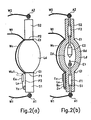
- Figures 2(a) & 2(b) each show, in a simplified representation, a schematic of one example of the arrangement of a discharge lamp (Ld) of the outside trigger type of the invention, Figure 2(a) showing the outside view and Figure 2(b) showing the cross section;
- Ld discharge lamp
- Figures 3(a) and 3(b) each show, in a simplified representation, a schematic of another example of the arrangement of a discharge lamp (Ld) of the outside trigger type of the invention, Figure 3(a) showing the outside view and Figure 3(b) showing the cross section;
- Ld discharge lamp
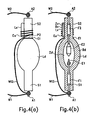
- Figures 4(a) & 4(b) each show, in a simplified representation, a schematic of one example of the arrangement of a discharge lamp (Ld) of the inside trigger type of the invention, Figure 4(a) showing the outside view and Figure 4(b) showing the cross section;
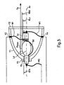
- FIG. 5 shows, in a simplified representation, a schematic of one example of the arrangement of a discharge lamp (Ld) of the invention, where it is located in a reflector (Y1), shown in simplified form;
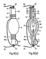
- Figures 6(a) & 6(b) each show, in a simplified representation, another schematic of one example of the arrangement of a discharge lamp (Ld) of the inside trigger type of the invention, Figure 6(a) showing the outside view and Figure 6(b) showing the cross section;
- Ld discharge lamp
- Figure 7 shows, in a simplified representation, a schematic of an example of the operating situation of a discharge lamp of the outside trigger type of the invention using a feed device of the direct current operating type;
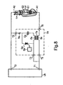
- Figure 8 shows, in a simplified representation, a schematic of another example of the operating situation of a discharge lamp of the inside trigger type of the invention using a feed device of the direct current operating type;
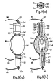
- Figures 9(a) to 9(c) each show, in a simplified representation, a schematic of another example of the arrangement of a discharge lamp (Ld) of the outside trigger type of the invention, Figure 9(a) showing the outside view, Figure 9(b) showing the cross section and Figure 9(c) showing a cross section through a surface which is perpendicular to the electrode axis;
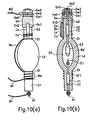
- Figures 10(a) to 10(b) each show, in a simplified representation, a schematic of still another example of the arrangement of a discharge lamp (Ld) of the outside trigger type of the invention, Figure 10(a) showing the outside view, and Figure 10(b) showing the cross section perpendicular to the page of the drawing as shown in Figure 10(a) ;
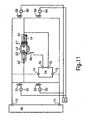
- Figure 11 shows, in a simplified representation, a schematic of one example of the operating situation of a discharge lamp of the outside trigger type of the invention using a feed device of the alternating current operating type;
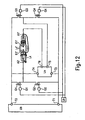
- Figure 12 shows, in a simplified representation, a schematic of another example of the operating situation of a discharge lamp of the inside trigger type of the invention using a feed device of the direct current operating type.
- Figures 1(a) & 1(b) show the embodiment of a lamp for direct current operation.
- one electrode (E1) is the cathode and the other electrode (E2) is the anode.
- the discharge space (Zd) for the main discharge which is surrounded by the main discharge vessel (Bd) which comprises silica glass or the like, is filled with a discharge medium for the main discharge.
- the electrode sealing parts (S1, S2) which are made integral with the main discharge vessel (Bd) and which also comprise silica glass or the like, there are metal foils (F1, F2) and outer leads (A1, A2) which are used for electrical connection to the electrodes (E1, E2) from outside the main discharge-discharge space (Zd) and for hermetic sealing.
- the electrode (E1), the metal foil (F1) and the outer lead (A1) are electrically connected to one another by spot welding or the like.
- the electrode (E2), the metal foil (F2) and the outer lead (A2) are electrically connected to one another by spot welding or the like.
- Conductive wires (W1, W2) for electrical connection of the outer leads (A1, A2) to a feed device are connected to the outer leads (A1, A2) likewise by spot welding or the like.
- Figures 1(a) and 1(b) show a case in which the electrodes (E1, E2) are located on an axis and in which the main discharge vessel (Bd) and the electrode sealing parts (S1, S2) are also arranged essentially symmetrically with respect to this axis.
- Figures 2(a) & 2(b) each show one example of the arrangement of the discharge lamp (Ld) of the outside trigger type according to the invention in a simplified representation.
- Figure 2(a) is an outside view.
- Figure 2(b) is a cross section.
- This discharge lamp (Ld) is arranged with respect to the main part of the discharge lamp (Ld0) such that the starting electrodes (Et) which are present in addition to the main discharge electrodes do not come into contact with the discharge space (Zd) for the main discharge. Furthermore, on one side of the electrode sealing part (S1) there is an auxiliary light source (Lx) which comprises a auxiliary discharge vessel (Bx) which is filled with a discharge medium for an auxiliary discharge.
- the above described starting electrodes (Et) are located on the cathode side in the vicinity (P1) of the boundary area between the main discharge vessel (Bd) and the electrode sealing part (S1) and in the vicinity (P2) of the boundary area between the main discharge vessel (Bd) and the electrode sealing part (S2) on the anode side.
- these two starting electrodes are electrically connected to one another by a conductive wire (Wc). If the conductive wire (Wc) is adjacent to the main discharge vessel (Bd), it also acts as a starting electrode. In steady-state operation of the discharge lamp (Ld), the main discharge vessel (Bd) and the electrode sealing part (S1, S2) reach a high temperature. It is, therefore, desirable for the starting electrodes (Et) and the conductive wire (Wc) which are adjacent to them to be formed using a highly heat-resistant metal such as tungsten, an iron-chromium alloy or the like.
- a conductive wire (Wt) is connected; it is used for its electrical connection to the feed device.
- the starting electrodes (Et) can also be formed by the main part of the discharge lamp (Ld0) being wound with a conductive wire.
- a high voltage generating part of the feed device which comprises a high voltage transformer or the like is connected such that between the conductive wire (Wt) and for example the outer lead (A1) on the cathode side a high voltage is applied.
- the high voltage generating part of the feed device which comprises a high voltage transformer or the like, is connected such that a high voltage is applied between the first outer electrode (Eu) and for example the outer lead (A1) of the cathode side.
- the material which produces light (normally UV radiation) with a wavelength which is suitable for ionization of the main discharge medium, which has been added to the discharge space (Zd) for the main discharge of the main discharge vessel (Bd) is added to the auxiliary discharge space (Zx) of the auxiliary discharge vessel (Bx) the light emitted when the dielectric barrier discharge forms in the auxiliary discharge space (Zx) propagates in the electrode sealing part (S1), travels to the discharge space (Zd) for the main discharge and ionizes the discharge medium for the main discharge which was added to the discharge space (Zd) for the main discharge, by which the formation of the dielectric barrier discharge between the inside of the main discharge vessel (Bd) and the cathode (E1) or the anode (E2) is promoted and by which at the same time the formation of a discharge in the gap between the electrodes (E1, E2) for the main discharge is promoted. Therefore, the start of the main discharge can be effectively induced and as a result the absolute value of the high voltage which is to
- auxiliary discharge space (Zx) for the following reason has a far lower temperature than the discharge space (Zd) for the main discharge:
- the cooling rate of the auxiliary discharge space (Zx) after the discharge lamp (Ld) is turned off is far higher than that of the discharge space (Zd) for the main discharge because during operation of the discharge lamp (Ld) in the auxiliary discharge space (Zx) no discharge takes place and because the auxiliary discharge vessel (Bx) is not made integral with the electrode sealing parts (S1, S2) and the main discharge vessel (Bd).
- composition of the discharge medium which is to be added to the auxiliary discharge vessel (Bx), i.e., the mixing ratio, the filling pressure and the like of the added substance, regardless of that of the discharge medium which has been added to the main discharge vessel (Bd), can be regulated.
- the non-integral inclusion of the auxiliary discharge vessel (Bx) with the electrode sealing parts (S1, S2) means that the auxiliary discharge vessel (Bx) is not installed in the electrode sealing parts (S1, S2) or that the auxiliary discharge vessel (Bx) is fused integrally to the electrode sealing parts (S1, S2) by melting when, for example, the auxiliary discharge vessel (Bx) and the electrode sealing parts (S1, S2) comprise a glass material, such as silica glass or the like.
- the auxiliary discharge vessel (Bx) is installed on the electrode sealing parts (S1, S2) it can be held by winding for example with a wire or a metal strip or can be cemented and attached for example with cement or the like.
- the discharge medium which is added to the auxiliary discharge vessel (Bx) can therefore be a gas which emits UV radiation, such as argon, nitrogen or the like. If mercury is added to the main discharge vessel (Bd), light is easily produced with a spectrum which is effective for ionization in the discharge space for the main discharge. It is, therefore, effective to also add a small amount of mercury to the auxiliary discharge vessel (Bx).
- a suitable value can be chosen from a range of 5 hPa to 100 hPa.
- the result is that a lower voltage the dielectric barrier discharge can be produced:
- the discharge vessel is filled with a conductive body, for example powder or a thin wire, such as of metal, graphite, carbon nanotube or the like, in a small amount.
- a conductive body for example powder or a thin wire, such as of metal, graphite, carbon nanotube or the like.
- a material for the auxiliary discharge vessel (Bx) of course a material should be chosen which has high transmittance with respect to light with that wavelength which is suitable for ionization of the discharge medium for the main discharge which has been produced in the auxiliary discharge space (Zx) and which furthermore withstands the high temperature in steady-state operation in the discharge space (Zd) for the main discharge.
- silica glass is suited as that material.
- the discharge lamp (Ld) When the discharge lamp (Ld) is started, it is necessary to apply the high voltage both to the first outer electrode (Eu) and also to the starting electrode (Et).
- the light from the auxiliary light source (Lx) due to ionization of the discharge medium for the main discharge not only has the action of promoting the formation of the discharge in the gap between the electrodes (E1, E2) for the main discharge, but also the action of promoting the formation of the dielectric barrier discharge between the inside of the main discharge vessel (Bd) and the cathode (E1) or the anode (E2), it is desirable to apply high voltage to the first outer electrode (Eu) earlier than the starting electrode (Et).
- auxiliary discharge vessel (Bx) For attaching the auxiliary discharge vessel (Bx) on the side of the electrode sealing part (S1), as is shown in Figures 2(a) & 2(b) , in the part of the auxiliary discharge vessel (Bx) which is farthest away from the main discharge vessel (Bd) and which reaches a high temperature during steady-state operation, there is an attachment part (Yx) of cement or the like.
- the discharge lamp of the invention by using an extension part of the conductive wire comprising the starting electrode (Et), or by similar measures, the line for applying the high voltage to the auxiliary light source (Lx) can be easily installed. Furthermore, the attachment of the auxiliary light source (Lx) in the main part of the discharge lamp (Ld0) can also be easily carried out. Therefore, the discharge lamp of the invention can be implemented with low costs because material costs can be saved and because installation is simple.
- the electrodes (E1, E2) for the main discharge the metal foils (F1, F2), the outer leads (A1, A2), the main discharge vessel (Bd) and the electrode sealing parts (S1, S2) can be arranged in the conventional manner, there is the major advantage that by the use of the auxiliary light source (Lx) of the invention, the quality of the main part of the discharge lamp (Ld0) or the reliability of the finished part or similar factors can be prevented from decreasing.
- the starting electrode (Et) in the discharge lamp to ensure that it does not come into contact with the discharge space (Zd) for the main discharge, can be arranged such that:
- the following optional methods can be used so that on the outside of the auxiliary discharge vessel (Bx) there is a conductive body:
- Figures 3(a) & 3(b) each show another example of the arrangement of a discharge lamp (Ld) of the outside trigger type of the invention in a simplified representation.
- Figure 3(a) is an outside view
- Figure 3(b) is a cross section.
- the thickness of the dielectric between the second outer electrode (Ev) and the auxiliary discharge space (Zx) is essentially identical to the thickness of the auxiliary discharge vessel (Bx). Since the thickness of the dielectric is reduced more than in the cases shown in Figures 2(a) and (b) , the advantages are the following:
- the first outer electrode (Eu) is formed by both the electrode sealing part (S1) on which the auxiliary discharge vessel (Bx) is located and also the auxiliary discharge vessel (Bx) being wound with a conductive wire using the extension part of the conductive wire comprising the starting electrode (Et).
- the outer electrode of the auxiliary light source (Lx) can be formed by a simple arrangement and electrical connection can be done with certainty.
- it can also function as an attachment means for the auxiliary light source (Lx); this is advantageous with respect to the cost reduction.
- an attachment part (Yx) of cement or the like which is shown in Figures 2(a) & 2(b) can also be used.
- the second outer electrode (Ev) is formed by the end of the auxiliary discharge vessel (Bx) being wound with a conductive wire which is connected to the outer lead (A1) on the cathode side.
- the outer electrode can be formed by a simple arrangement and electrical connection can be carried out with certainty. Moreover it can also act as an attachment means for the auxiliary light source (Lx); this is advantageous with respect to cost reduction.
- the conductive wire which is wound as the second outer electrode (Ev) around the auxiliary discharge vessel (Bx) can also be implemented by lengthening the conductive wire (W1) which is connected to the outer lead (A1).
- the second outer electrode (Ev) is of course an outer electrode and by electrostatic coupling induces a dielectric barrier discharge in the auxiliary discharge space (Zx). Cement or the like can be applied to the part in which the conductive wire is wound as the second outer electrode (Ev) around the auxiliary discharge vessel (Bx) for its stable attachment.
- the second outer electrode (Ev) can, moreover, also be formed around the auxiliary discharge vessel (Bx) for example by application of a conductive paste.
- the connection of the outer lead (A1) to the second outer electrode (Ev) can, furthermore, be accomplished by, for example, a conductive paste being applied to one end (SP1) of the electrode sealing part (S1) so that the second outer electrode (Ev) and the outer lead (A1) are also electrically connected to one another. Because it also acts as the attachment of the auxiliary discharge vessel (Bx), the arrangement can also be simplified, the working sequences for processing can be reduced and thus also the costs reduced.
- Figures 4(a) & 4(b) each show an example of a discharge vessel (Ld) of the inner trigger type of the invention, in which the lamp is started by applying a high voltage between the electrodes (E1, E2) for the main discharge.
- Figure 4(a) is an outside view.
- Figure 4(b) is a cross section.
- This discharge lamp is arranged with respect to the main part of the discharge lamp (Ld0) such that the starting electrode (Et) which is present in addition to the main discharge electrodes does not come into contact with the discharge space (Zd) for the main discharge.
- the auxiliary light source (Lx) which includes an auxiliary discharge vessel (Bx) which is filled with the discharge medium for the auxiliary discharge, is located on one side of the electrode sealing part (S2) on the anode side.
- the starting electrode (Et) and the outer lead (A1) are electrically connected to one another on the cathode side which is connected to the electrode on the side which is opposite the side on which the auxiliary light source (Lx) is located, by means of a conductive wire (Wt2).
- the conductive wire (Wt) is no longer needed for the connection to the high voltage generating part which is located in the discharge lamp shown in Figures 2(a) & 2(b) . This is advantageous when the number of cables for electrical connection of the discharge lamp to the feed device is to be reduced.
- the starting electrode (Et) is formed by a conductive wire being wound around the main part of the discharge lamp (Ld0) in the vicinity (P2) of the boundary area to the electrode sealing part (S2) on the anode side.
- the first outer electrode (Eu) of the auxiliary light source (Lx) is formed around both the electrode sealing part (S2) on which the auxiliary discharge vessel (Bx) is located and also the auxiliary discharge vessel (Bx) with a conductive wire formed as an extension part of the conductive wire comprising the starting electrode (Et).
- the conductor which forms the anode (E2), the metal foil (F2) and the outer lead (A2) and which is present within the area of the electrode sealing part (S2) to which the auxiliary discharge vessel (Bx) is adjacent is formed integrally with one another and to the second outer electrode between which and the first outer electrode (Eu) a high voltage is applied.
- a dielectric barrier discharge is formed in the auxiliary discharge space (Zx) in the auxiliary discharge vessel (Bx).
- the light emitted in this way from the auxiliary light source (Lx) due to ionization of the discharge medium for the main discharge also promotes the formation of a dielectric barrier discharge between the inside of the main discharge vessel (Bd) and the anode (E2), at the same time promotes the formation of a discharge in the gap between the electrodes (E1, E2) for the main discharge and as a result thereof can reduce the absolute value of the high voltage which is to be applied to the conductive wire (Wt).
- FIG. 5 shows another arrangement of a discharge lamp (Ld) of the invention in which a structure is shown in which it is installed in a reflector (Y1) which has a reflection surface for example in the shape of a paraboloid of revolution and which is used for emergence of the emission of the discharge lamp (Ld) in a certain direction.
- Y1 which has a reflection surface for example in the shape of a paraboloid of revolution and which is used for emergence of the emission of the discharge lamp (Ld) in a certain direction.
- the reflection surface of the reflector (Y1) has a reflection surface in the shape of a paraboloid of revolution
- the light ray pencil which has been reflected by the reflector (Y1) the light ray (Ya) tries to pass through the vicinity of the main discharge vessel (Bd) is not exactly parallel, but essentially parallel to the middle axis (Ax).
- the auxiliary light source (Lx) there is therefore no disadvantage.
- Figure 5 shows, also by way of example, a state in which there is a light exit window (Y2) which jackets the front of the reflector (Y1) and in which the discharge lamp (Ld) and the reflector (Y1) are attached in a lamp attachment opening (Yh) by the arrangement of an attachment part (Y5) of cement or the like. Furthermore, it is shown here, by way of example, that the conductive wire (Wt) to which the starting electrode (Et) and the first outer electrode (Eu) of the auxiliary light source (Lx) are connected is made electrically connectable to the outer part of the reflector (Y1), for example via an eye (Y3).
- the side on which the auxiliary light source (Lx) is located is the electrode sealing part (S1) on the cathode side and in which the conductive wire (W1) can be electrically connected to the outer part of the reflector (Y1) for example via an eye (Y4).
- the side on which the auxiliary light source (Lx) is located is the electrode sealing part (S2) on the anode side.
- Figure 5 shows the state in which in the electrode sealing part on the side which is opposite the side on which the auxiliary light source (Lx) is located, the discharge lamp (Ld) and the reflector (Y1) are attached to one another.
- the discharge lamp (Ld) and the reflector (Y1) can also be attached to one another in the electrode sealing part on the side on which the auxiliary light source (Lx) is located.
- the ratio of the dimensions of the auxiliary light source (Lx) taken exactly should be fixed such that the distance (RLx) between the part of the auxiliary discharge vessel (Bx) which is farthest away from the middle axis (Ax) and the middle axis (Ax) does not exceed the radius (RYh) of the lamp attachment opening (Yh).
- the discharge lamp (Ld) in this case by the following measures with the dimensional ratio of the auxiliary light source (Lx):
- Figures 6(a) & 6(b) each show an example of the arrangement of a discharge lamp (Ld) of the inside trigger type of the invention.
- Figure 6(a) shows the outside view and
- Figure 6(b) shows the cross section.
- the auxiliary light source (Lx) is located on the electrode sealing part (S2) on the anode side.
- a second outer electrode (Ev) is actively located adjacent to the auxiliary discharge vessel (Bx) and is electrically connected to the outer lead (A1) which belongs to the electrode sealing part (S2) on the side on which the auxiliary light source (Lx) is located. Therefore the following advantages arise:
- a coil-like conductive wire (We) is wound in such a way that it surrounds the hermetically sealed area (SF1) on the cathode side of the electrode sealing part (S1) of the anode side. It is connected to the outer lead (A1) of the cathode side via a conductive wire (We1).
- a conductive body which is arranged such that it surrounds the hermetically sealed area (SF1) on the cathode side, like the conductive wire (We), and in which during the interval during which essentially the main discharge of the discharge lamp forms, a state with the same electrical potential as the outer lead (A1) is maintained on the cathode side, is called a "cathode conductor with the same electrical potential" in these application documents.
- the metallic cations of the impurities which are contained in the hermetic sealing material as is described in Japanese patent HEI 4-40828 , in the hermetically sealed area (SF1) on the cathode side of the lamp which in the operating state has reached a high temperature, are driven in the direction in which they move away from the electrode material comprising the cathode.
- SF1 hermetically sealed area
- Figure 7 shows in a simplified representation an example of the discharge lamp of the outside trigger type of the invention operated using a feed device of the direct current operating type.
- Figure 7 shows an example of the discharge lamp (Ld) in which the lamp described above using Figures 3(a) & 3(b) is connected.
- the reference letters (Ub) label a feed circuit to which a direct current source (Ua), such as a PFC (power factor corrector) or the like, is connected as the power source.
- Ua direct current source
- the outer leads (A1, A2) of the discharge lamp (Ld) are connected to the output terminals (T1, T2) of the feed circuit (Ub).
- a feed circuit of the voltage reduction chopper type is shown by way of example as the feed circuit (Ub).
- a switching device such as a FET or the like
- the current from the direct current source (Ua) is turned on or off. If the switching device (Qb) is in the ON state, the direct current source (Ua) via a choke (Lb) charges a smoothing capacitor (Cb) and current is supplied to the discharge lamp (Ld).
- the switching device (Qb) is in the OFF state, by the induction action of the choke (Lb) the smoothing capacitor (Cb) is charged via the diode (Db) and current is supplied to the discharge lamp (Ld).
- a gate signal with a suitable pulse duty factor from the gate driver circuit (Gb) is delivered to the switching device (Qb) such that the discharge current which is flowing between the electrodes (E1, E2) for the main discharge of the lamp (Ld), the voltage between the electrodes (E1, E2) for the main discharge or the lamp wattage as a product of this current and this voltage has a suitable value which corresponds to the state of the discharge lamp (Ld) at this time.
- the lamp voltage or the lamp wattage there is a resistor divider or shunt resistor for determining the voltage of the smoothing capacitor (Cb) and the current supplied to the discharge lamp (Ld). Furthermore, normally there is a control circuit which makes it possible for the gate driver circuit (Gb) to produce a suitable gate signal. They are however not shown in Figure 7 .
- a gate driver circuit (Ge) By closing a switching device Qe such as a SCR thyristor or the like, by a gate driver circuit (Ge) with suitable timing the charging voltage of the capacitor (Ce) is applied to the primary winding (Pe) of a high voltage transformer (Te).
- a gate driver circuit (Ge) With suitable timing the charging voltage of the capacitor (Ce) is applied to the primary winding (Pe) of a high voltage transformer (Te).
- the secondary winding (Se) of the high voltage transformer (Te) therefore an increased voltage which corresponds to the arrangement of the high voltage transformer (Te) is formed.
- the voltage which has been applied to the primary winding (Pe) quickly decreases according to the discharge of the capacitor (Ce).
- the voltage which forms in the secondary winding (Se) therefore becomes a pulse.
- One end of the secondary winding (Se) of the high voltage transformer (Te) is connected via the output terminal (T5) of the starter (Ue) to one of the electrodes of the discharge lamp (Ld), specifically to one electrode (the cathode in this case), and the second outer electrode (Ev) of the auxiliary light source (Lx).
- the other end of the secondary winding (Se) of the high voltage transformer (Te) is connected via the output terminal (T6) of the starter (Ue) to the starting electrode (Et) which is located outside the main discharge vessel (Bd) of the discharge lamp (Ld) and to the first outer electrode (Eu) of the auxiliary light source (Lx).
- a dielectric barrier discharge is produced. Furthermore, between the electrodes (E1, E2) for the main discharge of the discharge lamp (Ld) and the inside of the main discharge vessel (Bd) of the discharge lamp (Ld) a dielectric barrier discharge is formed.
- the light emitted in this way from the auxiliary light source (Lx) due to ionization of the discharge medium for the main discharge also promotes the formation of the dielectric barrier discharge between the inside of the main discharge vessel (Bd) and the cathode (E1), and between the inside of the main discharge vessel (Bd) and the anode (E2), at the same time promotes the formation of a discharge in the gap between the electrodes (E1, E2) for the main discharge and as a result thereof can reduce the absolute value of the high voltage which is to be applied to the conductive wire (Wt).
- Figure 7 showed a case in which the output terminals (T5, T6) of the starter (Ue) are connected between the cathode (E1) of the discharge lamp (Ld) and the starter electrode (Et) and in which a high voltage is formed between them. But the output terminals (T5, T6) of the starter (Ue) can be connected between the anode (E2) of the discharge lamp (Ld) and the starting electrode (Et) and a high voltage can be applied between them. The reason for this is the following:
- the high voltage which forms on the output terminals (T5, T6) of the starter (Ue) is a few kilovolts to 20 kilovolts, while the no-load voltage which has been applied during starting by the feed circuit (Ub) between the cathode (E1) and the anode (E2) of the discharge lamp (Ld) is for example roughly 200 volts to 300 volts to 1 kilovolt.
- a high voltage forms both between the starting electrode (Et) and the cathode (E1) and also between the starting electrode (Et) and the anode (E2) and also between the first outer electrode (Eu) and the second outer electrode (Ev) of the auxiliary light source (Lx).
- a dielectric barrier discharge forms both between the inside of the main discharge vessel (Bd) and the cathode (E1) and also between the inside of the main discharge vessel (Bd) and the anode (E2) and furthermore in the auxiliary discharge space (Zx) of the auxiliary light source (Lx).
- Figure 7 shows a feed circuit (Ub) of the voltage reduction chopper type by way of example. But, of course, another type of circuit can also be used, for example a voltage raising chopper, an inverting chopper, or the like.
- a type of starter (Ue) was shown by way of example, by which a pulsed high voltage is produced. Likewise, a type can also be used by which a direct current high voltage is produced.
- Figure 8 shows an example of the situation in a simplified representation in which the discharge lamp of the inside trigger type of the invention is operated using a feed device of the direct current operating type.
- Figure 8 shows a state by way of example in which the discharge lamp (Ld) shown in Figures 6(a) and(b) is connected. Since the same feed circuit (Ub) as in Figure 7 can be used, the inside arrangement is not shown.
- the starter (Ue) one with the same arrangement as in Figure 7 is also shown by way of example. But since its output terminals (T5, T6) are connected such that they are located between the output terminal (T1) of the feed circuit (Ub) and the outer lead (A1) of the cathode side of the discharge lamp (Ld), in operation of the starter (Ue) a high voltage is applied between the electrodes (E1, E2) as the two poles for the main discharge and moreover the first outer electrode (Eu) and the outer lead (A1) of the cathode side are electrically connected. Furthermore, the second outer electrode (Ev) and the outer lead (A2) of the anode side are electrically connected.
- a dielectric barrier discharge forms. Furthermore, between the inside of the main discharge vessel (Bd) and the anode (E2) a high voltage is applied, by which a dielectric barrier discharge forms.
- the light emitted in this way from the auxiliary light source (Lx) due to ionization of the discharge medium for the main discharge also promotes the formation of the dielectric barrier discharge between the inside of the main discharge vessel (Bd) and the anode (E2), at the same time promotes the formation of a discharge in the gap between the electrodes (E1, E2) for the main discharge and as a result thereof can reduce the absolute value of the high voltage which is to be applied to the conductive wire (Wt).
- Figures 9(a) to 9(c) each show another example of the arrangement of a discharge lamp (Ld) of the outside trigger type of the invention.
- Figure 9(a) shows the outside view
- Figure 9(b) shows the cross section
- Figure 9 (c) shows another cross section through a surface which is perpendicular to the electrode axis.
- the auxiliary light source (Lx) is located on the electrode sealing part (S2) on the anode side.
- the first outer electrode (Eu) and the second outer electrode (Ev) are formed from metal strips which also have an arrangement which is used for installation of the auxiliary light source (Lx) on the electrode sealing part (S2) on the anode side. These metal strips are held in the state in which the auxiliary light source (Lx) and the electrode sealing part (S2) on the anode side are located directly adjoining one another by spring force.
- the metal strip which forms the first outer electrode (Eu) is provided with a projection (Eu1) and in which by winding the starting electrode (Et) from a conductive wire around this projection (Eu1) such that it comes into contact with it, electrical connection of the first outer electrode (Eu) to the starting electrode (Et) is easily carried out.
- this embodiment shows the metal strip which forms the second outer electrode (Ev) is provided with a projection (Ev1) and in which by folding the projection (Ev1) onto the side of the outer lead (A2) toward the anode side the projection (Ev1) when attached to the discharge lamp (Ld) comes into contact with the outer lead (A2) and in which thus electrical connection of the second outer electrode (Ev) to the outer lead (A2) of the anode is easily carried out.
- a coil-like conductive wire (We) is wound in such a way that it surrounds the hermetically sealed area (SF1) on the cathode side of the electrode sealing part (S1) of the cathode side.
- the outer lead (A1) on the cathode side and the conductive wire (Wt) are therefore electrically connected to one another, as was described above using Figure 7 , by the secondary winding (Se) of the high voltage transformer (Te) of the starter (Ue).
- the high voltage transformer (Te) is turned off. Since, no voltage forms in its secondary winding (Se), the coil-like conductive wire (We) which is connected to the conductive wire (Wt) acts as a cathode conductor with the same electrical potential.
- the first outer electrode (Eu) is formed by both the electrode sealing part (S1) on the cathode side on which the auxiliary discharge vessel (Bx) is located, especially the hermetically sealed area (SF1) on the cathode side, and also the auxiliary discharge vessel (Bx) being wound with conductive wire, as was described above using Figure 7 , by the secondary winding (Se) of the high voltage transformer (Te) of the starter (Ue) the outer lead (A1) on the cathode side and the conductive wire (Wt) are electrically connected to one another. During the interval during which essentially the main discharge of the discharge lamp forms, the high voltage transformer (Te) is turned off. Since, in its secondary winding (Se) no voltage forms, the first outer electrode (Eu) which is connected to the conductive wire (Wt) acts as a cathode conductor with the same electrical potential.
- Figures 10(a) & 10(b) each show another embodiment of a discharge lamp (Ld) of the outside trigger type of the invention.
- Figure 10(a) shows the outside view
- Figure 10(b) shows the cross section perpendicular to the page of the drawing as shown in Figure 10(a) .
- a base (Gx) is located, for example, using cement or the like.
- an attachment part (Y5) of cement or the like so that it attaches the discharge lamp (Ld) in a suitable manner.
- Figures 10(a) & 10(b) each show a situation in which the base (Gx) and the outer lead (A2) of the anode are electrically connected to one another by placing a weld part (Gx2) or the like on one end of the base (Gx), and in which a terminal (Gwt) to which a conductive wire (W2) is connected is electrically connected using a nut (Gw3) together with washers (Gw1, Gw2) and is attached in a threaded spindle (Gx3) which is located in the base (Gx).
- the auxiliary light source (Lx) is located on the electrode sealing part (S2) on the anode side.
- the base (Gx) there is a gap (Ev2) with a U-shape or the like, in which the auxiliary discharge vessel (Bx) of the auxiliary light source (Lx) is located such that it is located adjacent.
- the base (Gx) functions as the second outer electrode (Ev) of the auxiliary light source (Lx) by this arrangement.
- the first outer electrode (Eu) of the auxiliary light source (Lx) is formed by both the electrode sealing part (S2) in which the auxiliary discharge vessel (Bx) is located and also the auxiliary discharge vessel (Bx) being wound with a conductive wire using the extension part of the conductive wire comprising the starting electrode (Et).
- the invention was described above mainly for the use in direct current operation. But the invention also has entirely the same function in the case of alternating current operation.
- a discharge lamp for direct current operation with respect to the electrodes as the two poles for the main discharge there is differentiation between the cathode and the anode.
- a discharge lamp of the alternating current type there is an embodiment in which the arrangement of the main part of the discharge lamp has a difference from the discharge lamp for the direct current type of operation, that due to the flexible relation between the cathode and anode for example the electrodes have the same arrangement. This difference however has essentially no connection to the action and effect of the invention.
- Figure 11 shows an example of the situation in which a discharge lamp of the outside trigger type of the invention is operated using a feed device of the alternating current operating type.
- Figure 11 describes by way of example the state in which the same discharge lamp as in Figures 3(a) & 3(b) is connected as the discharge lamp (Ld'). But since this lamp is driven using an alternating current, only the electrodes (E1', E2') for the main discharge with a form different from the electrodes (E1, E2) of the lamp which is shown in Figures 3(a) & 3(b) are shown.
- FIG 11 shows, by way of example, a circuit in which a full bridge inverter of switching devices (Q1, Q2, Q3, Q4) such as a FET or the like is added to the above described circuit which is shown in Figure 7 so that it is possible to apply an alternating discharge voltage to the discharge lamp (Ld').
- the switching devices (Q1, Q2, Q3, Q4) are each driven by gate driver circuits (G1 G2, G3, G4) which are controlled by a full bridge inverter control circuit (Uh) such that the switching devices (Q1, Q4) and switching devices (Q2, Q3) which are each the diagonal elements of the full bridge inverter are closed at the same time.
- the starter (Ue) is identical to the starter (Ue) which is shown above using Figure 7 . But in Figure 11 the output terminal (T5) which corresponds to one end of the secondary winding is connected directly to the outer lead (A1') of the electrode (E1') of the discharge lamp (Ld'), while in Figure 7 it is connected to the output terminal (T1) of the feed circuit (Ub). In this way the difference is eliminated by the addition of the full bridge inverter of switching devices (Q1, Q2, Q3, Q4).
- the output terminal (T5) of the starter (Ue) is therefore connected in entirely the same way as described above using Figure 7 to the one electrode (E1') of the discharge lamp (Ld') and to the second outer electrode of the auxiliary light source (Lx). Furthermore, the output terminal (T6) of the starter (Ue) is connected via the conductive wire (Wt) to the starting electrode which is located outside the main discharge vessel of the discharge lamp (Ld') and to the first outer electrode of the auxiliary light source (Lx). In the auxiliary discharge space of the auxiliary light source (Lx) therefore a dielectric barrier discharge is formed by the high voltage which has formed on the output terminals (T5, T6) of the starter (Ue). Furthermore, between the electrodes (E1', E2') for the main discharge of the discharge lamp (Ld') and the inside of the main discharge vessel of the discharge lamp (Ld') a dielectric barrier discharge forms.
- timing of the switching of the closed states of the switching devices (Q1, Q2, Q3, Q4) of the full bridge inverter and the formation of the high voltage of the starter (Ue) can be unfavorable with respect to discharge starting of the lamp, this disadvantage with respect to timing with regard to discharge starting of the lamp can be avoided either by synchronization such that the timing of the switching of the closed states of the switching devices (Q1, Q2, Q3, Q4) and the formation of the high voltage of the starter (Ue) becomes correct, or by stopping operation of the full bridge inverter until completion of discharge starting of the lamp.
- Figure 12 shows still another embodiment in which a discharge lamp of the inside trigger type of the invention is operated using a feed device of the alternating current operating type.
- Figure 12 describes by way of example the state in which the same discharge lamp as in Figure 6(a) & 6(b) is connected as the discharge lamp (Ld'). But since this lamp is driven using an alternating current, only the electrodes (E1', E2') for the main discharge are shown which have a form different from the electrodes (E1, E2) of the lamp which is shown in Figures 6(a) & 6(b) . Since furthermore the lamp is driven using an alternating current, the conductive wire (We) as the cathode conductor with the same electrical potential which is effective in a lamp of the direct current driving type is not shown here.
- the output terminals (T5, T6) of the starter (Ue) are connected in such a way that they are located between the output terminal (T1) of the feed circuit (Ub) and the outer lead (A1') of the discharge lamp (Ld'), during operation of the starter (Ue) between the electrodes (E1', E2') of the two poles for the main discharge a high voltage is applied and moreover the first outer electrode of the auxiliary light source (Lx) and one outer lead (A1') are electrically connected. Furthermore, the second outer electrode of the auxiliary light source (Lx) and the other outer lead (A2') are electrically connected. In the auxiliary discharge space of the auxiliary discharge vessel therefore a dielectric barrier discharge forms. Furthermore, between the inside of the main discharge vessel and the electrode (E2') a high voltage is also applied, producing a dielectric barrier discharge.
- the invention according to its first embodiment in the implementation of a discharge lamp with an auxiliary light source for reducing the absolute value of the high voltage which is to be applied during starting makes it possible to avoid the disadvantage of a complicated arrangement and the resulting increase of costs, to reduce the disadvantage of obtaining faulty products and to eliminate the reduction of the reliability of the finished part.
- the invention also yields the effects that the number of high voltage generating parts for the feed device can be reduced, as can the costs of the light source device. While, still another advantage of the invention is that the dielectric barrier discharge in the auxiliary discharge space (Zx) can be produced at a lower voltage or the amount of emission from the auxiliary discharge space can be increased and that moreover operation of the auxiliary light source (Lx) can be stabilized.
- Another advantage of the invention is that the outer electrode of the auxiliary light source (Lx) can be formed by a simple arrangement, that the electrical connection is carried out with certainty and that attachment of the auxiliary light source (Lx) can be done with low costs. While another advantage of the invention is that the number of cables for electrical connection of the discharge lamp to the feed device can be reduced, and another advantage of the invention is that the degree of light utilization can be increased and a discharge lamp with high efficiency can be implemented.
Landscapes
- Discharge Lamps And Accessories Thereof (AREA)
- Vessels And Coating Films For Discharge Lamps (AREA)
Claims (8)
- Entladungslampe (Ld), die ein Hauptentladungsgefäß (Bd) umfasst, das einen Entladungsraum (Zd) aufweist, der mit einem Entladungsmedium für eine Hauptentladung befüllt ist, ein Paar gegenüber angeordneter Elektroden (E1, E2) für die Hauptentladung, ein erstes Elektroden-Dichtelement und ein zweites Elektroden-Dichtelement (S1, S2) für das Paar der Hauptentladungselektroden, eine Hilfslichtquelle (Lx), die ein Hilfsentladungsgefäß (Bx) umfasst, das angrenzend an und auf einer Seite mindestens eines der Elektroden-Dichtelemente (S1, S2) angeordnet, mit den Elektroden-Dichtelementen nicht einstückig integriert ausgeführt und mit einem Entladungsmedium für die Hilfsentladung befüllt ist, und eine erste Außenelektrode (Eu) für die Hilfslichtquelle (Lx), die an der Außenseite des Hilfsentladungsgefäßes (Bx) angeordnet ist; dadurch gekennzeichnet, dass
diese des Weiteren eine Zündelektrode (Et) zusätzlich zu den Hauptentladungselektroden (E1, E2) aufweist, die so angeordnet ist, dass die Zündelektrode nicht mit dem Hauptentladungsraum (Zd) in Berührung kommt, und wobei die Zündelektrode an einer Position zum Starten der Hauptentladung angeordnet ist. - Entladungslampe gemäß Anspruch 1,
wobei die Zündelektrode (Et) und die erste Außenelektrode (Eu) elektrisch miteinander verbunden sind. - Entladungslampe gemäß Anspruch 1 oder 2,
wobei die an der Außenseite des Hauptentladungsgefäßes (Bd) angeordnete Hilfslichtquelle (Lx) mit einer zweiten Elektrode (Ev) ausgerüstet ist, und wobei die zweite Elektrode und die Hauptentladungselektrode an einem Ende des Entladungsgefäßes, an dem die Hilfslichtquelle (Lx) angeordnet ist, elektrisch miteinander verbunden sind. - Entladungslampe gemäß einem der Ansprüche 1 bis 3,
wobei die erste Außenelektrode (Eu) ein leitender Draht ist, der um das Elektroden-Dichtelement, auf dem das Hilfsentladungsgefäß (Bx) angeordnet ist, und um das Hilfsentladungsgefäß (Bx) gewickelt ist. - Entladungslampe gemäß einem der Ansprüche 1 bis 4,
wobei die Hauptentladungselektrode, die an dem Ende des Entladungsgefäßes (Bd) angeordnet ist, an dem die Hilfslichtquelle (Lx) nicht angeordnet ist, und die Zündelektrode (Et) elektrisch miteinander verbunden sind. - Entladungslampe gemäß einem der Ansprüche 1 bis 5,
wobei das Hauptentladungsgefäß (Bd) und die Elektroden-Dichtelemente (S1, S2) im Verhältnis zu einer Mittelachse im Wesentlichen symmetrisch angeordnet sind und die Distanz zwischen dem Teil des Hilfsentladungsgefäßes (Bx), der am weitesten von der Mittelachse entfernt ist, und der Mittelachse einen Radius des dicksten Bereichs der Außenform des Hauptentladungsgefäßes (Bd) nicht überschreitet. - Entladungslampe gemäß einem der Ansprüche 1 bis 6,
wobei die Position in der Nähe der Grenzbereiche zwischen dem Hauptentladungsgefäß (Bd) und den Elektroden-Dichtelementen (S1, S2) angeordnet ist. - Verfahren zum Starten einer Entladungslampe (Ld) gemäß einem der Ansprüche 1 bis 7,
wobei zwischen den Elektroden (E1, E2) für die Hauptentladung eine hohe Leerlaufspannung angelegt wird und gleichzeitig von der Zündelektrode (Et) eine hohe Spannung zwischen der Innenseite des Hauptentladungsgefäßes (Bd) und einer Anode (E2) der Elektroden für die Hauptentladung angelegt wird, wodurch eine dielektrische Barrierenentladung gebildet, die Ionisierung des Entladungsmediums gefördert und ein Isolierdurchschlag zwischen den Elektroden (E1, E2) für die Hauptentladung ausgelöst wird.
Applications Claiming Priority (2)
| Application Number | Priority Date | Filing Date | Title |
|---|---|---|---|
| JP2002002317A JP3528836B2 (ja) | 2002-01-09 | 2002-01-09 | 放電ランプ |
| JP2002002317 | 2002-01-09 |
Publications (3)
| Publication Number | Publication Date |
|---|---|
| EP1335403A2 EP1335403A2 (de) | 2003-08-13 |
| EP1335403A3 EP1335403A3 (de) | 2005-04-27 |
| EP1335403B1 true EP1335403B1 (de) | 2008-03-05 |
Family
ID=19190729
Family Applications (1)
| Application Number | Title | Priority Date | Filing Date |
|---|---|---|---|
| EP03000200A Expired - Lifetime EP1335403B1 (de) | 2002-01-09 | 2003-01-07 | Entladungslampe |
Country Status (5)
| Country | Link |
|---|---|
| US (1) | US6919686B2 (de) |
| EP (1) | EP1335403B1 (de) |
| JP (1) | JP3528836B2 (de) |
| CN (1) | CN100517556C (de) |
| DE (1) | DE60319452T2 (de) |
Families Citing this family (32)
| Publication number | Priority date | Publication date | Assignee | Title |
|---|---|---|---|---|
| JP4134793B2 (ja) | 2002-08-20 | 2008-08-20 | ウシオ電機株式会社 | 光源装置 |
| US7230382B2 (en) * | 2003-04-21 | 2007-06-12 | Matsushita Electric Industrial Co., Ltd. | High pressure mercury lamp with vented reflector and image projection apparatus |
| JP4281655B2 (ja) * | 2004-09-10 | 2009-06-17 | ウシオ電機株式会社 | ショートアーク型放電ランプ |
| FR2876494B1 (fr) * | 2004-10-08 | 2007-11-23 | Mbda France Sa | Lampe a eclats a gaz rare |
| JP4492337B2 (ja) * | 2004-12-14 | 2010-06-30 | ウシオ電機株式会社 | 光源ユニット |
| WO2006085162A1 (en) * | 2005-01-03 | 2006-08-17 | Philips Intellectual Property & Standards Gmbh | Gas discharge lamp |
| DE102005003129A1 (de) * | 2005-01-21 | 2006-07-27 | Patent-Treuhand-Gesellschaft für elektrische Glühlampen mbH | Hochdruckentladungslampe |
| US7474057B2 (en) * | 2005-11-29 | 2009-01-06 | General Electric Company | High mercury density ceramic metal halide lamp |
| DE202006005212U1 (de) * | 2006-03-31 | 2006-07-20 | Patent-Treuhand-Gesellschaft für elektrische Glühlampen mbH | Beleuchtungssystem mit dielektrischer Barriere-Entladungslampe, Betriebsgerät und Verbindungskabel |
| DE102006058538A1 (de) * | 2006-12-12 | 2008-06-19 | Patent-Treuhand-Gesellschaft für elektrische Glühlampen mbH | Zündvorrichtung für eine Hochdruckentladungslampe und Hochdruckentladungslampe mit Zündvorrichtung |
| JP5201845B2 (ja) * | 2007-02-06 | 2013-06-05 | Omtl株式会社 | 高圧放電ランプ |
| US7952291B2 (en) * | 2007-03-15 | 2011-05-31 | Osram Sylvania Inc. | Discharge lamp having a visual-change timer |
| WO2008155706A1 (en) * | 2007-06-21 | 2008-12-24 | Koninklijke Philips Electronics N.V. | High-pressure discharge lamp comprising a starter antenna |
| JP4371159B2 (ja) * | 2007-09-03 | 2009-11-25 | ウシオ電機株式会社 | 光源装置 |
| JP5035682B2 (ja) * | 2007-11-09 | 2012-09-26 | ウシオ電機株式会社 | 光源装置 |
| KR20100103888A (ko) * | 2008-01-31 | 2010-09-28 | 오스람 게젤샤프트 미트 베쉬랭크터 하프퉁 | 램프 하우징 유닛 |
| JP4788719B2 (ja) * | 2008-02-01 | 2011-10-05 | パナソニック株式会社 | 高圧放電ランプシステム、およびそれを用いたプロジェクタ |
| US8247972B2 (en) * | 2008-05-15 | 2012-08-21 | Osram Sylvania Inc. | Ceramic discharge lamp with integral burner and reflector |
| JP2010010088A (ja) * | 2008-06-30 | 2010-01-14 | Phoenix Denki Kk | 補助光源付き高圧放電灯用点灯装置の始動回路、該始動回路を用いた点灯装置並びに該点灯装置を用いた光源装置 |
| US20100033106A1 (en) * | 2008-08-08 | 2010-02-11 | Toshiba Lighting & Technology Corporation | High-pressure discharge lamp, high-pressure discharge lamp lighting system and lighting equipment |
| JP2010176898A (ja) * | 2009-01-27 | 2010-08-12 | Helios Techno Holding Co Ltd | 超高圧放電灯 |
| JP5278211B2 (ja) * | 2009-07-14 | 2013-09-04 | 岩崎電気株式会社 | 放電ランプ |
| DE102009047861A1 (de) * | 2009-09-30 | 2011-03-31 | Osram Gesellschaft mit beschränkter Haftung | Hochdruckentladungslampe mit kapazitiver Zündhilfe |
| DE102010031280A1 (de) | 2010-07-13 | 2012-01-19 | Osram Gesellschaft mit beschränkter Haftung | Hochdruckentladungslampe mit Zündhilfe |
| DE102010038403A1 (de) * | 2010-07-26 | 2012-01-26 | Osram Gesellschaft mit beschränkter Haftung | Hochdruckentladungslampe mit Zündhilfe |
| DE202010016865U1 (de) | 2010-12-21 | 2011-03-10 | Osram Gesellschaft mit beschränkter Haftung | Hochdruckentladungslampe mit Zündhilfe |
| DE102010064040A1 (de) | 2010-12-23 | 2012-06-28 | Osram Ag | Hochdruckentladungslampe mit Zündhilfe |
| US8690360B2 (en) * | 2010-12-27 | 2014-04-08 | Panasonic Corporation | High pressure discharge lamp with start-up assist member, lamp unit, lamp system, and projector |
| WO2012110074A1 (de) | 2011-02-14 | 2012-08-23 | Osram Ag | Hochdruckentladungslampe mit halogenhalteriger zündhilfe |
| JP5761558B2 (ja) * | 2011-03-25 | 2015-08-12 | 岩崎電気株式会社 | セラミックメタルハライドランプ |
| CN104508793A (zh) * | 2012-08-03 | 2015-04-08 | 皇家飞利浦有限公司 | 具有uv增强器的高压放电灯及其制造方法 |
| DE102016210799A1 (de) | 2016-06-16 | 2017-12-21 | Leoni Kabel Gmbh | Kupplungsvorrichtung zum Verbinden langgestreckter Hohlkörper in einem Montagesystem |
Family Cites Families (22)
| Publication number | Priority date | Publication date | Assignee | Title |
|---|---|---|---|---|
| US17523A (en) * | 1857-06-09 | Nail-machine | ||
| US4328446A (en) * | 1980-04-11 | 1982-05-04 | Gte Laboratories Incorporated | Method and apparatus for starting high intensity discharge lamps |
| US4721888A (en) * | 1984-12-27 | 1988-01-26 | Gte Laboratories Incorporated | Arc discharge lamp with ultraviolet enhanced starting circuit |
| US4818915A (en) * | 1987-10-22 | 1989-04-04 | Gte Products Corporation | Arc discharge lamp with ultraviolet radiation starting source |
| US4812714A (en) * | 1987-10-22 | 1989-03-14 | Gte Products Corporation | Arc discharge lamp with electrodeless ultraviolet radiation starting source |
| JPH0261958A (ja) | 1988-08-29 | 1990-03-01 | Iwasaki Electric Co Ltd | 金属蒸気放電灯 |
| JPH0261957A (ja) | 1988-08-29 | 1990-03-01 | Iwasaki Electric Co Ltd | 金属蒸気放電灯 |
| US4987344A (en) * | 1990-02-05 | 1991-01-22 | Gte Products Corporation | Arc discharge lamp with internal starter |
| JPH0554983A (ja) | 1991-08-28 | 1993-03-05 | Mitsubishi Electric Corp | 放電灯点灯装置 |
| US5323091A (en) * | 1992-11-04 | 1994-06-21 | Gte Products Corporation | Starting source for arc discharge lamps |
| JP3158891B2 (ja) | 1994-09-14 | 2001-04-23 | ウシオ電機株式会社 | ショートアーク型混合金属蒸気放電灯 |
| US5550421A (en) * | 1994-12-06 | 1996-08-27 | Osram Sylvania Inc. | Discharge lamp with enhanced performance and improved containment |
| US5959404A (en) * | 1995-01-12 | 1999-09-28 | Osram Sylvania Inc. | Starting aid for metal halide lamps |
| JPH0997591A (ja) | 1995-09-29 | 1997-04-08 | Toshiba Lighting & Technol Corp | メタルハライドランプ、ランプ装置、点灯装置およびプロジェクター |
| US5811933A (en) * | 1996-07-11 | 1998-09-22 | U.S. Philips Corporation | High-pressure discharge lamp |
| US5990599A (en) * | 1997-12-18 | 1999-11-23 | Philips Electronics North America Corp. | High-pressure discharge lamp having UV radiation source for enhancing ignition |
| JP4112638B2 (ja) * | 1998-03-19 | 2008-07-02 | コーニンクレッカ フィリップス エレクトロニクス エヌ ヴィ | 起動アンテナを有する短アーク放電ランプを具えるユニット |
| US6268698B1 (en) * | 1998-12-04 | 2001-07-31 | Osram Sylvania Inc. | Capacitive glow starting of high intensity discharge lamps |
| EP1104582B1 (de) * | 1999-06-16 | 2006-11-02 | Koninklijke Philips Electronics N.V. | Hochdruckentladungslampe |
| DE60135522D1 (de) * | 2000-02-11 | 2008-10-09 | Koninkl Philips Electronics Nv | Hochdruckentladungslampe mit zugehöriger zündantenne |
| JP2002100323A (ja) | 2000-09-20 | 2002-04-05 | Toshiba Lighting & Technology Corp | 高圧放電ランプおよび照明装置 |
| JP4568989B2 (ja) | 2000-11-15 | 2010-10-27 | 東芝ライテック株式会社 | 高圧放電ランプおよび照明装置 |
-
2002
- 2002-01-09 JP JP2002002317A patent/JP3528836B2/ja not_active Expired - Fee Related
-
2003
- 2003-01-07 DE DE60319452T patent/DE60319452T2/de not_active Expired - Lifetime
- 2003-01-07 EP EP03000200A patent/EP1335403B1/de not_active Expired - Lifetime
- 2003-01-09 CN CNB031009700A patent/CN100517556C/zh not_active Expired - Fee Related
- 2003-01-09 US US10/338,661 patent/US6919686B2/en not_active Expired - Lifetime
Also Published As
| Publication number | Publication date |
|---|---|
| JP3528836B2 (ja) | 2004-05-24 |
| CN100517556C (zh) | 2009-07-22 |
| US20030127985A1 (en) | 2003-07-10 |
| EP1335403A2 (de) | 2003-08-13 |
| DE60319452T2 (de) | 2009-04-30 |
| DE60319452D1 (de) | 2008-04-17 |
| JP2003203605A (ja) | 2003-07-18 |
| US6919686B2 (en) | 2005-07-19 |
| CN1433046A (zh) | 2003-07-30 |
| EP1335403A3 (de) | 2005-04-27 |
Similar Documents
| Publication | Publication Date | Title |
|---|---|---|
| EP1335403B1 (de) | Entladungslampe | |
| EP1391916B1 (de) | Lichtquellenvorrichtung | |
| CN101192501B (zh) | 光源装置 | |
| EP1241925B1 (de) | Lichtquellenvorrichtung | |
| US20120218526A1 (en) | High pressure discharge lamp with start-up assist member, lamp unit, lamp system, and projector | |
| US6734643B2 (en) | Light source device | |
| EP2249374B1 (de) | Kraftfahrzeug-entladungslampe | |
| US7271547B2 (en) | High-pressure discharge lamp having a pulse starting device, and operating method for a high pressure discharge lamp | |
| US7560877B2 (en) | Operation circuit for a discharge lamp and device for operation of a discharge lamp and a light source device | |
| JP4179394B2 (ja) | 光源装置 | |
| EP3333879B1 (de) | Kraftfahrzeugscheinwerfer | |
| JP2005243361A (ja) | 高圧放電ランプ点灯装置および照明装置 | |
| JP2005158504A (ja) | 光源装置 | |
| EP2927931B1 (de) | Entladungslampe und beleuchtungswerkzeug für ein fahrzeug | |
| JP2005108620A (ja) | 高圧放電ランプ、及び高圧放電ランプ点灯装置 | |
| JP2004303468A (ja) | 少なくとも凹面反射部が金属にて構成された凹面反射鏡とこれを用いた光源体およびその光源装置並びにその点灯回路 | |
| JP2006134889A (ja) | プロジェクタ | |
| JP2010146874A (ja) | 高圧放電ランプ点灯システムおよび照明装置 | |
| JPH0542777B2 (de) | ||
| JP2017182928A (ja) | 放電ランプ |
Legal Events
| Date | Code | Title | Description |
|---|---|---|---|
| PUAI | Public reference made under article 153(3) epc to a published international application that has entered the european phase |
Free format text: ORIGINAL CODE: 0009012 |
|
| AK | Designated contracting states |
Designated state(s): AT BE BG CH CY CZ DE DK EE ES FI FR GB GR HU IE IT LI LU MC NL PT SE SI SK TR |
|
| AX | Request for extension of the european patent |
Extension state: AL LT LV MK RO |
|
| PUAL | Search report despatched |
Free format text: ORIGINAL CODE: 0009013 |
|
| AK | Designated contracting states |
Kind code of ref document: A3 Designated state(s): AT BE BG CH CY CZ DE DK EE ES FI FR GB GR HU IE IT LI LU MC NL PT SE SI SK TR |
|
| AX | Request for extension of the european patent |
Extension state: AL LT LV MK RO |
|
| 17P | Request for examination filed |
Effective date: 20050329 |
|
| 17Q | First examination report despatched |
Effective date: 20050609 |
|
| AKX | Designation fees paid |
Designated state(s): DE GB NL |
|
| GRAP | Despatch of communication of intention to grant a patent |
Free format text: ORIGINAL CODE: EPIDOSNIGR1 |
|
| GRAC | Information related to communication of intention to grant a patent modified |
Free format text: ORIGINAL CODE: EPIDOSCIGR1 |
|
| GRAS | Grant fee paid |
Free format text: ORIGINAL CODE: EPIDOSNIGR3 |
|
| GRAA | (expected) grant |
Free format text: ORIGINAL CODE: 0009210 |
|
| AK | Designated contracting states |
Kind code of ref document: B1 Designated state(s): DE GB NL |
|
| REG | Reference to a national code |
Ref country code: GB Ref legal event code: FG4D |
|
| REF | Corresponds to: |
Ref document number: 60319452 Country of ref document: DE Date of ref document: 20080417 Kind code of ref document: P |
|
| PLBE | No opposition filed within time limit |
Free format text: ORIGINAL CODE: 0009261 |
|
| STAA | Information on the status of an ep patent application or granted ep patent |
Free format text: STATUS: NO OPPOSITION FILED WITHIN TIME LIMIT |
|
| 26N | No opposition filed |
Effective date: 20081208 |
|
| PGFP | Annual fee paid to national office [announced via postgrant information from national office to epo] |
Ref country code: GB Payment date: 20160106 Year of fee payment: 14 |
|
| PGFP | Annual fee paid to national office [announced via postgrant information from national office to epo] |
Ref country code: DE Payment date: 20170104 Year of fee payment: 15 |
|
| GBPC | Gb: european patent ceased through non-payment of renewal fee |
Effective date: 20170107 |
|
| PG25 | Lapsed in a contracting state [announced via postgrant information from national office to epo] |
Ref country code: GB Free format text: LAPSE BECAUSE OF NON-PAYMENT OF DUE FEES Effective date: 20170107 |
|
| REG | Reference to a national code |
Ref country code: DE Ref legal event code: R119 Ref document number: 60319452 Country of ref document: DE |
|
| PG25 | Lapsed in a contracting state [announced via postgrant information from national office to epo] |
Ref country code: DE Free format text: LAPSE BECAUSE OF NON-PAYMENT OF DUE FEES Effective date: 20180801 |
|
| PGFP | Annual fee paid to national office [announced via postgrant information from national office to epo] |
Ref country code: NL Payment date: 20191212 Year of fee payment: 18 |
|
| REG | Reference to a national code |
Ref country code: NL Ref legal event code: MM Effective date: 20210201 |
|
| PG25 | Lapsed in a contracting state [announced via postgrant information from national office to epo] |
Ref country code: NL Free format text: LAPSE BECAUSE OF NON-PAYMENT OF DUE FEES Effective date: 20210201 |