EP1335058A2 - Verfahren und Vorrichtung zur Nassbehandlung von insbesondere Wäsche - Google Patents
Verfahren und Vorrichtung zur Nassbehandlung von insbesondere Wäsche Download PDFInfo
- Publication number
- EP1335058A2 EP1335058A2 EP03001919A EP03001919A EP1335058A2 EP 1335058 A2 EP1335058 A2 EP 1335058A2 EP 03001919 A EP03001919 A EP 03001919A EP 03001919 A EP03001919 A EP 03001919A EP 1335058 A2 EP1335058 A2 EP 1335058A2
- Authority
- EP
- European Patent Office
- Prior art keywords
- laundry
- drum
- treatment
- chamber
- sensor
- Prior art date
- Legal status (The legal status is an assumption and is not a legal conclusion. Google has not performed a legal analysis and makes no representation as to the accuracy of the status listed.)
- Granted
Links
Images


Classifications
-
- D—TEXTILES; PAPER
- D06—TREATMENT OF TEXTILES OR THE LIKE; LAUNDERING; FLEXIBLE MATERIALS NOT OTHERWISE PROVIDED FOR
- D06F—LAUNDERING, DRYING, IRONING, PRESSING OR FOLDING TEXTILE ARTICLES
- D06F31/00—Washing installations comprising an assembly of several washing machines or washing units, e.g. continuous flow assemblies
- D06F31/005—Washing installations comprising an assembly of several washing machines or washing units, e.g. continuous flow assemblies consisting of one or more rotating drums through which the laundry passes in a continuous flow
Definitions
- the invention relates to a method for wet treatment of particular laundry according to the preamble of claim 1 or 4. Furthermore, the invention relates Devices for wet treatment of particular laundry according to the preamble of claim 6 or 8.
- continuous washing machines For the wet treatment of laundry are used in the commercial sector, in particular in Laundry companies, so-called continuous washing machines used. Such continuous washing machines have a preferably about a horizontal longitudinal central axis rotating drivable drum. In the elongated drum, the laundry is in the Washed, rinsed and optionally subjected to further treatments. For this, the laundry during the wet treatment in the longitudinal direction through the drum transported through. This direction of the further transport of the laundry through the Continuous washing machine is referred to below as the passage direction.
- the drum has several in Longitudinal successive treatment chambers.
- the respective treatment Depending on the need and size of the continuous washing machine in a single or take place several consecutive treatment chambers.
- Washing machines with a rotating drivable drum are usually over an at least partially open end face with the laundry to be washed over a Loading hopper. It happens that even a part of the laundry, in particular, individual laundry items, located in the input hopper when the Washing process begins. To prevent this, it is known to be protected by photoelectric sensors To determine if the input hopper is empty. Such photocells However, they have proven to be susceptible to interference. In particular, provide photoelectric sensors in Presence of water vapor is a false signal, indicating the presence of Show laundry in the hopper, although there is no laundry at all more, but only water vapor. In known washing machines can be Therefore, do not reliably determine if the drum of the washing machine completely is loaded with no more items left in the hopper.
- the invention is based on the object, a method and a Device for wet treatment of particular laundry to create, with In particular crease-poor laundry can be treated economically and at the same time gently and / or reliably detectable, whether the loading process is completed.
- a method for solving this problem comprises the measure of claim 1. Accordingly, it is provided in at least one treatment chamber, preferably at least one such treatment chamber, in which the temperature of the laundry is reduced that volume of the treatment chamber based on the amount of Increase laundry. In other words, it becomes the filling ratio of these treatment chambers, that is determined by the quotient of the volume of the treatment chamber the amount of laundry contained therein increases. Because of the bigger one Filling ratio is the laundry more room for cooling available. The Cooling can be done more effectively, making the laundry in the available standing time is cooled so far that during the subsequent rinsing the laundry crease-resistant remains.
- Treatment chambers predetermined cycle time is reduced sufficiently. For example, such a usual cooling rate of the laundry by about 4 ° Celsius per Minute to be achieved.
- This particular crease-poor laundry within the cycle time the treatment of the laundry in the individual treatment chambers as far as cooled, that in the subsequent rinsing and optionally a subsequent Washing the clothes are not so frizzy that they leave after leaving the laundry Continuous washing machine no longer meets the requirements for crease-poor laundry and possibly ironed.
- the method according to the invention is Filling ratio by increasing the volume of the or each corresponding treatment chamber elevated.
- To increase the filling ratio therefore does not need the Amount of laundry to be changed. It can be the same laundry item, so one same amount of laundry, through all treatment chambers of the continuous washing machine be transported through. Complex control processes of the laundry transport through the continuous washing machine unnecessary thereby.
- the filling ratio The laundry is inevitably increased by appropriate constructions of Continuous washing machine, which, where the laundry is to be cooled down, only at least one larger treatment chamber provides.
- the volume the respective treatment chamber thereby increases that the respective treatment chamber is extended by an enlargement treatment chamber in such a Direction extending in the longitudinal direction of the drum, so in the direction of passage of the laundry through the drum, extends.
- an enlargement of the treatment chamber is structurally easy to implement.
- the sensor organ by using a shortened distance to the front of the Drum detects the presence of at least one item of laundry prevents it Sensor organ directly or indirectly the start of the wash program. Only when all Laundry items have left the input funnel, the sensor organ starts the Washing process or it is allowed by the sensor organ the start of the washing process.
- An apparatus for solving the aforementioned object has the features of Claim 6. Accordingly, at least one for reducing the temperature of the Laundry serving chamber on a larger chamber volume. With the larger chamber volume of this treatment chamber, the filling ratio in this Increased treatment chamber without the amount of laundry must be reduced. Since usually always the same amount of laundry through all treatment chambers must be transported, the remaining treatment chambers can accordingly their volume to be filled with laundry maximum, so that with a small filling ratio can be worked in these treatment chambers. The capacity of remaining treatment chambers can be fully exploited in this way, resulting in an economical operation of the continuous washing machine leads.
- the at least a treatment chamber in which the temperature of the laundry is reduced larger in the longitudinal direction of the drum, so with a larger chamber volume compared to at least a majority of the remaining treatment chambers to provide.
- a larger chamber volume compared to at least a majority of the remaining treatment chambers to provide.
- the diameter of the longer treatment chamber correspond to the diameter of the remaining treatment chambers, so that all treatment chambers have a same diameter and thereby in a total cylindrical drum with full utilization of the Cylinder volume of the drum can be accommodated.
- the input funnel at least one Distance signals or distance-proportional signals supplying sensor organ assigned is, it can be determined whether the input funnel is free or in this still at least one item of laundry is located. In the latter case, the sensor organ would be a provide shorter distance signal and thus reliably indicated that the Input hopper is not yet free.
- the sensor element is preferably associated with an end wall of the input hopper. This assignment preferably takes place in such a way that the sensor element with its measuring side is directed to the provided with the input funnel end face of the drum. Conveniently, In this case, the sensor element is aligned so that it passes through an opening in the end face of the drum measures. This way, when the input hopper is empty a distance measured at least the known distance of the sensor organ corresponds to the end face of the drum, preferably larger, namely inside reaches the drum. If at least one item of laundry remains in the input hopper, the sensor organ measures a distance that is less than the known distance to Front side of the drum.
- the sensor element is the so Input hopper, namely the end wall of the same, assigned to the sensor organ Measure the distance near the bottom of the hopper. In this way Be reliably detected and individual laundry items that are on the bottom of the Input hopper lying in the same left.
- the sensor element is preferably one that contacts without contact acoustic way, for example by ultrasound, the distance to the impact of the acoustic signal, preferably ultrasonic waves, on the drum or at least measures a piece of laundry.
- the sensor element is designed as an ultrasonic sensor. Such is inexpensive and works reliably.
- the device shown here is a continuous washing machine 10, preferably in commercial laundries for washing large quantities Laundry is used.
- Laundry items washed by the batch, rinsed and optionally a subsequent After treatment, such as equipment, subjected.
- the continuous washing machine 10 has an elongated drum 11, the one cylindrical drum shell 12 has.
- the drum 11 is about a horizontal or at least for the most part horizontal longitudinal central axis 13 rotationally driven.
- the Drum shell 12 is for liquid, which is pure, contaminated water or optionally additives contained water may, at least partially permeable. If in the following only "water” is mentioned, it is not meant only pure water, but also that possibly also contaminated is and / or contains additives.
- the drum 11 of the continuous washing machine 10 shown here is divided into various treatment zones, namely a washing zone 14, a cooling zone 15, a Rinse zone 16 and optionally an aftertreatment zone not shown in the figure.
- the washing zone 14, the cooling zone 15 and the washing zone 16 of the continuous washing machine 10 of the embodiment shown here are consecutive in the direction of passage 17 arranged in the drum 11.
- the washing zone 14, the cooling zone 15 and the Rinsing zone 16 are formed from a plurality of longitudinal central axis 13 of the drum eleventh successive treatment chambers 18, 19, 20.
- the Treatment chambers 18, 19, 20 extends the passage direction 17 of the laundry through the Continuous washing machine 10 in the direction of the longitudinal center axis 13 of the drum eleventh
- the continuous washing machine 10 of the embodiment shown has the Washing zone 14 via nine treatment chambers 18, the rinsing zone 16 via three treatment chambers 19 and the cooling zone 15 over two treatment chambers 20.
- the number the treatment chambers 18, 19 and 20 of the washing zone 14, the cooling zone 15 and the However, rinse zone 16 may be arbitrary, so is not on the embodiment shown here the continuous washing machine 10 limited.
- All treatment chambers 18, 19 of the washing zone 14 and the rinsing zone 16 can over about the same length (in the direction of the longitudinal central axis 13 of the drum 11) have and have an approximately equal diameter, whereby the treatment chambers 18, 19 in the cylindrical drum shell 12 of the elongate drum 11 are accommodated.
- the first (front) treatment chamber 18 of Washing zone 14 is formed slightly longer than the remaining treatment chamber 18, preferably about as long as each treatment chamber 20 of the cooling zone 15. It is conceivable it also (different from the embodiment shown) single or all treatment chambers 18 of the rinse zone 16 longer form, preferably about as long as each treatment chamber 20 of the cooling zone 16.
- the Treatment chambers 20 According to close to the last treatment chamber 18 of the washing zone 14 the Treatment chambers 20 at. These treatment chambers 20 are compared to most of the remaining treatment chambers 18, 19 have a greater length.
- the Treatment chambers 20 for cooling down the laundry thus extend into Direction of the longitudinal central axis 13 over a greater distance than the other treatment chambers 18, 19. Due to the increased chamber volume in the treatment chambers 20, the filling ratio in the treatment chambers 20 is increased.
- the preferably the same chamber volume of the treatment chambers 20 are characterized in Comparison to the amount of laundry greater than the chamber volume of the treatment chambers 18, 19.
- a washing zone 14 with a in the direction of passage 17 on a Prewash zone following final wash zone follows the first treatment chamber 20 for Cool down the laundry to the final treatment chamber of the final wash zone, at which at the same time is the last treatment chamber 18 of the washing zone 14.
- the second treatment chamber 20 for cooling the laundry close the Treatment chambers 19 of the rinse zone 16 at. It is conceivable, at least the last one Treatment chamber 20 for cooling down the laundry simultaneously as a first rinsing chamber the rinsing zone 16 to use, so that when cooling down the laundry in at least one treatment chamber 20 at the same time the laundry is rinsed.
- Treatment chamber 20 with a greater length and thereby enlarged Chamber volume may be provided.
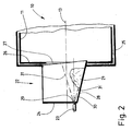
- Fig. 2 is an example schematically the arrangement of a sensor organ for Determining the presence of laundry items in an input hopper 22 shown.
- the sensor element is a Ultrasonic sensor 23.
- the ultrasonic sensor 23 is attached to the input hopper 22, and although on an end wall 24 thereof.
- the input hopper 22 is again firmly on a housing 25, the drum 11 at least in the initial area assigned.
- the drum 11 has at the end face 26 a circular opening 27.
- the opening 27 extends only over a central part of the end face 26 of the drum 11, but may be larger.
- the end wall 24 of the input hopper 22 extends in the illustrated embodiment at a distance parallel to the vertical end face 26 of the drum 11. It is also conceivable, the end wall 24 of the input hopper 22 obliquely and / or arcuately to Run end face 26. It is crucial that the end wall 24 of the Front side 26 of the drum 11 is spaced. In addition to the end wall 24 has the Input funnel 22 is still on a trough-shaped curved floor panel 28. The deepest Position of the floor panel lies on the vertical longitudinal center plane of the drum 11 and is directed obliquely into the opening 27 in the end face 26 of the drum 11, so that the items of laundry 21 are caused by gravity, preferably with the addition of water, pass through the opening 27 in the drum 11.
- the ultrasonic sensor 23 is at a small distance above the lowest point (apex line) of the bottom plate 28 on the end wall 24th attached to the input hopper 22. This attachment is made such that the ultrasonic sensor 23 is located outside the input hopper 22, so from the laundry items 21 is not affected.
- a small opening 29 in the end wall 24 of the Input hopper 22 the sound waves of the ultrasonic sensor 23 in the input hopper 22 arrive and reflected sound waves from the ultrasonic sensor 23 again be received.
- the ultrasonic sensor 23 in a with a threaded opening in the end wall 24 of the input hopper 22nd screwing in, preferably only so far as to send out and Receive reflected ultrasonic waves front side, namely measurement side of the Ultrasonic sensor 23 is approximately flush with the inner surface of the end wall 24.
- a measuring axis 30 of the ultrasonic sensor 23 with small distance above the lowest point of the bottom plate 28 on the opening 27 of the Drum 11 runs.
- a from the ultrasonic sensor 23 in the direction of the opening 27 of the Drum 11 emitted sound wave cone 31 is shown in dashed lines in Fig. 1, idealized.
- the sound wave cone 31 extends through the opening 27 in the interior of the drum 11, if there is no item of laundry 21 in the input hopper 22nd located.
- FIG. 3 shows an alternative arrangement of the ultrasonic sensor 23 on the end wall 24 of the input hopper 24.
- the input hopper 22, the drum 11 and also the housing 25 are formed as in the embodiment of FIG. 2, so that for same parts same reference numerals are used.
- the ultrasonic sensor 23 is slightly above the longitudinal central axis 13 of the drum 11th arranged, with a comparison with the embodiment of FIG. 2 larger Inclination.
- the measuring axis 30 extends through the opening 27 in the End face 26 of the drum 11 through to the inside of the drum 11.
- the Sound wave cone 31 extends with its lower portion through a lower Section of the opening 27 in the drum 11. This can also be reliably determined if still a laundry 21, even if it was just a single, flat lying Laundry item 21, located in the input hopper 22.
- the laundry is first washed in the washing zone 14, preferably in at least one in the direction of passage 17 of the laundry at the beginning of the drum 11 itself prewashed treatment chamber 18 and in subsequent treatment chambers 18 of the washing zone 14 washed clear. Following the washing zone 14 the laundry is brought to a lower temperature compared to the washing zone. This is followed by the last treatment chamber 18 of the washing zone 14 and indeed optionally the last treatment chamber 18, the final wash zone, the Treatment chambers 20. Due to the fact that the treatment chambers 20 longer than the remaining treatment chambers 18, 19 are formed, have these treatment chambers 20 over a larger chamber volume.
- Treatment chambers 20 This will change the filling ratio of Treatment chambers 20 increases by the laundry item with a specific Amount of laundry, which also passes through the other treatment chambers 18, 19, a larger chamber volume is provided.
- the result is that the laundry is in the cooling down treatment chambers 20 by a subcharge same loosely or relaxed. This can make the laundry more effective are cooled down and there is no appreciable creasing.
- the method according to the invention is particularly suitable for wet treatment, in particular washing, of so-called wrinkle-poor laundry of blended fabric.
- the increase of the filling ratio of the laundry in the treatment chambers 20 may be 10 to 50 percent, preferably 25 to 40 percent. Specifically, in the longer treatment chambers 20 underfill present by the treatment chambers 20 in relation to the chamber volume only 2/3 are filled with laundry. In this way, in the treatment chamber 20, the temperature of the laundry is about 3 to 6 ° C per minute, in particular about 4 ° C per minute, cooled down become.
- the ultrasonic sensor 23 is acoustic, by an acoustic distance measurement determines whether there is still a piece of laundry 21 in the hopper 21 or Not.
- the ultrasonic sensor 23 operates on the principle of a sonar.
- the ultrasonic sensor 23 measures a distance larger is as the distance of the provided with the ultrasonic sensor 23 end wall 24 to End face 26 of the drum 11.
- the sound wave cone 31 of the ultrasonic sensor 23 can then namely unhindered through the opening 27 in the end wall 26 in the Drum 11 extend.
- Is located in the input hopper 22 at least one garment 21, as shown in FIG. 2 and 3 is indicated, depending on the size of the laundry item 21 and the Wäsche Publishedhaufens the whole sound wave cone 31 or only a part of it on the Input hopper 22 located laundry 21.
- the ultrasonic sensor 23 measures only the distance from the end wall 24 to the laundry 21 or Wäsche Publishedhaufen. This distance is significantly shorter than the distance of the end wall 24 of the Input hopper 22 to the end face 26 of the drum 11. Such a shorter distance is detected by the ultrasonic sensor 23 even if only a part of the sound wave cone 31 on the laundry 21 and the laundry pile meets (Fig. 2).
- the ultrasonic sensor 23 so on the end wall 24 of the input hopper 22 is attached, that the sound wave cone 31 at least with a lower portion the lowest point so the vertex of the trough-like hollow plate 28 of the Input hopper 22 covers, can also lying flat, individual items of laundry 21 after the distance measuring method described above non-contact, namely acoustically, be detected.
- the measuring signals of the ultrasonic sensor 23 are used to the washing of the Continuous washing machine 10 to start only when all laundry items 21 on the Input hopper 22 have passed into the drum 11, so the input hopper 22 is empty. As long as this is not the case, prevents the ultrasonic sensor 23 and a so contiguous control of the continuous washing machine 10 the beginning of Washing process. Only when the input hopper 22 is completely empty, the Start washing process. The washing process is then either by the ultrasonic sensor 23 initiated by this starts the wash program when the input funnel 22 completely empty. Alternatively, it is possible for the ultrasonic sensor 23 to be in the control the continuous washing machine 10 involve that the wash program only started can be when the ultrasonic sensor 23 detects that the input hopper 22nd completely empty.
Landscapes
- Engineering & Computer Science (AREA)
- Textile Engineering (AREA)
- Accessory Of Washing/Drying Machine, Commercial Washing/Drying Machine, Other Washing/Drying Machine (AREA)
- Treatment Of Fiber Materials (AREA)
- Control Of Washing Machine And Dryer (AREA)
Abstract
Description
- Fig. 1
- eine schematische Seitenansicht einer Vorrichtung, nämlich einer Durchlaufwaschmaschine, die auch zur Durchführung des erfindungsgemäßen Verfahrens geeignet ist,
- Fig. 2
- eine schematische Darstellung eines vorderen Bereichs der Durchlaufwaschmaschine mit einem Einlauftrichter, und
- Fig. 3
- ein alternatives Ausführungsbeispiel der Erfindung in einer Ansicht analog zur Fig. 2.
- 10
- Durchlaufwaschmaschine
- 11
- Trommel
- 12
- Trommelmantel
- 13
- Längsmittelachse
- 14
- Waschzone
- 15
- Kühlzone
- 16
- Spülzone
- 17
- Durchlaufrichtung
- 18
- Behandlungskammer
- 19
- Behandlungskammer
- 20
- Behandlungskammer
- 21
- Wäschestück
- 22
- Eingabetrichter
- 23
- Ultraschallsensor
- 24
- Stirnwandung
- 25
- Gehäuse
- 26
- Stirnseite
- 27
- Öffnung
- 28
- Bodenblech
- 29
- Öffnung
- 30
- Messachse
- 31
- Schallwellenkegel
Claims (10)
- Verfahren zur Nassbehandlung von insbesondere Wäsche, wobei die Wäsche in einer drehend antreibbaren Trommel (11) zumindest gewaschen wird, die Trommel (11) aufeinander folgende Behandlungskammern (18, 19, 20, 21) aufweist, durch die die Wäsche während der Nassbehandlung hindurchgeleitet wird, und in mindestens einer Behandlungskammer (20) die Temperatur der Wäsche verringert wird, dadurch gekennzeichnet, dass in mindestens derjenigen Behandlungskammer (20), in der die Temperatur der Wäsche verringert wird, das Kammervolumen gegenüber der Menge der Wäsche (Füllverhältnis) erhöht wird.
- Verfahren nach Anspruch 1, dadurch gekennzeichnet, dass das Füllverhältnis derart vergrößert wird, dass in der Taktzeit der Behandlung der Wäsche in den übrigen Behandlungskammern (18, 19) die Wäsche auf die vorgesehene Temperatur herunter gekühlt wird.
- Verfahren nach einem der vorhergehenden Ansprüche, dadurch gekennzeichnet, dass das Füllverhältnis dadurch vergrößert wird, dass mindestens diejenige Behandlungskammer (20), in der die Temperatur der Wäsche reduziert wird, ein größeres Kammervolumen gegenüber mindestens einem Großteil der übrigen Behandlungskammern (18, 19) aufweist, insbesondere das Volumen der oder jeder Behandlungskammer (20) vergrößert wird, indem die oder jede betreffende Behandlungskammer (20) verlängert wird, vorzugsweise in Richtung der Hindurchleitung der Wäsche durch die Trommel (11) bzw. die Behandlungskammern (18, 19, 20).
- Verfahren zur insbesondere Nassbehandlung von vorzugsweise Wäsche, wobei die Wäsche über einen Eingabetrichter (22) durch eine Stirnseite (26) einer drehend antreibbaren Trommel (11) in die Trommel (11) eingegeben wird und die Wäsche anschließend in der drehend angetriebenen Trommel (11) gewaschen wird, vorzugsweise nach einem der vorhergehenden Ansprüche, dadurch gekennzeichnet ,dass durch mindestens ein nach Art eines Entfernungsmessers arbeitendes Sensororgan festgestellt wird, ob Wäsche im Eingabetrichter (22) vorhanden ist oder nicht.
- Verfahren nach Anspruch 4, dadurch gekennzeichnet, dass vom Sensororgan festgestellt wird, ob der Vorgang des Beladens der Trommel (11) mit Wäsche abgeschlossen ist, vorzugsweise das Sensororgan die Beendigung des Beladens feststellt, wenn sich kein Wäschestück (21) im Eingabetrichter (22) mehr befindet, und danach der Waschvorgang vom Sensororgan gestartet wird oder das Sensororgan einen Start des Waschprogramms zulässt.
- Vorrichtung zur Nassbehandlung von insbesondere Wäsche mit einer umlaufend antreibbaren Trommel (11) die in einer Durchlaufrichtung (17) der Wäsche aufeinander folgende Behandlungskammern (18, 19, 20, 21) aufweist, dadurch gekennzeichnet, dass mindestens eine Behandlungskammer (20) in der eine Verringerung der Temperatur der Wäsche erfolgt ein größeres Volumen (Kammervolumen) aufweist als alle oder mindestens die meisten übrigen Behandlungskammern (18, 19).
- Vorrichtung nach Anspruch 6, dadurch gekennzeichnet, dass mindestens eine Behandlungskammer (20) in der eine Verringerung der Temperatur der Wäsche erfolgt in Längsrichtung der Trommel (11) eine größere Abmessung, insbesondere eine größere Länge, aufweist, wobei vorzugsweise der Durchmesser der oder jeder Behandlungskammer (20) zur Verringerung der Temperatur der Wäsche etwa gleich dem Durchmesser der übrigen Behandlungskammern (18, 19) ist, insbesondere alle Behandlungskammern (18, 19, 20) einen etwa gleichen Durchmesser aufweisen und in der gemeinsamen Trommel (11) untergebracht sind.
- Vorrichtung zur insbesondere Nassbehandlung von vorzugsweise Wäsche, mit einer umlaufend antreibbaren Trommel (11), und einem einer mindestens teilweise offenen Stirnseite (26) der Trommel (11) zugeordneten Eingabetrichter (22), vorzugsweise nach einem der vorhergehenden Ansprüche, dadurch gekennzeichnet, dass dem Eingabetrichter (22) mindestens ein ein Abstandssignal lieferndes Sensororgan zugeordnet ist.
- Vorrichtung nach Anspruch 8, dadurch gekennzeichnet, dass das Sensororgan überwiegend in einem unteren Bodenbereich des Eingabetrichters (22) misst, wozu das Sensororgan vorzugsweise einer Stirnwandung (24) des Eingabetrichters (22) zugeordnet ist, insbesondere einer Öffnung (27) in der Stirnwandung (24) des Eingabetrichters (22).
- Vorrichtung nach Anspruch 8, dadurch gekennzeichnet, dass das Sensororgan zur dem Eingabetrichter (22) zugeordneten Stirnseite (26) der Trommel (11) gerichtet ist, vorzugsweise in eine Öffnung (27) in der genannten Stirnseite (26) der Trommel (11), wobei insbesondere das Sensororgan mindestens den Abstand desselben zur Stirnseite (26) der Trommel (11) misst, vorzugsweise akustisch, indem das Sensororgan beispielsweise als ein Ultraschallsensor (23) ausgebildet ist.
Applications Claiming Priority (4)
| Application Number | Priority Date | Filing Date | Title |
|---|---|---|---|
| DE10205161 | 2002-02-07 | ||
| DE10205161 | 2002-02-07 | ||
| DE10238358A DE10238358A1 (de) | 2002-02-07 | 2002-08-16 | Verfahren und Vorrichtung zur Nassbehandlung von insbesondere Wäsche |
| DE10238358 | 2002-08-16 |
Publications (3)
| Publication Number | Publication Date |
|---|---|
| EP1335058A2 true EP1335058A2 (de) | 2003-08-13 |
| EP1335058A3 EP1335058A3 (de) | 2007-06-27 |
| EP1335058B1 EP1335058B1 (de) | 2016-10-26 |
Family
ID=27614270
Family Applications (1)
| Application Number | Title | Priority Date | Filing Date |
|---|---|---|---|
| EP03001919.4A Expired - Lifetime EP1335058B1 (de) | 2002-02-07 | 2003-01-30 | Vorrichtung zur nassbehandlung von insbesondere wäsche |
Country Status (1)
| Country | Link |
|---|---|
| EP (1) | EP1335058B1 (de) |
Family Cites Families (7)
| Publication number | Priority date | Publication date | Assignee | Title |
|---|---|---|---|---|
| GB1334300A (en) * | 1970-07-16 | 1973-10-17 | Ato Inc | Laundry apparatus |
| AT317822B (de) * | 1972-05-19 | 1974-09-10 | Meyer Arnfried | Durchlauftrommelmaschine, insbesondere zum Trocknen von Wäsche |
| AT346271B (de) * | 1977-02-25 | 1978-11-10 | Poensgen & Sulzmann Gmbh Geb | Durchlauftrommelmaschine zum behandeln von textilgutposten |
| CH665231A5 (de) * | 1982-03-01 | 1988-04-29 | Schulthess & Co Ag Maschf | Verfahren zum waschen von waesche und durchlaufwaschmaschine zur ausfuehrung des verfahrens. |
| CH660046A5 (en) * | 1983-06-29 | 1987-03-13 | Schulthess & Co Ag Maschf | Continuous-flow washing machine with an arrangement for feeding media into at least one chamber of a washing drum |
| DE3631867C2 (de) * | 1986-09-19 | 1996-02-08 | Transferon Waeschereimasch | Postendurchlaufwaschmaschine |
| DE10031040B4 (de) * | 1999-08-11 | 2006-01-26 | Pharmagg Systemtechnik Gmbh | Verfahren und Vorrichtung zur Naßbehandlung von Wäschestücken |
-
2003
- 2003-01-30 EP EP03001919.4A patent/EP1335058B1/de not_active Expired - Lifetime
Also Published As
| Publication number | Publication date |
|---|---|
| EP1335058B1 (de) | 2016-10-26 |
| EP1335058A3 (de) | 2007-06-27 |
Similar Documents
| Publication | Publication Date | Title |
|---|---|---|
| DE602004004558T2 (de) | Flottenumwälzende Haushaltswasmaschine mit automatischer Bestimmung des Wäschegewichts, sowie zugehöriges Betriebsverfahren. | |
| DE68928640T2 (de) | Trommelwaschmaschine | |
| DE102008058267B4 (de) | Waschmaschine | |
| DE69923830T2 (de) | Kombinierte Waschmaschine | |
| DE4203416C2 (de) | Verfahren zur Reinigung des Trocknungskondensators in einem Wäschetrockner | |
| DE602005004901T2 (de) | Wasserumwälzende Haushaltwaschmaschine mit automatischer Wäscharterfassung und dazugehörigem Verfahren | |
| DE102008058268B4 (de) | Waschmaschine | |
| EP1932960A2 (de) | Verfahren zur Steuerung einer Waschmaschine | |
| EP2133455A1 (de) | Verfahren und Einrichtung zum Bestimmen von Schaum in einer Waschmaschine | |
| DE112006000088T5 (de) | Dampfgenerator und Wäschemaschine mit einem solchen | |
| DE69519281T2 (de) | Spülverfahren für Waschmaschine | |
| WO2011054761A1 (de) | Verfahren zum reinigen eines waschtrockners und hierfür geeigneter waschtrockner | |
| DE102012223433A1 (de) | Wäschebehandlungsgerät mit entnehmbarem Flüssigkeitsbehälter | |
| DE102007033493A1 (de) | Verfahren zur Behandlung von Wäsche sowie hierzu geeignete programmgesteuerte Waschmaschine | |
| DE10035904A1 (de) | Vorrichtung zur Nassbehandlung von Wäsche | |
| DE60010201T2 (de) | Dampfkondensationskammer für eine Geschirrspülmaschine | |
| DE112017000598T5 (de) | Trommelwaschmaschine und verfahren zum reinigen einer wanne derselben | |
| DE102009046546A1 (de) | Wasserführendes Hausgerät mit einer Dosiereinrichtung und einer Steuerung | |
| DE102007036800A1 (de) | Verfahren zur Nassbehandlung von Wäschestücken | |
| DE102005003694A1 (de) | Verfahren zum Reinigen und Imprägnieren von Textilien | |
| EP1995364B1 (de) | Verfahren zur Nassbehandlung von Wäschestücken | |
| DE10238358A1 (de) | Verfahren und Vorrichtung zur Nassbehandlung von insbesondere Wäsche | |
| DE102008054392A1 (de) | Mitnehmer, Wäschetrommel und Waschmaschine | |
| DE102011004949A1 (de) | Geschirrspülmaschine und Verfahren zum Betrieb derselben | |
| EP3219842B1 (de) | Verfahren zur nassbehandlung von wäsche |
Legal Events
| Date | Code | Title | Description |
|---|---|---|---|
| PUAI | Public reference made under article 153(3) epc to a published international application that has entered the european phase |
Free format text: ORIGINAL CODE: 0009012 |
|
| AK | Designated contracting states |
Designated state(s): AT BE BG CH CY CZ DE DK EE ES FI FR GB GR HU IE IT LI LU MC NL PT SE SI SK TR |
|
| AX | Request for extension of the european patent |
Extension state: AL LT LV MK RO SI |
|
| 17P | Request for examination filed |
Effective date: 20060823 |
|
| PUAL | Search report despatched |
Free format text: ORIGINAL CODE: 0009013 |
|
| AK | Designated contracting states |
Kind code of ref document: A3 Designated state(s): AT BE BG CH CY CZ DE DK EE ES FI FR GB GR HU IE IT LI LU MC NL PT SE SI SK TR |
|
| AX | Request for extension of the european patent |
Extension state: AL LT LV MK RO |
|
| AKX | Designation fees paid |
Designated state(s): AT BE BG CH CY CZ DE DK EE ES FI FR GB GR HU IE IT LI LU MC NL PT SE SI SK TR |
|
| 17Q | First examination report despatched |
Effective date: 20081105 |
|
| GRAP | Despatch of communication of intention to grant a patent |
Free format text: ORIGINAL CODE: EPIDOSNIGR1 |
|
| INTG | Intention to grant announced |
Effective date: 20160509 |
|
| GRAS | Grant fee paid |
Free format text: ORIGINAL CODE: EPIDOSNIGR3 |
|
| GRAA | (expected) grant |
Free format text: ORIGINAL CODE: 0009210 |
|
| AK | Designated contracting states |
Kind code of ref document: B1 Designated state(s): AT BE BG CH CY CZ DE DK EE ES FI FR GB GR HU IE IT LI LU MC NL PT SE SI SK TR |
|
| REG | Reference to a national code |
Ref country code: GB Ref legal event code: FG4D Free format text: NOT ENGLISH |
|
| REG | Reference to a national code |
Ref country code: CH Ref legal event code: EP |
|
| REG | Reference to a national code |
Ref country code: AT Ref legal event code: REF Ref document number: 840117 Country of ref document: AT Kind code of ref document: T Effective date: 20161115 |
|
| REG | Reference to a national code |
Ref country code: IE Ref legal event code: FG4D Free format text: LANGUAGE OF EP DOCUMENT: GERMAN |
|
| REG | Reference to a national code |
Ref country code: DE Ref legal event code: R096 Ref document number: 50315566 Country of ref document: DE |
|
| REG | Reference to a national code |
Ref country code: FR Ref legal event code: PLFP Year of fee payment: 15 |
|
| REG | Reference to a national code |
Ref country code: NL Ref legal event code: MP Effective date: 20161026 |
|
| PG25 | Lapsed in a contracting state [announced via postgrant information from national office to epo] |
Ref country code: SE Free format text: LAPSE BECAUSE OF FAILURE TO SUBMIT A TRANSLATION OF THE DESCRIPTION OR TO PAY THE FEE WITHIN THE PRESCRIBED TIME-LIMIT Effective date: 20161026 Ref country code: GR Free format text: LAPSE BECAUSE OF FAILURE TO SUBMIT A TRANSLATION OF THE DESCRIPTION OR TO PAY THE FEE WITHIN THE PRESCRIBED TIME-LIMIT Effective date: 20170127 |
|
| PG25 | Lapsed in a contracting state [announced via postgrant information from national office to epo] |
Ref country code: FI Free format text: LAPSE BECAUSE OF FAILURE TO SUBMIT A TRANSLATION OF THE DESCRIPTION OR TO PAY THE FEE WITHIN THE PRESCRIBED TIME-LIMIT Effective date: 20161026 Ref country code: NL Free format text: LAPSE BECAUSE OF FAILURE TO SUBMIT A TRANSLATION OF THE DESCRIPTION OR TO PAY THE FEE WITHIN THE PRESCRIBED TIME-LIMIT Effective date: 20161026 Ref country code: BE Free format text: LAPSE BECAUSE OF NON-PAYMENT OF DUE FEES Effective date: 20170131 Ref country code: ES Free format text: LAPSE BECAUSE OF FAILURE TO SUBMIT A TRANSLATION OF THE DESCRIPTION OR TO PAY THE FEE WITHIN THE PRESCRIBED TIME-LIMIT Effective date: 20161026 Ref country code: PT Free format text: LAPSE BECAUSE OF FAILURE TO SUBMIT A TRANSLATION OF THE DESCRIPTION OR TO PAY THE FEE WITHIN THE PRESCRIBED TIME-LIMIT Effective date: 20170227 |
|
| REG | Reference to a national code |
Ref country code: DE Ref legal event code: R097 Ref document number: 50315566 Country of ref document: DE |
|
| PG25 | Lapsed in a contracting state [announced via postgrant information from national office to epo] |
Ref country code: SK Free format text: LAPSE BECAUSE OF FAILURE TO SUBMIT A TRANSLATION OF THE DESCRIPTION OR TO PAY THE FEE WITHIN THE PRESCRIBED TIME-LIMIT Effective date: 20161026 Ref country code: DK Free format text: LAPSE BECAUSE OF FAILURE TO SUBMIT A TRANSLATION OF THE DESCRIPTION OR TO PAY THE FEE WITHIN THE PRESCRIBED TIME-LIMIT Effective date: 20161026 Ref country code: EE Free format text: LAPSE BECAUSE OF FAILURE TO SUBMIT A TRANSLATION OF THE DESCRIPTION OR TO PAY THE FEE WITHIN THE PRESCRIBED TIME-LIMIT Effective date: 20161026 Ref country code: CZ Free format text: LAPSE BECAUSE OF FAILURE TO SUBMIT A TRANSLATION OF THE DESCRIPTION OR TO PAY THE FEE WITHIN THE PRESCRIBED TIME-LIMIT Effective date: 20161026 |
|
| PG25 | Lapsed in a contracting state [announced via postgrant information from national office to epo] |
Ref country code: BG Free format text: LAPSE BECAUSE OF FAILURE TO SUBMIT A TRANSLATION OF THE DESCRIPTION OR TO PAY THE FEE WITHIN THE PRESCRIBED TIME-LIMIT Effective date: 20170126 Ref country code: IT Free format text: LAPSE BECAUSE OF FAILURE TO SUBMIT A TRANSLATION OF THE DESCRIPTION OR TO PAY THE FEE WITHIN THE PRESCRIBED TIME-LIMIT Effective date: 20161026 |
|
| PLBE | No opposition filed within time limit |
Free format text: ORIGINAL CODE: 0009261 |
|
| STAA | Information on the status of an ep patent application or granted ep patent |
Free format text: STATUS: NO OPPOSITION FILED WITHIN TIME LIMIT |
|
| PG25 | Lapsed in a contracting state [announced via postgrant information from national office to epo] |
Ref country code: MC Free format text: LAPSE BECAUSE OF FAILURE TO SUBMIT A TRANSLATION OF THE DESCRIPTION OR TO PAY THE FEE WITHIN THE PRESCRIBED TIME-LIMIT Effective date: 20161026 |
|
| 26N | No opposition filed |
Effective date: 20170727 |
|
| REG | Reference to a national code |
Ref country code: IE Ref legal event code: MM4A |
|
| PG25 | Lapsed in a contracting state [announced via postgrant information from national office to epo] |
Ref country code: SI Free format text: LAPSE BECAUSE OF FAILURE TO SUBMIT A TRANSLATION OF THE DESCRIPTION OR TO PAY THE FEE WITHIN THE PRESCRIBED TIME-LIMIT Effective date: 20161026 Ref country code: LU Free format text: LAPSE BECAUSE OF NON-PAYMENT OF DUE FEES Effective date: 20170130 |
|
| REG | Reference to a national code |
Ref country code: FR Ref legal event code: PLFP Year of fee payment: 16 |
|
| PGFP | Annual fee paid to national office [announced via postgrant information from national office to epo] |
Ref country code: FR Payment date: 20171221 Year of fee payment: 16 |
|
| REG | Reference to a national code |
Ref country code: BE Ref legal event code: MM Effective date: 20170131 |
|
| PG25 | Lapsed in a contracting state [announced via postgrant information from national office to epo] |
Ref country code: IE Free format text: LAPSE BECAUSE OF NON-PAYMENT OF DUE FEES Effective date: 20170130 |
|
| PGFP | Annual fee paid to national office [announced via postgrant information from national office to epo] |
Ref country code: GB Payment date: 20180124 Year of fee payment: 16 Ref country code: CH Payment date: 20180115 Year of fee payment: 16 |
|
| PGFP | Annual fee paid to national office [announced via postgrant information from national office to epo] |
Ref country code: AT Payment date: 20171228 Year of fee payment: 16 |
|
| PG25 | Lapsed in a contracting state [announced via postgrant information from national office to epo] |
Ref country code: HU Free format text: LAPSE BECAUSE OF FAILURE TO SUBMIT A TRANSLATION OF THE DESCRIPTION OR TO PAY THE FEE WITHIN THE PRESCRIBED TIME-LIMIT; INVALID AB INITIO Effective date: 20030130 |
|
| REG | Reference to a national code |
Ref country code: CH Ref legal event code: PL |
|
| REG | Reference to a national code |
Ref country code: AT Ref legal event code: MM01 Ref document number: 840117 Country of ref document: AT Kind code of ref document: T Effective date: 20190130 |
|
| GBPC | Gb: european patent ceased through non-payment of renewal fee |
Effective date: 20190130 |
|
| PG25 | Lapsed in a contracting state [announced via postgrant information from national office to epo] |
Ref country code: FR Free format text: LAPSE BECAUSE OF NON-PAYMENT OF DUE FEES Effective date: 20190131 Ref country code: CY Free format text: LAPSE BECAUSE OF NON-PAYMENT OF DUE FEES Effective date: 20161026 |
|
| PG25 | Lapsed in a contracting state [announced via postgrant information from national office to epo] |
Ref country code: AT Free format text: LAPSE BECAUSE OF NON-PAYMENT OF DUE FEES Effective date: 20190130 Ref country code: CH Free format text: LAPSE BECAUSE OF NON-PAYMENT OF DUE FEES Effective date: 20190131 Ref country code: LI Free format text: LAPSE BECAUSE OF NON-PAYMENT OF DUE FEES Effective date: 20190131 Ref country code: GB Free format text: LAPSE BECAUSE OF NON-PAYMENT OF DUE FEES Effective date: 20190130 |
|
| PG25 | Lapsed in a contracting state [announced via postgrant information from national office to epo] |
Ref country code: TR Free format text: LAPSE BECAUSE OF FAILURE TO SUBMIT A TRANSLATION OF THE DESCRIPTION OR TO PAY THE FEE WITHIN THE PRESCRIBED TIME-LIMIT Effective date: 20161026 |
|
| PGFP | Annual fee paid to national office [announced via postgrant information from national office to epo] |
Ref country code: DE Payment date: 20200130 Year of fee payment: 18 |
|
| REG | Reference to a national code |
Ref country code: DE Ref legal event code: R119 Ref document number: 50315566 Country of ref document: DE |
|
| PG25 | Lapsed in a contracting state [announced via postgrant information from national office to epo] |
Ref country code: DE Free format text: LAPSE BECAUSE OF NON-PAYMENT OF DUE FEES Effective date: 20210803 |