EP1334228B1 - Bullaugentür für eine von vorn beschickbare trommelwaschmaschine - Google Patents
Bullaugentür für eine von vorn beschickbare trommelwaschmaschine Download PDFInfo
- Publication number
- EP1334228B1 EP1334228B1 EP01988798A EP01988798A EP1334228B1 EP 1334228 B1 EP1334228 B1 EP 1334228B1 EP 01988798 A EP01988798 A EP 01988798A EP 01988798 A EP01988798 A EP 01988798A EP 1334228 B1 EP1334228 B1 EP 1334228B1
- Authority
- EP
- European Patent Office
- Prior art keywords
- cover
- retaining ring
- bullseye
- ring
- door according
- Prior art date
- Legal status (The legal status is an assumption and is not a legal conclusion. Google has not performed a legal analysis and makes no representation as to the accuracy of the status listed.)
- Expired - Lifetime
Links
- 238000005406 washing Methods 0.000 title claims abstract description 10
- 239000011521 glass Substances 0.000 claims abstract description 20
- 239000005357 flat glass Substances 0.000 claims abstract description 5
- 238000010276 construction Methods 0.000 claims 1
- 238000007689 inspection Methods 0.000 abstract 2
- 238000005538 encapsulation Methods 0.000 description 3
- 238000004026 adhesive bonding Methods 0.000 description 2
- 238000000034 method Methods 0.000 description 2
- 239000000203 mixture Substances 0.000 description 2
- 230000001154 acute effect Effects 0.000 description 1
- 238000001816 cooling Methods 0.000 description 1
- 238000005520 cutting process Methods 0.000 description 1
- 238000002347 injection Methods 0.000 description 1
- 239000007924 injection Substances 0.000 description 1
- 238000009434 installation Methods 0.000 description 1
- 230000001788 irregular Effects 0.000 description 1
- 238000004519 manufacturing process Methods 0.000 description 1
- 238000007493 shaping process Methods 0.000 description 1
- 125000006850 spacer group Chemical group 0.000 description 1
- 239000012815 thermoplastic material Substances 0.000 description 1
Images

Classifications
-
- D—TEXTILES; PAPER
- D06—TREATMENT OF TEXTILES OR THE LIKE; LAUNDERING; FLEXIBLE MATERIALS NOT OTHERWISE PROVIDED FOR
- D06F—LAUNDERING, DRYING, IRONING, PRESSING OR FOLDING TEXTILE ARTICLES
- D06F37/00—Details specific to washing machines covered by groups D06F21/00 - D06F25/00
- D06F37/02—Rotary receptacles, e.g. drums
- D06F37/04—Rotary receptacles, e.g. drums adapted for rotation or oscillation about a horizontal or inclined axis
- D06F37/10—Doors; Securing means therefor
-
- D—TEXTILES; PAPER
- D06—TREATMENT OF TEXTILES OR THE LIKE; LAUNDERING; FLEXIBLE MATERIALS NOT OTHERWISE PROVIDED FOR
- D06F—LAUNDERING, DRYING, IRONING, PRESSING OR FOLDING TEXTILE ARTICLES
- D06F37/00—Details specific to washing machines covered by groups D06F21/00 - D06F25/00
- D06F37/26—Casings; Tubs
- D06F37/261—Tubs made by a specially selected manufacturing process or characterised by their assembly from elements
- D06F37/262—Tubs made by a specially selected manufacturing process or characterised by their assembly from elements made of plastic material, e.g. by injection moulding
-
- D—TEXTILES; PAPER
- D06—TREATMENT OF TEXTILES OR THE LIKE; LAUNDERING; FLEXIBLE MATERIALS NOT OTHERWISE PROVIDED FOR
- D06F—LAUNDERING, DRYING, IRONING, PRESSING OR FOLDING TEXTILE ARTICLES
- D06F37/00—Details specific to washing machines covered by groups D06F21/00 - D06F25/00
- D06F37/26—Casings; Tubs
- D06F37/28—Doors; Security means therefor
-
- D—TEXTILES; PAPER
- D06—TREATMENT OF TEXTILES OR THE LIKE; LAUNDERING; FLEXIBLE MATERIALS NOT OTHERWISE PROVIDED FOR
- D06F—LAUNDERING, DRYING, IRONING, PRESSING OR FOLDING TEXTILE ARTICLES
- D06F39/00—Details of washing machines not specific to a single type of machines covered by groups D06F9/00 - D06F27/00
- D06F39/12—Casings; Tubs
- D06F39/14—Doors or covers; Securing means therefor
Definitions
- the invention relates to a porthole door for a front-loading drum washing machine with a frame hinged to the washing machine housing from a support ring and a retaining ring and with a towards the drum interior cup-shaped sighted sight glass, approximately in the plane of the outer retaining ring of the frame with a cover against Access is protected, with the edge of the cover is attached to the frame,
- Such a porthole door is known from DE 195 15 040 C2.
- a slightly curved glass is used as the cover, the edge of which is stepped, so that on its outer side an annular space is formed, in which the flange of a blend ring finds enough space, that the outer surfaces of the blend ring and the glass of the cover are approximately flush.
- the invention has the object of providing a porthole door of the type mentioned in such a way that less complicated frame parts can be used, that the fits between the parts of a porthole door can be narrower and that the appearance of the porthole door meets modern aesthetic expectations.
- this object is achieved in a porthole door described above in that the cover consists of a cooled over a model mold flat glass.
- a flat glass can be pulled so homogeneously that irregular refractions are largely ruled out.
- Cool freshly drawn flat glasses on desired model forms, z. B. dome shapes so they follow the surface shape and yet do not lose their homogeneous structure.
- covers of the type according to the invention can satisfy aesthetic demands in a porthole door. They are also manufactured with significantly lower tolerances, because their outer shape and dimensions only after cooling by using cutting techniques be determined for hard glasses and can therefore be held by considerably filigree parts on the frame of the porthole door.
- the cover is included on its narrow shell side of the retaining ring.
- the retaining ring can therefore be designed on the periphery of the cover so filigree and flush with no gap between them and the cover that can be met with such a cover held the claim of novel aesthetic shaping of Bullaugene.
- this claim can be supported by the fact that the retaining ring has a flat portion, which rests from the inside at the edge of the cover. As a result, at the same time the parts for the attachment of the cover can be reduced, so that overall a cost advantage for the production of the portholes door is achieved.
- the retaining ring is formed in two parts according to a further advantageous embodiment of the invention and consists of a flat part containing part and a pressure ring with an outer diameter equal to the inner diameter of the flat portion and if also the pressure ring between the inside of the cover on the one hand and the outside of a flange of the sight glass
- the cover can be connected to the flat part containing part and the pressure ring, for example, by gluing technique during installation of the Bullaugene first, without having to pay attention to several loose parts and their correct fit during assembly , This allows a more accurate connection between the frame parts and the cover.
- the porthole door has an advantageous appearance in that the part of the retaining ring containing the flat part has a narrow edge, which engages over the edge of the cover in a width smaller than the thickness of the cover towards the front.
- the aesthetic appearance of the porthole door is particularly supported by the fact that the cover is glued to the retaining ring. This eliminates optically disturbing fastening devices.
- the retaining ring may be glued according to a particular development of the invention with the front end face of the sight glass. As a result, a step-by-step approach is possible during assembly of the porthole door, in which the parts can be paid attention to each other without problems on full-surface and centered seat.
- the cover is encapsulated with the edge part of the retaining ring made of thermoplastic material.
- the cover may have a slightly conically shaped edge, the oblique surface is filled by the edge portion of the thermoplastic-shaped retaining ring and thus can be already held on the retaining ring.
- the washing machine 1 shown in Figure 1 includes a porthole door 2 for closing the feed opening 3.
- the porthole door is laterally hinged to the feed opening 3 and includes a frame 4 with mounted, topffömig pressed sight glass 5, which fills the depth of the feed opening 3 so far that the circular inner surface of the sight glass 5 is approximately flush with the opening of a washing drum, not shown, rotating within the washing machine.
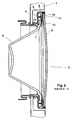
- the porthole door 2 shown cut in Figure 2 includes a three-part frame 4, the support ring 6 has a substantially angular cross section and on the one hand serves to hold the front flange 7 of the sight glass 5, and on the other hand as a plant and enclosure for the retaining ring 8, the for fastening the cover 9 at its approximately cylindrical edge is used.
- the retaining ring consists of a inside lying on the edge 10 of the cover 9 flat part 11 containing part and a pressure ring 12 whose outer diameter is equal to the inner diameter of the pressure ring 12.
- the pressure ring 12 has a V-shaped cross section with a very acute opening angle, so that the legs of the V can be easily pressed together elastically.
- the narrow outer surface of the cover 9 can be bevelled at the edge 10 so that the circular outer surface of the cover has a smaller diameter than the inner surface.
- the flat part 11 containing part of the retaining ring 8 may be formed as encapsulation of the edge portion 10 of the cover 9, whereby a flush arrangement of the narrow annular outer surface of the injection with the outer surface of the cover 9 can be achieved.
- the cylindrical part of the support ring 6 can then also be arranged flush with the outside of the encapsulation, or the cylindrical part of the support ring 6 can ever end on the inner surface of the retaining ring 8 and be there possibly glued. Then, such narrow annular surfaces of the encapsulation of the part with the flat part 11 around the cover 9 around, that thereby an aesthetically pleasing porthole can be achieved in a particularly simple manner.
Landscapes
- Engineering & Computer Science (AREA)
- Textile Engineering (AREA)
- Main Body Construction Of Washing Machines And Laundry Dryers (AREA)
- Component Parts Of Construction Machinery (AREA)
- Window Of Vehicle (AREA)
- Power-Operated Mechanisms For Wings (AREA)
Description
- Die Erfindung betrifft eine Bullaugentür für eine von vorn beschickbare Trommelwaschmaschine mit einem am Waschmaschinengehäuse scharnierten Rahmen aus einem Tragring und einem Haltering und mit einem in Richtung auf den Trommelinnenraum hin topfförmig eingezogenen Schauglas, das etwa in der Ebene des äußeren Halteringes des Rahmens mit einer Abdeckung gegen Zugriff geschützt ist, wobei der Rand der Abdeckung am Rahmen befestigt ist,
- Eine derartige Bullaugentür ist durch DE 195 15 040 C2 bekannt. Darin wird als Abdeckung ein leicht gewölbtes Glas verwendet, dessen Rand stufenförmig abgesetzt ist, damit an seiner Außenseite ein Ringraum entsteht, in den der Flansch eines Blendringes so Platz findet, dass die Außenflächen des Blendringes und des Glases der Abdeckung ungefähr flächenbündig sind.
- Das Glas für eine solche Abdeckung muss in einer Form gepresst werden, was ringförmige Rillen im Glas zurück lassen kann, so dass die an den Rillen erzeugten Strahlenbrechungen ein unästhetisches Bild ergeben. Außerdem sind Pressgläser extrem ungenau in ihren Abmessungen, so dass Montageteile immer einen verhältnismäßig großen Spielraum zum Glaskörper haben müssen. Dadurch sind große Spalte zwischen den Einzelteilen einer Bullaugentür gemäß Stand der Technik hinzunehmen.
- Der Erfindung liegt die Aufgabe zugrunde, eine Bullaugentür der eingangs genannten Art so auszubilden, dass weniger komplizierte Rahmenteile verwendet werden können, dass die Passungen zwischen den Einzelteilen einer Bullaugentür enger sein können und dass das äußere Erscheinungsbild der Bullaugentür den modernen ästhetischen Vorstellungen entspricht.
- Erfindungsgemäß wird diese Aufgabe bei einer eingangs beschriebenen Bullaugentür dadurch gelöst, dass die Abdeckung aus einem über einer Modellform abgekühlten Flachglas besteht. Ein solches Flachglas kann so homogen gezogen werden, dass unregelmäßige Strahlenbrechungen weitgehend auszuschließen sind. Kühlen frisch gezogene Flachgläser auf gewünschten Modellformen, z. B. Kalottenformen, ab, so folgen sie der Oberflächenform und verlieren dennoch nicht ihre homogene Struktur. Dadurch können Abdeckungen der erfindungsgemäßen Art ästhetische Ansprüche bei einer Bullaugentür befriedigen. Sie sind außerdem mit erheblich geringeren Toleranzen herstellbar, weil ihre äußere Form und ihre Abmessungen erst nach Abkühlen durch Einsatz von Schneidtechniken für harte Gläser bestimmt werden und können daher durch erheblich filigranere Teile am Rahmen der Bullaugentür gehalten werden.
- Eine vorteilhafte Weiterbildung der Erfindung ist daher dadurch gekennzeichnet, dass die Abdeckung an ihrer schmalen Mantelseite vom Haltering umfasst ist. Der Haltering kann an der Peripherie der Abdeckung daher derartig filigran und flächenbündig ohne Spalte zwischen sich und der Abdeckung gestaltet sein, dass mit einer derartig gehaltenen Abdeckung dem Anspruch an neuartig ästhetische Formung der Bullaugentür entsprochen werden kann.
- In besonders vorteilhafter Weise kann dieser Anspruch dadurch unterstützt werden, dass der Haltering eine Flachpartie hat, die von innen am Rand der Abdeckung anliegt. Dadurch können zugleich die Teile für die Befestigung der Abdeckung vermindert werden, so dass insgesamt ein Kostenvorteil für die Herstellung der Bullaugentür erzielt wird.
- Wenn der Haltering entsprechend einer weiteren vorteilhaften Ausführungsform der Erfindung zweiteilig ausgebildet ist und aus einem die Flachpartie enthaltendem Teil sowie einem Druckring mit einem Außendurchmesser gleich dem Innendurchmesser der Flachpartie besteht und wenn außerdem der Druckring zwischen der Innenseite der Abdeckung einerseits und der Außenseite eines Flansches des Schauglases sowie Stützflächen an der Vorderseite des Tragringes eingespannt ist, kann die Abdeckung bei der Montage der Bullaugentür zuerst mit dem die Flachpartie enthaltenden Teil und dem Druckring beispielsweise durch Klebetechnik miteinander verbunden werden, ohne bei der Montage auf mehrere lose Teile und deren richtigen Sitz achten zu müssen. Dadurch ist eine genauere Verbindung zwischen den Rahmenteilen und der Abdeckung möglich.
- Eine vorteilhafte Optik enthält die Bullaugentür nach einer weiteren bevorzugten Ausführungsform dadurch, dass das die Flachpartie enthaltende Teil des Halteringes einen schmalen, den Rand der Abdeckung in einer Breite kleiner als die Dicke der Abdeckung nach vorn übergreift.
- Die ästhetische Anmutung der Bullaugentür wird insbesondere dadurch unterstützt, dass die Abdeckung mit dem Haltering verklebt ist. Dabei entfallen optisch möglicherweise störende Befestigungseinrichtungen. Der Haltering kann gemäß besonderer Weiterentwicklung der Erfindung auch mit der vorderen Stirnfläche des Schauglases verklebt sein. Dadurch ist bei der Montage der Bullaugentür ein schrittweises Vorgehen möglich, bei dem auf vollflächigen und zentrierten Sitz der Teile zueinander ohne Probleme geachtet werden kann.
- In einer anderen vorteilhaften Weiterentwicklung der Erfindung ist die Abdeckung mit der Randpartie des aus thermoplastischem Kunststoff hergestellten Halteringes umspritzt. Beispielsweise kann die Abdeckung einen leicht konisch gestalteten Rand haben, dessen schräge Fläche durch die Randpartie des thermoplastisch geformten Halteringes ausgefüllt wird und dadurch bereits am Haltering gehalten werden kann.
- Anhand eines in der Zeichnung dargestellten Ausführungsbeispiels ist die Erfindung nachstehend näher erläutert. Es zeigen
- Figur 1
- die perspektivische Frontansicht einer von vorn beschickbaren Waschmaschine mit geöffneter Bullaugentür und
- Figur 2
- eine erfindungsgemäß gestaltete Bullaugentür im vertikalen Schnitt entlang der Schnittlinie A-A in Figur 1.
- Die in Figur 1 dargestellte Waschmaschine 1 enthält eine Bullaugentür 2 zum Verschließen der Beschickungsöffnung 3. Die Bullaugentür ist seitlich an der Beschickungsöffnung 3 scharniert und enthält einen Rahmen 4 mit anmontiertem, topffömig gepresstem Schauglas 5, das die Tiefe der Beschickungsöffnung 3 soweit ausfüllt, dass die kreisfömige Innenfläche des Schauglases 5 etwa bündig mit der Öffnung einer nicht dargestellten, innerhalb der Waschmaschine sich drehenden Wäschetrommel liegt.
- Die in Figur 2 geschnitten dargestellte Bullaugentür 2 enthält einen dreiteiligen Rahmen 4, dessen Tragring 6 einen im wesentlichen winkelförmigen Querschnitt hat und einerseits dazu dient, den vorderen Flansch 7 des Schauglases 5 zu halten, und andererseits als Anlage und Einfassung für den Haltering 8, der zur Befestigung der Abdeckung 9 an dessen etwa zylindrischen Rand dient. Dabei besteht der Haltering aus einem die innen am Rand 10 der Abdeckung 9 liegende Flachpartie 11 enthaltenden Teil sowie einem Druckring 12, dessen Außendurchmesser gleich dem Innendurchmesser des Druckrings 12 ist. Der Druckring 12 hat einen V-förmigen Querschnitt mit sehr spitzem Öffnungswinkel, so dass die Schenkel des V leicht elastisch zusammen gedrückt werden können. Dies ist erforderlich, damit Dickentoleranzen des Flansches 7 des Schauglases 5 ausgeglichen werden können, wenn der Druckring 12 unter Spannung zwischen der Randpartie 10 der Abdeckung 9 und dem Flansch 7 des Schauglases 5 eingespannt wird. Diese Spannung hält den Flansch 7 zwischen dem Druckring 12 und dem Tragring 6 fest. Die Verbindung zwischen dem Haltering 8 einerseits und dem Tragring 6 andererseits kann entweder durch Klebung an den einander berührenden Flächen oder über mehrere am Umfang verteilte Abstandsbolzen 13 von der Innenseite des Tragrings 6 her verschraubt werden.
- In hier nicht näher dargestellter Weise kann die schmale äußere Mantelfläche der Abdeckung 9 am Rand 10 so angeschrägt sein, dass die kreisförmige Außenfläche der Abdeckung einen geringeren Durchmesser hat als die Innenfläche. Dann kann der die Flachpartie 11 enthaltende Teil des Halteringes 8 als Umspritzung der Randpartie 10 der Abdeckung 9 ausgebildet sein, wodurch sich eine bündige Anordnung der schmalen ringförmigen Außenfläche der Verspritzung mit der Außenfläche der Abdeckung 9 erzielen lässt. Der zylindrische Teil des Tragrings 6 kann dann ebenfalls außenflächenbündig mit der Umspritzung angeordnet sein, oder der zylindrische Teil des Tragrings 6 kann überhaupt an der Innenfläche des Halterings 8 enden und anliegen, dort eventuell verklebt sein. Dann ergeben sich so schmale Ringflächen der Umspritzung des Teiles mit der Flachpartie 11 um die Abdeckung 9 herum, dass sich dadurch ein ästhetisch anmutendes Bullauge in besonders einfacher Weise erzielen lässt.
Claims (8)
- Bullaugentür (2) für eine von vorn beschickbare Trommelwaschmaschine mit einem am Waschmaschinengehäuse (1) scharnierten Rahmen (4) aus einem Tragring (6) und einem Haltering (8) und mit einem in Richtung auf den Trommelinnenraum hin topfförmig eingezogenen Schauglas (5), das etwa in der Ebene des äußeren Halteringes (8) des Rahmens (4) mit einer Abdeckung (9) gegen Zugriff geschützt ist, wobei der Rand (10) der Abdeckung (9) am Rahmen (4) befestigt ist, dadurch gekennzeichnet, dass die Abdeckung (9) aus einem über einer Modellform abgekühlten Flachglas besteht.
- Bullaugentür nach Anspruch 1, dadurch gekennzeichnet, dass die Abdeckung (9) an ihrer schmalen Mantelseite vom Haltering (8) umfasst ist.
- Bullaugentür nach Anspruch 2, dadurch gekennzeichnet, dass der Haltering (8) eine Flachpartie (11) hat, die von innen am Rand (10) der Abdeckung (9) anliegt.
- Bullaugentür nach Anspruch 3, dadurch gekennzeichnet, dass der Haltering (8) zweiteilig ausgebildet ist und aus einem die Flachpartie (11) enthaltenden Teil sowie einem Druckring (12) mit einem Außendurchmesser gleich dem Innendurchmesser der Flachpartie besteht, und dass der Druckring (12) zwischen der Innenseite der Abdeckung (9) einerseits und der Außenseite eines Flansches (7) des Schauglases (5) sowie Stützflächen an der Vorderseite des Tragringes (6) eingespannt ist.
- Bullaugentür nach einem der Ansprüche 2 bis 4, dadurch gekennzeichnet, dass das die Flachpartie (11) enthaltende Teil des Halteringes (8) einen schmalen, den Rand (10) der Abdeckung (9) in einer Breite kleiner als die Dicke der Abdeckung (9) nach vorn übergreift.
- Bullaugentür nach einem der vorstehenden Ansprüche, dadurch gekennzeichnet, dass die Abdeckung (9) mit dem Haltering (8) verklebt ist.
- Bullaugentür nach einem der Ansprüche 1 bis 5, dadurch gekennzeichnet, dass der Haltering (8) mit der vorderen Stirnfläche des Schauglases (5) verklebt ist.
- Bullaugentür nach Anspruch 5, dadurch gekennzeichnet, dass die Abdeckung (9) mit der Randpartie des aus thermoplastischem Kunststoff hergestellten Halteringes (8) umspritzt ist.
Applications Claiming Priority (3)
| Application Number | Priority Date | Filing Date | Title |
|---|---|---|---|
| DE10053413 | 2000-10-27 | ||
| DE10053413A DE10053413A1 (de) | 2000-10-27 | 2000-10-27 | Bullaugentür für eine von vorn beschickbare Trommelwaschmaschine |
| PCT/EP2001/011848 WO2002034994A1 (de) | 2000-10-27 | 2001-10-12 | Bullaugentür für eine von vorn beschickbare trommelwaschmaschine |
Publications (2)
| Publication Number | Publication Date |
|---|---|
| EP1334228A1 EP1334228A1 (de) | 2003-08-13 |
| EP1334228B1 true EP1334228B1 (de) | 2006-06-21 |
Family
ID=7661342
Family Applications (1)
| Application Number | Title | Priority Date | Filing Date |
|---|---|---|---|
| EP01988798A Expired - Lifetime EP1334228B1 (de) | 2000-10-27 | 2001-10-12 | Bullaugentür für eine von vorn beschickbare trommelwaschmaschine |
Country Status (10)
| Country | Link |
|---|---|
| US (1) | US7299666B2 (de) |
| EP (1) | EP1334228B1 (de) |
| JP (1) | JP3926742B2 (de) |
| KR (1) | KR100746436B1 (de) |
| CN (1) | CN100449051C (de) |
| AT (1) | ATE331063T1 (de) |
| DE (2) | DE10053413A1 (de) |
| ES (1) | ES2267845T3 (de) |
| PL (1) | PL202113B1 (de) |
| WO (1) | WO2002034994A1 (de) |
Cited By (4)
| Publication number | Priority date | Publication date | Assignee | Title |
|---|---|---|---|---|
| DE102009046682A1 (de) | 2009-11-13 | 2011-05-19 | BSH Bosch und Siemens Hausgeräte GmbH | Tür für ein Wäschebehandlungsgerät und Verfahren zum Herstellen einer solchen |
| WO2011141345A2 (en) | 2010-05-14 | 2011-11-17 | BSH Bosch und Siemens Hausgeräte GmbH | Door component of clothes drying device |
| US8555681B2 (en) | 2008-03-12 | 2013-10-15 | Bsh Bosch Und Siemens Hausgeraete Gmbh | Cover for an inspection glass of a washer and/or dryer door, washer and/or dryer door comprising a cover for an inspection glass, and washer and/or dryer comprising a door that has a cover for an inspection glass |
| WO2025135652A1 (ko) * | 2023-12-22 | 2025-06-26 | 엘지전자 주식회사 | 의류처리장치 |
Families Citing this family (35)
| Publication number | Priority date | Publication date | Assignee | Title |
|---|---|---|---|---|
| KR100595180B1 (ko) * | 2002-07-31 | 2006-07-03 | 엘지전자 주식회사 | 빨래건조기/드럼세탁기의 도어 |
| US7694537B2 (en) * | 2003-12-30 | 2010-04-13 | Lg Electronics Inc. | Door for drum type washing machine and method of manufacturing door with decorative part |
| AU2004229041B2 (en) * | 2003-12-30 | 2011-01-20 | Lg Electronics Inc. | Door of drum-type washing machine, method of manufacturing door with hairline sheet of drum-type washing machine, and method of manufacturing hairline sheet for door |
| US20050262681A1 (en) * | 2004-06-01 | 2005-12-01 | Lg Electronics Inc. | Door of drum washer and assembling method for the same |
| CA2508607C (en) * | 2005-05-30 | 2007-09-11 | Camco Inc. | Clothes dryer door assembly |
| CA2508860C (en) * | 2005-05-30 | 2007-10-16 | Camco Inc. | Clothes dryer reversible door assembly |
| DE102005043769B4 (de) * | 2005-09-13 | 2009-01-29 | Miele & Cie. Kg | Bullaugentür für eine frontbeschickbare Wäschebehandlungsmaschine wie Waschmaschine, Waschtrockner oder Wäschetrockner |
| DE102006036352B4 (de) * | 2006-08-02 | 2009-11-12 | Miele & Cie. Kg | Bullaugentür für eine frontbeschickbare Wäschebehandlungsmaschine wie Waschmaschine, Waschtrockner oder Wäschetrockner |
| USD588315S1 (en) * | 2006-12-22 | 2009-03-10 | Bsh Bosch Und Siemens Hausgeraete Gmbh | Washing machine features |
| KR101278159B1 (ko) * | 2007-06-05 | 2013-06-27 | 삼성전자주식회사 | 드럼세탁기 및 드럼세탁기의 도어 |
| WO2009083403A1 (en) * | 2007-12-31 | 2009-07-09 | Arcelik Anonim Sirketi | A washer/dryer |
| GB0910936D0 (en) | 2009-06-24 | 2009-08-05 | Whitley Don Scient Ltd | User access port for controlled atmosphere apparatus |
| US8127464B2 (en) * | 2009-07-31 | 2012-03-06 | Bsh Home Appliances Corporation | Front ring for a household appliance door |
| ES2386933T3 (es) * | 2009-10-13 | 2012-09-06 | Candy S.P.A. | Puerta para lavadora de carga frontal |
| EP2439324B1 (de) * | 2010-10-07 | 2013-12-04 | Electrolux Home Products Corporation N.V. | Tür für Wäschereimaschine |
| DE102011078918A1 (de) * | 2011-07-11 | 2013-01-17 | Bosch-Siemens Hausgeräte Gmbh | Verfahren zum Herstellen einer Beschickungstür sowie Beschickungstür für eine Wäschebehandlungsmaschine |
| US9228283B2 (en) * | 2011-10-26 | 2016-01-05 | General Electric Company | Vertical axis washing machine having steam features |
| US9340917B2 (en) | 2011-12-15 | 2016-05-17 | Whirlpool Corporation | Seal assembly for a laundry treating appliance |
| USD681890S1 (en) * | 2012-06-11 | 2013-05-07 | Whirlpool Corporation | Appliance window |
| EP2703538A1 (de) | 2012-08-27 | 2014-03-05 | Miele & Cie. KG | Wäschebehandlungsgerät |
| EP2738300B1 (de) * | 2012-12-03 | 2016-03-16 | Miele & Cie. KG | Wäschebehandlungsmaschine, insbesondere Wäschetrockner sowie Verfahren zur Herstellung einer Dichtung an einer Tür für einen Wäschetrockner |
| WO2014109518A1 (en) | 2013-01-09 | 2014-07-17 | Samsung Electronics Co., Ltd. | Washing machine and method of manufacturing door thereof |
| USD848690S1 (en) * | 2013-08-26 | 2019-05-14 | Whirlpool Corporation | Door for clothes washing machine |
| DE102015002538B3 (de) | 2015-02-27 | 2016-03-31 | Emz-Hanauer Gmbh & Co. Kgaa | Türverschluss für ein elektrisches Haushaltsgerät, beispielsweise Waschmaschine |
| KR102482342B1 (ko) * | 2015-12-24 | 2022-12-29 | 삼성전자주식회사 | 세탁기 |
| PL3323929T3 (pl) | 2016-11-21 | 2021-06-28 | Electrolux Appliances Aktiebolag | Zespół drzwi do maszyny do obróbki prania |
| DE102016224755A1 (de) * | 2016-12-12 | 2018-06-14 | BSH Hausgeräte GmbH | Haushaltsgargerät |
| CN109112795B (zh) * | 2017-06-23 | 2023-09-15 | 无锡小天鹅电器有限公司 | 防护罩和洗衣机门体以及滚筒洗衣机 |
| ES2735806B2 (es) * | 2018-06-20 | 2020-05-04 | Bsh Electrodomesticos Espana Sa | Puerta de máquina lavadora y máquina para el tratamiento de ropa con dicha puerta |
| KR102188581B1 (ko) | 2018-11-27 | 2020-12-08 | 엘지전자 주식회사 | 의류처리장치 |
| DE102019005564B3 (de) | 2019-05-10 | 2020-09-17 | Emz-Hanauer Gmbh & Co. Kgaa | Türverschluss für ein elektrisches Haushaltsgerät |
| DE102019007428B3 (de) | 2019-10-24 | 2020-12-10 | Emz-Hanauer Gmbh & Co. Kgaa | Türverschluss für ein elektrisches Haushaltsgerät sowie Verfahren zur Montage eines solchen |
| DE102023113459A1 (de) | 2023-05-23 | 2024-11-28 | Miele & Cie. Kg | Wäschebehandlungsgerät mit Tür und Tür |
| CN121909312A (zh) * | 2023-09-26 | 2026-04-21 | Lg电子株式会社 | 衣物处理装置 |
| KR102959176B1 (ko) * | 2023-09-26 | 2026-04-30 | 엘지전자 주식회사 | 의류처리장치 |
Family Cites Families (26)
| Publication number | Priority date | Publication date | Assignee | Title |
|---|---|---|---|---|
| US2576392A (en) * | 1945-05-15 | 1951-11-27 | Pittsburgh Plate Glass Co | Laminated glass unit |
| US2706899A (en) * | 1950-12-04 | 1955-04-26 | Henry C A Meyer | Laundry machines |
| GB737764A (en) * | 1953-07-24 | 1955-09-28 | British Laundry Machinery Comp | Doors for cleaning machines |
| US3172277A (en) * | 1963-07-09 | 1965-03-09 | Maytag Co | Clothes washing machine with control means for providing a varying speed tumble operation |
| US3168089A (en) * | 1963-09-24 | 1965-02-02 | Mills Prod Inc | Oven door window unit |
| US3276229A (en) * | 1964-09-18 | 1966-10-04 | Philco Corp | Washing machine with clothes deflecting door |
| DE1460888A1 (de) * | 1965-04-17 | 1969-05-29 | Constructa Werke Gmbh | Vorrichtung zum Einspuelen von Waschmittel in Trommelwaschmaschinen |
| US3346115A (en) * | 1965-07-12 | 1967-10-10 | Maytag Co | Method and apparatus for centrifugal extraction |
| US3339541A (en) * | 1966-01-07 | 1967-09-05 | Columbus Stove Company | Oven door window |
| US3548615A (en) * | 1967-11-01 | 1970-12-22 | Hitachi Ltd | Washing machine |
| US3809914A (en) * | 1972-07-13 | 1974-05-07 | Westinghouse Electric Corp | Starting system for power plants |
| FR2218421B1 (de) * | 1973-02-19 | 1976-09-10 | Amiens Const Electro Mec | |
| GB2070130B (en) * | 1980-02-25 | 1983-04-07 | Hotpoint Ltd | Door mounting arrangement |
| DE3775430D1 (de) * | 1986-02-20 | 1992-02-06 | Saint Gobain Vitrage | Mehrfachverglasung, sowie herstellungsverfahren und vorrichtung hierfuer. |
| US4665628A (en) * | 1986-03-31 | 1987-05-19 | Raytheon Company | Recuperative clothes dryer with enhanced recirculation and air flow |
| US4891055A (en) * | 1987-11-06 | 1990-01-02 | Nippon Sheet Glass Co., Ltd. | Method of forming glass product having smooth surface |
| IT1223450B (it) * | 1987-11-24 | 1990-09-19 | Saeg Getters Spa | Finestra oblo' per forni domestici con superficie esterna a bassa temperatura |
| ATA132388A (de) * | 1988-05-20 | 1991-04-15 | Steininger Eudorawerke | Fronttuere fuer die beschickung einer waschmaschine |
| JP2640025B2 (ja) * | 1990-09-04 | 1997-08-13 | 三洋電機株式会社 | ドラム式洗濯機のドア装置 |
| DE4304009C2 (de) * | 1993-02-11 | 1999-07-01 | Miele & Cie | Wäschebehandlungsgerät |
| GB9407594D0 (en) * | 1994-04-15 | 1994-06-08 | Pilkington Glass Ltd | Bending glass sheets |
| IT235039Y1 (it) * | 1994-11-03 | 2000-03-31 | Zanussi Elettrodomestici | Lavabiancheria con oblo' perfezionato |
| DE19515040C2 (de) * | 1995-04-24 | 1999-09-02 | Bosch Siemens Hausgeraete | Bullaugentür für eine von vorn beschickbare Trommelwaschmaschine |
| DE19828242A1 (de) * | 1998-06-25 | 1999-12-30 | Aeg Hausgeraete Gmbh | Wäschebehandlungsmaschine, insbesondere Waschtrockner |
| CN1262245A (zh) * | 1999-02-04 | 2000-08-09 | 福耀玻璃工业集团股份有限公司 | 一种汽车前风挡玻璃压制成型工艺方法 |
| US6228290B1 (en) * | 1999-07-23 | 2001-05-08 | Gemtron Corporation | Method of manufacturing an encapsulated, dual lens, sealed instrument cover |
-
2000
- 2000-10-27 DE DE10053413A patent/DE10053413A1/de not_active Withdrawn
-
2001
- 2001-10-12 WO PCT/EP2001/011848 patent/WO2002034994A1/de not_active Ceased
- 2001-10-12 EP EP01988798A patent/EP1334228B1/de not_active Expired - Lifetime
- 2001-10-12 ES ES01988798T patent/ES2267845T3/es not_active Expired - Lifetime
- 2001-10-12 DE DE50110289T patent/DE50110289D1/de not_active Expired - Fee Related
- 2001-10-12 CN CNB018180299A patent/CN100449051C/zh not_active Expired - Fee Related
- 2001-10-12 PL PL361358A patent/PL202113B1/pl not_active IP Right Cessation
- 2001-10-12 AT AT01988798T patent/ATE331063T1/de not_active IP Right Cessation
- 2001-10-12 JP JP2002537956A patent/JP3926742B2/ja not_active Expired - Fee Related
- 2001-10-12 KR KR1020037003541A patent/KR100746436B1/ko not_active Expired - Fee Related
-
2003
- 2003-04-24 US US10/422,436 patent/US7299666B2/en not_active Expired - Fee Related
Cited By (5)
| Publication number | Priority date | Publication date | Assignee | Title |
|---|---|---|---|---|
| US8555681B2 (en) | 2008-03-12 | 2013-10-15 | Bsh Bosch Und Siemens Hausgeraete Gmbh | Cover for an inspection glass of a washer and/or dryer door, washer and/or dryer door comprising a cover for an inspection glass, and washer and/or dryer comprising a door that has a cover for an inspection glass |
| DE102009046682A1 (de) | 2009-11-13 | 2011-05-19 | BSH Bosch und Siemens Hausgeräte GmbH | Tür für ein Wäschebehandlungsgerät und Verfahren zum Herstellen einer solchen |
| WO2011057965A1 (de) | 2009-11-13 | 2011-05-19 | BSH Bosch und Siemens Hausgeräte GmbH | Tür für ein wäschebehandlungsgerät und verfahren zum herstellen einer solchen |
| WO2011141345A2 (en) | 2010-05-14 | 2011-11-17 | BSH Bosch und Siemens Hausgeräte GmbH | Door component of clothes drying device |
| WO2025135652A1 (ko) * | 2023-12-22 | 2025-06-26 | 엘지전자 주식회사 | 의류처리장치 |
Also Published As
| Publication number | Publication date |
|---|---|
| ES2267845T3 (es) | 2007-03-16 |
| KR20030038735A (ko) | 2003-05-16 |
| KR100746436B1 (ko) | 2007-08-03 |
| PL202113B1 (pl) | 2009-06-30 |
| ATE331063T1 (de) | 2006-07-15 |
| JP2004512115A (ja) | 2004-04-22 |
| WO2002034994A1 (de) | 2002-05-02 |
| CN100449051C (zh) | 2009-01-07 |
| EP1334228A1 (de) | 2003-08-13 |
| DE10053413A1 (de) | 2002-05-08 |
| DE50110289D1 (de) | 2006-08-03 |
| PL361358A1 (en) | 2004-10-04 |
| US20040050117A1 (en) | 2004-03-18 |
| US7299666B2 (en) | 2007-11-27 |
| CN1471598A (zh) | 2004-01-28 |
| JP3926742B2 (ja) | 2007-06-06 |
Similar Documents
| Publication | Publication Date | Title |
|---|---|---|
| EP1334228A1 (de) | Bullaugentür für eine von vorn beschickbare trommelwaschmaschine | |
| DE19515040C2 (de) | Bullaugentür für eine von vorn beschickbare Trommelwaschmaschine | |
| EP2510144B1 (de) | Tür für ein hausgerät mit einem sichtfenster und verfahren zum herstellen einer solchen tür | |
| DE102007012486B4 (de) | Fahrzeugdach | |
| EP0651125B1 (de) | Verbindungsstück für winklig aneinanderstossende Rahmenstäbe | |
| EP0252225B1 (de) | Beschlag für einen Ganzglasflügel einer Tür oder eines Fensters | |
| EP3933139A1 (de) | Markise | |
| EP1797261B1 (de) | Vorrichtung zum betätigen eines schlosses in einem fahrzeug | |
| DE202009017961U1 (de) | Optoelektronischer Sensor | |
| DE2430739C2 (de) | Bildaufnahmeröhre | |
| EP3798580B1 (de) | Verfahren zur herstellung eines messkopfgehäuses, deckel und messkopfgehäuse | |
| AT403826B (de) | Scharnier für fenster, türen od. dgl., insbesondere für dreh-kippbeschläge mit einer ausstellvorrichtung | |
| EP1729060B1 (de) | Fahrzeugleuchte | |
| DE3038591A1 (de) | Trinkglas | |
| DE202005019914U1 (de) | Band für Türen, Fenster o.dgl. | |
| EP2185040B1 (de) | Theke zur präsentation und/oder zum verkauf von waren | |
| DE102004033776B4 (de) | Gurtführungsvorrichtung | |
| DE591103C (de) | Elektrizitaetszaehler mit Gehaeuse aus gepresster Isoliermasse | |
| DE20108205U1 (de) | Rückblickspiegel für Fahrzeuge, vorzugsweise Kraftfahrzeuge | |
| DE9313346U1 (de) | Abdeckung für Lautsprecher | |
| DE8631502U1 (de) | Topfförmiger Scharnierteil für Möbelscharniere | |
| CH400800A (de) | Staub- und Wasserschutzeinrichtung an Konus- Kugellager für die Rad-, Pedal-und Tretlager von Fahrrädern und Fahrradanhängern | |
| DE29620838U1 (de) | Anordnung zum Anbringen von Glaskeramik-Kochflächen mit einem zu einer dünnen Kante verjüngten Randbereich an einer Arbeitsplatte | |
| DE102013207836A1 (de) | Abdeckung | |
| EP2147280A2 (de) | Aufnahmevorrichtung |
Legal Events
| Date | Code | Title | Description |
|---|---|---|---|
| PUAI | Public reference made under article 153(3) epc to a published international application that has entered the european phase |
Free format text: ORIGINAL CODE: 0009012 |
|
| 17P | Request for examination filed |
Effective date: 20030527 |
|
| AK | Designated contracting states |
Designated state(s): AT BE CH CY DE DK ES FI FR GB GR IE IT LI LU MC NL PT SE TR |
|
| RAP1 | Party data changed (applicant data changed or rights of an application transferred) |
Owner name: BSH BOSCH UND SIEMENS HAUSGERAETE GMBH |
|
| 17Q | First examination report despatched |
Effective date: 20040113 |
|
| GRAP | Despatch of communication of intention to grant a patent |
Free format text: ORIGINAL CODE: EPIDOSNIGR1 |
|
| GRAS | Grant fee paid |
Free format text: ORIGINAL CODE: EPIDOSNIGR3 |
|
| GRAA | (expected) grant |
Free format text: ORIGINAL CODE: 0009210 |
|
| AK | Designated contracting states |
Kind code of ref document: B1 Designated state(s): AT BE CH CY DE DK ES FI FR GB GR IE IT LI LU MC NL PT SE TR |
|
| PG25 | Lapsed in a contracting state [announced via postgrant information from national office to epo] |
Ref country code: IT Free format text: LAPSE BECAUSE OF FAILURE TO SUBMIT A TRANSLATION OF THE DESCRIPTION OR TO PAY THE FEE WITHIN THE PRESCRIBED TIME-LIMIT;WARNING: LAPSES OF ITALIAN PATENTS WITH EFFECTIVE DATE BEFORE 2007 MAY HAVE OCCURRED AT ANY TIME BEFORE 2007. THE CORRECT EFFECTIVE DATE MAY BE DIFFERENT FROM THE ONE RECORDED. Effective date: 20060621 Ref country code: NL Free format text: LAPSE BECAUSE OF FAILURE TO SUBMIT A TRANSLATION OF THE DESCRIPTION OR TO PAY THE FEE WITHIN THE PRESCRIBED TIME-LIMIT Effective date: 20060621 Ref country code: IE Free format text: LAPSE BECAUSE OF FAILURE TO SUBMIT A TRANSLATION OF THE DESCRIPTION OR TO PAY THE FEE WITHIN THE PRESCRIBED TIME-LIMIT Effective date: 20060621 Ref country code: FI Free format text: LAPSE BECAUSE OF FAILURE TO SUBMIT A TRANSLATION OF THE DESCRIPTION OR TO PAY THE FEE WITHIN THE PRESCRIBED TIME-LIMIT Effective date: 20060621 |
|
| REG | Reference to a national code |
Ref country code: GB Ref legal event code: FG4D Free format text: NOT ENGLISH |
|
| REG | Reference to a national code |
Ref country code: CH Ref legal event code: EP |
|
| REG | Reference to a national code |
Ref country code: CH Ref legal event code: NV Representative=s name: SIEMENS SCHWEIZ AG |
|
| GBT | Gb: translation of ep patent filed (gb section 77(6)(a)/1977) |
Effective date: 20060704 |
|
| REG | Reference to a national code |
Ref country code: IE Ref legal event code: FG4D Free format text: LANGUAGE OF EP DOCUMENT: GERMAN |
|
| REF | Corresponds to: |
Ref document number: 50110289 Country of ref document: DE Date of ref document: 20060803 Kind code of ref document: P |
|
| PG25 | Lapsed in a contracting state [announced via postgrant information from national office to epo] |
Ref country code: DK Free format text: LAPSE BECAUSE OF FAILURE TO SUBMIT A TRANSLATION OF THE DESCRIPTION OR TO PAY THE FEE WITHIN THE PRESCRIBED TIME-LIMIT Effective date: 20060921 Ref country code: SE Free format text: LAPSE BECAUSE OF FAILURE TO SUBMIT A TRANSLATION OF THE DESCRIPTION OR TO PAY THE FEE WITHIN THE PRESCRIBED TIME-LIMIT Effective date: 20060921 |
|
| PG25 | Lapsed in a contracting state [announced via postgrant information from national office to epo] |
Ref country code: MC Free format text: LAPSE BECAUSE OF NON-PAYMENT OF DUE FEES Effective date: 20061031 |
|
| PG25 | Lapsed in a contracting state [announced via postgrant information from national office to epo] |
Ref country code: PT Free format text: LAPSE BECAUSE OF FAILURE TO SUBMIT A TRANSLATION OF THE DESCRIPTION OR TO PAY THE FEE WITHIN THE PRESCRIBED TIME-LIMIT Effective date: 20061121 |
|
| NLV1 | Nl: lapsed or annulled due to failure to fulfill the requirements of art. 29p and 29m of the patents act | ||
| REG | Reference to a national code |
Ref country code: IE Ref legal event code: FD4D |
|
| ET | Fr: translation filed | ||
| REG | Reference to a national code |
Ref country code: ES Ref legal event code: FG2A Ref document number: 2267845 Country of ref document: ES Kind code of ref document: T3 |
|
| PLBE | No opposition filed within time limit |
Free format text: ORIGINAL CODE: 0009261 |
|
| STAA | Information on the status of an ep patent application or granted ep patent |
Free format text: STATUS: NO OPPOSITION FILED WITHIN TIME LIMIT |
|
| 26N | No opposition filed |
Effective date: 20070322 |
|
| BERE | Be: lapsed |
Owner name: BSH BOSCH UND SIEMENS HAUSGERATE G.M.B.H. Effective date: 20061031 |
|
| PG25 | Lapsed in a contracting state [announced via postgrant information from national office to epo] |
Ref country code: AT Free format text: LAPSE BECAUSE OF NON-PAYMENT OF DUE FEES Effective date: 20061012 |
|
| PG25 | Lapsed in a contracting state [announced via postgrant information from national office to epo] |
Ref country code: GR Free format text: LAPSE BECAUSE OF FAILURE TO SUBMIT A TRANSLATION OF THE DESCRIPTION OR TO PAY THE FEE WITHIN THE PRESCRIBED TIME-LIMIT Effective date: 20060922 |
|
| PG25 | Lapsed in a contracting state [announced via postgrant information from national office to epo] |
Ref country code: LU Free format text: LAPSE BECAUSE OF NON-PAYMENT OF DUE FEES Effective date: 20061012 |
|
| PG25 | Lapsed in a contracting state [announced via postgrant information from national office to epo] |
Ref country code: CY Free format text: LAPSE BECAUSE OF FAILURE TO SUBMIT A TRANSLATION OF THE DESCRIPTION OR TO PAY THE FEE WITHIN THE PRESCRIBED TIME-LIMIT Effective date: 20060621 |
|
| PGFP | Annual fee paid to national office [announced via postgrant information from national office to epo] |
Ref country code: CH Payment date: 20081027 Year of fee payment: 8 Ref country code: DE Payment date: 20081031 Year of fee payment: 8 |
|
| REG | Reference to a national code |
Ref country code: CH Ref legal event code: PCAR Free format text: SIEMENS SCHWEIZ AG;INTELLECTUAL PROPERTY FREILAGERSTRASSE 40;8047 ZUERICH (CH) |
|
| PG25 | Lapsed in a contracting state [announced via postgrant information from national office to epo] |
Ref country code: BE Free format text: LAPSE BECAUSE OF FAILURE TO SUBMIT A TRANSLATION OF THE DESCRIPTION OR TO PAY THE FEE WITHIN THE PRESCRIBED TIME-LIMIT Effective date: 20061031 |
|
| PGFP | Annual fee paid to national office [announced via postgrant information from national office to epo] |
Ref country code: TR Payment date: 20090930 Year of fee payment: 9 |
|
| PGFP | Annual fee paid to national office [announced via postgrant information from national office to epo] |
Ref country code: ES Payment date: 20091026 Year of fee payment: 9 |
|
| PGFP | Annual fee paid to national office [announced via postgrant information from national office to epo] |
Ref country code: FR Payment date: 20091110 Year of fee payment: 9 Ref country code: GB Payment date: 20091023 Year of fee payment: 9 Ref country code: IT Payment date: 20091024 Year of fee payment: 9 |
|
| REG | Reference to a national code |
Ref country code: CH Ref legal event code: PL |
|
| PG25 | Lapsed in a contracting state [announced via postgrant information from national office to epo] |
Ref country code: DE Free format text: LAPSE BECAUSE OF NON-PAYMENT OF DUE FEES Effective date: 20100501 |
|
| PG25 | Lapsed in a contracting state [announced via postgrant information from national office to epo] |
Ref country code: LI Free format text: LAPSE BECAUSE OF NON-PAYMENT OF DUE FEES Effective date: 20091031 Ref country code: CH Free format text: LAPSE BECAUSE OF NON-PAYMENT OF DUE FEES Effective date: 20091031 |
|
| GBPC | Gb: european patent ceased through non-payment of renewal fee |
Effective date: 20101012 |
|
| PG25 | Lapsed in a contracting state [announced via postgrant information from national office to epo] |
Ref country code: FR Free format text: LAPSE BECAUSE OF NON-PAYMENT OF DUE FEES Effective date: 20101102 |
|
| REG | Reference to a national code |
Ref country code: FR Ref legal event code: ST Effective date: 20110630 |
|
| PG25 | Lapsed in a contracting state [announced via postgrant information from national office to epo] |
Ref country code: GB Free format text: LAPSE BECAUSE OF NON-PAYMENT OF DUE FEES Effective date: 20101012 |
|
| REG | Reference to a national code |
Ref country code: ES Ref legal event code: FD2A Effective date: 20111118 |
|
| PG25 | Lapsed in a contracting state [announced via postgrant information from national office to epo] |
Ref country code: IT Free format text: LAPSE BECAUSE OF NON-PAYMENT OF DUE FEES Effective date: 20101012 |
|
| PG25 | Lapsed in a contracting state [announced via postgrant information from national office to epo] |
Ref country code: ES Free format text: LAPSE BECAUSE OF NON-PAYMENT OF DUE FEES Effective date: 20101013 |
|
| PG25 | Lapsed in a contracting state [announced via postgrant information from national office to epo] |
Ref country code: TR Free format text: LAPSE BECAUSE OF NON-PAYMENT OF DUE FEES Effective date: 20101012 |