EP1332919A2 - Aufnahmevorrichtung für einen Laderaum eines Kraftfahrzeugs - Google Patents
Aufnahmevorrichtung für einen Laderaum eines Kraftfahrzeugs Download PDFInfo
- Publication number
- EP1332919A2 EP1332919A2 EP03001418A EP03001418A EP1332919A2 EP 1332919 A2 EP1332919 A2 EP 1332919A2 EP 03001418 A EP03001418 A EP 03001418A EP 03001418 A EP03001418 A EP 03001418A EP 1332919 A2 EP1332919 A2 EP 1332919A2
- Authority
- EP
- European Patent Office
- Prior art keywords
- receiving device
- receiving
- holder
- loading space
- Prior art date
- Legal status (The legal status is an assumption and is not a legal conclusion. Google has not performed a legal analysis and makes no representation as to the accuracy of the status listed.)
- Granted
Links
- 230000000903 blocking effect Effects 0.000 claims description 9
- 230000006835 compression Effects 0.000 claims description 3
- 238000007906 compression Methods 0.000 claims description 3
- 238000006073 displacement reaction Methods 0.000 claims description 3
- 239000000463 material Substances 0.000 abstract description 3
- 210000003128 head Anatomy 0.000 description 39
- 238000003860 storage Methods 0.000 description 18
- 239000004744 fabric Substances 0.000 description 8
- 238000003780 insertion Methods 0.000 description 4
- 230000037431 insertion Effects 0.000 description 4
- 238000005096 rolling process Methods 0.000 description 3
- 238000004804 winding Methods 0.000 description 2
- 206010040954 Skin wrinkling Diseases 0.000 description 1
- 238000013016 damping Methods 0.000 description 1
- 230000000694 effects Effects 0.000 description 1
- 210000000887 face Anatomy 0.000 description 1
- 210000001061 forehead Anatomy 0.000 description 1
- 238000001746 injection moulding Methods 0.000 description 1
- 238000004519 manufacturing process Methods 0.000 description 1
- 238000005192 partition Methods 0.000 description 1
- 238000003825 pressing Methods 0.000 description 1
- 230000000284 resting effect Effects 0.000 description 1
- 238000007665 sagging Methods 0.000 description 1
- 238000000926 separation method Methods 0.000 description 1
- 239000003351 stiffener Substances 0.000 description 1
- 230000007704 transition Effects 0.000 description 1
Images


Classifications
-
- B—PERFORMING OPERATIONS; TRANSPORTING
- B60—VEHICLES IN GENERAL
- B60R—VEHICLES, VEHICLE FITTINGS, OR VEHICLE PARTS, NOT OTHERWISE PROVIDED FOR
- B60R7/00—Stowing or holding appliances inside vehicle primarily intended for personal property smaller than suit-cases, e.g. travelling articles, or maps
- B60R7/02—Stowing or holding appliances inside vehicle primarily intended for personal property smaller than suit-cases, e.g. travelling articles, or maps in separate luggage compartment
-
- B—PERFORMING OPERATIONS; TRANSPORTING
- B60—VEHICLES IN GENERAL
- B60R—VEHICLES, VEHICLE FITTINGS, OR VEHICLE PARTS, NOT OTHERWISE PROVIDED FOR
- B60R5/00—Compartments within vehicle body primarily intended or sufficiently spacious for trunks, suit-cases, or the like
- B60R5/04—Compartments within vehicle body primarily intended or sufficiently spacious for trunks, suit-cases, or the like arranged at rear of vehicle
- B60R5/044—Compartments within vehicle body primarily intended or sufficiently spacious for trunks, suit-cases, or the like arranged at rear of vehicle luggage covering means, e.g. parcel shelves
- B60R5/045—Compartments within vehicle body primarily intended or sufficiently spacious for trunks, suit-cases, or the like arranged at rear of vehicle luggage covering means, e.g. parcel shelves collapsible or transformable
- B60R5/047—Compartments within vehicle body primarily intended or sufficiently spacious for trunks, suit-cases, or the like arranged at rear of vehicle luggage covering means, e.g. parcel shelves collapsible or transformable collapsible by rolling-up
Definitions
- the invention relates to a receiving device for a cargo space Motor vehicle with at least one flexible at least in sections Storage bag that can be fixed securely in the load compartment.
- Such a receiving device is in the form of a storage network known from the Mercedes-Benz S-Class.
- a trunk of the passenger car are inside in the area of a transom provided several brackets for the storage net so that the storage net inside the trunk on the transom can be stretched.
- the storage net has elastic Loops, by means of which it is fixed to the brackets.
- the brackets are inside the trunk as in the area of the transom fixed mounting buttons designed. The storage network can be removed when not needed.
- the object of the invention is to provide a receiving device at the beginning to create mentioned type that allows a variable use.
- This problem is solved by having two opposite sides the receiving pocket each a dimensionally stable, over at least the length of the associated side extending support section have, the support sections with their opposite Forehead areas can be detachably fixed in a hold on the cargo hold, and that the dimensionally stable support sections by at least one in a flexible folding structure extending a bottom region of the receiving pocket are interconnected.
- the dimensionally stable support sections are designed in particular as longitudinal profiles. However, it is also possible to design these support sections as flat side walls. Advantageous a stable reception of goods to be transported is guaranteed.
- the receiving bag Due to the fixation in the hold on the load compartment the receiving bag is kept stable in contrast to the prior art, in which due to the elastic, flexible holding straps and the elastic compliant net heavier transportation items down the net pull and stand up on the load floor.
- the invention has sufficient inherent rigidity that enable stable storage on the bracket without additional support in the area of the cargo area floor is required.
- the storage bag can thus also be spaced above the load floor end so that the cargo space below the receiving pockets could be loaded additionally. Because of the dimensional stability also allows a simplified insertion or removal relative to the bracket. Due to the foldability of the storage bag, the storage bag can folded into a compact rest position.
- the holder is preferably designed such that at least two receiving pockets arranged in parallel can be fixed. Thereby can store differently designed goods in different pockets to be ordered.
- the two receiving pockets are by means of a common support section in connection.
- a pair of receiving pockets is formed by the use a common support section a reduced material cost needed.
- the pair of pockets cannot be separated into two Bags are separated.
- the support sections and the folding structure is arranged in its functional position such that the The pocket can be folded or folded symmetrically to its central longitudinal axis is. If the support sections are therefore parallel to each other at the same height are aligned so that there is a horizontal opening of the Receiving pocket results, the receiving pocket is symmetrical to one Vertical plane foldable or foldable.
- means are inevitable Unfolding or folding the receiving pocket provided. This is depending Upon request, the receiving bag in its unloaded position unfolded and thus accessible or folded and thus compactly folded.
- the pocket is advantageous for use automatically and thus inevitably unfolded because of the pocket then is already ready for filling, without the side sections by hand the receiving pocket must be pushed apart.
- the elastic pull or Pressure elements in hollow profiles, especially in the area of the support sections, at least partially integrated. This makes the elastic Tension or pressure elements save space and prevent damage or wear sheltered.
- fixing means for securing provided in a compact idle state.
- the Fixing means in particular allow the receiving pocket to be tied up compact in the collapsed or otherwise merged position. This is a space-saving Storage bag can be stowed.
- the folded structure runs as web-shaped fold between two support profiles serving as a support section.
- the fold hangs between the support profiles through and forms a correspondingly wrinkled receptacle.
- the area of the opposite end edges of the fold is the receiving pocket open. Separate closure means can also be provided here that fold the opposite end edges of the fold.
- the folded structure is on opposite Provide end edge areas with side fold sections that Show front side walls for the receiving pocket. This results in boundary walls which are closed all round for the receiving pocket, so that objects cannot fall out to the side becomes.
- the foldability of the side fold sections ensures that the Storage bag can be folded up compactly, in particular symmetrically to their median longitudinal plane, remains.
- a floor area Folded structure at least one at least largely dimensionally stable, in particular split shelf provided.
- This shelf the can be inserted or removed as required, stiffening the floor area of the folding structure additionally.
- the division is on the one hand continue to be given a foldability of the receiving pocket. To change it is possible to vary the width of the shelf by the shelf parts either partially overlap each other or butt against each other.
- each support section in a further embodiment of the invention, the opposite End areas of each support section as laterally projecting outwards Holding heads designed.
- the holder corresponding fixings on the fixation of the holding heads. This makes it particularly easy to fix or detach the at least reached a receiving pocket on the cargo hold bracket.
- the bracket is preferably in two opposing mounting areas split the least one pocket on opposite Flank sides. A group of at least two receiving pockets connected together with the bracket or be taken from this.
- each mounting area is included one in the cargo space at least in sections parallel to a cargo floor aligned longitudinal guide provided that a displaceability the holding heads or the respective grouping unit. This allows variable positioning within the cargo space which enables at least one receiving pocket.
- the two longitudinal guides corresponding open sections that are dimensioned in this way are that an associated holding head or a grouping unit Removable or insertable at the level of the respective section is.
- Each open section is preferably by a cover element lockable so that there are consistently aligned longitudinal guides result.
- each grouping unit is included provided a guide section which in the inserted state of Grouping unit aligned with the corresponding longitudinal guide. This makes it possible to have one or more holding heads within the Grouping unit to move along the guide section and also to move seamlessly in the corresponding longitudinal guide.
- a housing for receiving provided at least one flexible fabric that extends transversely extends to the longitudinal guides and in the area opposite End faces is provided with holding heads that can be moved in the longitudinal guides are arranged.
- a cassette housing is preferably used as the housing for the inclusion of an approximately horizontally extendable luggage compartment cover and / or for receiving an approximately vertically extendable Separation network provided. Both the cargo area cover and the partition net also represent flexible fabrics.
- the longitudinal guides thus serve on the one hand to hold the receiving pockets as also for positioning or moving the housing. additional, Holders on the load compartment side for the housing are therefore not necessary.
- the housing has a locking device on which the housing is detachable in the longitudinal guides blocked. This makes it possible to crash-proof the housing in the vehicle to anchor and still remove or move if necessary of the housing.
- the longitudinal guide is an extension of the bracket area designed extendable.
- Preferential are the longitudinal guides of the opposite bracket areas a rear opening of a motor vehicle extendable to the rear, whereby a simplified loading or unloading of the at least one receiving pocket is possible.
- blocking means for locking the longitudinal guide and / or the grouping unit is provided. This ensures that the at least one receiving pocket even in the event of a vehicle collision in its position within the loading space remains.
- drive means for displacement the holding heads or the grouping units within the Longitudinal guides provided. This makes it possible to carry the storage bag to automatically move to suitable positions, thereby the Ease of use is particularly increased for loading and unloading.
- the longitudinal guides are in one front and / or a rear end area to the load floor led downwards.
- This enables storage when not required the support sections and thus the pockets in a compact Arrangement in the area of the cargo area floor. Removing the pockets this can be avoided if not required.
- This configuration is advantageous for a loading space for a passenger car with a rigid transom.
- the holding heads are with the help detachable from adapter means with the mounting areas, the longitudinal guides or the grouping units.
- the adapters can be designed in particular as fasteners, the one enable improved fixation to the mounting areas.
- the Adapter means can be removed from the holding heads of the support sections or be designed to be fixed.
- adjacent adapter means are form-fitting effective locking means releasably joined together. This allows on the one hand, several receiving pockets into one unit get connected. On the other hand, opposite support sections be put together in a single pocket, whereby the corresponding receiving opening of the receiving pocket is closed is.
- the locking means are in one piece molded onto the adapter means.
- the adapter means preferably manufactured using plastic injection molding. This enables inexpensive production in large numbers.
- the holder is within the Load space between one in particular in a load floor or in a wall position in a recessed resting position and one Functional position movably supported.
- the entire bracket when not needed in the load floor, in a side wall, in a covering of a movable rear part or in a Backrest in a rear bench seat or a similar wall part be sunk.
- Guide means are preferably provided, which the holder from this rest position inevitably in the Functional position.
- Appropriate guide means can guide rails in opposite side walls of the hold his.
- Suitable guide means are also telescopic rods or similarly designed linear guide means that the bracket from a in Load floor recessed position in a functional position upwards move.
- bracket instead of sinking the bracket into the cargo area floor or in a wall boundary, it is also possible to use the bracket in their rest position on the load floor or on the Set up wall limitation. This has the advantage of being for inclusion no additional recess in the load compartment floor or must be provided in the wall boundary.
- the holder has at least two movably arranged mounting areas, which from one in the holder merged rest position into one another spaced and at least one receiving pocket between the mounting areas receiving functional position are transferable.
- the mounting areas can be in the rest position in particular be compactly folded. For the functional situation these are folded outwards so that they are parallel are aligned with each other.
- the bracket areas on the bracket are horizontal arranged pivotably. They preferably fold towards the middle the cargo floor towards each other. When opening by one The angle is preferably 90 °, the parallel and spaced alignment of the opposite bracket areas on.
- the receiving device is a assigned horizontally extendable cover structure that the at least covers a receiving pocket in an extended position.
- the bracket preferably with both bracket areas, such arranged below a vehicle curb that an existing, horizontally extendable tarpaulin the cover function for that can take over at least one storage bag.
- Bracket areas are preferably corresponding holding receptacles for fixing the cover structure in different pull-out positions intended.
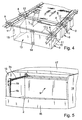
- FIG. 1 A combination passenger car according to FIGS. 1 to 3 is shown in FIG. 1 provided in a rear loading space 1 with a receiving device, the two receiving pockets in the illustrated embodiment 9 has.
- the two receiving pockets 9 each consist of a folded structure that is box-shaped when unfolded and is open to the top. Opposite long sides of each pocket 9 are each with a in their upper edge area dimensionally stable support profile (Fig. 4) 10.
- Each support profile 10 is in a hem of the folding structure, which is preferably made of flexible material 13 hammered in and so firmly anchored in it.
- each Support profile 10 extends over the entire length of the long side of the Receiving pocket 9 and protrudes with opposite holding heads 11 on opposite End faces in each case beyond the receiving pockets 9.
- the holding heads are in one piece Extensions or extensions of the support profile so that the holding heads 11 have the same cross-section as the support profiles 10.
- the folded structure 13 is thus suspended from two support profiles 10.
- the pockets 9 are with their long sides in the vehicle transverse direction aligned and suspended in such a way in a hold 3, 7, that the support profiles are horizontal and in the vehicle transverse direction extend.
- the bracket has on opposite sides of the load compartment a mounting area, which in the illustrated embodiment by one each over at least part of the length of the loading space horizontal mounting and guide rail 3 is formed.
- the receiving and guide rail 3 are several recordings 7 provided that in the illustrated embodiment as trough-like depressions, some arranged in pairs are. The depressions are in this way on the cross section of the holding heads 7 coordinated that there is a positive fit.
- bracket 12 there are two adjacent ones Support profiles 10 of two receiving pockets by one as a grouping unit appropriate bracket 12 connected together, the bracket can be designed to be elastic or inelastic.
- the bracket 12 is executed bow-shaped, as can be seen from FIG. 4, so that it can grasp two support profiles in the area of the handles 11.
- a loading space safety device 5 is additionally assigned to the receiving device, which has a horizontally extendable tarpaulin 6.
- the horizontal tarpaulin 6 runs just above the mounting areas 3 and below a vehicle curb.
- the bracket areas those on opposite sides of the cargo space 1 on the vehicle side are anchored, have on their top to lock the tarpaulin 6 breakpoints in at least one defined extension position, here in the form of hooks 8, which face each other at the opposite Bracket areas opposite each other in pairs. It are several pairs of hooks 8 over the length of the mounting areas distributed to lock the tarpaulin 6 to allow in multiple extension positions.
- the tarpaulin 6 serves to cover the upwardly open receiving pockets 9, to firstly throw objects out of the To prevent receiving pockets, and on the other hand to one To ensure privacy of the contents of the receiving pockets 9.
- FIGS. 1 to 3 or from FIGS. 5 to 7, are the mounting areas through opposite guide rails 4, 4a, 4b on the front or rear side of the loading space 1 to the loading space floor 2 led downwards.
- the guide rails 4, 4a, 4b as well as the guide rails 3 are designed such that the holding heads 11 of the mounting rails can be moved in these guide rails are arranged. Since the receiving pockets 9, as below will be described in more detail in a compact rest position collapsible, rollable or collapsible in some other way are, it is possible to the receiving pockets 9 when not in use to be placed on the front or rear of the load compartment floor 2 (Fig. 1 to 3).
- the structure of the receiving pockets 9 is good with reference to FIGS. 12 to 18 recognizable.
- the illustrated embodiments are based on two different Variants. Both variants have in common that each a folded structure of a receiving pocket 9 on two longitudinally extending Support profiles is suspended.
- the folding structure is one variant 12 is only designed in a web shape, so that one after sagging at the bottom, but to the opposite ends open fold results.
- the other variant shows in the unfolded State a cuboid shape.
- the folded structure on opposite End faces additionally with a front fold section each 15 provided the front side walls for the folded structure and the receiving bag results.
- the storage bag thus closed all around and only open at the top.
- Both variants are symmetrical to their median longitudinal plane, in the Functional position in a vertical plane, to a narrow thickness collapsible. At least the variant according to FIG. 12 is also can be rolled up because the flexible fabric is only web-shaped is trained. In the variant according to FIG. 18, it is possible to cut into the wall sections of the folded section thin, plate-like stiffeners embed to ensure the stability of the folded structure and the receiving pocket to increase.
- elastic traction means 33 are provided on the bottom, according to the stretched state of the fabric 17 and 18 exert a tensile load on the floor, so that after a brief push in the direction of folding, the folding movement is supported by the tensile forces of the tensioning means 33.
- the shelf 32 consists of two in the illustrated embodiment Parts that are either butted together or overlapping each other be put together, as with the exploded views is recognizable.
- the two shelves are on the outside 32 beveled in such a trapezoidal manner that a folding movement of the side folding sections 15 is not hindered.
- a cord 14 is assigned to the pair of receiving pockets according to FIG. 12, of the receiving pocket pair according to FIGS. 13 and 14 in a compact, folded and / or rolled rest position can constrict.
- FIGS. 15 and 16 it is also possible that on the opposite end faces laterally protruding holding heads 11 of the support profiles 10 both Receiving pockets 9 by a serving as a grouping unit Fold clip 12a together.
- the cargo-side bracket is for each Clip 12a each have a receptacle 30 in which the clip 12a can be held releasably. Securing the bracket 12a in the receptacle 30 is shown schematically in the embodiment according to FIG shown retaining spring 31 supports.
- the holding heads are Support profiles 10 of the receiving pockets 9 adapter means 20 in the form of Assigned sliding or rolling elements, each in a guide rail of the mounting area 3b are guided to be longitudinally movable.
- the Transition of the horizontal guide rails to the vertically downwards leading guide rails 4b (Fig. 5) is carried out by a baffle arrangement 19, which is shown in detail with reference to FIGS. 5 to 7.
- a guide groove is also have the guide rails 3b, 4b, in this baffle arrangement 19 continued, the guide groove following the guide rail 3b first upwards and only then vertically Is curved downwards.
- the cargo space is at the rear bounded by a transom 16 in the area of the cargo hold floor 2, by a certain amount over the load floor 2 protrudes upwards.
- the pockets can be stored in this area without the loading and unloading opening of the cargo space is affected in size by these pockets.
- the 5 to 8 represents in particular a cargo space Loading space for a notchback sedan in a rear area of this Vehicle.
- Reference numeral 17 is a schematically shown, upper limit of the cargo space referred to one Rear lid, not shown, connects to the front in the vehicle longitudinal direction.
- the loading space is delimited laterally by side walls 18. On these side walls 18, the guide rails 3b, 4b and the baffle arrangement 19 of the respective mounting area attached.
- each one upwards have open insertion groove 26.
- This insertion groove 26 is based on the 10 and 11 recognizable plug pins of each support profile 10th matched that the plug pin 25 into the plug groove 26 from above is insertable and positively held in this.
- each support profile is relative to the support profile 10 arranged longitudinally.
- the adapter means 20 in the desired pull-out position is locked to prevent it from moving relative when driving, the cylindrical extension of the adapter means 20a can slide back into the support profile 10, whereby under certain Circumstances of the plug pin 25 slide out of the plug groove 26 could.
- the fixed to the support profile 10 receiving block, in which the link pin 28 is arranged is also with a locking groove 24 provided that protrudes to the side.
- Snap hook 23 of an adjacent adapter means 20a can be snapped into place, around an adjacent support profile in a parallel one 11 position to fix. This makes it possible to have several To connect support profiles 10 of adjacent receiving pockets. If two support profiles of a single receiving pocket with each other are connected, it is inevitable through this connection the receiving opening for loading and unloading the receiving pocket is closed.
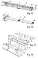
- FIG. 19 corresponds essentially the embodiments as described with reference to FIGS. 1 to 4 have been made, so that reference is made to the disclosure there.
- the only The difference is that the receiving pocket has 9 opening aids has in the form of grip tabs 34 in the region of the support profiles. hereby opening the receiving opening of the receiving pocket is facilitated.
- FIGS. 20 and 21 are the opposite Mounting areas 3c in the area of the side walls 18 of the cargo area with telescopic guide rails Mistake. A similar telescopic extensibility is also available with the Holding areas 3d according to FIG. 26 are provided.
- the bracket areas 3c according to FIGS. 20 and 21 each have a longitudinally displaceable Guide rail 36 on the one hand with recordings for individual insertion of holding heads of receiving pockets 9 provided is.
- there is also a holder for inserting a grouping unit 12a is provided, which merges several receiving pockets 9 and by means of which these receiving pockets 9 are removed in blocks can be. The removability of the group unit 12a the guide rail 36 is up through the arrow clarified.
- the cargo space of the motor vehicle according to FIGS. 20 and 21 has a hinged rear mirror on the rear, as it is in particular with loading areas of commercial or lorries open at the top is provided.
- the mounting areas 3c are arranged in such a way that the longitudinally displaceable guide rails 36 over the lowered Rearview mirror can be pulled back. This simplifies the loading and unloading of storage bags 9 allows.
- 21 is the closed position of the transom 35 and the retracted position of the bracket area 3c.
- the longitudinally displaceable mounting areas are 3d provided in a loading space of a notchback sedan.
- the mounting areas 3d here have fastened on the cargo side Guide rails 41 on which hollow profile rails can be moved are stored, to which reference numerals 3d point.
- these hollow profile rails are again telescopic rails 42 longitudinally displaceable stored so that when pulled out - as shown - a great possibility of shifting the receiving pockets 9 to the rear or forward along the double arrow.
- the two receiving pockets 9 each have a separate one outer support profile and a common inner support profile 10a, so that the two receiving pockets 9 in the area of the common Support section 10a are necessarily and firmly connected.
- 24 shows the variant of the folding structure with side folding sections on the end face shown.
- 25 is the variant with web-shaped folded structures shown, in which the receiving pockets towards the end faces is open.
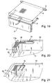
- the holder 37 to hold and secure the corresponding pockets in a recess of the cargo area floor sunk.
- the bracket 37 extends across the entire width of the load compartment floor.
- the holder 37 is designed and has a cassette-like housing guides on each of the opposite ends by means of whose the bracket 37 in vertically upward guide rails 38 is guided vertically.
- To transfer the bracket 37 In the functional position, the holder 37 is along the guide rails 38 moved up. This can be done manually or by not further shown drive means take place. In the upper functional position the bracket locked.
- bracket areas 39, 40 fold forwards or backwards by 90 °, so that both in front of the Bracket and behind the bracket two each parallel result in opposite guide rails.
- a receiving pocket according to FIGS. 27 and 28 has a two-part Insert 32 on, the two bottom parts by means of a Hinge assembly 49 are interconnected.
- the hinge arrangement is designed so that it is supported in the horizontal, level functional position by the two base parts 32 lie against one another with their adjacent edges.
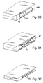
- FIGS. 29 to 32 means for inevitable folding of the receiving bag from its unfolded Functional position provided.
- outside are in the Bottom area of the receiving pocket fastened two dimensionally stable hollow profiles 45, which parallel to the illustrated embodiment Support profiles 10, but only over part of the length of the fabric extend.
- elastic bands 46 partially integrated in the hollow profiles 45, which in the unfolded functional position of the pocket in your Tension state are transferred. Due to the resulting tensile load these support the folding movement of the receiving pocket.
- FIGS. 31 and 32 are acting scissors-like elastic traction means 47 are provided, which the receiving pocket from the 31 inevitably in the folded position Transfer the rest position according to FIG. 32.
- FIGS. 33 and 34 discloses schematically Synchronization means 20b, 48 to the support profiles 10 and thus opposite Holding heads or grouping units relative to one at right angles between the opposite bracket areas 3e extending transverse axis parallel.
- the folding structure supporting support profiles 10 designed as hollow profiles are permeated by a wave. The wave protrudes to the opposite End faces beyond the end faces of the respective support profile 10.
- adapter means in the form of cracks 20b are provided in these end regions, each with a rack profile 48 in each mounting area Comb 3e.
- the opposite rack profiles 48 both mounting areas 3e designed as guide rails are identical to each other, so that when the Support profiles 10, the opposite pinion 20b due to the same Ensure the tooth pitch on both faces is the same feed.
- the support profiles 10 thus remain during their displacement movement always parallel to one between the opposite Bracket areas 3e extending transverse axis and therefore always perpendicular to the longitudinal axes of the mounting areas 3e.
- FIG. 35 corresponds essentially to the embodiment 22 essential difference is that here cassette-shaped bracket 37 is not sunk in the load floor, but rather is arranged on the cargo floor.
- height shift of the bracket 37 with the help of telescopic rods or perform differently designed height-shifting means.
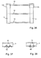
- FIG. 36 is one provided with two parallel mounting areas 3 Bracket shown in a schematic top view.
- the support profiles 10 with their holding heads direct, i.e. without merging by means of a grouping unit, in to move the guide rails.
- To a lock or fixation the support profiles 10 or the grouping units 12b in different Positions over the longitudinal extent of the holding areas 3 to enable blocking means 43, 44 in the guide rails the places where the support profiles 10 or the grouping units 12b should be locked.
- blocking means 43, 44 can have legs, springs or even rest areas with balls 44 as provided schematically with reference to FIGS. 37 and 38 are shown.
- the 39 and 40 are in the area from opposite side walls of the loading space 1 in each case Longitudinal guides 3f are provided, each with one towards the center of the loading space open guide slot 52 are provided.
- the guide slots 52 are holding heads 11 of support sections 10 held for receiving pockets that are in the longitudinal guides 3f, i.e. along the guide slots 52 are slidably disposed.
- the bracket and guidance of the holding heads 11 corresponds to that previously described Embodiments, so that this is not discussed in more detail here must become.
- the longitudinal guides 3f are as rail profiles designed, each at the same height with an open section 59 are provided. In the area of the open sections 59 the holding heads 11 and thus the support sections 10 and the receiving pockets removable upwards or from above into the longitudinal guides 3f used.
- Cover elements are used to close the open sections 58 provided that are removed or inserted by hand can.
- the cover elements 58 are with corresponding locking or Provide guide edges in corresponding locking or guide grooves of the open sections 59 are adjustable and so one secure positioning of the cover elements 58 on the longitudinal guides 3f enable.
- the cassette housing 54 held on the opposite end faces is provided with a holding head 11f.
- the holding head 11f on each end face of the cassette housing 54 is designed such that on the one hand a holder of the cassette housing 54 in the Longitudinal guides 3f allows.
- the holding heads ensure 3f a displaceability of the cassette housing 54 within the Guide slots 52 of the longitudinal guides 3f.
- the cassette housing assigned a locking device 57 which is designed to be manually releasable and blocking the longitudinal displaceability of the cassette housing 54 guaranteed in the guide slots 52.
- the locking device 57 points in an unrecognizable way in the area at least one holding head 11f on a braking element which is a form or non-positive fixation of the holding head 11f in the respective Guide slot 52 achieved.
- By pressing an operating button on the Locking device 57 is the braking or blocking effect of the braking element canceled, whereby the cassette housing 54 slidably is.
- the cassette housing 54 can - as can be seen from FIG. 40 is - moved up to the open sections 59 and on this Be removed upwards. In the same way, the cassette housing 54 in the area of the open sections 59 again be inserted into the guide slots 52 from above.
- the longitudinal guides 3f taper and form slot guides 53. These are for receiving lateral guide elements 56 of a contour part a cargo space cover 55 is provided which is a flexible sheet represents.
- the flexible fabric is no closer to one shown winding shaft held within the cassette housing and arranged relative to this can be wound up or unwound.
- the load compartment cover 55 itself can also cross with the direction of extension running, at equal intervals over the length of the fabric distributed support rods may be provided in the Guide slots 52 of the longitudinal guides 3f can be held.
- the height of the guide slots 52 can preferably be such that that the support rods with their ends above the holding heads 11 of the Receiving pockets in the guide slots 52 are passed can.
- the slot guides 53 serve the contour part of the load compartment cover 55 by means of the guide elements 56 in the stretched covering position to fix in the rear area of the cargo area 1.
- locking elements in both slot guides 53 provided both securing the load compartment cover 55 in the open state as well as a release for a return allow to the rest position.
- the slot guides 53 are wider than the guide slots 52 arranged offset to the center of the cargo area.
- the guide elements 56 with respect to the holding heads 11 or 11f arranged offset to the center of the loading space.
- the guide elements 56 opposite the holding heads 11 or 11f positioned offset to the center of the cargo area.
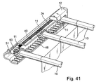
- each grouping unit 12 has 12 guide sections in the inserted state the grouping unit 12 with a guide slot of the longitudinal guide 3e s worn.
- the guide section provided with a tooth structure, which is a continuation a tooth structure of the guide slot of the longitudinal guide 3e.
- the tooth structure serves as a synchronization means 48 for parallel alignment of the support rods 10 for the receiving pocket.
- the grouping unit 12 is fixed in FIG. 41 in FIG Extension of the longitudinal guide 3e positioned or in a corresponding open section of the longitudinal guide 3e or a corresponding Recess arranged.
- the grouping unit 12 can can be released and removed from this position. At the same time it can take up all the support rods 10 of the receiving pockets so that the grouping unit 12 on each side of the pockets with the pockets can be removed.
- a return device 49 to 51 is provided.
- the return device has a return spring 49 on one with the foremost support rod 10 of the pair of receiving pockets attacking adapter piece 50 attached is. With its opposite end is the return spring 49 held on the grouping unit 12.
- the adapter piece 50 is in a longitudinal groove section of the longitudinal guide 3e parallel to the guide slot slidably guided.
- the adapter piece 50 is a manually operated one Locking device 51 associated with the adapter piece 50 either locks or for a return movement by the return spring 49 releases.
- the locking device 51 has a manually operable Control button on, the movement of which is blocking or releasing of the adapter piece 50 controls.
- the adapter piece 50 is preferably designed as a damper to the initiated by the return spring 49 Slow down, slow down or dampen the return movement.
- the adapter piece 50 is designed so that it fits into the Longitudinal groove section of a return movement non-positively a certain Brings resistance, which achieves the damping effect becomes.
Landscapes
- Engineering & Computer Science (AREA)
- Mechanical Engineering (AREA)
- Vehicle Step Arrangements And Article Storage (AREA)
Abstract
Description
- Fig. 1
- zeigt schematisch in einer teilweise aufgeschnittenen Seitenansicht einen in einem heckseitigen Laderaum eines KombiPersonenkraftwagens angeordnete Ausführungsform einer erfindungsgemäßen Aufnahmevorrichtung,
- Fig. 2
- eine Darstellung ähnlich Fig. 1 mit einer modifizierten Aufnahmevorrichtung,
- Fig. 3
- eine Darstellung ähnlich den Fig. 1 oder 2 mit einer modifizierten Aufnahmevorrichtung,
- Fig. 4
- in vergrößerter, perspektivischer Darstellung eine Aufnahmevorrichtung gemäß Fig. 1 oder 3,
- Fig. 5
- schematisch einen Laderaum eines Kraftfahrzeuges mit einer weiteren Ausführungsform einer erfindungsgemäßen Aufnahmevorrichtung,
- Fig. 6
- den Laderaum nach Fig. 5 in einer anderen Perspektive,
- Fig. 7
- in vergrößerter perspektivischer Darstellung einen Ausschnitt der Aufnahmevorrichtung nach Fig. 6,
- Fig. 8
- in vergrößerter perspektivischer Darstellung einen weiteren Ausschnitt der Aufnahmevorrichtung nach Fig. 5,
- Fig. 9
- in perspektivischer Darstellung einen Laderaum mit einer weiteren Ausführungsform einer erfindungsgemäßen Aufnahmevorrichtung, wobei aus Übersichtlichkeitsgründen eine linke Hälfte der Aufnahmevorrichtung dargestellt ist,
- Fig. 10
- in vergrößerter, perspektivischer Explosionsdarstellung einen mit einem Adaptermittel für einen Haltekopf versehenen Stützabschnitt, der in einer fahrzeugfesten Aufnahme fixierbar ist,
- Fig. 11
- zwei benachbarte Stützabschnitte gemäß Fig. 10 in zusammengefügter Halteposition,
- Fig. 12
- zwei Aufnahmetaschen, deren Stützprofile durch elastische Fixiermittel derart miteinander verbunden sind, dass sich ein Aufnahmetaschenpaar ergibt,
- Fig. 13
- das Aufnahmetaschenpaar nach Fig. 12 in einer zusammengelegten Zwischenposition,
- Fig. 14
- das Aufnahmetaschenpaar nach den Fig. 12 und 13 in der fest verschnürten und zusammengerollten Ruheposition,
- Fig. 15
- das Aufnahmetaschenpaar nach Fig. 12, dessen Stützprofile im Bereich ihrer Halteköpfe mit als Gruppierungseinheiten dienenden Klammmern umgebbar sind,
- Fig. 16
- das Aufnahmetaschenpaar nach Fig. 15 in der zusammengeschnürten Ruheposition, wobei die klammerförmige Gruppierungseinheit in einem entsprechenden Aufnahmebereich des seitlichen Halterungsbereiches lösbar fixiert ist,
- Fig. 17
- in perspektivischer Explosionsdarstellung eine Ausführungsform einer Aufnahmetasche mit stirnseitigen Seitenfaltabschnitten sowie mit einem zweigeteilten Einlegeboden,
- Fig. 18
- die Aufnahmetasche nach Fig. 17 in ihrer umgedrehten, den Boden nach oben weisenden Position,
- Fig. 19
- in perspektivischer Darstellung eine Ausführungsform einer erfindungsgemäßen Aufnahmevorrichtung, die durch eine horizontale Abdeckplane eines Abdeckrollos überdeckbar ist,
- Fig. 20
- eine weitere Ausführungsform einer Aufnahmevorrichtung, bei der die seitlichen Halterungsbereiche mit ausziehbaren Längsführungen versehen sind, in denen mehrere Aufnahmetaschen mit stirnseitigen Halteköpfen oder mit korrespondierenden Adaptermitteln fixierbar sind,
- Fig. 21
- die Ausführungsform nach Fig. 20, wobei die Längsführung in der eingeschobenen Stauposition dargestellt ist,
- Fig. 22
- schematisch eine weitere Ausführungsform einer erfindungsgemäßen Aufnahmevorrichtung in einem Kofferraum eines Personenkraftwagens,
- Fig. 23
- die Aufnahmevorrichtung nach Fig. 22 in ihrer Funktionsposition,
- Fig. 24
- eine Darstellung eines Aufnahmetaschenpaares mit einem mittleren, gemeinsamen Stützabschnitt,
- Fig. 25
- eine weitere Ausführungsform eines Aufnahmetaschenpaares, wobei die Falten seitlich offen sind,
- Fig. 26
- eine weitere Ausführungsform einer erfindungsgemäßen Aufnahmevorrichtung mit teleskopförmig ausziehbaren Längsführungen an den seitlichen Halterungsbereichen für wenigstens eine Aufnahmetasche,
- Fig. 27
- schematisch in perspektivischer Explosionsdarstellung eine Ausführungsform einer Aufnahmetasche mit versteiftem Einlegeboden,
- Fig. 28
- in vergrößerter, schematischer Darstellung einen Ausschnitt des Einlegebodens nach Fig. 27,
- Fig. 29
- eine weitere Ausführungsform einer Falttasche mit im Bodenbereich angeordneten Hohlprofilen,
- Fig. 30
- einen Ausschnitt der Falttasche nach Fig. 29, wobei in die Hohlprofile elastische Zugmittel eingezogen sind,
- Fig. 31
- eine weitere Ausführungsform einer Falttasche ähnlich Fig. 29 und 30, wobei scherenartige Zugmittel zum Zusammenfalten der Aufnahmetasche vorgesehen sind,
- Fig. 33
- schematisch eine Darstellung einer aus zwei als Führungsschienen gestalteten Halterungsbereichen zusammengesetzten Halterung für ein längsbewegliches Stützprofil,
- Fig. 34
- schematisch in einer Seitenansicht die Ausführung nach Fig. 33,
- Fig. 35
- in schematisierter Darstellung eine Ausführung einer Aufnahmevorrichtung ähnlich Fig. 22,
- Fig. 36
- in einer Draufsicht schematisch eine Ausführungsform einer Aufnahmevorrichtung mit mehreren Arretierpositionen für die Stützprofile,
- Fig. 37
- in vergrößerter Schnittdarstellung ein Stützprofil im Bereich von Blockiermitteln der Halterung,
- Fig. 38
- eine Darstellung ähnlich Fig. 37 mit modifizierten Blockiermitteln,
- Fig. 39
- in perspektivischer Darstellung eine weitere Ausführungsform einer Aufnahmevorrichtung mit einem verschiebbarem Kassettengehäuse,
- Fig. 40
- die Aufnahmevorrichtung nach Fig. 39 in einer Entnahmeposition des Kassettengehäuses und
- Fig. 41
- in vergrößerter, schematischer Darstellung eine Ausführungsform ähnlich der Fig. 33 oder 36, bei der den Halteköpfen eine Antriebsvorrichtung in Form einer Rückholfeder zugeordnet ist.
Claims (32)
- Aufnahmevorrichtung für einen Laderaum eines Kraftfahrzeugs mit wenigstens einer zumindest abschnittsweise flexiblen Aufnahmetasche, die laderaumfest fixierbar ist, dadurch gekennzeichnet, dass zwei gegenüberliegende Seiten der Aufnahmetasche (9) jeweils einen formstabilen, sich über wenigstens die Länge der zugeordneten Seite erstreckenden Stützabschnitt (10) aufweisen, wobei die Stützabschnitte (10) mit ihren gegenüberliegenden Stirnbereichen in einer laderaumseitigen Halterung (3 bis 3d) lösbar fixierbar sind, und dass die formstabilen Stützabschnitte (10) durch ein sich wenigstens in einem Bodenbereich der Aufnahmetasche (9) erstreckendes, flexibles Faltgebilde (13) miteinander verbunden sind.
- Aufnahmevorrichtung nach Anspruch 1, dadurch gekennzeichnet, dass wenigstens zwei parallel zueinander ausgerichtete Aufnahmetaschen (9) vorgesehen sind.
- Aufnahmevorrichtung nach Anspruch 2, dadurch gekennzeichnet, dass die beiden Aufnahmetaschen (9) mittels eines gemeinsamen Stützabschnittes (10a) miteinander in Verbindung stehen.
- Aufnahmevorrichtung nach Anspruch 1, dadurch gekennzeichnet, dass die Stützabschnitte (10) und das Faltgebilde (13) in ihrer Funktionsposition derart angeordnet sind, dass die Aufnahmetasche (9) symmetrisch zu ihrer Mittellängsebene auf- oder zufaltbar ist.
- Aufnahmevorrichtung nach Anspruch 4, dadurch gekennzeichnet, dass Mittel (29, 33) zum zwangsläufigen Auf- oder Zufalten der Aufnahmetasche vorgesehen sind.
- Aufnahmevorrichtung nach Anspruch 5, dadurch gekennzeichnet, dass als Mittel zum zwangsläufigen Auf- oder Zufalten elastische Zug- oder Druckelemente im Bereich der Stützabschnitte angreifen.
- Aufnahmevorrichtung nach Anspruch 6, dadurch gekennzeichnet, dass die elastischen Zug- oder Druckelemente zumindest teilweise in Hohlprofilen (45), insbesondere im Bereich der Stützabschnitte, integriert sind.
- Aufnahmevorrichtung nach Anspruch 1, dadurch gekennzeichnet, dass Fixiermittel (14) zum Sichern der Aufnahmetasche (9) in einem kompakten Ruhezustand vorgesehen sind.
- Aufnahmevorrichtung nach Anspruch 1, dadurch gekennzeichnet, dass das Faltgebilde als bahnförmige Falte zwischen zwei als Stützabschnitte dienenden Stützprofilen (10) verläuft.
- Aufnahmevorrichtung nach Anspruch 1, dadurch gekennzeichnet, dass das Faltgebilde an gegenüberliegenden Stirnrandbereichen mit Seitenfaltabschnitten (15) versehen ist, die Stirnseitenwände für die Aufnahmetasche (9) darstellen.
- Aufnahmevorrichtung nach Anspruch 10, dadurch gekennzeichnet, dass für einen Bodenbereich des Faltgebildes wenigstens ein zumindest weitgehend formstabiler, insbesondere geteilter Einlegeboden (32) vorgesehen ist.
- Aufnahmevorrichtung nach Anspruch 1, dadurch gekennzeichnet, dass die gegenüberliegenden Stirnbereiche des Stützabschnittes (10) als jeweils seitlich nach aussen abragende Halteköpfe (11) gestaltet sind.
- Aufnahmevorrichtung nach Anspruch 12, dadurch gekennzeichnet, dass die Halterung (3 bis 3d) zur Fixierung der Halteköpfe (11) korrespondierende Aufnahmen (7) aufweist.
- Aufnahmevorrichtung nach Anspruch 12, dadurch gekennzeichnet, dass mehrere Halteköpfe (11) auf jeder Seite mittels einer Gruppierungseinheit (12, 12a) trennbar zusammengefasst sind, die jeweils lösbar mit der Halterung (3) verbindbar ist.
- Aufnahmevorrichtung nach Anspruch 1, dadurch gekennzeichnet, dass die Halterung zwei Halterungsbereiche aufweist, die die wenigstens eine Aufnahmetasche (9) auf gegenüberliegenden Seiten flankieren.
- Aufnahmevorrichtung nach Anspruch 15, dadurch gekennzeichnet, dass jeder Halterungsbereich mit einer im Laderaum zumindest abschnittsweise parallel zu einem Laderaumboden (2) ausgerichteten Längsführung (3, 3a, 3b, 3c, 3d, 3f) versehen ist, die eine Verschiebbarkeit der Halteköpfe oder der jeweiligen Gruppierungseinheit (12, 12a) ermöglicht.
- Aufnahmevorrichtung nach Anspruch 16, dadurch gekennzeichnet, dass die beiden Längsführungen (3e, 3f) korrespondierende offene Teilabschnitte (59) aufweisen, die derart dimensioniert sind, dass ein zugehöriger Haltekopf (11, 11f) oder eine Gruppierungseinheit (12) auf Höhe des jeweiligen Teilabschnittes entnehmbar oder einsetzbar ist.
- Aufnahmevorrichtung nach Anspruch 17, dadurch gekennzeichnet, dass jede Gruppierungseinheit (12) mit einem Führungsabschnitt versehen ist, der in eingesetztem Zustand der Gruppierungseinheit mit der korrespondierenden Längsführung (3e) fluchtet.
- Aufnahmevorrichtung nach Anspruch 17, dadurch gekennzeichnet, dass ein Gehäuse (54) zur Aufnahme wenigstens eines flexiblen Flächengebildes (55) vorgesehen ist, das sich quer zwischen den Längsführungen (3f) erstreckt und im Bereich gegenüberliegender Stirnseiten mit Halteköpfen (11f) versehen ist, die in den Längsführungen (3f) verschiebbar angeordnet sind.
- Aufnahmevorrichtung nach Anspruch 19, dadurch gekennzeichnet, dass das Gehäuse (54) eine Arretiereinrichtung (57) aufweist, die das Gehäuse in den Längsführungen (3f) lösbar blockiert.
- Aufnahmevorrichtung nach Anspruch 16, dadurch gekennzeichnet, dass die Längsführung (3d, 36, 42) in Verlängerung des Halterungsbereiches ausziehbar gestaltet ist.
- Aufnahmevorrichtung nach Anspruch 21, dadurch gekennzeichnet, dass Blockiermittel (43, 44) zum Arretieren der Längsführung und/oder der Gruppierungseinheit vorgesehen sind.
- Aufnahmevorrichtung nach Anspruch 14, dadurch gekennzeichnet, dass Antriebsmittel zur Verlagerung der Halteköpfe oder der Gruppierungseinheiten innerhalb der Längsführungen vorgesehen sind.
- Aufnahmevorrichtung nach Anspruch 16, dadurch gekennzeichnet, dass die Längsführungen (4, 4a, 4b) in einem vorderen und/oder einem hinteren Endbereich zu dem Laderaumboden (2) hin nach unten geführt sind.
- Aufnahmevorrichtung nach Anspruch 12, dadurch gekennzeichnet, dass die Halteköpfe mit Hilfe von Adaptermitteln (20, 20a) lösbar mit den Halterungsbereichen, den Längsführungen oder den Gruppierungseinheiten in Verbindung stehen.
- Aufnahmevorrichtung nach Anspruch 25, dadurch gekennzeichnet, dass benachbarte Adaptermittel durch formschlüssig wirksame Rastmittel (23, 24) lösbar aneinanderfügbar sind.
- Aufnahmevorrichtung nach Anspruch 26, dadurch gekennzeichnet, dass die Rastmittel einstückig an den Adaptermitteln (20, 20a) angeformt sind.
- Aufnahmevorrichtung nach Anspruch 1, dadurch gekennzeichnet, dass die Halterung (37) innerhalb des Laderaums zwischen einer insbesondere in einem Laderaumboden oder in einer Wandbegrenzung versenkten Ruheposition und einer Funktionsposition beweglich gelagert ist.
- Aufnahmevorrichtung nach Anspruch 28, dadurch gekennzeichnet, dass die Halterung wenigstens zwei beweglich angeordnete Halterungsbereiche (39, 40) aufweist, die aus einer in der Halterung (37) zusammengeführten Ruhelage in eine zueinander beabstandete und wenigstens eine Aufnahmetasche zwischen den Halterungsbereichen aufnehmende Funktionslage überführbar sind.
- Aufnahmevorrichtung nach Anspruch 29, dadurch gekennzeichnet, dass die Halterungsbereiche horizontal schwenkbeweglich angeordnet sind.
- Aufnahmevorrichtung nach Anspruch 1, dadurch gekennzeichnet, dass der Aufnahmevorrichtung ein horizontal ausziehbares Abdeckgebilde (6) zugeordnet ist, das die wenigstens eine Aufnahmetasche (9) in wenigstens einer Ausziehposition überdeckt.
- Aufnahmevorrichtung nach Anspruch 16, dadurch gekennzeichnet, dass Synchronisierungsmittel (20b, 48) vorgesehen sind, die eine Parallelverlagerung der gegenüberliegenden Halteköpfe oder Gruppierungseinheiten wenigstens einer Aufnahmetasche relativ zu einer rechtwinklig zwischen den gegenüberliegenden Halterungsbereichen verlaufenden Querachse durchführen.
Applications Claiming Priority (2)
| Application Number | Priority Date | Filing Date | Title |
|---|---|---|---|
| US35370402P | 2002-01-31 | 2002-01-31 | |
| US353704P | 2002-01-31 |
Publications (3)
| Publication Number | Publication Date |
|---|---|
| EP1332919A2 true EP1332919A2 (de) | 2003-08-06 |
| EP1332919A3 EP1332919A3 (de) | 2003-12-10 |
| EP1332919B1 EP1332919B1 (de) | 2007-10-31 |
Family
ID=23390209
Family Applications (1)
| Application Number | Title | Priority Date | Filing Date |
|---|---|---|---|
| EP03001418A Expired - Lifetime EP1332919B1 (de) | 2002-01-31 | 2003-01-22 | Aufnahmevorrichtung für einen Laderaum eines Kraftfahrzeugs |
Country Status (5)
| Country | Link |
|---|---|
| US (1) | US7028872B2 (de) |
| EP (1) | EP1332919B1 (de) |
| JP (1) | JP2003226194A (de) |
| KR (1) | KR20030066377A (de) |
| DE (1) | DE50308477D1 (de) |
Cited By (15)
| Publication number | Priority date | Publication date | Assignee | Title |
|---|---|---|---|---|
| EP1574394A1 (de) * | 2004-02-18 | 2005-09-14 | BOS GmbH & Co. KG | Funktionseinheit für einen Fahrzeuginnenraum |
| DE102004021556A1 (de) * | 2004-05-03 | 2005-12-01 | Daimlerchrysler Ag | System zum Abdecken und Abteilen des Laderaumes in Personenkraftwagen, insbesondere Kombifahrzeugen |
| DE102004032246A1 (de) * | 2004-07-03 | 2006-01-19 | Bayerische Motoren Werke Ag | Kraftfahrzeug mit einer zweiten und einer dritten Sitzreihe |
| DE102005011678A1 (de) * | 2005-03-11 | 2006-09-21 | Webasto Ag | Aufnahmeeinrichtung sowie Kraftfahrzeug mit einer Aufnahmeeinrichtung |
| EP1834837A1 (de) * | 2006-03-15 | 2007-09-19 | BOS GmbH & Co. KG | Staubehältnis für den Einsatz in einem Laderaum |
| DE102007011055A1 (de) * | 2007-03-07 | 2008-09-11 | GM Global Technology Operations, Inc., Detroit | Aufnahmevorrichtung |
| US7931177B2 (en) | 2007-08-14 | 2011-04-26 | Bos Gmbh & Co. Kg | Storage container for use in a boot |
| US7934761B2 (en) | 2007-11-26 | 2011-05-03 | Bos Gmbh & Co. Kg | Storage compartment with a supporting frame, and receiving device for a supporting frame |
| EP2574505A1 (de) * | 2011-09-30 | 2013-04-03 | Skoda Auto a.s. | Ablagebox des Laderaums von Fahrzeugen |
| EP3075601A1 (de) * | 2015-03-30 | 2016-10-05 | Toyota Boshoku Kabushiki Kaisha | Layoutsystem für laderaum eines fahrzeugs |
| WO2021204307A1 (de) * | 2020-04-06 | 2021-10-14 | Skoda Auto, A.S. | Verschiebbare aufnahmetasche im kofferraum eines kraftfahrzeuges |
| CZ309757B6 (cs) * | 2020-04-06 | 2023-09-20 | ŠKODA AUTO a.s. | Posuvný odkládací vak zavazadlového prostoru |
| DE102018216151B4 (de) | 2018-04-12 | 2024-06-20 | Hyundai Motor Company | Fahrzeug-Gepäckraumabdeckvorrichtung |
| DE102023208387A1 (de) * | 2023-08-31 | 2025-03-06 | Volkswagen Aktiengesellschaft | Laderaumunterteilung für ein Fahrzeug |
| DE102020125595B4 (de) | 2019-10-23 | 2026-01-15 | GM Global Technology Operations LLC | Rekonfigurierbare Ablageanordnung für ein Fahrzeug |
Families Citing this family (51)
| Publication number | Priority date | Publication date | Assignee | Title |
|---|---|---|---|---|
| US20050145661A1 (en) * | 2004-01-02 | 2005-07-07 | Lear Corporation | Suspended storage system |
| US7066516B2 (en) * | 2004-03-31 | 2006-06-27 | Lear Corporation | Rear vehicle storage system |
| US7118152B2 (en) * | 2004-05-07 | 2006-10-10 | Ford Global Technologies, Llc | Automotive cargo restraint and security screen |
| US20060180623A1 (en) * | 2005-02-11 | 2006-08-17 | Reynolds Brian J | Rear vehicle storage system |
| US7214018B2 (en) * | 2005-03-31 | 2007-05-08 | Nissan Technical Center North America, Inc. | Sliding bed accessory arrangement |
| DE102005026671A1 (de) * | 2005-06-01 | 2006-12-07 | Bos Gmbh & Co. Kg | Stauvorrichtung für einen Fahrzeugkofferraum |
| DE102005031072A1 (de) * | 2005-06-24 | 2007-01-04 | Bos Gmbh & Co. Kg | Laderaumfunktionsvorrichtung für ein Kraftfahrzeug |
| DE102005031070B4 (de) * | 2005-06-24 | 2012-02-23 | Bos Gmbh & Co. Kg | Laderaumfunktionsvorrichtung für ein Kraftfahrzeug |
| EP1787864B1 (de) * | 2005-11-22 | 2009-03-25 | Mazda Motor Corporation | Hintere Struktur eines Kraftfahrzeugs |
| US20070296258A1 (en) * | 2006-06-23 | 2007-12-27 | Kyle Calvert | Rear seat extended fold and kneel reconfiguration |
| US20080145172A1 (en) * | 2006-12-18 | 2008-06-19 | Lear Corporation | Vehicle cargo retainer |
| US20080142560A1 (en) * | 2006-12-19 | 2008-06-19 | Lim Stephen T | Grocery bag bar and holding system |
| US8672016B2 (en) * | 2007-01-10 | 2014-03-18 | Irvin Automotive Products, Inc. | Folding end cap |
| US7779887B2 (en) * | 2007-01-10 | 2010-08-24 | Irvin Automotive Products, Inc. | Rotating end cap |
| US7591296B2 (en) * | 2007-10-17 | 2009-09-22 | Irvin Automotive Products, Inc. | Two piece removable end cap |
| US7806453B2 (en) * | 2008-01-02 | 2010-10-05 | Honda Motor Co., Ltd. | Stowable cover with storage feature for vehicle cargo area and method |
| US7874606B2 (en) * | 2008-01-22 | 2011-01-25 | Yamaha Hatsudoki Kabushiki Kaisha | Utility vehicle |
| US7644972B2 (en) * | 2008-01-31 | 2010-01-12 | Chrysler Group Llc | Grocery bag holder integrated with a Tonneau cover feature |
| DE102009039476A1 (de) * | 2009-08-31 | 2011-03-03 | GM Global Technology Operations, Inc., Detroit | Kraftfahrzeug mit einer Haltevorrichtung zur Fixierung einer Einkaufswagentasche |
| DE102012013013A1 (de) * | 2012-06-29 | 2014-01-02 | Volkswagen Aktiengesellschaft | Ablagevorrichtung für den Gepäckraum eines Fahrzeugs |
| DE102013005535A1 (de) * | 2013-03-30 | 2014-10-02 | Daimler Ag | Behältnis, insbesondere zum Einbauen in eine Heckklappe eines Kraftfahrzeugs |
| US9114734B2 (en) | 2013-06-17 | 2015-08-25 | Mervyn G. Hackney | Collection bin for automobile seat pocket |
| US20150360621A1 (en) * | 2014-06-14 | 2015-12-17 | Furious Innovation, LLC. | Cargo mat system |
| US9340143B2 (en) | 2014-08-27 | 2016-05-17 | Ford Global Technologies, Llc | Adjustable cargo track system on side panel |
| US9440590B1 (en) * | 2015-04-09 | 2016-09-13 | Ford Global Technologies, Llc | Cargo shade storage pocket with hidden storage |
| US9527451B2 (en) * | 2015-05-08 | 2016-12-27 | Ford Global Technologies, Llc | Retractable cargo cover with integral storage compartment |
| US10202081B2 (en) * | 2015-09-30 | 2019-02-12 | Ford Global Technologies, Llc | Package tray assembly including hidden expandable storage system |
| DE102015220192B3 (de) * | 2015-10-16 | 2017-03-09 | Bos Gmbh & Co. Kg | Schutzvorrichtung für einen Laderaum eines Kraftfahrzeugs |
| US20170129548A1 (en) * | 2015-11-06 | 2017-05-11 | Ford Global Technologies, Llc | Easily accessible and foldable storage unit for a pickup bed |
| JP6154949B1 (ja) * | 2016-08-04 | 2017-06-28 | 吉田化学株式会社 | 固定装置 |
| CN106740520B (zh) * | 2017-03-14 | 2023-03-10 | 广东东箭汽车科技股份有限公司 | 一种汽车载物装置 |
| US20180354425A1 (en) * | 2017-06-13 | 2018-12-13 | Ford Global Technologies, Llc | Vehicle trunk |
| US10773651B2 (en) * | 2017-07-05 | 2020-09-15 | Ford Global Technologies, Llc | Convertible thermal container for a vehicle storage area |
| US20190084485A1 (en) * | 2017-09-15 | 2019-03-21 | Ford Global Technologies, Llc | Cargo compartment storage device |
| US10899284B2 (en) * | 2018-07-19 | 2021-01-26 | Timothy J Descoteaux | Vehicle mounted foldable carrying system |
| US11834005B2 (en) | 2018-08-28 | 2023-12-05 | Abc Technologies Inc. | Cargo containment systems |
| DE102018215537A1 (de) * | 2018-09-12 | 2020-03-12 | Brose Fahrzeugteile Gmbh & Co. Kommanditgesellschaft, Coburg | Vorrichtung für ein Kraftfahrzeug |
| US20200172016A1 (en) * | 2018-11-30 | 2020-06-04 | GM Global Technology Operations LLC | Multifunctional cargo sling/shelf |
| DE102018132163A1 (de) | 2018-12-13 | 2020-06-18 | Bayerische Motoren Werke Aktiengesellschaft | Ablagevorrichtung und Fahrzeug |
| DE102018132164B4 (de) | 2018-12-13 | 2026-04-23 | Bayerische Motoren Werke Aktiengesellschaft | Ablagevorrichtung und Fahrzeug |
| DE102018132165B4 (de) * | 2018-12-13 | 2026-05-07 | Bayerische Motoren Werke Aktiengesellschaft | Ablagevorrichtung und Fahrzeug |
| US11479180B2 (en) * | 2019-01-11 | 2022-10-25 | Abc Technologies Inc. | Expandable cargo box assembly for a pickup truck |
| CN110077700A (zh) * | 2019-03-12 | 2019-08-02 | 武义圣理汽车用品有限公司 | 一种多功能汽车收纳箱 |
| US11208046B2 (en) | 2019-04-08 | 2021-12-28 | Karma Automotive Llc | Vehicle cargo loading system |
| EP3962780A4 (de) * | 2019-04-30 | 2023-01-18 | Maxiloda Limited | Vorrichtungen und systeme zum stapeln von ladungen |
| US11618508B2 (en) * | 2020-12-16 | 2023-04-04 | Tim Dexter | Vehicle cargo management system |
| CN112896336A (zh) * | 2021-01-18 | 2021-06-04 | 温州天茂汽车零部件有限公司 | 一种皮卡车货箱储物车兜 |
| US11897424B2 (en) | 2021-05-07 | 2024-02-13 | Abc Technologies Inc. | Front trunk storage system |
| US11623502B1 (en) | 2021-09-30 | 2023-04-11 | Toyota Motor Engineering & Manufacturing North America, Inc. | Truck bed covers including cargo management systems |
| US11897375B2 (en) * | 2022-01-27 | 2024-02-13 | Honda Motor Co., Ltd. | Removable and stowable vehicle seat system |
| DE202022104592U1 (de) * | 2022-08-12 | 2023-09-20 | Michael Güldner | Schienensystem für deckenseitige Lagerung in Wohnmobilstauräumen |
Family Cites Families (24)
| Publication number | Priority date | Publication date | Assignee | Title |
|---|---|---|---|---|
| USRE26299E (en) * | 1967-11-21 | Collapsible storage pouch | ||
| US526249A (en) * | 1894-09-18 | Package | ||
| DE7303614U (de) * | 1973-05-03 | Adam Wolf | Kofferraum Gepacknetz fur Kraftfahr zeuge | |
| US1505182A (en) * | 1922-06-22 | 1924-08-19 | Ernest E Wrixton | Vehicle package carrier |
| US1527056A (en) * | 1924-03-17 | 1925-02-17 | Martin Mattie | Shopping bag or parcel holder |
| US2079592A (en) * | 1935-05-02 | 1937-05-11 | Pauline N Battin | Garbage receptacle |
| US2421221A (en) * | 1946-08-02 | 1947-05-27 | Walter F Rothe | Letter box |
| US2778553A (en) * | 1955-10-26 | 1957-01-22 | Satrom Company Inc | Refuse bag for automobiles |
| US2925172A (en) * | 1958-05-28 | 1960-02-16 | Victor A Hopp | Automobile trash receptacle |
| US3986656A (en) * | 1976-02-23 | 1976-10-19 | Robert H. Dickinson | Collapsible package-holding structure |
| US4979705A (en) * | 1989-03-27 | 1990-12-25 | Ralph Bovitz | Laundry bags and frame apparatus |
| DE4016708C2 (de) * | 1990-05-24 | 1994-07-21 | Baumeister & Ostler Gmbh Co | Abdeckung für den Laderaum eines PKW |
| US5628442A (en) * | 1992-03-04 | 1997-05-13 | Wayne; Mark | Package-retaining accessory for vehicle cargo area |
| US5234116A (en) * | 1992-06-15 | 1993-08-10 | Bjarni Kristinsson | Trunk securement means for grocery bags and packages |
| US5368210A (en) * | 1992-08-11 | 1994-11-29 | Wotring; Randall C. | Cargo storage apparatus |
| US5366124A (en) * | 1993-08-09 | 1994-11-22 | Dearborn Iv Arthur G | Vehicle bed load container and stabilizer |
| US5520316A (en) * | 1995-01-31 | 1996-05-28 | Chen; Shu F. | Storage rack for automobile trunks |
| GB9515295D0 (en) * | 1995-07-26 | 1995-09-20 | Roberts Christopher C | Exandable storage device |
| SE507379C3 (sv) * | 1996-09-02 | 1998-06-29 | Volvo Ab | Anordning foer saekring av last |
| US5713502A (en) * | 1996-10-15 | 1998-02-03 | Dixon; Ernestine | Collapsible trunk spacer apparatus |
| USD404861S (en) * | 1998-01-09 | 1999-01-26 | Seymour Housewares Corporation | Laundry sorter |
| JPH11314549A (ja) * | 1998-05-07 | 1999-11-16 | Nissan Motor Co Ltd | 車両の物入れ構造 |
| US6609744B2 (en) * | 2000-06-29 | 2003-08-26 | Collins & Aikman Products Co. | Collapsible storage apparatus for vehicle cargo compartments |
| DE20115063U1 (de) * | 2001-09-12 | 2002-01-24 | Wang, Wen-Tsan, Taipeh/T'ai-pei | Zusammenlegbares Regal |
-
2003
- 2003-01-22 EP EP03001418A patent/EP1332919B1/de not_active Expired - Lifetime
- 2003-01-22 DE DE50308477T patent/DE50308477D1/de not_active Expired - Lifetime
- 2003-01-29 KR KR10-2003-0005959A patent/KR20030066377A/ko not_active Withdrawn
- 2003-01-29 JP JP2003020537A patent/JP2003226194A/ja active Pending
- 2003-01-30 US US10/354,444 patent/US7028872B2/en not_active Expired - Fee Related
Non-Patent Citations (1)
| Title |
|---|
| None |
Cited By (21)
| Publication number | Priority date | Publication date | Assignee | Title |
|---|---|---|---|---|
| CN1657343B (zh) * | 2004-02-18 | 2011-06-22 | 博斯股份有限两合公司 | 汽车客舱用的功能单元 |
| EP1574394A1 (de) * | 2004-02-18 | 2005-09-14 | BOS GmbH & Co. KG | Funktionseinheit für einen Fahrzeuginnenraum |
| US7445262B2 (en) | 2004-02-18 | 2008-11-04 | Bos Gmbh & Co. Kg | Functional unit for a vehicle interior |
| US7628437B2 (en) | 2004-02-18 | 2009-12-08 | Bos Gmbh & Co. Kg | Functional unit for a vehicle interior |
| DE102004021556A1 (de) * | 2004-05-03 | 2005-12-01 | Daimlerchrysler Ag | System zum Abdecken und Abteilen des Laderaumes in Personenkraftwagen, insbesondere Kombifahrzeugen |
| DE102004032246A1 (de) * | 2004-07-03 | 2006-01-19 | Bayerische Motoren Werke Ag | Kraftfahrzeug mit einer zweiten und einer dritten Sitzreihe |
| DE102004032246B4 (de) * | 2004-07-03 | 2016-07-07 | Bayerische Motoren Werke Aktiengesellschaft | Kraftfahrzeug mit einer zweiten und einer dritten Sitzreihe |
| DE102005011678A1 (de) * | 2005-03-11 | 2006-09-21 | Webasto Ag | Aufnahmeeinrichtung sowie Kraftfahrzeug mit einer Aufnahmeeinrichtung |
| EP1834837A1 (de) * | 2006-03-15 | 2007-09-19 | BOS GmbH & Co. KG | Staubehältnis für den Einsatz in einem Laderaum |
| DE102007011055A1 (de) * | 2007-03-07 | 2008-09-11 | GM Global Technology Operations, Inc., Detroit | Aufnahmevorrichtung |
| US7931177B2 (en) | 2007-08-14 | 2011-04-26 | Bos Gmbh & Co. Kg | Storage container for use in a boot |
| US7934761B2 (en) | 2007-11-26 | 2011-05-03 | Bos Gmbh & Co. Kg | Storage compartment with a supporting frame, and receiving device for a supporting frame |
| EP2574505A1 (de) * | 2011-09-30 | 2013-04-03 | Skoda Auto a.s. | Ablagebox des Laderaums von Fahrzeugen |
| EP3075601A1 (de) * | 2015-03-30 | 2016-10-05 | Toyota Boshoku Kabushiki Kaisha | Layoutsystem für laderaum eines fahrzeugs |
| US9738226B2 (en) | 2015-03-30 | 2017-08-22 | Toyota Boshoku Kabushiki Kaisha | Layout system for cargo area of vehicle |
| DE102018216151B4 (de) | 2018-04-12 | 2024-06-20 | Hyundai Motor Company | Fahrzeug-Gepäckraumabdeckvorrichtung |
| DE102020125595B4 (de) | 2019-10-23 | 2026-01-15 | GM Global Technology Operations LLC | Rekonfigurierbare Ablageanordnung für ein Fahrzeug |
| WO2021204307A1 (de) * | 2020-04-06 | 2021-10-14 | Skoda Auto, A.S. | Verschiebbare aufnahmetasche im kofferraum eines kraftfahrzeuges |
| CZ309757B6 (cs) * | 2020-04-06 | 2023-09-20 | ŠKODA AUTO a.s. | Posuvný odkládací vak zavazadlového prostoru |
| CZ309758B6 (cs) * | 2020-04-06 | 2023-09-20 | ŠKODA AUTO a.s. | Posuvný odkládací vak v zavazadlovém prostoru automobilu |
| DE102023208387A1 (de) * | 2023-08-31 | 2025-03-06 | Volkswagen Aktiengesellschaft | Laderaumunterteilung für ein Fahrzeug |
Also Published As
| Publication number | Publication date |
|---|---|
| KR20030066377A (ko) | 2003-08-09 |
| EP1332919B1 (de) | 2007-10-31 |
| JP2003226194A (ja) | 2003-08-12 |
| US20040020956A1 (en) | 2004-02-05 |
| DE50308477D1 (de) | 2007-12-13 |
| US7028872B2 (en) | 2006-04-18 |
| EP1332919A3 (de) | 2003-12-10 |
Similar Documents
| Publication | Publication Date | Title |
|---|---|---|
| EP1332919B1 (de) | Aufnahmevorrichtung für einen Laderaum eines Kraftfahrzeugs | |
| EP1068100B1 (de) | Laderaum für ein kraftfahrzeug und segmentierungsvorrichtung | |
| DE19814967A1 (de) | Stauvorrichtung, insbesondere für eine lösbare Anordnung in einem Kraftfahrzeug | |
| DE3819766C1 (de) | ||
| DE10117837A1 (de) | Laderaumabdeckvorrichtung für ein Kraftfahrzeug | |
| DE19854365A1 (de) | Stauvorrichtung für einen Laderaum eines Kraftfahrzeugs | |
| EP2575436B1 (de) | Transportbox für tiere oder gegenstände, insbesondere zum einbau in fahrzeugen | |
| DE10140256A1 (de) | Schutzvorrichtung für einen Laderaum eines Fahrzeugs | |
| EP1247693B1 (de) | Laderaumabdeckvorrichtung für ein Kraftfahrzeug | |
| DE19837685A1 (de) | Laderaum für ein Kraftfahrzeug und Segmentierungsvorrichtung | |
| EP1097088B1 (de) | Vorrichtung zur aufbewahrung und zum transport von stückgut | |
| DE19858429B4 (de) | Vorrichtung zur Sicherung von Funktionseinheiten in einem Laderaum eines Kraftfahrzeuges und Deckabschnitt hierfür | |
| DE2733165C3 (de) | Ladeflächen-Abdeckung für Kombi-Kraftfahrzeuge | |
| DE102007002822A1 (de) | Variabler Raumteiler für einen Fahrzeugladeraum | |
| DE4233673C2 (de) | Transportgestell für Langgut wie Balken, Rohre oder dergleichen, insbesondere Kabelkanalrohre | |
| DE10307212B4 (de) | Laderaumabdeckung mit zusätzlichem Rollo | |
| EP1498315B1 (de) | Funktionsvorrichtung für einen Laderaum eines Kraftfahrzeuges | |
| DE10260034B4 (de) | Ausziehbare Laderaumabdeckung für den Laderaum eines Fahrzeugs | |
| DE102004031962B4 (de) | Schutzvorrichtung für einen Verdeckaufnahmeraum | |
| DE19931020A1 (de) | Vorrichtung zur Befestigung von Zubehörteilen in Fahrzeugen | |
| DE19909142C1 (de) | Laderaumabtrennung für ein Kraftfahrzeug | |
| DE10218839B4 (de) | Schutzvorrichtung für einen Laderaum eines Kraftfahrzeugs | |
| EP1516780B1 (de) | Liege für ein LKW-Fahrerhaus | |
| DE102004061375B4 (de) | Laderaumabdeckung für Kraftfahrzeuge | |
| DE19811162A1 (de) | Vorrichtung zur Sicherung von Ladegut |
Legal Events
| Date | Code | Title | Description |
|---|---|---|---|
| PUAI | Public reference made under article 153(3) epc to a published international application that has entered the european phase |
Free format text: ORIGINAL CODE: 0009012 |
|
| AK | Designated contracting states |
Designated state(s): AT BE BG CH CY CZ DE DK EE ES FI FR GB GR HU IE IT LI LU MC NL PT SE SI SK TR |
|
| AX | Request for extension of the european patent |
Extension state: AL LT LV MK RO |
|
| PUAL | Search report despatched |
Free format text: ORIGINAL CODE: 0009013 |
|
| AK | Designated contracting states |
Kind code of ref document: A3 Designated state(s): AT BE BG CH CY CZ DE DK EE ES FI FR GB GR HU IE IT LI LU MC NL PT SE SI SK TR |
|
| AX | Request for extension of the european patent |
Extension state: AL LT LV MK RO |
|
| RIC1 | Information provided on ipc code assigned before grant |
Ipc: 7B 60R 7/00 A Ipc: 7B 60R 7/02 B |
|
| 17P | Request for examination filed |
Effective date: 20040326 |
|
| AKX | Designation fees paid |
Designated state(s): DE FR GB SE |
|
| GRAP | Despatch of communication of intention to grant a patent |
Free format text: ORIGINAL CODE: EPIDOSNIGR1 |
|
| GRAS | Grant fee paid |
Free format text: ORIGINAL CODE: EPIDOSNIGR3 |
|
| GRAA | (expected) grant |
Free format text: ORIGINAL CODE: 0009210 |
|
| AK | Designated contracting states |
Kind code of ref document: B1 Designated state(s): DE FR GB SE |
|
| REG | Reference to a national code |
Ref country code: GB Ref legal event code: FG4D Free format text: NOT ENGLISH |
|
| REF | Corresponds to: |
Ref document number: 50308477 Country of ref document: DE Date of ref document: 20071213 Kind code of ref document: P |
|
| REG | Reference to a national code |
Ref country code: SE Ref legal event code: TRGR |
|
| GBT | Gb: translation of ep patent filed (gb section 77(6)(a)/1977) |
Effective date: 20080207 |
|
| PGFP | Annual fee paid to national office [announced via postgrant information from national office to epo] |
Ref country code: GB Payment date: 20080123 Year of fee payment: 6 Ref country code: SE Payment date: 20080124 Year of fee payment: 6 |
|
| ET | Fr: translation filed | ||
| PGFP | Annual fee paid to national office [announced via postgrant information from national office to epo] |
Ref country code: FR Payment date: 20080118 Year of fee payment: 6 |
|
| PLBE | No opposition filed within time limit |
Free format text: ORIGINAL CODE: 0009261 |
|
| STAA | Information on the status of an ep patent application or granted ep patent |
Free format text: STATUS: NO OPPOSITION FILED WITHIN TIME LIMIT |
|
| 26N | No opposition filed |
Effective date: 20080801 |
|
| EUG | Se: european patent has lapsed | ||
| GBPC | Gb: european patent ceased through non-payment of renewal fee |
Effective date: 20090122 |
|
| REG | Reference to a national code |
Ref country code: FR Ref legal event code: ST Effective date: 20091030 |
|
| PG25 | Lapsed in a contracting state [announced via postgrant information from national office to epo] |
Ref country code: GB Free format text: LAPSE BECAUSE OF NON-PAYMENT OF DUE FEES Effective date: 20090122 |
|
| PG25 | Lapsed in a contracting state [announced via postgrant information from national office to epo] |
Ref country code: FR Free format text: LAPSE BECAUSE OF NON-PAYMENT OF DUE FEES Effective date: 20090202 |
|
| PG25 | Lapsed in a contracting state [announced via postgrant information from national office to epo] |
Ref country code: SE Free format text: LAPSE BECAUSE OF NON-PAYMENT OF DUE FEES Effective date: 20090123 |
|
| PGFP | Annual fee paid to national office [announced via postgrant information from national office to epo] |
Ref country code: DE Payment date: 20140124 Year of fee payment: 12 |
|
| REG | Reference to a national code |
Ref country code: DE Ref legal event code: R119 Ref document number: 50308477 Country of ref document: DE |
|
| PG25 | Lapsed in a contracting state [announced via postgrant information from national office to epo] |
Ref country code: DE Free format text: LAPSE BECAUSE OF NON-PAYMENT OF DUE FEES Effective date: 20150801 |