EP1331291A2 - Texturieranlage und Texturierdüse hierfür - Google Patents
Texturieranlage und Texturierdüse hierfür Download PDFInfo
- Publication number
- EP1331291A2 EP1331291A2 EP03001168A EP03001168A EP1331291A2 EP 1331291 A2 EP1331291 A2 EP 1331291A2 EP 03001168 A EP03001168 A EP 03001168A EP 03001168 A EP03001168 A EP 03001168A EP 1331291 A2 EP1331291 A2 EP 1331291A2
- Authority
- EP
- European Patent Office
- Prior art keywords
- drum
- plug
- circumference
- nozzle
- texturing
- Prior art date
- Legal status (The legal status is an assumption and is not a legal conclusion. Google has not performed a legal analysis and makes no representation as to the accuracy of the status listed.)
- Withdrawn
Links
Images

Classifications
-
- D—TEXTILES; PAPER
- D02—YARNS; MECHANICAL FINISHING OF YARNS OR ROPES; WARPING OR BEAMING
- D02G—CRIMPING OR CURLING FIBRES, FILAMENTS, THREADS, OR YARNS; YARNS OR THREADS
- D02G1/00—Producing crimped or curled fibres, filaments, yarns, or threads, giving them latent characteristics
- D02G1/16—Producing crimped or curled fibres, filaments, yarns, or threads, giving them latent characteristics using jets or streams of turbulent gases, e.g. air, steam
- D02G1/161—Producing crimped or curled fibres, filaments, yarns, or threads, giving them latent characteristics using jets or streams of turbulent gases, e.g. air, steam yarn crimping air jets
-
- D—TEXTILES; PAPER
- D02—YARNS; MECHANICAL FINISHING OF YARNS OR ROPES; WARPING OR BEAMING
- D02G—CRIMPING OR CURLING FIBRES, FILAMENTS, THREADS, OR YARNS; YARNS OR THREADS
- D02G1/00—Producing crimped or curled fibres, filaments, yarns, or threads, giving them latent characteristics
- D02G1/12—Producing crimped or curled fibres, filaments, yarns, or threads, giving them latent characteristics using stuffer boxes
-
- D—TEXTILES; PAPER
- D02—YARNS; MECHANICAL FINISHING OF YARNS OR ROPES; WARPING OR BEAMING
- D02J—FINISHING OR DRESSING OF FILAMENTS, YARNS, THREADS, CORDS, ROPES OR THE LIKE
- D02J13/00—Heating or cooling the yarn, thread, cord, rope, or the like, not specific to any one of the processes provided for in this subclass
- D02J13/005—Heating or cooling the yarn, thread, cord, rope, or the like, not specific to any one of the processes provided for in this subclass by contact with at least one rotating roll
Definitions
- the invention relates to a texturing system or a thread processing device, with a texturing nozzle according to the preamble of the independent claim.
- a nozzle of this type is, for example, in the German layout 20 3 6856.
- the yarn entering the nozzle from above is promoted a hot air flow to a compression part, for example with breakthroughs is provided in slit form.
- By the side escape of the blown Air occurs due to the decrease in speed in the through channel a compression of the Continuous fibers and therefore a deceleration.
- the forming plug of yarn is ejected from the nozzle relatively slowly and cooled. It can a rotating cooling drum can be used, on the surface of which the compressed Yarn is deposited, with perforations in the drum air at a lower temperature than being sucked into the nozzle, e.g. Indoor air that cools the yarn.
- the invention also relates to the compression part of a texturing nozzle, in particular BCF texturing nozzle, for high speeds.
- a compression part of a texturing nozzle According to conventional design, an upper and a lower one is usually used Slat holder and a variety of slats formed.
- the upsetting part enters from above, i.e. in the direction of flow of the fibers or air, the Texturing air and the yarn at high speed.
- the air flows in the area of the upset part suddenly through the slots or spaces between lamellae more or less radially and largely emerges from the outside of the fins. This causes a reduction in the air speed in the longitudinal channel of the nozzle.
- the This slows down the yarn and forms a plug that covers the entire interior Diameter of the slotted part, namely the upset part, fills.
- the stopper then slides down through a plug guide tube to a cooling drum or a transport device, in particular a pair of rollers.
- the plug formation within the nozzle is due to the prevailing flow conditions and geometric conditions.
- the thread quality can change inadmissibly.
- EP application No. 1101 849 proposes the thread in a drum groove deposit to control the plug transport better and at the same time cool. Here, however, there are very tight tolerances in the manufacture of the drum observed.
- the thread processing device sees a texturing system before, followed by at least one drum for controlled guidance of the thread simultaneous application of a guide and cooling air flow, if necessary also a second drum for complete cooling of the thread.
- the thread is conveyed through a nozzle into a storage space using heated compressed air and packed there in a very dense plug.
- This stopper is replaced by a Guide tube on a first, relatively small cooling drum and stored there in a groove, which is just as wide as the plug diameter.
- the storage space consists of a short, longitudinally slotted tube and is expanded so much downstream that does not form a plug on the lamellae due to the yarn friction alone.
- the plug is compressed Condition cooled somewhat by the room air sucked into the cooling drum and then lifted out of the groove with a guide element or an air jet and opened placed a second, larger, previously designed cooling drum. It expands there by about a factor of 1.5 to 4 and is absorbed by the room air completely cooled.
- the plug is then stretched out again to form a thread and subtracted from a mono or duo.
- the invention relates to a method for forming a textured thread in a texturing system with a texturing nozzle and a drum connected to it, whereby the thread on the outlet side of a texturing nozzle on the circumference of a drum in the form of a Grafting is performed, and preferably ventilation technology means are provided, thereby characterized in that on the circumference of the drum the plug by the action of outside, in particular by means of a blowing device, preferably by means of a thread run directed discharge opening is cooled.
- a texturing system with a texturing nozzle and a connected to it Drum proposed, the outlet side of a texturing nozzle on the circumference a drum a guide for a graft is provided, and ventilation Means are provided, in particular for carrying out the method, characterized in that that a supply point for cooling air is provided on at least one drum for dispensing a conditioning medium to the plug.
- a blowing device is generally expressed on the circumference of the drum a cooling device, arranged with which the lying on the drum surface Thread is cooled and conditioned in a targeted and defined manner. It works first by quenching the run-up on the circumference of the drum Thread plug, in other words, to a shock cooling, by means of an im Bump area of the plug on the drum lying by a system is drilled through holes for dispensing a cooling or conditioning medium.
- the cooling drum can have a larger circumference an air conditioning and at the same time cooling of the running over the drum surface and with this moving graft can be achieved by an air baffle is arranged in the area of the thread plug on the drum surface, wherein then cooled air over an angle of approx. 180 ° to the peripheral surface is fed to the texturing nozzle.
- the cooled air is in the area of the air baffle introduced on its side facing the cooling drum.
- This baffle may Do not hinder the thread pull-in process before starting the machine and is after Possibility of pivoting.
- the gap between the cooling drum and the The guide plate should preferably not be more than 5 mm.
- the one directed against the operator Area of the air baffle is preferably made of plexiglass, so the operator can assess the clogging. A streamlined one The baffle must be designed to reduce pressure losses.
- cooling air is supplied as the conditioning medium, an air flow of approx. 1,200-2,500 Nm 3 / h must be provided for a two-strand cooling drum, ie a cooling drum loaded with two thread plugs lying parallel to one another.
- the air temperature should be continuously adjustable and controllable between approx. 5 ° C and room temperature.
- the cooling unit required to cool the air flow should be designed for an output of 2,500 Nm 3 / h.
- a temperature of the exiting air of max. 5 ° C must be ensured at an ambient temperature of up to 50 °.
- the cooling air is supplied to the surface of the baffle via, for example, flexible metal hoses.
- the air baffle is to be designed with a series of openings through which the cooled air can be distributed evenly over the drum surface in the area of the plug or plugs. Between the surface of the air baffle covered with openings and the supply line for the cooled air, a hood is to be arranged, which has an opening on the inlet side for the supply line and is open on the outlet side to the openings, a shield against the ambient air being necessary.
- the cooling drum is preferably to be applied via a so-called blowing angle of 180 ° to 240 °. This means that the air baffle covers the drum at an angle of 180 ° to 240 °, preferably at a distance of between 3 and 5 mm from the surface of the cooling drum.
- the first one is relatively small in diameter and therefore inexpensive and easier to manufacture with the required concentricity. It can be used for its function with regard to plug placement (very fine perforations in the sieve) and lateral plug guidance can be better optimized.
- the second cooling drum is regarding Concentricity and speed accuracy are not critical and therefore also less expensive to manufacture. The diameter limited only by the machine layout This drum allows a large cooling length and therefore a very high speed potential. The system places much less stringent demands on each other Positioning the key parts as z. B. the Rolltex or the ZIP method by Honeywell.
- a guide part with max. the same length along which the textured yarn in the form of a plug can be guided to the surface of a drum, and after this first guide part there is a second after a deflection Guide part provided along the surface of the drum, by means of which the textured yarn on the one hand in the radial direction and in the axial direction of the drum to be led.
- a third guide section can also be connected. Through both of the latter In some cases, a medium can be brought up to the thread plug in question.
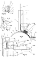
- the nozzle 10 is shown in FIG. 1 together with a cooling drum 22.
- the yarn entering from above is guided through an inlet part 12 to the point at which hot air or superheated steam is introduced through channels which point obliquely downwards - it can be one or more channels.
- This air flows through the adjoining conveying part 14 together with the yarn 1 until it enters the upsetting part 16.
- the upsetting part is preferably formed by longitudinally oriented lamellae or slots arranged around the yarn, through which the hot air can flow radially outwards.
- the so-called plug 1 ′ is formed in the upset part and maintains its shape and density along a subsequent first guide part 18 and second guide part 20. In contrast to the prior art, the yarn plug is continued in such a way that it cannot expand.
- the yarn is deflected essentially transversely to its original direction, which points downward in the figure.
- the second guide part 20 continues over a certain length along the circumference of a rotating, perforated drum 22, on the surface of which the textured yarn is guided in a channel 24.
- the term "second guide part” is to be understood on the one hand as a cover over the drum, on the other hand the groove section in the drum under the cover, further also the combination cover / groove section, with which the plug 1 'is guided on all sides.
- a supply point for cooling air indicated by the arrow 52e in FIG. 1.
- a connecting line at 52e for the medium mentioned for conditioning the thread is connected to the guide part or to the shoe 20.
- the plug is thus conditioned or cooled on the one hand by blowing out a medium on the surface of the cooling drum, and on the other hand by the subsequent pressurization of the drum, as will be described below.
- the Yarn stoppers form loops due to a lack of lateral guidance, which leads to partial expansion of the graft occurs. Because of this free appearance of the yarn plug on As mentioned at the beginning, the nozzle exit is a stronger one according to the prior art Braking in the area of the plug formation due to friction, that is to say in the compression part 16, necessary to achieve the desired curling effect. This can change when the Operating conditions that have an influence on the coefficient of friction lead to problems.
- a nozzle block 100 in which a plurality of texturing nozzles can be combined, is arranged on a first drum 22, corresponding to the side view in FIG. 1.
- a nozzle 10 and a second guide part 20 are close to a groove 220, respectively at channel 24.
- the drum wall is perforated in the area of the groove 220, indicated in FIG. 1 a by the gray area within the area of the groove 220.
- the thread runs of the filament yarn 20 from the nozzle block 100 to the first drum 22 and further to a second drum 23 are indicated by thin, dotted lines.
- the drum 23, like also the drum 22, is provided with a perforation in the area of the thread path of a thread 1, as indicated by the gray areas within the outline of the drums.
- a perforation or bores air enters the interior of the drums, since the interior of the drums is pressurized by connecting a fan 30 via a duct 32.
- Different pressure levels can prevail in the respective interior of the drums 22 and 23. While the air flowing through the bores 222 according to FIG. 1 b into the interior of the drum 22 across the plug 1 ′ according to the direction of the arrow into the groove 220, which enters the interior through bores according to FIG.
- the air entering the second drum 23 primarily has the task of cooling the thread, so that it cools down on the drum 23 side to the ambient temperature and is drawn off by conveyor rollers and on can be wound on a spool.
- the bores 222 in the wall of the first drum 22 are preferably effected by machining or by eroding, while the second drum 23 can have a jacket made of perforated sheet metal, since it does not have to be manufactured in close manufacturing tolerances.
- the first drum 22 is preferably machined, at least on the outer circumference, so that it can be arranged at a very short distance from the nozzle block 100.
- the plug is formed in the texturing nozzle 10 but its discharge speed and packing density are not controlled in the nozzle because it is not adequately braked within the nozzle channel, due to the weak friction of the plug within the compression part 16, or guide part 18.
- This is because the cross section of the channel in the upsetting part 16, or in the first guide part 18, in the material flow direction increases comparatively strongly, corresponding to a cone angle of 1 to 10 degrees, if the inner wall of the upsetting part 16 or the guide part 18, is conical.
- an accurate and close position of a texturing nozzle 10 is relative to that Thread track on the first drum 22 necessary because of the removal speed and packing density of a plug not in the texturing nozzle itself, but only on The circumference of the first drum is determined.
- the first drum 22 from the nozzle block 100, or from the Texturing nozzles 10 are moved away by pivoting or pushing away the drum 22 is advantageously accomplished by the nozzle block 100.
- the nozzle block 100, or a single texturing nozzle 10, of the first drum 22 can be moved away by means of a displacement device. According to Fig.
- the drum 1 a can a drum 22 via a shaft, indicated by dash-dotted lines, with a drive 224 connected to storage, which is fixedly mounted in a support member 226.
- the drive 224 preferably consists of a controlled by a frequency converter or regulated (asynchronous) motor in a unit with a reduction gear, the drum shaft 22 w being guided through at least two bearings in the drive 224 becomes.
- the support part 226 can be designed as a housing, which is either in a Pivot bearing 226 'is housed in a frame or it can be in a guide bearing 229 sit.
- the drum 22 is to be moved away to provide a swivel device 228 a from the nozzle block 100, while in the other Case, when the support member 226 is displaceable in the guide bearing 229, a displacement device 228 b is necessary.
- the latter devices are preferably pneumatic or hydraulic drive cylinders.
- the second drum 23 also has a drive 234 with storage, which is also an independent, speed-controlled May have an electric motor.
- a support area e for the thread 1 or Plug 1 'and on the drum 23 a support area f.
- the deflection of the thread or grafting in the range e is preferably 180 ... 270 degrees, and in the range f between 90 and 270 degrees.
- the running directions of the thread or graft are with indicated by a sequence of arrows.
- the drums point at the running point of each thread a depression, preferably a groove 220.
- a second and, or or, third blowing device 20a, 20b for cooling air can be arranged with blow-out openings directed towards the thread run.
- the second and possibly also the third or second or third blowing device is performed as set forth in connection with the description of Figure 4.
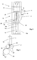
- the nozzle 10 is also in a conveying part 14, an upsetting part 16 and articulated a guide part 18, the latter also being called a plug guide tube.
- the Conveying part 14 enters air laterally into a conveying channel according to the arrows drawn in above through which the yarn to be textured is guided downwards.
- the Compression part is divided into a lamella holder 26 according to the exemplary embodiment which sit below slats 28, which are arranged in a plurality in a circle are so that slots or gaps are formed between the lamellae, through which in the region of the upsetting part 16 the air in the direction of the arrow at 28 more or less radially exits through the slots between the lamellae.
- the slat holder 26 can be designed as a flange, either in one piece with the slats 28 is executed, or the slat holder carries the slats 28, which in the Lamellar holder used, and connected to it for example by soldering become.
- the outer contour 28 'of the lamellae can be indicated by solid lines run at an angle to the flow direction of the air or the transport direction of the yarn, or, as indicated by dashed lines, the lamellae are essentially outside designed parallel to the direction of flow and run at least on the outlet side End of the plug at an angle to the conveying direction, so that the External lamella edges essentially form a circular truncated cone, which circular truncated cone into an end piece 18 ′ or into the guide part or the plug guide tube 18 protrude, the end piece 18 'or the guide part 18 also having a frustoconical shape Have area.
- the fins 28 are preferably on the outlet side and the end piece 18 'or the guide part 18 on the inlet side so that between the Outer contour 28 'of the slats 28 and the inner surface of the end piece 18' or Guide part 18 is formed a narrow gap of approximately constant height. That gap also has the shape of a circular truncated cone.
- the angle a between a first auxiliary line a 'on the outlet-side outer contour 28' of a lamella 28 with a second auxiliary line b 'in the extension of a generatrix of the truncated circular cone on the inlet side of the guide part 18 can form a first angle a, while the second auxiliary line b' also an edge 10a of the nozzle 10 forms an angle b.
- a separating plane 18 ′′ can lie between the end piece 18 ′ and the first guide part 18.
- FIG. 3 again shows schematically that a nozzle 10 is subsequently connected either a pair of delivery rollers 22 'is provided for pulling off the yarn plug formed can be, or a single drum 22, over the surface of which the plug is discharged in a controlled manner, as described in German patent application DE 199 55 227.4 is. The latter application is an integral part of the present View registration.
- FIG. 4a shows the parts in FIG Figure 4 is a plan view of the side of the shoe 20 or the drum facing the drum Air baffle on the blowing device 20a.
- the air baffle is just like for that Blower device 20b with a strongly drawn, curved line in the Side view of the arrangement shown.
- the breakthroughs can be according to Figure 4a are circular or other shaped openings.
- FIG 4 is an air supply point for cooling air is shown on the drum 23, with a Connection spigot next to the arrow at 52e and a hood, on the one hand with the spigot and on the other hand connected to an air baffle, which over the surface of a Cooling drum, here designated 23, is tensioned.
- the blowing device is also corresponding 20a executable.
- the medium, or in particular the cooling air is therefore at one Version with two cooling drums 22 and 23 over the shoe 20, further over one Blowing device 20a and 20b supplied, preferably carried out by means of a connecting piece and a hood with air baffle, designated 20c in Figure 4.
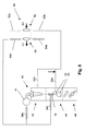
- FIG. 5 shows an overview of a production plant 40 for textured filament yarn shown schematically, taking into account the air flows for cooled air or for heated air.
- Plastic material is heated by an extruder 41, the spinning device 42 fed with a spinning beam and a cooling shaft.
- the texturing system 44 comprises further at least one or, as indicated in FIG. 5, two cooling drums 22, 23 with a feed point 52e analogous to the feed point 52d on the spinning device 42 for cooled Air.
- a stretching device is again located below the texturing system 44 and take-up means 46 for the textured material.
- a refrigeration system 50 In the refrigeration system 50 is a supply point 52a for ambient air, further one Tapping point 52b for cooled air, each indicated by dotted arrows.
- the Refrigeration system includes, for example, an evaporator 52 with a heat exchanger for a cooling medium, being in the heat exchanger by the evaporation of the cooling medium energy is withdrawn from the ambient air flowing in at 52a, this being based on the required mass is cooled and further to the removal point 52b Production facility 40 is performed.
- the evaporator 52 becomes one of the incoming ones Energy taken from ambient air per unit time E2 or power supplied, indicated by arrow E2.
- Cooled air is particularly at the supply point 52e to the cooling drums 22, 23 introduced, as in detail in connection with the description of the figures of Figure 4 is executed.
- the air ducts are shown in simplified form; it goes without saying that in order to maintain the desired temperature in each case relevant measures are necessary, for example an electrical one Heating in the extruder 41 or an admixture of additional air, indicated by the solid arrow at 52e.
- the supply points 52d and 52e for cooling air on the chute of the spinning device 42 and on the texturing system 44 are with dotted arrows indicated, correspondingly the supply points for hot air at the supply points 54c and 54f with arrows drawn out.
- the energy E2 im fed into the evaporator in the corresponding heat exchanger Refrigeration cycle per unit of time or the corresponding output is smaller than that in Heat exchanger at compressor 54 converted, i.e. to the inflowing air Energy per unit of time or power E1.
- the difference corresponds to that in the compressor 54 performance to be applied to the refrigerant in the refrigeration system 50.
Landscapes
- Engineering & Computer Science (AREA)
- Textile Engineering (AREA)
- Mechanical Engineering (AREA)
- Physics & Mathematics (AREA)
- Fluid Mechanics (AREA)
- Yarns And Mechanical Finishing Of Yarns Or Ropes (AREA)
- Treatment Of Fiber Materials (AREA)
- Spinning Methods And Devices For Manufacturing Artificial Fibers (AREA)
Abstract
Description
- Luft
- Wassernebel
- Wasser
- CO2
- N2
- Spin Finish (Wasser-Oel-Emulsion)
Es zeigen:
- Fig. 1
- schematisch einen Schnitt durch eine Texturierdüse mit einer anschliessenden Kühltrommel
- Fig. 1 a
- eine Ansicht einer Texturieranlage in schematischer Darstellung
- Fig. 1 b
- einen Meridianschnitt durch einen Teil einer Trommelwand mit einem quergeschnittenen Pfropfen
- Fig. 1 c
- eine Übersicht über die relative Lage eines Düsenblocks, der ersten und der zweiten Trommel zueinander
- Fig. 2
- einen Schnitt durch eine Texturierdüse gemäss der Erfindung in einer schematischen Darstellung
- Fig. 3
- eine Übersichtszeichnung einer Texturierdüse mit an sie anschliessenden Walzen bzw. Trommeln
- Fig. 4 und Fig. 4a
- Kühleinrichtungen, beziehungsweise Kühlluftzufuhreinrichtungen
- Fig. 5
- schematisch ein Luftführungssystem für die gesamte Fadenproduktionsanlage.
Im Bereich des Führungsteils 20 bzw. Schuhs 20 befindet sich eine Zuführstelle für Kühlluft, durch den Pfeil 52e in Figur 1 angedeutet. Eine Anschlussleitung bei 52e für das erwähnte Medium zur Konditionierung des Fadens ist an den Führungsteil bzw. an den Schuh 20 angeschlossen. Innerhalb des Schuhs befindet sich ein Bohrungssystem, welches gegen die Oberfläche des Pfropfens 1' offen ist. Im Inneren des Schuhs ist eine Verbindung zwischen der Zuleitung bei 52e und dem Bohrungssystem 52f. Der Pfropfen wird also einerseits durch das Ausblasen eines Mediums an der Oberfläche der Kühltrommel konditioniert bzw. gekühlt, andererseits durch die nachfolgende Unterdruckbeaufschlagung der Trommel, wie nachfolgend beschrieben wird.
| - Aussendurchmesser der ersten Trommel 22 | 100 ... | 200 mm |
| - Tiefe der Nut 220 | 4 ... | 8 mm |
| - Breite der Nut 220 | 6 ... | 10 mm |
| - Durchmesser der Bohrungen 222 | 0,5 ... | 1 mm |
| - Anzahl der Bohrungen 222 am Grund der Nut | 2'000 ... | 10'000 |
| - Anzahl Fadenspuren, bzw. Nuten 220 je Trommel 22 | 2 bis | 6 (8) |
| - Abstand d zwischen Düse 10 oder zweites Führungsteil 20 vom äusseren Umfang der Trommel 22 | 0,5... | 2 mm |
| - Aussendurchmesser der zweiten Trommel 23 | 300 ... | 1000 mm |
| - Temperatur der in die Düse 10 einströmenden Luft, bzw. des Dampfes | 160... | 200 ° C |
| - Temperatur des Pfropfens 1' beim Ablaufen von der Trommel 22, bzw. beim Auflaufen auf die Trommel 23 | 60 ... | 100 ° C |
| - Umschlingungswinkel des Pfropfens 1' auf der ersten Trommel 22 vom Auflaufpunkt bei der Düse 1 bis zum Ablaufpunkt bei einem Leitelement 22 a | 120 ... | 270° |
| - Verhältnis der Geschwindigkeit des in die Düse 10 eintretenden Fadens zur Umfangsgeschwindigkeit der Trommel 22 | 50... | 120 |
Claims (43)
- Verfahren zur Bildung eines texturierten Fadens in einer Texturieranlage mit einer Texturierdüse und einer daran angeschlossenen ersten Trommel (22) und einer weiteren Trommel (23), dadurch gekennzeichnet, dass der Faden auslaufseitig einer Texturierdüse (10) am Umfang einer Trommel (22) in Form eines Pfropfens (1') reibschlüssig (und bevorzugt wenigstens zum Teil formschlüssig) geführt wird, so dass die Geschwindigkeit in Längsrichtung des Pfropfens (1) am Umfang der Trommel (22) mit der Umfangsgeschwindigkeit der Trommel im Bereich der Führung (220) übereinstimmt, wobei lufttechnische Mittel (222) vorgesehen sind, um die Haftung des Pfropfens (1) am Umfang der Trommel (22) zu verbessern, wobei durch eine Druckdifferenz in einem Luftleitsystem (30) eine Anpressung des Pfropfens (1) an der Oberfläche der Trommel (22) bewirkt wird, und dass der Pfropfen bezüglich einer Soll-Transportgeschwindigkeit und Soll-Packungsdichte durch die form- und reibungsschlüssige Führung unter Luftbeaufschlagung bis zu einer Ablaufstelle bei einem Leitelement (22 a) auf der ersten Trommel geführt und auf eine zweite Trommel (23) übergeleitet wird, auf welcher der Pfropfen gegebenenfalls ausgedehnt und an weitere Führungs-, beziehungsweise Transportrollen (22'), weitergegeben wird.
- Verfahren nach Anspruch 1, dadurch gekennzeichnet, dass der Faden in der Texturierdüse mit Luft oder Dampf erhitzt und gestaucht wird, in gestauchtem Zustand am Umfang einer ersten Trommel (22) in die Düse (10) abgebremst und abgekühlt und anschliessend auf einer weiteren Trommel (23) auf Umgebungstemperatur abgekühlt wird.
- Verfahren nach Anspruch 1, dadurch gekennzeichnet, dass der Faden in der Texturierdüse mit Luft oder Dampf auf 160 bis 200° C erhitzt und gestaucht wird, in gestauchtem Zustand am Umfang einer ersten Trommel (22) auf 1/50 bis 1/80 seiner Eintrittsgeschwindigkeit in die Düse (10) abgebremst und auf eine Temperatur von 60 bis 100° C abgekühlt und anschliessend auf einer weiteren Trommel (23) auf Umgebungstemperatur abgekühlt wird.
- Verfahren nach einem der vorstehenden Ansprüche, dadurch gekennzeichnet, dass der Faden (1), beziehungsweise Pfropfen (1'), zwischen der Texturierdüse (10) und der ersten Trommel (22) so eng geführt wird, dass zwischen der Austrittsseite der Texturierdüse (10), beziehungsweise einem daran anschliessenden Führungsteil (20) und dem Umfang der Trommel (22), ein Abstand von 0.5 bis 2.00 mm eingehalten wird.
- Verfahren nach einem der vorstehenden Ansprüche, dadurch gekennzeichnet, dass der Faden (1), beziehungsweise Pfropfen (1'), am Umfang der ersten Trommel (22) durch einen in das Innere der Trommel eintretenden Luftstrom festgehalten wird, wobei dieser Luftstrom durch eine Druckdifferenz zwischen dem Aussenumfang der Trommel (22) und dem Innern der Trommel bevorzugt in Höhe von 100 ... 250 mm Wassersäule sowie einer Perforation (222) im Trommelmantel erzeugt wird.
- Verfahren nach einem der vorstehenden Ansprüche, dadurch gekennzeichnet, dass der Faden (1), beziehungsweise Pfropfen (1'), am Umfang der zweiten Trommel (23) ebenfalls durch einen Luftstrom abgekühlt wird, der bevorzugt im Bereich des Fadenlaufs durch eine Perforation in das Innere der Trommel (23) eintritt.
- Verfahren nach einem der vorstehenden Ansprüche, dadurch gekennzeichnet, dass die Grössenrelation zwischen der Dicke des Pfropfens (1) und einer Nut (220) in der Trommel (22) so gewählt wird, dass der Pfropfen an den Umfang der Trommel (22) angelegt diese Nut annähernd ausfüllt, beziehungsweise vollständig ausfüllt, beziehungsweise zu 70 bis 100 % innerhalb der Nut (220) liegt und zu 0 bis 30 % seiner Querschnittsfläche ausserhalb der Trommel zu liegen kommt.
- Verfahren nach einem der vorstehenden Ansprüche, dadurch gekennzeichnet, dass die erste Trommel (22) vor Beginn des Texturierprozesses vom Düsenblock (100), beziehungsweise einer einzelnen Texturierdüse (10), weggeschwenkt oder weggeschoben wird, und dass nach Einziehen eines oder mehrerer Fäden (1) die Trommel (22) bis auf minimal 0.5 mm an die Texturierdüse (10) oder den Düsenblock (100) heranbewegt wird, oder dass umgekehrt die Texturierdüse (10), beziehungsweise der Düsenblock (100), von der Trommel (22) entsprechend wegbewegt wird und anschliessend wieder herangefahren wird.
- Verfahren nach einem der vorstehenden Ansprüche, dadurch gekennzeichnet, dass der Faden ablaufseitig der zweiten Trommel (23) durch ein Mono- oder Duo-Lieferwerk abgezogen wird.
- Texturieranlage, beziehungsweise Texturierdüse und Pfropfentransporteinrichtung, zur Durchführung des Verfahrens nach einem der vorstehenden Ansprüche, dadurch gekennzeichnet, dass eine erste Trommel (22) unmittelbar an einer Texturierdüse (10), beziehungsweise einem Düsenblock (100), angeordnet ist, wobei Führungsmittel (20, 220) entlang des Umfangs der ersten Trommel (22) vorgesehen sind, um einen Fadenpfropfen kontrolliert unter konstanten Verhältnissen am Umfang der Trommel abzuführen, und dass am Umfang der Trommel (22) ein Leitelement (22 a, 22 b) ausserhalb des Umfangs der Trommel (22) angeordnet ist, zur Abführung des Pfropfens (1) auf eine zweite Trommel (23), welche mit Mitteln zum Abkühlen des Fadenpfropfens ausgestattet ist.
- Anlage nach Anspruch 10, dadurch gekennzeichnet, dass eine erste Trommel (22) mit einem Abstand von 0,5 bis 2,0 mm an eine Texturierdüse (10), beziehungsweise an einen Düsenblock (100), angeordnet ist, mit einem Aussendurchmesser von maximal 100 bis 200 mm, wobei Führungsmittel (20, 220) entlang des Umfangs der ersten Trommel (22) vorgesehen sind, um einen Fadenpfropfen kontrolliert unter konstanten Verhältnissen am Umfang der Trommel abzuführen, und dass in einem Winkelbereich zwischen 120 und 270 ° am Umfang der Trommel (22) ein Leitelement (22 a, 22 b) von der Texturierdüse (10) aus gemessen ausserhalb des Umfangs der Trommel (22) angeordnet ist, zur Abführung des Pfropfens (1) auf eine zweite Trommel (23), welche mit Mitteln zum Abkühlen des Fadenpfropfens auf Umgebungstemperatur ausgestattet ist.
- Anlage nach einem der Ansprüche ab Anspruch 10, dadurch gekennzeichnet, dass der Führungsteil (20) am Umfang der Trommel (22) durch eine Nut (220) in der Trommel gebildet wird.
- Anlage nach einem der Ansprüche ab Anspruch 10, dadurch gekennzeichnet, dass von der Nut (220) Durchbrüche, beziehungsweise Bohrungen (222), in das Innere der Trommel (22) führen, und dass eine Unterdruckquelle (30) über einen Kanal (32) an das Innere der Trommel (22) angeschlossen ist.
- Anlage nach einem der Ansprüche ab Anspruch 10, dadurch gekennzeichnet, dass die Trommel (22) mit einem Tragteil (226) von einer Texturierdüse (10), beziehungsweise dem Düsenblock (100), wegbewegbar ist.
- Anlage nach einem der Ansprüche ab Anspruch 10, dadurch gekennzeichnet, dass die Trommel (22) schwenkbar (226') oder verschiebbar (229) angeordnet ist.
- Anlage nach einem der Ansprüche ab Anspruch 10, dadurch gekennzeichnet, dass die Trommel (22) mittelbar oder unmittelbar mit einer Schwenkeinrichtung (228 a) und/oder einer Verschiebe-Einrichtung (228 b) verbunden ist.
- Anlage nach einem der Ansprüche ab Anspruch 10, dadurch gekennzeichnet, dass wenigstens eine der Trommeln auf einer Trommelwelle sitzt, welche mit einem Direktantrieb (224) mit Lagerung verbunden ist.
- Anlage nach einem der Ansprüche ab Anspruch 10, dadurch gekennzeichnet, dass von einer Faden-, beziehungsweise Pfropfenführungsnut (220), in der ersten Trommel (22) Bohrungen in das Innere der Trommel führen, bevorzugt in mehreren Lochreihen nebeneinander, mit einem Durchmesser zwischen 0.5 und 1.0 mm.
- Anlage nach einem der Ansprüche ab Anspruch 10, dadurch gekennzeichnet, dass in der ersten Trommel (22) mindestens eine Nut (220) eingelassen ist, mit einem wenigstens annähernd trogförmigen Querschnitt einer Breite zwischen 6.0 und 10 mm und einer Tiefe zwischen 4.0 und 8.0 mm.
- Anlage nach einem der Ansprüche ab Anspruch 10, dadurch gekennzeichnet, dass der Durchmesser der ersten Trommel (22) zwischen 100 und 200 mm beträgt, und dass eine zweite Trommel (23) einen Durchmesser zwischen 300 und 1'000 mm aufweist.
- Düse für eine Anlage nach einem der vorstehenden Ansprüche, auf eine Anlage bezogen, insbesondere Texturierdüse (10) mit einem Stauchteil (16), dadurch gekennzeichnet, dass die austrittsseitig des Stauchteils (16) liegenden Lamellenenden frei zur Umgebung, insbesondere berührungslos zu umgebenden Teilen der Düse, und/oder zu einem anschliessenden Führungsteil (18), ausgeführt sind.
- Düse nach Anspruch 21, gekennzeichnet durch einen in Förderrichtung vor dem Stauchteil liegenden Förderteil (14) und einen nach dem Stauchteil (16) angeordneten Führungsteil oder ein Pfropfenleitrohr (18).
- Düse nach einem der Ansprüche ab Anspruch 21, dadurch gekennzeichnet, dass die Düse als Texturierdüse ausgeführt ist.
- Verfahren zur Bildung eines texturierten Fadens in einer Texturieranlage mit einer Texturierdüse und einer daran angeschlossenen Trommel (22), wobei der Faden auslaufseitig einer Texturierdüse (10) am Umfang einer Trommel (22) in Form eines Pfropfens (1') geführt wird, und bevorzugt lufttechnische Mittel (222) vorgesehen sind, dadurch gekennzeichnet, dass am Umfang der Trommel (22) der Pfropfen (1) durch Einwirkung von aussen, insbesondere mittels einer Blaseinrichtung (20a), bevorzugt durch eine auf den Fadenlauf gerichtete Ausblasöffnung (52f), abgekühlt wird, und dass durch den Umfang der Trommel nach innen eine Saugwirkung erzeugt wird.
- Verfahren nach Anspruch 24 mit einer ersten an die Texturierdüse angeschlossenen Trommel (22), insbesondere auch einer weiteren Trommel (23), wobei der Faden auslaufseitig einer Texturierdüse (10) am Umfang einer Trommel (22) in Form eines Pfropfens (1') reibschlüssig und wenigstens zum Teil formschlüssig geführt wird, so dass die Geschwindigkeit in Längsrichtung des Pfropfens (1) am Umfang der Trommel (22) mit der Umfangsgeschwindigkeit der Trommel im Bereich der Führung (220) übereinstimmt, wobei bevorzugt lufttechnische Mittel (222) vorgesehen sind, um die Haftung des Pfropfens (1) am Umfang der Trommel (22) zu verbessern, wobei durch eine Druckdifferenz in einem Luftleitsystem (30) eine Anpressung des Pfropfens (1) an der Oberfläche der Trommel (22) bewirkt wird, und der Pfropfen bezüglich seiner Transportgeschwindigkeit und Packungsdichte durch die form- und reibungsschlüssige Führung unter Luftbeaufschlagung bis zu einer Ablaufstelle bei einem Leitelement (22 a) geführt und abgeleitet wird, während der Pfropfen abgekühlt, gegebenenfalls ausgedehnt und an weitere Führungs-, beziehungsweise Transportrollen (22'), weitergegeben wird.
- Verfahren nach Anspruch 24 oder 25, dadurch gekennzeichnet, dass der Pfropfen bei einem ersten Führungsteil (20) an der Auflaufstelle des Pfropfens (1') auf der Trommel (22) mittels einer Blaseinrichtung (20a) gekühlt wird.
- Verfahren nach einem der Ansprüche ab Anspruch 24, dadurch gekennzeichnet, dass der Pfropfen nach dem ersten Führungsteil (20) nach der Auflaufstelle des Pfropfens (1') auf der Trommel (22) mittels einer Blaseinrichtung (20a) gekühlt wird.
- Verfahren nach einem der Ansprüche ab Anspruch 24, dadurch gekennzeichnet, dass der Pfropfen (1') auf einer weiteren Kühltrommel (23) mittels einer weiteren Blaseinrichtung (20b) gekühlt wird.
- Verfahren nach einem der Ansprüche ab Anspruch 24, dadurch gekennzeichnet, dass der Faden in der Texturierdüse mit Luft oder Dampf erhitzt und dann gestaucht wird, in gestauchtem Zustand am Umfang einer ersten Trommel (22) abgebremst und abgekühlt und anschliessend auf einer weiteren Trommel (23) auf Umgebungstemperatur abgekühlt wird.
- Verfahren nach einem der Ansprüche ab Anspruch 24, dadurch gekennzeichnet, dass der Faden in der Texturierdüse mit Luft oder Dampf auf 160 bis 200 ° erhitzt und dann gestaucht wird, in gestauchtem Zustand am Umfang einer ersten Trommel (22) auf 1/50 bis 1/80 seiner Eintrittsgeschwindigkeit in die Düse (10) abgebremst und auf eine Temperatur von 60 bis 100 ° Celsius abgekühlt und anschliessend auf einer weiteren Trommel (23) auf Umgebungstemperatur abgekühlt wird.
- Verfahren nach einem der Ansprüche ab Anspruch 24, dadurch gekennzeichnet, dass der Faden (1), beziehungsweise Pfropfen (1'), zwischen der Texturierdüse (10) und der ersten Trommel (22) so eng geführt wird, dass zwischen der Austrittsseite der Texturierdüse (10), beziehungsweise einem daran anschliessenden Führungsteil (20) und dem Umfang der Trommel (22), ein Abstand von 0.5 bis 2.00 mm eingehalten wird.
- Verfahren nach einem der Ansprüche ab Anspruch 24, dadurch gekennzeichnet, dass der Faden (1), beziehungsweise Pfropfen (1'), am Umfang der ersten Trommel (22) durch einen in das Innere der Trommel eintretenden Luftstrom festgehalten wird, wobei dieser Luftstrom durch eine Druckdifferenz zwischen dem Aussenumfang der Trommel (22) und dem Innern der Trommel in Höhe von 100 ... 250 mm Wassersäule sowie einer Perforation (222) im Trommelmantel erzeugt wird.
- Verfahren nach einem der Ansprüche ab Anspruch 24, dadurch gekennzeichnet, dass der Faden (1), beziehungsweise Pfropfen (1'), am Umfang der zweiten Trommel (23) ebenfalls durch einen Luftstrom abgekühlt wird, der bevorzugt im Bereich des Fadenlaufs durch eine Perforation in das Innere der Trommel (23) eintritt.
- Verfahren nach einem der Ansprüche ab Anspruch 24, dadurch gekennzeichnet, dass die Grössenrelation zwischen der Dicke des Pfropfens (1) und einer Nut (220) in der Trommel (22) so gewählt wird, dass der Pfropfen an den Umfang der Trommel (22) angelegt diese Nut annähernd ausfüllt, beziehungsweise vollständig ausfüllt, beziehungsweise zu 70 bis 100 % innerhalb der Nut (220) liegt und zu 0 bis 30 % seiner Querschnittsfläche ausserhalb der Trommel zu liegen kommt.
- Texturieranlage mit einer Texturierdüse und einer daran angeschlossenen Trommel (22), wobei auslaufseitig einer Texturierdüse (10) am Umfang einer Trommel (22 eine Führung für einen Pfropfens (1') vorgesehen ist, und lufttechnische Mittel (222) vorgesehen sind, insbesondere zur Durchführung eines der Verfahren laut einem der vorstehenden Verfahrensansprüche, dadurch gekennzeichnet, dass an mindestens einer Trommel (22) eine Zuführstelle (52e, 20) vorgesehen ist, zum Ausgeben eines Konditionierungsmediums an den Pfropfen (1'), und dass das Innere der luftdurchlässigen Trommel unter Wirkung eines Unterdrucks einer Saugeinrichtung steht.
- Anlage nach Anspruch 35, dadurch gekennzeichnet, dass an mindestens einer Trommel (22) zur Führung eines Fadenpfropfens unmittelbar nach dem Texturieren ein erster Führungsteil (20) mit einer Zuführstelle für Kühlluft (52e) und einem Bohrungssystem (52f) in dem Führungsteil (20) vorgesehen ist, zum Ausgeben eines Konditionierungsmediums an den Pfropfen (1').
- Anlage nach Anspruch 35 oder 36, gekennzeichnet durch eine Blaseinrichtung (20a), gebildet durch einen Stutzen an einer Zuführungsstelle (52e), weiter durch eine Haube (20c) mit einem Luftleitblech, das sich über einen Teil des Umfangs einer Kühltrommel (22, 23) erstreckt.
- Anlage nach einem der vorstehenden Ansprüche ab Anspruch 35, bezogen auf eine Texturieranlage, gekennzeichnet durch eine dritte Blaseinrichtung (20b), zusätzlich zu einer ersten und zweiten Blaseinrichtung (20a), jeweils an einer Kühltrommel (22 bzw. 23) angeordnet, oder alternativ zu einem Führungsteil (20) oder Schuh an der Auflaufstelle des Fadenpfropfens im Anschluss an eine Texturierdüse (10).
- Anlage nach einem der vorstehenden Ansprüche ab Anspruch 35, bezogen auf eine Texturieranlage, gekennzeichnet durch ein Bohrungssystem (52f) im ersten Führungsteil (20) bzw. in einer ersten Blaseinrichtung (20a) bzw. in einer zweiten Blaseinrichtung (20b).
- Anlage nach einem der vorstehenden Ansprüche ab Anspruch 35, bezogen auf eine Texturieranlage, gekennzeichnet durch eine Kälteanlage (50) mit einer Zuführstelle (52a) bzw. Entnahmestelle (52b) für abzukühlende Luft und eine Zuführstelle (54a) bzw. Entnahmestelle (54b) für zu erwärmende Luft, jeweils in Wärmetauscher einerseits bei einem Verdampfer (52) bzw. Verdichter (54) für ein Kältemedium der Kälteanlage (50), weiter mit Verbindungsleitungen für Luftströme zumindest an eine Zuführstelle (52) für Kühlluft an mindestens eine Kühltrommel (22) für mindestens einen Fadenpfropfen (1'), weiter zu mindestens einer Zuführungsstelle (54f) für erwärmte Luft an mindestens eine Texturierdüse (10') einer Texturieranlage (44).
- Texturieranlage nach dem vorstehenden Anspruch, gekennzeichnet durch eine Zuführstelle (54c) für erhitzte Luft zur Beheizung eines Extruders (41) an einer der Texturieranlage (44) vorgelagerten Spinneinrichtung (42).
- Anlage nach einem der vorstehenden Ansprüche ab Anspruch 35, dadurch gekennzeichnet, dass eine erste Trommel (22) an einer Texturierdüse (10), beziehungsweise einem Düsenblock (100), angeordnet ist, wobei Führungsmittel (20, 220) entlang des Umfangs der ersten Trommel (22) vorgesehen sind, um einen Fadenpfropfen kontrolliert unter konstanten Verhältnissen auf den Umfang der Trommel abzuführen, und ein Leitelement (22 a, 22 b) ausserhalb des Umfangs der Trommel (22) angeordnet ist, zur Abführung des Pfropfens (1') auf eine zweite Trommel (23), welche mit Mitteln zum Abkühlen des Fadenpfropfens auf Umgebungstemperatur ausgestattet ist.
- Anlage nach einem der vorstehenden Ansprüche ab Anspruch 35, dadurch gekennzeichnet, dass der Führungsteil (20) am Umfang der Trommel (22) durch eine Nut (220) oder Rinne in der Trommel gebildet wird, oder durch eine Abdeckung(20), oder durch eine Kombination aus einer Nut (220) in der Trommel mit einer Abdeckung(20) gebildet wird.
Applications Claiming Priority (2)
| Application Number | Priority Date | Filing Date | Title |
|---|---|---|---|
| DE10202788A DE10202788A1 (de) | 2002-01-25 | 2002-01-25 | Texturieranlage und Texturierdüse hierfür |
| DE10202788 | 2002-01-25 |
Publications (2)
| Publication Number | Publication Date |
|---|---|
| EP1331291A2 true EP1331291A2 (de) | 2003-07-30 |
| EP1331291A3 EP1331291A3 (de) | 2003-11-26 |
Family
ID=7713018
Family Applications (1)
| Application Number | Title | Priority Date | Filing Date |
|---|---|---|---|
| EP03001168A Withdrawn EP1331291A3 (de) | 2002-01-25 | 2003-01-21 | Texturieranlage und Texturierdüse hierfür |
Country Status (4)
| Country | Link |
|---|---|
| US (4) | US6983519B2 (de) |
| EP (1) | EP1331291A3 (de) |
| CN (1) | CN1439756A (de) |
| DE (1) | DE10202788A1 (de) |
Cited By (1)
| Publication number | Priority date | Publication date | Assignee | Title |
|---|---|---|---|---|
| WO2008043739A1 (de) * | 2006-10-14 | 2008-04-17 | Oerlikon Textile Gmbh & Co. Kg | Vorrichtung zum kräuseln synthetischer filamente |
Families Citing this family (6)
| Publication number | Priority date | Publication date | Assignee | Title |
|---|---|---|---|---|
| EP1397541B2 (de) * | 2001-05-10 | 2012-02-15 | Oerlikon Textile GmbH & Co. KG | Vorrichtung zum stauchkräuseln eines synthetischen multifilen fadens |
| US7152287B2 (en) * | 2003-11-19 | 2006-12-26 | American Linc Corporation | System, apparatus, and method of reducing production loss for textured yarn and other related methods |
| US7386925B2 (en) * | 2006-10-04 | 2008-06-17 | Dietze & Schell Maschinenfabrik | Process and apparatus for the production of artificial grass |
| CN101528996B (zh) * | 2006-11-04 | 2011-03-16 | 欧瑞康纺织有限及两合公司 | 用于多纤维长丝卷曲变形的方法和装置 |
| DE102012004747A1 (de) * | 2012-03-08 | 2013-09-12 | Oerlikon Textile Gmbh & Co. Kg | Kräuselvorrichtung |
| US10440729B2 (en) * | 2016-07-28 | 2019-10-08 | Qualcomm Incorporated | Transmission of Ultra-Reliable Low-Latency Communications (URLLC) over Time Division Duplex (TDD) using a URLLC configuration for a TDD subframe |
Family Cites Families (36)
| Publication number | Priority date | Publication date | Assignee | Title |
|---|---|---|---|---|
| US2313630A (en) * | 1939-09-12 | 1943-03-09 | Owens Corning Fiberglass Corp | Method and apparatus for producing glass fibers |
| US3469293A (en) * | 1966-06-18 | 1969-09-30 | Asahi Chemical Ind | Method of and apparatus for crimping synthetic fibres |
| FR2052161A5 (de) | 1969-07-24 | 1971-04-09 | Rhodiaceta | |
| US4019228A (en) * | 1970-03-05 | 1977-04-26 | Mitsubishi Rayon Co., Ltd. | Crimping apparatus |
| US3816887A (en) * | 1972-07-17 | 1974-06-18 | Eastman Kodak Co | Swivelly mounted tailpipe for the jet device of a yarn bulking apparatus |
| US3899811A (en) * | 1972-07-22 | 1975-08-19 | Neumuenster Masch App | Crimping of synthetic plastic filaments |
| DE2507752A1 (de) * | 1975-02-22 | 1976-08-26 | Karlsruhe Augsburg Iweka | Verfahren zum kraeuseln kuenstlicher faeden |
| US4296535A (en) * | 1975-10-02 | 1981-10-27 | Allied Chemical Coporation | Apparatus for texturizing continuous filaments |
| US4118843A (en) * | 1976-07-16 | 1978-10-10 | Barmag Barmer Maschinenfabrik Aktiengesellschaft | Processes and apparatus for thermal treatment of filaments |
| US4157604A (en) * | 1977-11-18 | 1979-06-12 | Allied Chemical Corporation | Method of high speed yarn texturing |
| DE2809204A1 (de) * | 1978-03-03 | 1979-09-13 | Barmag Barmer Maschf | Vorrichtung zum thermischen behandeln, insbesondere zum kuehlen mindestens eines kontinuierlich laufenden in staukammern gebildeten fadenstopfens |
| US4765042A (en) * | 1982-03-12 | 1988-08-23 | Allied Corporation | Apparatus for texturing continuous filamentary tow |
| US4558497A (en) * | 1982-03-12 | 1985-12-17 | Allied Corporation | Method for producing commingled continuous variable texture yarn |
| US4519116A (en) * | 1983-03-16 | 1985-05-28 | Allied Corporation | Yarn texturing by moving cavity jet with fluid removal |
| US4620345A (en) * | 1983-05-19 | 1986-11-04 | Fleissner Gmbh & Company | Apparatus for crimping and setting synthetic fiber groups |
| JPS6130059A (ja) * | 1984-07-20 | 1986-02-12 | Nec Corp | 半導体装置の製造方法 |
| JP2688428B2 (ja) * | 1987-10-05 | 1997-12-10 | マシーネンファブリク リーター アクチェンゲゼルシャフト | 熱可塑性フィラメントを連続捲縮加工する方法と装置 |
| US5054173A (en) * | 1989-05-18 | 1991-10-08 | Barmag Ag | Method and apparatus for the enhanced crimping of multifilament yarn |
| RU2041981C1 (ru) * | 1989-11-11 | 1995-08-20 | Бармаг АГ | Фильера для текстурирования синтетической нити |
| JPH0429338A (ja) * | 1990-05-24 | 1992-01-31 | Nippon Mektron Ltd | Icの搭載用回路基板及びその搭載方法 |
| EP0488939B1 (de) * | 1990-11-29 | 1995-02-22 | Maschinenfabrik Rieter Ag | Verfahren und Vorrichtung zur Pfropfenauflösung nach der Texturierung |
| DE4235549C2 (de) * | 1991-10-21 | 1999-12-09 | Rohm Co Ltd | Gerät zum Justieren einer Lichtquelleneinheit |
| EP0571323A1 (de) * | 1992-05-20 | 1993-11-24 | Maschinenfabrik Rieter Ag | Vorrichtung zum kontinuierlichen Kräuseln von thermoplastischen Fäden |
| CH689040B5 (de) * | 1992-11-19 | 1999-02-26 | Rieter Ag Maschf | Verfahren und Vorrichtung zum Texturieren von thermoplastischen Fäden. |
| US5500540A (en) * | 1994-04-15 | 1996-03-19 | Photonics Research Incorporated | Wafer scale optoelectronic package |
| US5858607A (en) * | 1996-11-21 | 1999-01-12 | Kodak Polychrome Graphics | Laser-induced material transfer digital lithographic printing plates |
| US5974777A (en) * | 1998-04-21 | 1999-11-02 | Davis; David M | Yarn texturizer cooling drum |
| US6451624B1 (en) * | 1998-06-05 | 2002-09-17 | Micron Technology, Inc. | Stackable semiconductor package having conductive layer and insulating layers and method of fabrication |
| EP1026295A3 (de) * | 1999-02-06 | 2003-11-26 | Barmag AG | Verfahren und Vorrichtung zum Stauchkräuseln eines Fadens |
| US6376051B1 (en) * | 1999-03-10 | 2002-04-23 | Matsushita Electric Industrial Co., Ltd. | Mounting structure for an electronic component and method for producing the same |
| DE19955227A1 (de) * | 1999-11-17 | 2001-05-23 | Rieter Ag Maschf | Texturierdüse |
| DE10043002A1 (de) * | 2000-09-01 | 2002-03-14 | Rieter Ag Maschf | Texturierdüse |
| ES2187255B1 (es) * | 2000-10-23 | 2004-08-16 | Juan Serracant Clermont | Maquina combinada para el rizado, el termofijado y el acondicionado en sucesion de materias textiles agrupadas en forma de banda, y un metodo de rizado correspondiente. |
| EP1397541B2 (de) * | 2001-05-10 | 2012-02-15 | Oerlikon Textile GmbH & Co. KG | Vorrichtung zum stauchkräuseln eines synthetischen multifilen fadens |
| US6762072B2 (en) * | 2002-03-06 | 2004-07-13 | Robert Bosch Gmbh | SI wafer-cap wafer bonding method using local laser energy, device produced by the method, and system used in the method |
| US6888233B2 (en) * | 2003-03-10 | 2005-05-03 | Honeywell International Inc. | Systems for buried electrical feedthroughs in a glass-silicon MEMS process |
-
2002
- 2002-01-25 DE DE10202788A patent/DE10202788A1/de not_active Withdrawn
-
2003
- 2003-01-21 EP EP03001168A patent/EP1331291A3/de not_active Withdrawn
- 2003-01-22 US US10/349,485 patent/US6983519B2/en not_active Expired - Fee Related
- 2003-01-24 CN CN03121771A patent/CN1439756A/zh active Pending
-
2005
- 2005-08-31 US US11/216,994 patent/US7131172B2/en not_active Expired - Fee Related
-
2006
- 2006-10-17 US US11/581,860 patent/US20070033780A1/en not_active Abandoned
- 2006-10-17 US US11/581,819 patent/US20070028431A1/en not_active Abandoned
Cited By (1)
| Publication number | Priority date | Publication date | Assignee | Title |
|---|---|---|---|---|
| WO2008043739A1 (de) * | 2006-10-14 | 2008-04-17 | Oerlikon Textile Gmbh & Co. Kg | Vorrichtung zum kräuseln synthetischer filamente |
Also Published As
| Publication number | Publication date |
|---|---|
| DE10202788A1 (de) | 2003-07-31 |
| EP1331291A3 (de) | 2003-11-26 |
| US20070028431A1 (en) | 2007-02-08 |
| US20060010666A1 (en) | 2006-01-19 |
| CN1439756A (zh) | 2003-09-03 |
| US7131172B2 (en) | 2006-11-07 |
| US20040016092A1 (en) | 2004-01-29 |
| US6983519B2 (en) | 2006-01-10 |
| US20070033780A1 (en) | 2007-02-15 |
Similar Documents
| Publication | Publication Date | Title |
|---|---|---|
| DE2149892A1 (de) | Verfahren und Vorrichtung zum Verteilen in einem ansteigenden Gasstrom schwebender Fasern ueber eine Siebflaeche | |
| EP0224435B1 (de) | Verfahren zur Herstellung eines Vlieses aus Endlosfäden sowie Vorrichtung zur Durchführung des Verfahrens | |
| DE102016112394A1 (de) | Vorrichtung zum Schmelzspinnen und Abkühlen einer Filamentschar | |
| EP3894622B1 (de) | Strahlsaugkasten und strahlsaugverfahren | |
| DE10115618A1 (de) | Verfahren und Vorrichtung zum Überführen einer Bahn | |
| DE4013485C2 (de) | Verfahren und Vorrichtung zur Effektivierung der Bahnendaufführung in einer Papiermaschinentrockenpartie | |
| EP2783039B1 (de) | Verfahren zur überführung einer materialbahn von einer trockenanordnung zu einer nachgeordneten funktionseinheit und trockenvorrichtung | |
| WO1997047449A1 (de) | Belüftungsdüse | |
| DE10202788A1 (de) | Texturieranlage und Texturierdüse hierfür | |
| DE19527415A1 (de) | Verfahren und Vorrichtung zum Trocknen von keramischen Formlingen | |
| EP1710329A1 (de) | Verfahren und Vorrichtung zum Schmelzspinnen und Abkühlen einer Vielzahl von Filamenten | |
| DE2615365A1 (de) | Maschine fuer die beseitigung von staub von blattmaterial | |
| EP0945695A1 (de) | Vorrichtung zum Behandeln von Materialbahnen | |
| CH663222A5 (de) | Spinnanlage fuer chemiefasern. | |
| EP1101849B1 (de) | Texturierdüse | |
| EP1593762A2 (de) | Verfahren und Vorrichtung zum Stauchkräuseln eines multifilen Fadens | |
| DE3424253A1 (de) | Spinnanlage fuer chemiefasern mit anblaskasten und spinnschacht | |
| EP1184494B1 (de) | Texturierdüse | |
| DE102014100651B4 (de) | Luftdichtungsvorrichtung für einen Sprühapparat in einer Papierherstellungsmaschine | |
| DE6608412U (de) | Vorrichtung zum kontinuierlichen foerdern von schnittabak zu einer strangzigarettenmaschine. | |
| DE2237291C3 (de) | Zigarettenmaschine | |
| WO2016030136A1 (de) | Garnbildungselement für eine spinndüse einer luftspinnmaschine, luftspinnmaschine sowie verfahren zum betrieb einer solchen | |
| EP1941090A1 (de) | Vorrichtung und verfahren zur ablage von synthetischen fasern zu einem vlies | |
| EP1303656A1 (de) | Verfahren und vorrichtung zur kontinuierlichen behandlung von synthetischen fäden in einer wärmeaustauschkammer | |
| DE102009032907B3 (de) | Vorrichtung zum Entfernen von Rückständen von der Oberfläche eines bewegten Bandes sowie Bandbearbeitungsanlage |
Legal Events
| Date | Code | Title | Description |
|---|---|---|---|
| PUAI | Public reference made under article 153(3) epc to a published international application that has entered the european phase |
Free format text: ORIGINAL CODE: 0009012 |
|
| AK | Designated contracting states |
Designated state(s): AT BE BG CH CY CZ DE DK EE ES FI FR GB GR HU IE IT LI LU MC NL PT SE SI SK TR |
|
| AX | Request for extension of the european patent |
Extension state: AL LT LV MK RO |
|
| PUAL | Search report despatched |
Free format text: ORIGINAL CODE: 0009013 |
|
| AK | Designated contracting states |
Kind code of ref document: A3 Designated state(s): AT BE BG CH CY CZ DE DK EE ES FI FR GB GR HU IE IT LI LU MC NL PT SE SI SK TR |
|
| AX | Request for extension of the european patent |
Extension state: AL LT LV MK RO |
|
| RIC1 | Information provided on ipc code assigned before grant |
Ipc: 7D 02J 13/00 B Ipc: 7D 02G 1/12 A |
|
| 17P | Request for examination filed |
Effective date: 20040518 |
|
| AKX | Designation fees paid |
Designated state(s): AT BE BG CH CY CZ DE DK EE ES FI FR GB GR HU IE IT LI LU MC NL PT SE SI SK TR |
|
| STAA | Information on the status of an ep patent application or granted ep patent |
Free format text: STATUS: THE APPLICATION HAS BEEN WITHDRAWN |
|
| 18W | Application withdrawn |
Effective date: 20070220 |