EP1323956A2 - Module de commande d'un arbre rotatif de sortie et module de changement d'une condition de conduite pour automobile - Google Patents
Module de commande d'un arbre rotatif de sortie et module de changement d'une condition de conduite pour automobile Download PDFInfo
- Publication number
- EP1323956A2 EP1323956A2 EP02028723A EP02028723A EP1323956A2 EP 1323956 A2 EP1323956 A2 EP 1323956A2 EP 02028723 A EP02028723 A EP 02028723A EP 02028723 A EP02028723 A EP 02028723A EP 1323956 A2 EP1323956 A2 EP 1323956A2
- Authority
- EP
- European Patent Office
- Prior art keywords
- motor
- output
- rotating shaft
- control circuit
- gear
- Prior art date
- Legal status (The legal status is an assumption and is not a legal conclusion. Google has not performed a legal analysis and makes no representation as to the accuracy of the status listed.)
- Granted
Links
- 230000008859 change Effects 0.000 title claims description 82
- 230000007246 mechanism Effects 0.000 claims abstract description 55
- 229910052751 metal Inorganic materials 0.000 claims abstract description 7
- 239000002184 metal Substances 0.000 claims abstract description 7
- 230000005291 magnetic effect Effects 0.000 claims description 124
- 238000012545 processing Methods 0.000 claims description 55
- 238000012546 transfer Methods 0.000 claims description 24
- 229920005989 resin Polymers 0.000 claims description 18
- 239000011347 resin Substances 0.000 claims description 18
- 239000004020 conductor Substances 0.000 claims description 15
- 238000009423 ventilation Methods 0.000 claims description 13
- 230000009467 reduction Effects 0.000 claims description 5
- 229910000831 Steel Inorganic materials 0.000 claims description 4
- 239000010959 steel Substances 0.000 claims description 4
- 238000001514 detection method Methods 0.000 abstract description 21
- 239000000843 powder Substances 0.000 abstract 1
- 230000006870 function Effects 0.000 description 41
- 238000000034 method Methods 0.000 description 30
- 230000005540 biological transmission Effects 0.000 description 19
- 238000007796 conventional method Methods 0.000 description 15
- XEEYBQQBJWHFJM-UHFFFAOYSA-N Iron Chemical compound [Fe] XEEYBQQBJWHFJM-UHFFFAOYSA-N 0.000 description 12
- 239000000463 material Substances 0.000 description 10
- 230000005389 magnetism Effects 0.000 description 9
- 230000005855 radiation Effects 0.000 description 9
- 238000004364 calculation method Methods 0.000 description 8
- 230000014509 gene expression Effects 0.000 description 8
- 239000000696 magnetic material Substances 0.000 description 8
- 238000010276 construction Methods 0.000 description 7
- 238000010586 diagram Methods 0.000 description 7
- 238000009826 distribution Methods 0.000 description 6
- 239000000428 dust Substances 0.000 description 6
- 239000004593 Epoxy Substances 0.000 description 5
- 229910052782 aluminium Inorganic materials 0.000 description 5
- XAGFODPZIPBFFR-UHFFFAOYSA-N aluminium Chemical compound [Al] XAGFODPZIPBFFR-UHFFFAOYSA-N 0.000 description 5
- 230000000712 assembly Effects 0.000 description 5
- 238000000429 assembly Methods 0.000 description 5
- 239000003921 oil Substances 0.000 description 5
- 239000013464 silicone adhesive Substances 0.000 description 5
- 230000004907 flux Effects 0.000 description 4
- 229910052742 iron Inorganic materials 0.000 description 4
- 230000008569 process Effects 0.000 description 4
- 230000009257 reactivity Effects 0.000 description 3
- 238000000638 solvent extraction Methods 0.000 description 3
- 230000008901 benefit Effects 0.000 description 2
- 238000004891 communication Methods 0.000 description 2
- 230000000295 complement effect Effects 0.000 description 2
- 238000012937 correction Methods 0.000 description 2
- 230000001419 dependent effect Effects 0.000 description 2
- 230000000694 effects Effects 0.000 description 2
- 229920006332 epoxy adhesive Polymers 0.000 description 2
- 238000007726 management method Methods 0.000 description 2
- 238000003801 milling Methods 0.000 description 2
- 238000000465 moulding Methods 0.000 description 2
- 229920006395 saturated elastomer Polymers 0.000 description 2
- 239000000126 substance Substances 0.000 description 2
- XLYOFNOQVPJJNP-UHFFFAOYSA-N water Substances O XLYOFNOQVPJJNP-UHFFFAOYSA-N 0.000 description 2
- 229910000859 α-Fe Inorganic materials 0.000 description 2
- 230000009471 action Effects 0.000 description 1
- 230000002411 adverse Effects 0.000 description 1
- 229910000828 alnico Inorganic materials 0.000 description 1
- PNEYBMLMFCGWSK-UHFFFAOYSA-N aluminium oxide Inorganic materials [O-2].[O-2].[O-2].[Al+3].[Al+3] PNEYBMLMFCGWSK-UHFFFAOYSA-N 0.000 description 1
- 238000004458 analytical method Methods 0.000 description 1
- 238000006243 chemical reaction Methods 0.000 description 1
- 230000008602 contraction Effects 0.000 description 1
- 230000001276 controlling effect Effects 0.000 description 1
- 229910052593 corundum Inorganic materials 0.000 description 1
- 238000005520 cutting process Methods 0.000 description 1
- 230000004069 differentiation Effects 0.000 description 1
- 235000012489 doughnuts Nutrition 0.000 description 1
- 230000007613 environmental effect Effects 0.000 description 1
- 238000011156 evaluation Methods 0.000 description 1
- 238000002474 experimental method Methods 0.000 description 1
- 230000005294 ferromagnetic effect Effects 0.000 description 1
- 238000007667 floating Methods 0.000 description 1
- 238000012905 input function Methods 0.000 description 1
- 230000010354 integration Effects 0.000 description 1
- 238000002955 isolation Methods 0.000 description 1
- 238000005304 joining Methods 0.000 description 1
- 238000004519 manufacturing process Methods 0.000 description 1
- 229910001172 neodymium magnet Inorganic materials 0.000 description 1
- 238000010606 normalization Methods 0.000 description 1
- 230000002093 peripheral effect Effects 0.000 description 1
- 230000001105 regulatory effect Effects 0.000 description 1
- 239000012779 reinforcing material Substances 0.000 description 1
- 230000001846 repelling effect Effects 0.000 description 1
- 230000004044 response Effects 0.000 description 1
- 102200029231 rs11551768 Human genes 0.000 description 1
- 102200082816 rs34868397 Human genes 0.000 description 1
- 238000005070 sampling Methods 0.000 description 1
- 239000004065 semiconductor Substances 0.000 description 1
- 230000035945 sensitivity Effects 0.000 description 1
- 238000005476 soldering Methods 0.000 description 1
- 230000003068 static effect Effects 0.000 description 1
- 229910001845 yogo sapphire Inorganic materials 0.000 description 1
Images


Classifications
-
- G—PHYSICS
- G01—MEASURING; TESTING
- G01D—MEASURING NOT SPECIALLY ADAPTED FOR A SPECIFIC VARIABLE; ARRANGEMENTS FOR MEASURING TWO OR MORE VARIABLES NOT COVERED IN A SINGLE OTHER SUBCLASS; TARIFF METERING APPARATUS; MEASURING OR TESTING NOT OTHERWISE PROVIDED FOR
- G01D3/00—Indicating or recording apparatus with provision for the special purposes referred to in the subgroups
- G01D3/028—Indicating or recording apparatus with provision for the special purposes referred to in the subgroups mitigating undesired influences, e.g. temperature, pressure
- G01D3/036—Indicating or recording apparatus with provision for the special purposes referred to in the subgroups mitigating undesired influences, e.g. temperature, pressure on measuring arrangements themselves
- G01D3/0365—Indicating or recording apparatus with provision for the special purposes referred to in the subgroups mitigating undesired influences, e.g. temperature, pressure on measuring arrangements themselves the undesired influence being measured using a separate sensor, which produces an influence related signal
-
- F—MECHANICAL ENGINEERING; LIGHTING; HEATING; WEAPONS; BLASTING
- F16—ENGINEERING ELEMENTS AND UNITS; GENERAL MEASURES FOR PRODUCING AND MAINTAINING EFFECTIVE FUNCTIONING OF MACHINES OR INSTALLATIONS; THERMAL INSULATION IN GENERAL
- F16H—GEARING
- F16H59/00—Control inputs to control units of change-speed-, or reversing-gearings for conveying rotary motion
- F16H59/68—Inputs being a function of gearing status
- F16H59/70—Inputs being a function of gearing status dependent on the ratio established
-
- F—MECHANICAL ENGINEERING; LIGHTING; HEATING; WEAPONS; BLASTING
- F16—ENGINEERING ELEMENTS AND UNITS; GENERAL MEASURES FOR PRODUCING AND MAINTAINING EFFECTIVE FUNCTIONING OF MACHINES OR INSTALLATIONS; THERMAL INSULATION IN GENERAL
- F16H—GEARING
- F16H61/00—Control functions within control units of change-speed- or reversing-gearings for conveying rotary motion ; Control of exclusively fluid gearing, friction gearing, gearings with endless flexible members or other particular types of gearing
- F16H61/26—Generation or transmission of movements for final actuating mechanisms
- F16H61/28—Generation or transmission of movements for final actuating mechanisms with at least one movement of the final actuating mechanism being caused by a non-mechanical force, e.g. power-assisted
- F16H61/32—Electric motors actuators or related electrical control means therefor
-
- G—PHYSICS
- G01—MEASURING; TESTING
- G01D—MEASURING NOT SPECIALLY ADAPTED FOR A SPECIFIC VARIABLE; ARRANGEMENTS FOR MEASURING TWO OR MORE VARIABLES NOT COVERED IN A SINGLE OTHER SUBCLASS; TARIFF METERING APPARATUS; MEASURING OR TESTING NOT OTHERWISE PROVIDED FOR
- G01D11/00—Component parts of measuring arrangements not specially adapted for a specific variable
- G01D11/24—Housings ; Casings for instruments
- G01D11/245—Housings for sensors
-
- G—PHYSICS
- G01—MEASURING; TESTING
- G01D—MEASURING NOT SPECIALLY ADAPTED FOR A SPECIFIC VARIABLE; ARRANGEMENTS FOR MEASURING TWO OR MORE VARIABLES NOT COVERED IN A SINGLE OTHER SUBCLASS; TARIFF METERING APPARATUS; MEASURING OR TESTING NOT OTHERWISE PROVIDED FOR
- G01D18/00—Testing or calibrating apparatus or arrangements provided for in groups G01D1/00 - G01D15/00
-
- G—PHYSICS
- G01—MEASURING; TESTING
- G01D—MEASURING NOT SPECIALLY ADAPTED FOR A SPECIFIC VARIABLE; ARRANGEMENTS FOR MEASURING TWO OR MORE VARIABLES NOT COVERED IN A SINGLE OTHER SUBCLASS; TARIFF METERING APPARATUS; MEASURING OR TESTING NOT OTHERWISE PROVIDED FOR
- G01D5/00—Mechanical means for transferring the output of a sensing member; Means for converting the output of a sensing member to another variable where the form or nature of the sensing member does not constrain the means for converting; Transducers not specially adapted for a specific variable
- G01D5/12—Mechanical means for transferring the output of a sensing member; Means for converting the output of a sensing member to another variable where the form or nature of the sensing member does not constrain the means for converting; Transducers not specially adapted for a specific variable using electric or magnetic means
- G01D5/14—Mechanical means for transferring the output of a sensing member; Means for converting the output of a sensing member to another variable where the form or nature of the sensing member does not constrain the means for converting; Transducers not specially adapted for a specific variable using electric or magnetic means influencing the magnitude of a current or voltage
- G01D5/142—Mechanical means for transferring the output of a sensing member; Means for converting the output of a sensing member to another variable where the form or nature of the sensing member does not constrain the means for converting; Transducers not specially adapted for a specific variable using electric or magnetic means influencing the magnitude of a current or voltage using Hall-effect devices
- G01D5/145—Mechanical means for transferring the output of a sensing member; Means for converting the output of a sensing member to another variable where the form or nature of the sensing member does not constrain the means for converting; Transducers not specially adapted for a specific variable using electric or magnetic means influencing the magnitude of a current or voltage using Hall-effect devices influenced by the relative movement between the Hall device and magnetic fields
-
- H—ELECTRICITY
- H02—GENERATION; CONVERSION OR DISTRIBUTION OF ELECTRIC POWER
- H02K—DYNAMO-ELECTRIC MACHINES
- H02K11/00—Structural association of dynamo-electric machines with electric components or with devices for shielding, monitoring or protection
- H02K11/20—Structural association of dynamo-electric machines with electric components or with devices for shielding, monitoring or protection for measuring, monitoring, testing, protecting or switching
- H02K11/21—Devices for sensing speed or position, or actuated thereby
-
- H—ELECTRICITY
- H02—GENERATION; CONVERSION OR DISTRIBUTION OF ELECTRIC POWER
- H02K—DYNAMO-ELECTRIC MACHINES
- H02K11/00—Structural association of dynamo-electric machines with electric components or with devices for shielding, monitoring or protection
- H02K11/30—Structural association with control circuits or drive circuits
- H02K11/38—Control circuits or drive circuits associated with geared commutator motors of the worm-and-wheel type
-
- H—ELECTRICITY
- H02—GENERATION; CONVERSION OR DISTRIBUTION OF ELECTRIC POWER
- H02K—DYNAMO-ELECTRIC MACHINES
- H02K7/00—Arrangements for handling mechanical energy structurally associated with dynamo-electric machines, e.g. structural association with mechanical driving motors or auxiliary dynamo-electric machines
- H02K7/10—Structural association with clutches, brakes, gears, pulleys or mechanical starters
- H02K7/116—Structural association with clutches, brakes, gears, pulleys or mechanical starters with gears
- H02K7/1163—Structural association with clutches, brakes, gears, pulleys or mechanical starters with gears where at least two gears have non-parallel axes without having orbital motion
- H02K7/1166—Structural association with clutches, brakes, gears, pulleys or mechanical starters with gears where at least two gears have non-parallel axes without having orbital motion comprising worm and worm-wheel
-
- F—MECHANICAL ENGINEERING; LIGHTING; HEATING; WEAPONS; BLASTING
- F16—ENGINEERING ELEMENTS AND UNITS; GENERAL MEASURES FOR PRODUCING AND MAINTAINING EFFECTIVE FUNCTIONING OF MACHINES OR INSTALLATIONS; THERMAL INSULATION IN GENERAL
- F16H—GEARING
- F16H63/00—Control outputs from the control unit to change-speed- or reversing-gearings for conveying rotary motion or to other devices than the final output mechanism
- F16H2063/005—Preassembled gear shift units for mounting on gear case
-
- F—MECHANICAL ENGINEERING; LIGHTING; HEATING; WEAPONS; BLASTING
- F16—ENGINEERING ELEMENTS AND UNITS; GENERAL MEASURES FOR PRODUCING AND MAINTAINING EFFECTIVE FUNCTIONING OF MACHINES OR INSTALLATIONS; THERMAL INSULATION IN GENERAL
- F16H—GEARING
- F16H61/00—Control functions within control units of change-speed- or reversing-gearings for conveying rotary motion ; Control of exclusively fluid gearing, friction gearing, gearings with endless flexible members or other particular types of gearing
- F16H61/0003—Arrangement or mounting of elements of the control apparatus, e.g. valve assemblies or snapfittings of valves; Arrangements of the control unit on or in the transmission gearbox
-
- F—MECHANICAL ENGINEERING; LIGHTING; HEATING; WEAPONS; BLASTING
- F16—ENGINEERING ELEMENTS AND UNITS; GENERAL MEASURES FOR PRODUCING AND MAINTAINING EFFECTIVE FUNCTIONING OF MACHINES OR INSTALLATIONS; THERMAL INSULATION IN GENERAL
- F16H—GEARING
- F16H63/00—Control outputs from the control unit to change-speed- or reversing-gearings for conveying rotary motion or to other devices than the final output mechanism
- F16H63/02—Final output mechanisms therefor; Actuating means for the final output mechanisms
- F16H63/30—Constructional features of the final output mechanisms
- F16H63/304—Constructional features of the final output mechanisms the final output mechanisms comprising elements moved by electrical or magnetic force
-
- G—PHYSICS
- G01—MEASURING; TESTING
- G01D—MEASURING NOT SPECIALLY ADAPTED FOR A SPECIFIC VARIABLE; ARRANGEMENTS FOR MEASURING TWO OR MORE VARIABLES NOT COVERED IN A SINGLE OTHER SUBCLASS; TARIFF METERING APPARATUS; MEASURING OR TESTING NOT OTHERWISE PROVIDED FOR
- G01D2205/00—Indexing scheme relating to details of means for transferring or converting the output of a sensing member
- G01D2205/20—Detecting rotary movement
- G01D2205/28—The target being driven in rotation by additional gears
-
- Y—GENERAL TAGGING OF NEW TECHNOLOGICAL DEVELOPMENTS; GENERAL TAGGING OF CROSS-SECTIONAL TECHNOLOGIES SPANNING OVER SEVERAL SECTIONS OF THE IPC; TECHNICAL SUBJECTS COVERED BY FORMER USPC CROSS-REFERENCE ART COLLECTIONS [XRACs] AND DIGESTS
- Y10—TECHNICAL SUBJECTS COVERED BY FORMER USPC
- Y10T—TECHNICAL SUBJECTS COVERED BY FORMER US CLASSIFICATION
- Y10T74/00—Machine element or mechanism
- Y10T74/19—Gearing
- Y10T74/19219—Interchangeably locked
- Y10T74/19251—Control mechanism
Definitions
- the present invention relates to a shift controller in a wide sense for switching two-wheel drive/four-wheel drive of a motor vehicle or for switching a transmission channel of the drive force as in a transmission, and particularly to a shift controller to be operated by an electric actuator. Further, it can be utilized also for a motor drive type control module similar to the former. Moreover, this is related also to a rotating position detection sensor used for such a switching device as described.
- a shift controller described in U.S. Patent No. 6155126 has a gear arranged capable of transmitting torque between a motor and a shift rail as an output member, and comprises a housing for receiving a motor and a gear mechanism, and a cover, wherein a control circuit board including a microcomputer is mounted on the inner surface of the cover, and the control circuit board is formed with a plurality of rotation detectors and its processing circuit.
- an angle sensor in which a magnet is mounted on a rotational body, and a change in magnetic field of a magnet depending on the position of the rotation angle is measured by a magnetic sensor element, the sensor comprising a measuring element for determining a direction signal depending on the direction of magnetic field crossing the measuring element, and an evaluation circuit for determining an angle position from an output signal of the magnetic sensor element and an output signal of the direction measuring element.
- a magnet is mounted directly on a rotational body, and to excite an angle sensor, it is necessary to increase the magnetic force of a magnet or to make the distance between the magnet and the sensor narrow, thus posing a problem with cost of the magnet and assembling property.
- a gear is constituted merely by a spur gear, and when a motor is installed or at the time of backlash, an excessively large load is applied to the gear, thus posing a problem that the gear is broken.
- a circuit board receiving case (hereinafter called a board case) constituted from a housing and a cover is of a closed construction, thus posing a problem that when the board case is contracted or expanded, excessive stress is applied to the control circuit board or the board case, and the control circuit board or the board case is broken.
- the constitution of the present invention is as follows:
- a module comprising a motor for driving a shift rail of a transfer case, a control circuit of said motor, and/or a gear mechanism for transmitting rotation of said motor to said shift rail
- the control device changes the driving condition of a vehicle in which the gear mechanism is enclosed by a cover attached externally.
- the module has a shift module comprising a shift rail of a transfer case driven by a motor vehicle, a gear mechanism for transmitting rotation of the motor to the shift rail, a non-contact type magnetic sensor for detecting a rotating position of said shift rail, wherein the magnetic sensor comprises a magnet rotated together with the shift rail, and a GMR element for measuring the magnetic field which changes according to the rotating position of the magnet, and/or the GMR element is attached at a position facing to the magnet, externally of a cover for enclosing the gear mechanism.
- the cover can also serve as a board on which the control circuit is mounted, and/or the GMR element is mounted on the board together with the control circuit.
- the magnetometric sensor can detect a rotating position of 360 degrees of the shift rail.
- a module to change a driving condition of a vehicle comprising a motor for driving a shift rail of a transfer case, a gear mechanism for transmitting rotation of the motor to the shift rail, a metal case for receiving the motor and the gear mechanism, and/or a resin cover for covering the motor and the gear mechanism covered by the metal case.
- a control circuit board for driving the motor is attached externally of the resin cover, and/or the motor is electrically connected to the control circuit by electric wiring which extends through the resin cover.
- a module for transmitting the turning force from a rotating shaft of a motor to an output rotating shaft through a reduction gear the output rotating shaft and the rotating shaft of a motor are arranged in a mutually crossing positional relation.
- a housing formed with a recess for receiving the gear mechanism including the output rotating shaft and the motor laterally arranged.
- the control device comprises a cover member for forming a chamber for receiving the gear mechanism including the output rotating shaft and the motor laterally arranged in cooperation with the recess mounted in the housing and formed in the housing, and/or a control circuit portion of the motor is mounted externally of the cover member.
- An electric conductor portion made of conductive rigid body which is bended into an L-shape can be provided between a power feed terminal of the motor and a connection terminal of the control circuit portion.
- the electric conductor portion made of conductive rigid body which is bended into an L-shape can be formed on a feed terminal of the motor.
- the electric conductor portion made of conductive rigid body which is bended into an L-shape can be formed on an intermediate terminal mounted between the feed terminal of the motor and the connection terminal of the control circuit portion.
- the electric conductor portion made of conductive rigid body which is bended into an L-shape can be formed from the feed terminal of the motor and the connection terminal of the control circuit portion.
- a module to control a position of an output rotating shaft comprises: a motor for drivingly rotating an output rotating shaft to a fixed position through a gear mechanism; a control circuit of the motor; and/or a housing for holding the output rotating shaft and the rotating shaft of the motor in such a manner that both of them are perpendicular to each other. It further can comprise an intermediate gear mechanism provided between a gear formed on a rotating shaft end of the motor and a gear formed on the output rotating shaft to transmit torque of the motor to the output rotating shaft; a cover member defining a space for receiving an extreme end of the output rotating shaft, the intermediate gear and the motor in cooperation with the housing and/or a magnet mounted on the extreme end of the output rotating shaft.
- Still further it can comprise a magnetic sensor element mounted at a position facing to the magnet externally of the cover member; the control circuit including a processing circuit for processing an output signal from the magnetic sensor element to detect a rotating position of the output rotating shaft, electrically connected to the motor by an electric conductor extending through the cover member, and arranged externally of the cover member; and/or a connector portion formed on the cover member to receive a desired position signal of the output rotating shaft in the control circuit.
- a cover member made of resin for enclosing an end of the rotating shaft is provided, a magnet is mounted on the end of the rotating shaft, and/or a magnetic sensor element can be mounted at a position facing to the magnet externally of the cover member.
- a control circuit including a circuit device for processing an output signal from the magnetic sensor element can be connected to the outer surface of the cover member made of resin directly or through the board.
- a control circuit including a circuit device for processing an output signal from the magnetic sensor element can be connected to the outer surface of the cover member made of resin through the board, and the magnetic sensor element is mounted on the board.
- a control circuit including a circuit device for processing an output signal from the magnetic sensor element can be connected to the outer surface of the cover member made of resin through the board, the magnetic sensor element is mounted on the board, and/or a radiating member is put between the board and the cover member.
- the radiating member can be made of nonmagnetic steel.
- the magnetometric sensor element can be an MR element.
- the magnetometric sensor element can be a GMR element.
- a module to change a driving condition of a vehicle comprises a receiving casing for receiving a motor for rotating and driving a shift rail of a transfer case and a gear mechanism for transmitting rotation of the motor to the shift rail, a control circuit of the motor is mounted on the outer circumference of the receiving casing, and having a cover member for forming a closed space for receiving the control circuit, and the closed space is communicated with open air through a drain hole or a ventilation hole.
- the drain hole or the ventilation hole can be bored on the side to be the ground side with the receiving casing mounted on the motor vehicle.
- a control device for switching the drive state of a motor vehicle comprising a receiving casing for receiving a motor for rotating and driving a shift rail of a transfer case and a gear mechanism for transmitting rotation of the motor to the shift rail, a control circuit of the motor is mounted on the outer circumference of the receiving casing, and/or providing a cover member for forming a closed space for receiving the control circuit.
- a module to change a driving condition of a vehicle comprising a casing having a receiving recess for receiving a motor for rotating and driving a shift rail of a transfer case and a gear mechanism for transmitting rotation of the motor to the shift rail
- an opening of the receiving recess of the casing can be blocked by a cover member having a space in which the control circuit of the motor is closed and received.
- a module to change a driving condition of a vehicle comprising a receiving casing for receiving a motor for drivingly rotating a shift rail of a transfer case and a gear mechanism for transmitting rotation of the motor to the shift rail, a control circuit of the motor being mounted integral with the receiving casing, on the control circuit of the motor are arranged a sensor for detecting a rotating position of the shift rail; an amplifier for amplifying a signal of the sensor.
- it can comprise a signal terminal for receiving a desired position signal of the shift rail; an output terminal for supplying power to the motor; a motor drive circuit connected to the output terminal to control a power supply to the motor; and/or a microcomputer for outputting a control signal to the motor drive circuit on the basis of a signal received by the signal terminal and a signal from the sensor.
- control circuit of the motor further can comprise a lamp drive circuit for receiving a command signal from the microcomputer to control of feed to a lamp indicative of a control position of the shift rail, and/or a lamp signal output terminal for outputting an output signal from the lamp drive circuit to outside.
- control circuit of the motor further can comprises a lamp drive circuit for receiving a command signal from the microcomputer to control power supply to a lamp indicative of a control position of the shift rail, and/or a lamp signal output terminal for outputting an output signal from the lamp drive circuit to outside.
- a module to change a driving condition of a vehicle comprising a receiving casing for receiving a motor for rotating and driving a shift rail of a transfer case and a gear mechanism for transmitting rotation of the motor to the shift rail, a control circuit of the motor being mounted integral with the receiving casing, on the control circuit of the motor are arranged a sensor for detecting a rotating position of the shift rail, an amplifier for amplifying a signal of the sensor, a signal terminal for receiving a desired position signal of the shift rail, an output terminal for supplying power to the motor, a motor drive circuit connected to the output terminal to control a power supply to the motor, and/or a microcomputer for outputting a control signal to the motor drive circuit on the basis of a signal received by the signal terminal and a signal from the sensor.
- the case is integrally formed with two connectors; one of the two connectors can be provided with a command input terminal to which the signal terminal is connected, a power terminal and an earth terminal; the other can be provided with a motor power supply terminal
- control circuit of the motor further comprises a lamp drive circuit for receiving a command signal from the microcomputer to control power supply to a lamp indicative of a control position of the shift rail, a lamp signal output terminal for outputting an output signal from the lamp drive circuit to outside, and/or the one of the two connectors is further provided with a lamp signal terminal to which the lamp signal output terminal is connected.
- the drive circuit is installed between the microcomputer and the terminal, and/or the sensor is installed close to the microcomputer away from the drive circuit.
- a rotation detector comprises a magnet mounted on a rotational body, and a detection element for detecting a change in magnetic field of the magnet which changes according to a rotating position of the rotational body, wherein a magnetic material can be provided between the rotational body and the magnet.
- a rotation detector comprises a magnet mounted on a rotational body, a detection element for detecting a change in magnetic field of the magnet which changes according to a rotating position of the rotational body, and/or a processing circuit for signal processing an output of the detection element to detect a rotating position of 360 degrees of the rotational body, wherein the detection element outputs two sinusoidal wave signals which are different in phase, and the processing circuit synthesizes signal changes of four 90-degrees sections which are uniform in signal change with respect to rotation of the two sinusoidal wave signals to detect a rotating position of 360 degrees.
- a shift controller to change a driving condition of a vehicle comprises an output member for applying an operating force to a device for switching a drive force transmission channel to wheels of a motor vehicle, a motor for generating the drive force for rotating the output member, a gear for transmitting the drive force of the motor to the output member, a gear case in which the motor, the gear and the output member are received, a sensor for detecting a rotation angle of the output member, and/or a control circuit board including a control circuit of the motor, wherein the control circuit board and a gear receiving portion are isolated by a partitioning wall mounted on the control circuit board.
- a magnet is arranged so as to rotate in synchronism with the output member, an MR element which is a sensor element which reacts in the direction of magnetic field is arranged on the control circuit board, and/or a processing circuit for signal processing an output signal of the MR element is provided on the control circuit board.
- the MR element is a GMR element.
- a processing function for linearizing the output of the sensor element for each specific region, connecting the respective regions, and continuously detecting the rotation angle of the rotational body over 360 degrees.
- a radiating plate which is a non-magnetic body is provided for radiation of the control circuit board.
- a yoke member made of magnetic material is arranged at a position in contact with the magnet and at a position opposite the sensor element.
- a sensor mechanism for canceling by calibration a difference between parts of the sensor element output for each product In the shift controller to change a driving condition of a vehicle according to item 32 or 33, there is provided a sensor mechanism for canceling by calibration a difference between parts of the sensor element output for each product.
- ⁇ 38> In the shift controller to change a driving condition of a vehicle according to item 32 or 33, there is provided a function of processing the sensor element output and a temperature sensor output arranged on the control circuit board by the control circuit, and compensating the sensor element output for the temperature characteristic thereof.
- a shift controller to change a driving condition of a vehicle, having an output member for applying an operating force to a device for switching a drive force transmission channel to wheels of a motor vehicle, a motor for generating the drive force for rotating the output member, a gear for transmitting the drive force of the motor to the output member, a gear case in which the motor, the gear and the output member are received, and/or a control circuit board including a control circuit of the motor, a magnet rotated in synchronism with the output member is provided, and a MR element which is a sensor element which reacts in the direction of magnetic field is arranged on the control circuit board and within the magnetism distribution of the magnet.
- the MR element is a GMR reactive in the direction of magnetic field.
- a processing function (arithmetic algorithm) of linearizing the output of the sensor element for each specific region, connecting the respective regions, and continuously detecting the rotation angle of the rotational body over 360 degrees.
- a radiating plate which is a non-magnetic body is provided for radiation of the control circuit board.
- a yoke member made of magnetic material is arranged at a position in contact with the magnet and at a position opposite to the sensor element.
- ⁇ 45> In the shift controller to change a driving condition of a vehicle according to 39 or 40, there is provided a function of processing the sensor element output and the temperature sensor output arranged on the control circuit board by the control circuit, and compensating the sensor element output for the temperature characteristic thereof.
- a shift controller to change a driving condition of a vehicle, having an output member for applying an operating force to a device for switching a drive force transmission channel to wheels of a motor vehicle, a motor for generating the drive force for rotating the output member, a gear for transmitting the drive force of the motor to the output member, a gear case in which the motor, the gear and the output member are received, a sensor for detecting a rotation angle of the output member, a control circuit board formed with a processing circuit having a signal processing function of the sensor, a board case on which the circuit board is mounted, and/or a construction for covering the gear by the gear case and the board case, a worm gear is included in the constitutional elements of the gear, and the rotating shaft of the output member and the rotating shaft of the motor are positioned vertically each other.
- a shift controller to change a driving condition of a vehicle, having an output member for applying an operating force to a device for switching a drive force transmission channel to wheels of a motor vehicle, a motor for generating the drive force for rotating the output member, a gear for transmitting the drive force of the motor to the output member, a gear case in which the motor, the gear and the output member are received, a sensor for detecting a rotation angle of the output member, and/or a control circuit board including the control circuit of the motor, there is provided a construction in which a plurality of gears are meshed and connected through a gear holder.
- a shift controller to change a driving condition of a vehicle, having an output member for applying an operating force to a device for switching a drive force transmission channel to wheels of a motor vehicle, a motor for generating the drive force for rotating the output member, a gear for transmitting the drive force of the motor to the output member, a gear case in which the motor, the gear and the output member are received, a sensor for detecting a rotation angle of the output member, and/or a control circuit board including the control circuit of the motor, a terminal of the motor is connected to a terminal of the control circuit board by fitting connection.
- a shift controller to change a driving condition of a vehicle, having an output member for applying an operating force to a device for switching a drive force transmission channel to wheels of a motor vehicle, a motor for generating the drive force for rotating the output member, a gear for transmitting the drive force of the motor to the output member, a gear case in which the motor, the gear and the output member are received, a sensor for detecting a rotation angle of the output member, and/or a control circuit board including the control circuit of the motor, a board case for receiving the control circuit board or a cover joined to the board case is provided with a ventilation hole.
- a non-contact magnetometric rotation angle sensor is constituted by a magnet mounted on a rotational body, an MR element positioned within a magnetism distribution space of the magnet and reactive in the direction of magnetic field, and a signal processing circuit board having a processing circuit for approximating an output signal of the MR element every specific region with respect to a rotation angle of the rotational body with a multi function, uniting divided regions and outputting a signal linearized over 360 degrees.
- the MR element is a GMR element which is reactive in the direction of magnetic field.
- the multi function is calculated by calibration.
- a holding plate which is non-magnetic body for holding the signal processing circuit board.
- a yoke member made of magnetic material is arranged at a position in contact with the magnet and at a position opposite the sensor element.
- a four-wheel vehicle drive train is schematically shown by reference numeral 27.
- the four-wheel vehicle drive train 27 includes an electric motor or prime mover 35 which is coupled to and directly drives a transmission 31.
- the transmission 31 may be either automatic or manual type.
- the output of the transmission 31 directly drives a transfer case assembly 33 which provides motive power to a primary or rear drive line 40 comprising a primary or rear prop shaft 37, a primary or rear differential 38, a pair of live primary or rear axles 39, and a respective pair of primary or rear tire and wheel assemblies.
- the transfer case assembly 33 selectively provides motive power to a secondary or front drive line 30 comprising a secondary or front prop shaft 32, a secondary or front differential assembly 34, a pair of live secondary or front axles, and a respective pair of secondary or front tire and wheel assemblies 28.
- the front tire and wheel assemblies 28 may be directly coupled to a respective one of the pair of secondary or front tire and wheel assemblies 28.
- a pair of manually or remotely activable locking hubs 42 may be operably disposed between the pair of front axles 36 and a respective one of the tire and wheel assemblies 28 to selectively connect same.
- Both the primary drive line 40 and the secondary drive line 30 may include suitable and appropriately universal joints 44 which function to allow static and dynamic offsets and misalignments between various shafts and components.
- a control console or assembly 46 which is preferably disposed within convenient reach of the vehicle operator includes a switch 48 which facilitate selection of the operating mode of the transfer case assembly 33.
- a mechanical-electrical integrated type shift controller bearing control of a shift rail 54 of the transfer case assembly 33 is called a shift controller 41.
- the shift controller 41 is mounted on the transfer case assembly 33.
- the shift controller 41 has an output shaft bored with a counterbore, and is connected to the shift rail 54 of the transfer case assembly 33 through the output shaft.
- the shift controller 41 receives an output signal of the mode switching switch 44, vehicle speed information from the engine control unit, engine rotation frequency information, throttle position information, and has a function of causing the output shaft to follow the target rotation angle.
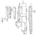
- FIG. 2 is an exploded perspective view of the mechanical-electrical integrated type shift controller 41 which best represents the characteristics of the present invention.
- a motor 16 for generating the drive force has a first gear 21 as an output stage gear mounted on a motor output shaft of the motor 16, is received into a motor receiving portion of a gear case 17, and is secured to the gear case 17 by means of a metal band 16a.
- An intermediate rotating shaft 23, a second gear 19 and a third gear 13 are molded integrally, and as materials for the intermediate rotating shaft 23, the second gear 19 and the third gear 13, iron, aluminum, resins or the like may be employed, but in the present invention, iron material which is highest in strength is employed.
- the second gear 19 is arranged so as to mesh with the first gear 21, and the third gear 13 is arranged through a gear holder 12 so as to mesh with a fourth gear 20 molded integral with an output rotating shaft 11.
- the gear mechanism is constituted as described above to thereby provide an advantage that a clearance between the gears can be made smaller than the case where the gear mechanism is constituted merely by a plane gear.
- the output rotating shaft 11 is formed at its extreme end with a counterbore, and engaged so as to transmit torque by fitting with a shift rail 54 (see FIG. 9) of the transfer case assembly 33.
- a magnet holder 10 is fitted in the upper surface of the fourth gear 20 or connected by bonding.
- a yoke 9 made of a magnetic material is connected to the magnetic holder 10 by fitting or bonding, and a magnet 8 is connected to the magnetic yoke 9 by fitting or bonding.
- the magnet 8, the magnetic yoke 9, the magnet holder 10 and the output rotating shaft 11 are all connected so as to be rotated synchronously.
- a connector 18 is molded integrally with a board case 6 also serving as a gear cover, and the connector 18 is used for communication with the shift controller outside, supply of power supply, and input of an ignition signal.
- a heatsink or radiating plate 5 is bonded to the board case 6 with an epoxy or silicone adhesive bond, and a circuit board 2 is bonded to the heatsink 5 with the epoxy or silicone adhesive bond.
- a sensor 3, a microcomputer 4, and EEPROM 24 are mounted on the circuit board 2, and a board cover 1 is bonded to the board case 6 with the epoxy or silicone adhesive bond so as to cover the circuit board 2.
- the board case 6 is connected to a gear case 17 by screwing or the like through a seal material 7.
- the circuit board 2 and the terminal of the motor 16 are electrically connected through a motor connection terminal A14 and a motor connection terminal B15.
- the gear case 17 has a motor housing portion and a gear mechanism housing portion which are a metal housing.
- the board case 6 is secured to a housing (gear case 17) which is a resin cover with the seal 7 put therebetween, both of which define a space for receiving the motor and the gear mechanism.
- the board case 6 is also provided with a function of covering the motor and the gear mechanism in which sense it can be called a motor cover or a gear cover.
- the motor and the intermediate rotating shaft may be arranged in parallel with each other, in addition to that shown in FIG. 9.
- FIG. 3 is a sectional view of a portion for detecting a rotation angle of an output rotating shaft 11.
- a magnet holder 10 is connected in contact with the output rotating shaft 11 so as to rotate synchronously with the output rotating shaft 11.
- the magnet holder 10 is provided with a groove for fixing a magnet 8 and a magnetic yoke 9 in a stabilized condition. It is desired that the magnet 8 and the magnetic yoke 9 are in contact, and in the present invention, they are bonded to each other using an epoxy adhesive bond, but the magnet 8 and the magnetic yoke 9 may be molded integrally.
- the magnet 8 and the magnetic yoke 9 are adhered to the magnet holder 10 with an epoxy adhesive bond.
- the lower surface of the board case 6 is positioned away from the upper surface of the magnet 8, as shown in FIG. 2.
- the heatsink 5 is connected to the board case 6 with an epoxy or silicone adhesive bond
- the circuit board 2 is connected to the heatsink 5 by the epoxy or silicone adhesive bond.
- the sensor element 3 is arranged within a magnetism distribution space of the magnet 8 and on the circuit board 2. In this case, it is desired that the sensor element 2 is disposed on the rotating shaft of the magnet 8, but generally, a deviation occurs due to the assembling tolerance or the like. However, if the center of the sensor element 3 is disposed within a circle of about 5 mm in diameter, it can be corrected by a calibration described later.
- a main function of the shift controller 41 is to cause the rotation angle of the output rotating shaft 11 to follow the target rotation angle. To this end, it is necessary to detect the rotation angle of the output rotating shaft 11 with high accuracy. Further, the rotation operating range of the output rotating shaft 11 is from 0 to 280 degrees, and a mechanism capable of detecting an angle over substantially whole region (360 degrees) is necessary.
- Various systems for detecting a rotation angle such as a non-contact type using a Hole element have been heretofore devised.
- the magnet 8 is secured to the output rotating shaft 11, and a change of direction of the magnetic field is detected using the sensor element 3 on the circuit board 2 to thereby realize the detection of the rotation angle over the whole region (360 degrees).
- the magnet 8 Attention should be paid generally in using the magnet to the unexpected disturbance of a magnetic circuit.
- a first gear 21, a second gear 19, a third gear 13, a fourth gear 20 and the output rotating shaft 11 are possibly formed of magnetic bodies such as iron to give unexpected influence to the magnetic circuit around the magnet 8.
- the magnet 8 is distanced to some extent from the magnetic bodies such as the first gear 21, the second gear 19, the third gear 13, the fourth gear 20 and the output rotating shaft 11.
- the magnetic body closest to the magnet 8 is the output rotating shaft 11, and with respect to coercive force 304 (KA/m) and the remanent flux density 470 (mT), the distance between the magnet 8 and the output rotating shaft 11 is 20 mm.
- the magnetic holder 10 will suffice to be a non-magnetic body, and in consideration of the processing property or the rigidity, resin or aluminum may be employed. In the present invention, the resin is employed.
- the magnetic holder 10 keeps the distance between the magnet 8 and the output rotating shaft 11 constant and further has a function of securing the magnet 8 to the shaft B11 so that the magnet 8 may be rotated in synchronism with the output rotating shaft 11. Further, the magnet holder 10 also bears a function of adjusting the distance (hereinafter referred to as the air gap) between the magnet 8 and the sensor element 3. This air gap is very important, and where the air gap is too longer than the set value, the magnetic force of the magnet 8 reaching the sensor element 3 is so small that the sensor element 3 cannot be activated.
- the magnet 8 comes in contact with the board case 6 to impair the rotational motion of the output rotating shaft 11, or the magnetic force applied to the sensor element 3 is too large that unexpected damage is possibly given to the sensor element 3.
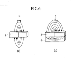
- the magnetic yoke 9 is arranged so as to come in contact with a lower part of the magnet 8 (opposite the sensor element 3) in order to realize the effective magnetic circuit (see FIG. 6B).
- the magnetic yoke 9 should be a magnetic body. Further, attention should be paid to the shape of the magnetic yoke.
- the thickness of the magnetic yoke 9 will suffice to be a thickness to a degree that the magnetic characteristic of the magnetic yoke is not saturated, and relies upon the magnetic characteristic of the magnet 8.
- the thickness of the magnetic yoke 9 with respect to the magnet 8 is desirably not less than 2 mm, and actually 3 mm is employed. It is desired that a sectional area of the magnetic yoke 9 in a direction vertical to the rotating shaft is equal to that of the magnet 8.
- the solid line represents the case where the magnetic yoke is present, and the broken line represents where the magnetic yoke is absent.
- the magnetic yoke 9 having the shape as described is employed whereby the magnetic circuit at the lower part of the magnet 8 is limited to a determined space (see FIG. 4 (b)), and the magnetic force applied to the sensor element 3 can be strengthened about 40 percent as compared with the case where the magnetic yoke 9 is absent. Accordingly, by using the magnetic yoke 9, the effective magnetic circuit can be realized.
- SUS430 is used for the magnetic yoke 9, but even the magnetic body having the magnetic characteristic equal thereto, for example, such as S45C or S15C can be applied to the present invention.
- the output of the sensor element 3 reacts in the direction of a magnetic field which passes through the sensor element 3 is not affected by the magnitude of magnetic field.
- the circuit board 2, the heatsink 5, and the board case 6 are positioned between the magnet 8 and the sensor element 3, of which thicknesses are about 1 mm, about 2 mm and about 2 mm, respectively.
- the distance from the board case 6 to the surface of the magnet 8 is set to about 1 mm, the distance between the magnet 8 and the sensor element 3 is 6 mm in total. In consideration of the election tolerance or the process tolerance, that distance is about 6 mm ⁇ 1 mm.
- material and shape of the magnet 6 are determined from the condition of distance (about 6 mm ⁇ 1 mm) and the condition of the magnetic force which passes through the sensor element 3 (10 kA/m to 15 kA/m).
- Table 1 shows the magnetic material and its characteristics being used at present.
- a SmFeN magnet which is in better conditions is employed. It is desired that the directivity of magnetic field passing through the sensor element 3 is in synchronism with the rotation of the magnet 8. Because of this, it is desired that the shape of the magnet is symmetrical about the center shaft, and as shown in FIG. 8, a disk shape, a donut shape, a trapezoidal shape, a bar-like shape or the like may be employed.
- a bar-like magnet (20 mm x 4 mm x 3 mm) is used in consideration of easiness of processing.
- FIG. 9 shows the internal constitution of the shift controller 41.
- a gear chamber 40 formed by the gear case 17 and the board case 6 are arranged mechanical portions including the rotational bodies such as the first gear 21, the second gear 19, the third gear 13, the gear holder 12, the magnet 8, the magnetic yoke 9 and the like.
- the board case 6 is arranged a board chamber 66 including the circuit board 2, the heatsink 5, the sensor element 3, the microcomputer 4 and the like so as to be isolated from the gear chamber 40 through the gear chamber 40 and the board case 6.
- FIG. 10 there is contemplated as a partitioning wall for isolating a board chamber 66 from the gear chamber 40, a combination of the board or the board case or a heatsink 56 or a gear case 55 and the board or the board case or a heatsink 56. Further, as a mounting position of a board chamber 66, there is contemplated on the rotating shaft of the final output shaft or on the rotating shaft of the intermediate gear.
- the range of operating ambient temperature of the shift controller 41 is from -40 degrees to 125 degrees.
- the operation at high temperature poses a problem, and at the time of driving the motor 16, the rise of temperature of the circuit board 2 is expected.
- the heatsink 5 is disposed between the board case 6 and the circuit board 2.
- the purpose of arranging the heatsink 5 is for the measure for radiation, but simultaneously bears a function of a reinforcing material for the circuit board 2. Accordingly, as the material for the heatsink 5, those having high heat conductivity and high strength are desirable.
- the heatsink 5 is disposed between the magnet 8 and the sensor element 3, and should not impair the magnetic circuit. Therefore, the heatsink 5 need be a non-magnetic body which does not affect on the magnetic circuit.
- aluminum (Al) is employed as material for the heatsink 5 in consideration of the foregoing conditions.
- the circuit board 2 is arranged between the magnet 8 and the sensor element 3 not to impair the magnetic circuit. Therefore, a material for the circuit board 2 is a non-magnetic body similar to the heatsink 5. Furthermore, in order to effectively radiate heat generated on the circuit board 2, the material is necessary to be high in heat conductivity. In the present invention, aluminum (Al 2 O 3 ) is employed.
- FIG. 11 shows an arrangement of circuit parts on a circuit board 2. On the circuit board 2 are arranged a microcomputer 4, a sensor element 3, an amplifier 45, a motor drive circuit element 47, EEPROM 24, a regulator 49 and the like. These are connected to electrically one another and bear the control of the shift controller.
- the position of the microcomputer 4 is not particularly regulated but any position will suffice as long as it is on the circuit board 2.
- the microcomputer 4 is operated in accordance with a predetermined program, and bears a function of deciding and controlling the operation of the shift controller.
- the concrete functions of the shift controller involve communication with the engine controller, output signal processing of the sensor element 3 described later, control of the motor 16 and the like.
- the microcomputer 4 or the circuit board 2 on which the microcomputer 4 is arranged need to provide a PWM output/sensor element signal for the motor control, and an A/D input for input of a target angle signal.
- H85/261 made by Hitachi Seisakusho is used as the microcomputer 4.
- the microcomputer 4 is provided with functions of an electrically re-writable flush memory, an A/D conversion input, a timer and the like.
- the position of the sensor element 3 is within the magnetic distribution space of the magnet 8 and on the rotating shaft of the output rotating shaft 11, and it is desired that the arrangement surface of the sensor element 3 is parallel with the rotational surface of the magnet 8.
- a deviation is present in both coaxiality and parallelism.
- the deviation of both coaxiality and parallelism is one of causes that cannot be ignored of affecting on the output of the sensor element 3.
- the sensor element calibration described later is carried out in all the shift controller in order to remove the aforementioned influence.
- FIG. 12 shows a circuit function block on the circuit board. Since the amplitude of an output signal of a sensor element 3 is approximately 100 mV (at the time of 5 V supply), it is necessary for detecting an angle with higher accuracy to amplify the output signal of the sensor element 3 to input it into the microcomputer 4. To this end, the amplifier 45 bears a function of amplifying the output of the sensor element 3 to output it to the microcomputer 4.
- the EEPROM 24 is used to store constant calculated in the sensor element calibration or to record the conditions of the shift controller 41.
- the motor drive circuit element 47 comprises a H bridge circuit, and causes drive current to flow to the motor 16 in response to a motor drive command signal such as PWM output by the microcomputer 4.
- One of the characteristics of the present invention lies in that on the circuit board 2 are arranged all circuit parts such as the microcomputer 4, the sensor element 3, the amplifier 45, the motor drive circuit element 47, the EEPROM 24, the regulator 49 and the like.
- This enables planning not only reduction of the number of parts such that a wiring between the sensor element 3 and the microcomputer 4, but also enhancement of reliability.
- exclusive mounting members for the sensor element need not be provided, and simplification of the sensing portion, reduction in the board size, and reduction in the shift controller size can be planned.
- a material for the board is aluminum, all or some of ICs can be mounted in the state of the paired chips.
- the regulator 49, the amplifier 45, the motor drive circuit element 47, and the lamp drive IC 50 are mounted in a bear-chip manner.
- a board cover 1 is provided over the circuit board 2.
- the circuit board 2 is protected from the external causes such as water, dust or oil by the board case 6 and the board cover 1.
- a board chamber 66 a space in which the circuit board 2 is stored and arranged
- internal air of the base late chamber 66 is inflated, but at low temperature, it is contracted.
- ventilation becomes disabled, and stress caused by inflation and contraction of air is applied to the board cover 1 and the board case 6.
- the board cover 1 or the board case 6 is probably broken due to the stress. Only the means for solving this problem is to provide a ventilation portion in the board case 6 or the board cover 1.
- the desirable conditions of the ventilation portion is excellent in water resistance, repelling properties, oil resistance, and heat resistance, and are able to realize stabilized and continuous ventilation.
- a ventilation portion 43 having a diameter of 1 mm is provided on the board cover 1, and a seal material having a porous construction is attached so as to cover the ventilation portion 43.
- the motor drive current and the motor 16 on the circuit board 2 have to be connected electrically.
- a conductor is used.
- the circuit board 2 and the motor 16 have to be joined newly by soldering or the like, which is not desirable in terms of work efficiency. Therefore, for connection of the circuit board 2 and the motor 16, fitting joining using an exclusive-use terminal or the like is desired.
- the construction in which the motor connection terminal A14 and the motor connection terminal B15 are molded integrally with the board case 6, which is fitted and joined to the motor terminal is employed, for simplifying the assembling process, the construction in which the motor connection terminal A14 and the motor connection terminal B15 are molded integrally with the board case 6, which is fitted and joined to the motor terminal. This is a devise that after the circuit portion 25 and the mechanical portion 26 have been combined, both the portions are merely combined together whereby the circuit board 2 and the motor 16 are connected to each other (see FIGS. 4A, 4B and 13).
- one characteristic is the arrangement constitution of the motor and the gear.
- portions which require extreme time and technique are assembling and mounting steps of the motor and the gear.
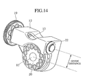
- FIG. 14 shows the constitution of a gear set.
- the gear holder 12 has two through-holes for bearings.
- the intermediate rotating shaft 23 integral with the second gear 19 and the third gear 13 is fitted and connected in one through-hole, and fixed axially by means of the clip 22.
- the output rotating shaft 11 integral with the fourth gear 20 is fitted and connected in the other through-hole.
- the motor size is in a proportional relation with the motor output torque, and torque enough to drive the transfer case 33 by the output rotating shaft 11 cannot be obtained merely by making the motor size small. Therefore, one or a plurality of gear stages, and torque generated in the motor 16 is amplified and transmitted to the output rotating shaft 11 through the gear stages. In a case of only one gear stage, the gear size of the rear stage becomes large, which is not desirable in terms of miniaturization of the shift controller 41. Accordingly, there is desired a method in which a plurality of gear stages are provided to dispose the gears efficiently whereby target torque in the output rotating shaft 11 is obtained.
- the present embodiment employs a devise that the distance between the axial centers of the third gear 13 and the fourth gear 20 can be maintained constant by using the gear holder 12. Furthermore, the third gear 13 and the fourth gear 20 are incorporated into the gear holder 12 in advance, and the gear set is formed into module whereby the step when the gears are incorporated into the gear case 17 becomes easy.
- FIG. 15 shows a block diagram of the sensor element calibration.
- the output rotating shaft 11 of the shift controller 123 and the rotary encoder 116 capable of detecting an angle to be a reference are arranged so that their rotating shafts are coaxial.
- the motor 16 within the shift controller 116 is driven to rotate the output rotating shaft 11, and simultaneously, a absolute angle signal from the encoder and an output of the angle sensor element 3 are placed in synchronism with each other and read into a computer (117).
- noises of the output signal of the sensor element 3 are removed (118), and normalization is accomplished so that the output of the sensor element 3 is 1 in maximum, and -1 in minimum (109).
- FIG. 16 shows a relation between the magnet rotation angle and the normalized signal.
- the sensor element 3 employed in the present embodiment has outputs of two systems, and the output signals are signals which are deviated in phase each other with respect to the direction of magnetic field passing through the sensor element 3.
- the output signal of the sensor element 3 with respect to the magnet rotation angle is divided into four regions using normalized two signals and two thresholds (120). Table 2 shows the respective regions and conditions.
- the threshold level 1 is smaller than the value in which the output 1 and the output 2 cross on the positive side
- the threshold level 2 is larger than the value in which the output 1 and the output 2 cross on the negative side.
- the threshold level 1 is set to 0.6, and the threshold level 2 to -0.6.
- ⁇ indicates the absolute angle calculated from the encoder output
- ⁇ indicates the variable used in the above-described calculation in each region, which is displayed by the bold line in FIG. 16.
- n indicates the sampling number in each region
- Xi indicates the i-th value of variable X.
- the coefficients to be calculated are 16 in total. Finally, the calculated coefficients are written into EEORIN 24 within the shift controller 123 and saved (122).
- the temperature characteristics of the sensor element and the compensation method thereof will be mentioned.
- the reactivity with respect to the object or its own resistance value changes with temperatures (temperature-dependent).
- the range of the operating temperature of the shift controller is from -40 degrees to 125 degrees. Further, it is expected that the temperature conditions excess the above results momentarily. The influence given to the sensor element by the wide temperature change cannot be ignored, and need be compensated for by any means.
- the sensor element output is subjected to calibration, and the sensor output is calculated using the calculated constant.
- a offset . a amp is constant obtained by experiments or the like
- t calibration is a temperature when calibration is carried out
- t is temperature around the sensor element
- v offsetcomp are values for which temperature characteristics of sensor element 3 output means value and amplitude are compensated for
- V max ⁇ V min are maximum value and minimum value of the sensor element 3 output when calibration is executed.
- the circuit of FIG. 17 is used for the temperature sensor element to obtain an output corresponding to the temperature.
- the output of the temperature sensor is input into a computer such as a microcomputer to compute temperatures. If the output of the temperature sensor element has linearity with respect to the temperature, the temperature is calculated by a simple computation. However, actually, the temperature range in which the relation between the temperature and the temperature sensor element output has linearity is limited, and non-linearity results in the range of operating temperature of the shift controller. Calculation of temperature by concrete methods as mentioned below is contemplated.
- the B constant of a thermister is of a non-linear type with respect to an output (v temp ) of the temperature sensor element, which is linear approximated by the minimum square method.
- the second method is a table method.
- a corresponding table of the actual temperature and the temperature sensor element output is prepared in advance, and the present temperature sensor element output and this corresponding table are used, and a temperature is calculated by a linear complement or a tertiary complement.
- the third method is an approximation method by way of a tertiary function.
- the actual temperature and the temperature sensor element output are approximated by a tertiary function, and its constant is stored or recorded.
- the temperature is calculated using the output of the temperature sensor element and the coefficient of the tertiary function.
- the region is divided into some regions by the temperature sensor element output, and the actual temperature and the temperature sensor element output are approximated by the tertiary function every region, which coefficient is stored or recorded.
- the region is discriminated by the output of the temperature sensor element, and further, the temperature is calculated using the coefficient of the tertiary in that region and the output of the temperature sensor element (see Expression 9). In the present embodiment, the latter method is employed.
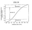
- the temperature sensor element output is divided into three regions according to the temperature sensor element output.
- the region dividing conditions and the coefficients ⁇ of the tertiary function approximated in the respective regions are given in Table 3.
- v tn is a value normalized so that the maximum value is 1 and the minimum value is -1 of the temperature sensor element output.
- FIG. 19 shows the process for calculating the rotation angle from the output of the sensor element 3.
- Signals of two systems corresponding to the rotation angle of the magnet are output through the amplifier from the non-contact sensor while being affected by the magnetic circuit around the magnet irrespective whether or not the motor is driven.
- Noise components such as a periodical noise generated form the motor are sometimes included in the output signal of the amplifier, and where the noise components cannot be ignored, it is necessary to remove the noise components.
- a lowpass filter is provided on the output stage of the amplifier in order to remove the noises.
- a signal having passed through the lowpass filter is input into a computer such as the microcomputer 4. Therefore, it is necessary that a computer or an electronic circuit be provided with an analog input function. Further, a higher-order filter can be provided even within the computer.
- a digital filter such as FIR or IIR
- the noise components can be removed more effectively.
- a lowpass filter cutoff frequency; 1 kHz
- a region is decided by the value of the temperature sensor (105).
- a temperature is calculated using the coefficient in each region calculated previously (106).
- an output mean value of the sensor element 3 is compensated for the temperature characteristic from the signal from which noise was removed and the calculated temperature (107).
- ⁇ indicates the calculated rotation angle
- ⁇ a, b, c, d ⁇ indicates one belonging to the selected region out of the coefficients of the tertiary function calculated by calibration
- v indicates one value that should be used for computation out of the normalized signals of two systems.
- a torque command value given to the motor is calculated from the calculated present shaft rotation angle (111) and target rotation angle information (112) obtained from a mode selection signal.
- Various calculation methods are adopted for this calculation. In the following, there is defined that an angle increases in the right direction of rotation.
- the torque command value given to the motor has three types, i.e., constant on the positive side, zero, and constant on the negative sides.
- the motor is rotated in the right direction at a determined Duty ratio, or where the shaft rotation angle is larger than the target rotation angle, the motor is rotated in the left direction at a determined Duty ratio. Then, when registered or reached near, torque is set to zero.
- inertia of the motor or the output shaft is not sufficiently large, even if the torque given to the motor is set to zero, the phenomenon that the motor continues to operate with the inertia force occurs probably. As a result, the shaft rotation angle becomes enabled to stop or stand still within the target position deviation.
- a deviation between the target shaft rotation angle and the present shaft rotation angle, differentiation of time and integration up to the time are computed, the weight is applied and the arithmetic sum is taken to provide the target value of the torque given to the motor.
- This is generally called a PID control.
- the rotation angle of the shaft is controlled, and in such a case, an integrator is included in the control object, because of which it is known in the control rule that the integrator is not necessary. Therefore, in the present embodiment, the PD control is to be employed.
- the constitution of the sensor mechanism for detecting the rotating position of 360 degrees of the output rotating shaft is simplified.
- the resolution of the sensor is not affected by the gear ratio.
- the continuous angle detection becomes enabled.
- the distance between the rotational body and the sensor element can be made not less than 3 mm, and management of the distance between the rotational body and the sensor element becomes easy.
- the generated magnetic flux of the magnet is effectively utilized, and no attenuation of magnetic flux occurs, because of which an inexpensive magnet can be used, and assembling becomes simple.
- the sensor output is unsusceptible to the temperature around the sensor element, and accordingly, a problem that the resolution is deteriorated due to the change in temperature is eliminated.
- the sensor mechanism is simple.
Landscapes
- Engineering & Computer Science (AREA)
- Physics & Mathematics (AREA)
- General Physics & Mathematics (AREA)
- General Engineering & Computer Science (AREA)
- Power Engineering (AREA)
- Mechanical Engineering (AREA)
- Microelectronics & Electronic Packaging (AREA)
- Gear-Shifting Mechanisms (AREA)
- Measurement Of Length, Angles, Or The Like Using Electric Or Magnetic Means (AREA)
- Control Of Transmission Device (AREA)
- Arrangement And Mounting Of Devices That Control Transmission Of Motive Force (AREA)
- Motor Or Generator Frames (AREA)
- Measuring Or Testing Involving Enzymes Or Micro-Organisms (AREA)
Priority Applications (1)
| Application Number | Priority Date | Filing Date | Title |
|---|---|---|---|
| EP07002941A EP1777440A3 (fr) | 2001-12-21 | 2002-12-20 | Module de commande d'un arbre rotatif de sortie et module de changement d'une condition de conduite pour automobile |
Applications Claiming Priority (2)
| Application Number | Priority Date | Filing Date | Title |
|---|---|---|---|
| JP2001388685A JP3799270B2 (ja) | 2001-12-21 | 2001-12-21 | 自動車の駆動状態を切り換える為の制御装置 |
| JP2001388685 | 2001-12-21 |
Related Child Applications (1)
| Application Number | Title | Priority Date | Filing Date |
|---|---|---|---|
| EP07002941A Division EP1777440A3 (fr) | 2001-12-21 | 2002-12-20 | Module de commande d'un arbre rotatif de sortie et module de changement d'une condition de conduite pour automobile |
Publications (3)
| Publication Number | Publication Date |
|---|---|
| EP1323956A2 true EP1323956A2 (fr) | 2003-07-02 |
| EP1323956A3 EP1323956A3 (fr) | 2005-03-02 |
| EP1323956B1 EP1323956B1 (fr) | 2007-05-30 |
Family
ID=19188199
Family Applications (2)
| Application Number | Title | Priority Date | Filing Date |
|---|---|---|---|
| EP07002941A Withdrawn EP1777440A3 (fr) | 2001-12-21 | 2002-12-20 | Module de commande d'un arbre rotatif de sortie et module de changement d'une condition de conduite pour automobile |
| EP02028723A Expired - Lifetime EP1323956B1 (fr) | 2001-12-21 | 2002-12-20 | Module de commande d'un arbre rotatif de sortie et module de changement d'une condition de conduite pour automobile |
Family Applications Before (1)
| Application Number | Title | Priority Date | Filing Date |
|---|---|---|---|
| EP07002941A Withdrawn EP1777440A3 (fr) | 2001-12-21 | 2002-12-20 | Module de commande d'un arbre rotatif de sortie et module de changement d'une condition de conduite pour automobile |
Country Status (4)
| Country | Link |
|---|---|
| US (3) | US6931957B2 (fr) |
| EP (2) | EP1777440A3 (fr) |
| JP (1) | JP3799270B2 (fr) |
| DE (1) | DE60220364T2 (fr) |
Cited By (10)
| Publication number | Priority date | Publication date | Assignee | Title |
|---|---|---|---|---|
| WO2006074756A1 (fr) * | 2005-01-13 | 2006-07-20 | Zf Friedrichshafen Ag | Boite de vitesses de vehicule a moteur electrique integre |
| WO2008012149A1 (fr) * | 2006-07-28 | 2008-01-31 | Robert Bosch Gmbh | Élément d'entraînement intégré |
| EP1640204A3 (fr) * | 2004-09-23 | 2008-10-01 | Siemens AG Österreich | Actionneur électro-mécanique pour boîte de vitesse d'une véhicule |
| EP1998081A3 (fr) * | 2007-05-31 | 2012-09-12 | Hitachi Ltd. | Machine et contrôleur de commutation de type d'intégration électrique |
| CN103607069A (zh) * | 2013-11-19 | 2014-02-26 | 朱萱 | 一种以磁体和霍尔传感器作为检测元件的摆动驱动装置 |
| EP1817548B1 (fr) * | 2004-12-02 | 2015-06-03 | Honeywell International Inc. | Capteur de dent d'engrenage adaptatif avec detecteurs de cretes doubles et capacite de mise sous tension effective |
| CN104704717A (zh) * | 2012-10-01 | 2015-06-10 | 三菱电机株式会社 | 电动驱动装置 |
| EP2980524A4 (fr) * | 2013-03-29 | 2016-11-23 | Nippon Seiki Co Ltd | Dispositif de détection de position de vitesse |
| WO2017186211A1 (fr) * | 2016-04-28 | 2017-11-02 | Schaeffler Technologies AG & Co. KG | Procédé de linéarisation de signaux d'un module de réception de champ magnétique |
| SE1751414A1 (en) * | 2017-11-15 | 2019-05-16 | Stegia Ab | Controlled electric motor |
Families Citing this family (55)
| Publication number | Priority date | Publication date | Assignee | Title |
|---|---|---|---|---|
| JP4244561B2 (ja) * | 2001-07-10 | 2009-03-25 | ヤマハ株式会社 | 方位測定機能を有する携帯型電子装置 |
| KR100914373B1 (ko) * | 2002-03-27 | 2009-08-28 | 아이신에이더블류 가부시키가이샤 | 시프트 위치 검출 장치를 갖는 제어 장치 및 이를 구비한 파워트레인 |
| JP4391065B2 (ja) * | 2002-08-23 | 2009-12-24 | 愛三工業株式会社 | スロットル開度検出装置 |
| JP2005028940A (ja) * | 2003-07-09 | 2005-02-03 | Toyoda Mach Works Ltd | 駆動力伝達制御装置 |
| JP4413592B2 (ja) * | 2003-12-12 | 2010-02-10 | パナソニック株式会社 | 回転角度検出装置 |
| EP1561609B1 (fr) * | 2004-02-06 | 2006-07-05 | C.R.F. Società Consortile per Azioni | Capteur de température pour pièces rotatives et méthode de détection de la température correspondante |
| DE102005040647A1 (de) * | 2005-08-27 | 2007-03-08 | Valeo Systèmes d`Essuyage | Elektromotorischer Hilfsantrieb für Fahrzeuge |
| JP2007076614A (ja) * | 2005-09-16 | 2007-03-29 | Denso Corp | 車両用盗難防止装置 |
| DE102005061285A1 (de) * | 2005-12-20 | 2007-06-21 | Lemförder Electronic GmbH | Wähleinrichtung zum Schalten eines Fahrzeuggetriebes |
| DE102006060213B4 (de) * | 2005-12-30 | 2014-05-28 | Asm Automation Sensorik Messtechnik Gmbh | Drehwinkelsensor |
| US7598877B2 (en) * | 2006-05-30 | 2009-10-06 | The Goodyear Tire & Rubber Company | Transponder carrier for a tire |
| JP5147213B2 (ja) * | 2006-10-11 | 2013-02-20 | 日立オートモティブシステムズ株式会社 | インダクタンス式回転角度検出装置及びそれを備えたモータ駆動式の絞り弁制御装置 |
| US10704933B2 (en) | 2014-09-02 | 2020-07-07 | Infineon Technologies Ag | Integrated angle sensing device |
| JP5333811B2 (ja) * | 2007-07-26 | 2013-11-06 | 株式会社大一商会 | パチンコ遊技機 |
| DE102007063694A1 (de) * | 2007-09-25 | 2010-09-09 | Magna Powertrain Ag & Co Kg | Getriebeinheit |
| GB2453580B (en) * | 2007-10-11 | 2012-06-06 | Dall Production Aps | A Rotary encoder |
| NL2001188C2 (nl) * | 2008-01-15 | 2009-07-16 | Mci Mirror Controls Int Nl Bv | Aandrijving, alsmede aandrijfsysteem. |
| ITBO20080595A1 (it) * | 2008-09-30 | 2010-04-01 | Cnh Italia Spa | Trasmissione variabile continua |
| US7887065B2 (en) * | 2009-02-24 | 2011-02-15 | Hadley Products | Height control valve for vehicle leveling system |
| DE102009014595A1 (de) | 2009-03-24 | 2010-09-30 | Magna Powertrain Ag & Co Kg | Getriebeeinheit |
| JP5515418B2 (ja) * | 2009-05-25 | 2014-06-11 | トヨタ自動車株式会社 | ブレーキ制御装置 |
| JP5263024B2 (ja) | 2009-06-18 | 2013-08-14 | 株式会社日立製作所 | 回転角検出装置および回転速度検出装置 |
| JP5066142B2 (ja) | 2009-06-18 | 2012-11-07 | 日立オートモティブシステムズ株式会社 | インダクティブ型スロットルセンサ付きモータ駆動型スロットルバルブ装置、およびモータ駆動型スロットルバルブ装置のスロットルシャフトの回転角度を検出するためのインダクティブ型スロットルセンサ |
| DE102009042506B3 (de) * | 2009-09-22 | 2011-06-16 | Asm Automation Sensorik Messtechnik Gmbh | Verwendung eines Bandsensors zur Positionsbestimmung im Inneren eines Behälters |
| CH702193A2 (de) * | 2009-11-05 | 2011-05-13 | Polycontact Ag | Positionsmeldeeinrichtung. |
| JP5096442B2 (ja) | 2009-11-17 | 2012-12-12 | 株式会社日立製作所 | 回転角計測装置,モータシステム及び電動パワーステアリング・システム |
| JP2011127909A (ja) * | 2009-12-15 | 2011-06-30 | Alps Electric Co Ltd | 回転検出システム |
| US20110186758A1 (en) * | 2010-02-01 | 2011-08-04 | Calbrandt, Inc. | Hydraulic Motor With Non-Contact Encoder System |
| JP5066600B2 (ja) * | 2010-11-22 | 2012-11-07 | 日立オートモティブシステムズ株式会社 | 機電一体型シフトコントローラ |
| US9488496B2 (en) * | 2012-09-13 | 2016-11-08 | Bourns, Inc. | Position measurement using flux modulation and angle sensing |
| JP6310189B2 (ja) * | 2013-05-29 | 2018-04-11 | Dmg森精機株式会社 | 回転角度指令値の補正方法 |
| CN103363100B (zh) * | 2013-07-25 | 2016-03-30 | 长城汽车股份有限公司 | 车辆以及用于车辆的自动换挡电路 |
| US9529060B2 (en) | 2014-01-09 | 2016-12-27 | Allegro Microsystems, Llc | Magnetoresistance element with improved response to magnetic fields |
| CN103825408A (zh) | 2014-02-28 | 2014-05-28 | 深圳市大疆创新科技有限公司 | 电机、应用电机的云台和应用云台的拍摄装置 |
| KR102249031B1 (ko) * | 2014-03-26 | 2021-05-07 | 섀플러 테크놀로지스 아게 운트 코. 카게 | 자동차 변속기용 변속기 액추에이터 |
| JP2016061713A (ja) * | 2014-09-19 | 2016-04-25 | 日本精工株式会社 | 回転角度センサ及びそれを備えたブラシレスモータ並びにそれを搭載した電動パワーステアリング装置及び車両 |
| JP6578642B2 (ja) | 2014-09-30 | 2019-09-25 | 日本電産株式会社 | モータ |
| JP6435754B2 (ja) | 2014-09-30 | 2018-12-12 | 日本電産株式会社 | モータ |
| JP6520033B2 (ja) | 2014-09-30 | 2019-05-29 | 日本電産株式会社 | モータ |
| JP6368936B2 (ja) | 2014-09-30 | 2018-08-08 | 日本電産株式会社 | モータ |
| JP6569306B2 (ja) | 2014-09-30 | 2019-09-04 | 日本電産株式会社 | モータ |
| JP6398549B2 (ja) * | 2014-09-30 | 2018-10-03 | 日本電産株式会社 | モータ |
| AU2015335646B2 (en) | 2014-10-24 | 2018-11-08 | Moog Inc. | Position sensor assembly |
| WO2016196157A1 (fr) | 2015-06-05 | 2016-12-08 | Allegro Microsystems, Llc | Élément de magnétorésistance à vanne de spin à réponse améliorée aux champs magnétiques |
| US11078997B2 (en) * | 2015-07-20 | 2021-08-03 | National Machine Group | Motor driven electromechanical actuator |
| US10620279B2 (en) | 2017-05-19 | 2020-04-14 | Allegro Microsystems, Llc | Magnetoresistance element with increased operational range |
| US11022661B2 (en) | 2017-05-19 | 2021-06-01 | Allegro Microsystems, Llc | Magnetoresistance element with increased operational range |
| JP6950545B2 (ja) * | 2018-01-19 | 2021-10-13 | 株式会社デンソー | シフトレンジ制御装置 |
| JP2019193516A (ja) * | 2018-04-27 | 2019-10-31 | ソニーモバイルコミュニケーションズ株式会社 | 駆動装置および駆動制御方法 |
| JP7018045B2 (ja) | 2019-09-06 | 2022-02-09 | ジェコー株式会社 | アクチュエータ及び排気バルブ駆動装置 |
| EP3885698B1 (fr) * | 2020-01-31 | 2022-09-28 | NSK Ltd. | Procédé et dispositif d'étalonnage pour dispositif de calcul d'angle de rotation, dispositif de calcul d'angle de rotation, équipement de commande de moteur, produit actionneur électrique et appareil de direction assistée électrique |
| US11698309B2 (en) * | 2020-03-05 | 2023-07-11 | Delta Electronics, Inc. | Linear actuator |
| KR102506089B1 (ko) * | 2020-12-10 | 2023-03-03 | 현대오토에버 주식회사 | 교번 프리휠링을 위한 모터 제어 장치 및 모터의 교번 프리휠링 제어 방법 |
| DE102021212359A1 (de) | 2021-11-03 | 2023-05-04 | Zf Friedrichshafen Ag | Stator mit einer Tilgermasse sowie elektrischer Antriebsstrang mit dem Stator |
| US11719771B1 (en) | 2022-06-02 | 2023-08-08 | Allegro Microsystems, Llc | Magnetoresistive sensor having seed layer hysteresis suppression |
Citations (2)
| Publication number | Priority date | Publication date | Assignee | Title |
|---|---|---|---|---|
| JPH1194512A (ja) | 1997-07-26 | 1999-04-09 | Koninkl Philips Electron Nv | 角度センサー、位置センサー及び自動車 |
| US6155126A (en) | 1999-10-18 | 2000-12-05 | Borgwarner Inc. | Integrated shift motor and electronic controller |
Family Cites Families (32)
| Publication number | Priority date | Publication date | Assignee | Title |
|---|---|---|---|---|
| GB1307985A (en) * | 1969-04-18 | 1973-02-21 | Sybrook Electronics Ltd | Inductive transducers |
| US4125821A (en) * | 1977-08-05 | 1978-11-14 | Denki Onkyo Company, Limited | Potentiometer providing a non-linear output |
| JPS54148578A (en) * | 1978-04-18 | 1979-11-20 | Nec Corp | Rotating direction detector |
| US4415856A (en) * | 1981-01-19 | 1983-11-15 | General Electric Company | Rotatable magnetic field-sensing solid-state switch apparatus |
| JPS58106971U (ja) * | 1982-01-14 | 1983-07-21 | 棚沢 日佐司 | プリント配線基板 |
| US5122741A (en) * | 1989-12-06 | 1992-06-16 | Alps Electric Co., Ltd. | Holding members for sensor and wiring members of magnetic rotary encoder |
| FR2715726B1 (fr) | 1994-02-01 | 1996-10-18 | Moving Magnet Tech | Capteur magnétique de position à sonde de Hall. |
| IT1250522B (it) * | 1991-12-11 | 1995-04-08 | Fiat Auto Spa | Dispositivo di comando per un cambio di velocita' per autoveicoli. |
| JPH05215505A (ja) * | 1992-02-05 | 1993-08-24 | Mitsubishi Electric Corp | 位置検出装置 |
| US6198275B1 (en) * | 1995-06-07 | 2001-03-06 | American Electronic Components | Electronic circuit for automatic DC offset compensation for a linear displacement sensor |
| JPH0639330A (ja) | 1992-07-23 | 1994-02-15 | Nec Corp | 薬液塗布装置 |
| US5361650A (en) * | 1993-02-23 | 1994-11-08 | Eaton Corporation | Transmission having externally mounted electronic control unit |
| JPH07190803A (ja) | 1993-12-27 | 1995-07-28 | Tokyo Cosmos Electric Co Ltd | 磁気的角度センサ |
| WO1996016316A1 (fr) * | 1994-11-22 | 1996-05-30 | Robert Bosch Gmbh | Systeme de determination sans contact de l'angle de rotation d'un element rotatif |
| GB2309494B (en) * | 1995-09-12 | 2000-04-19 | Luk Getriebe Systeme Gmbh | Motor vehicle with an apparatus for the actuation of the torque transmitting system and of the transmission |
| US5845544A (en) * | 1996-07-15 | 1998-12-08 | Eaton Corporation | Control module |
| JP3685915B2 (ja) | 1997-11-18 | 2005-08-24 | アスモ株式会社 | モータ装置 |
| JPH11190606A (ja) | 1997-12-25 | 1999-07-13 | Muscle Kk | 回転量測定方法および回転量測定装置 |
| JP4385413B2 (ja) * | 1998-08-26 | 2009-12-16 | アイシン精機株式会社 | 2輪・4輪駆動切換装置 |
| DE19852502A1 (de) * | 1998-11-13 | 2000-05-18 | Philips Corp Intellectual Pty | Verfahren zur Offset-Kalibrierung eines magnetoresistiven Winkelsensors |
| US6191579B1 (en) * | 1998-12-01 | 2001-02-20 | Visteon Global Technologies, Inc. | Rotary position sensor with redundant sensing |
| US6326781B1 (en) * | 1999-01-11 | 2001-12-04 | Bvr Aero Precision Corp | 360 degree shaft angle sensing and remote indicating system using a two-axis magnetoresistive microcircuit |
| US6445178B1 (en) * | 1999-02-24 | 2002-09-03 | Donnelly Corporation | Vehicular magnetic displacement sensor for determining an offset in the output of the sensor |
| JP3568415B2 (ja) | 1999-03-30 | 2004-09-22 | アスモ株式会社 | パワーウィンドウ装置のモータユニット |
| US6166391A (en) * | 1999-05-21 | 2000-12-26 | General Electric Company | Uranium oxide shipping container |
| DE10082050D2 (de) | 1999-07-14 | 2002-05-02 | Luk Lamellen & Kupplungsbau | Getriebevorrichtung mit Schalteinrichtung |
| JP3491577B2 (ja) * | 1999-10-27 | 2004-01-26 | 株式会社デンソー | 回転角検出装置 |
| DE10009173A1 (de) * | 2000-02-26 | 2001-09-06 | Bosch Gmbh Robert | Messvorrichtung zur berührungslosen Erfassung eines ferromagnetischen Gegenstandes |
| DE10010636A1 (de) * | 2000-03-03 | 2001-09-27 | Siemens Ag | Elektromechanische Verstelleinheit für Verteilergetriebe |
| US6744639B1 (en) * | 2000-05-05 | 2004-06-01 | Jds Uniphase Corporation | Internal electromagnetic radiation shield with ground connection for removable small form factor transceivers |
| US6753680B2 (en) * | 2000-11-29 | 2004-06-22 | Ronald J. Wolf | Position sensor |
| US7208939B2 (en) * | 2001-02-28 | 2007-04-24 | Bvr Technologies Co. | Methods and apparatus for sensing angular position and speed of a rotatable shaft utilizing linearized annular magnet and commutated ratiometric hall sensors |
-
2001
- 2001-12-21 JP JP2001388685A patent/JP3799270B2/ja not_active Expired - Fee Related
-
2002
- 2002-12-20 EP EP07002941A patent/EP1777440A3/fr not_active Withdrawn
- 2002-12-20 EP EP02028723A patent/EP1323956B1/fr not_active Expired - Lifetime
- 2002-12-20 DE DE60220364T patent/DE60220364T2/de not_active Expired - Lifetime
- 2002-12-23 US US10/325,883 patent/US6931957B2/en not_active Expired - Lifetime
-
2005
- 2005-05-19 US US11/132,178 patent/US7215115B2/en not_active Expired - Lifetime
-
2007
- 2007-05-02 US US11/743,206 patent/US7427860B2/en not_active Expired - Fee Related
Patent Citations (2)
| Publication number | Priority date | Publication date | Assignee | Title |
|---|---|---|---|---|
| JPH1194512A (ja) | 1997-07-26 | 1999-04-09 | Koninkl Philips Electron Nv | 角度センサー、位置センサー及び自動車 |
| US6155126A (en) | 1999-10-18 | 2000-12-05 | Borgwarner Inc. | Integrated shift motor and electronic controller |
Cited By (18)
| Publication number | Priority date | Publication date | Assignee | Title |
|---|---|---|---|---|
| EP1640204A3 (fr) * | 2004-09-23 | 2008-10-01 | Siemens AG Österreich | Actionneur électro-mécanique pour boîte de vitesse d'une véhicule |
| EP1817548B1 (fr) * | 2004-12-02 | 2015-06-03 | Honeywell International Inc. | Capteur de dent d'engrenage adaptatif avec detecteurs de cretes doubles et capacite de mise sous tension effective |
| US7798032B2 (en) | 2005-01-13 | 2010-09-21 | Zf Friedrichshafen Ag | Vehicle gearbox with an integrated electric motor |
| CN101103218B (zh) * | 2005-01-13 | 2010-04-14 | 腓特烈斯港齿轮工厂股份公司 | 带有集成的电动机的车辆变速器 |
| WO2006074756A1 (fr) * | 2005-01-13 | 2006-07-20 | Zf Friedrichshafen Ag | Boite de vitesses de vehicule a moteur electrique integre |
| US7755248B2 (en) | 2006-07-28 | 2010-07-13 | Robert Bosch Gmbh | Integrated drive element |
| WO2008012149A1 (fr) * | 2006-07-28 | 2008-01-31 | Robert Bosch Gmbh | Élément d'entraînement intégré |
| EP1998081A3 (fr) * | 2007-05-31 | 2012-09-12 | Hitachi Ltd. | Machine et contrôleur de commutation de type d'intégration électrique |
| CN104704717A (zh) * | 2012-10-01 | 2015-06-10 | 三菱电机株式会社 | 电动驱动装置 |
| EP2905876A4 (fr) * | 2012-10-01 | 2016-06-08 | Mitsubishi Electric Corp | Appareil de pilotage électrique |
| US9627944B2 (en) | 2012-10-01 | 2017-04-18 | Mitsubishi Electric Corporation | Electric drive apparatus |
| CN104704717B (zh) * | 2012-10-01 | 2017-10-24 | 三菱电机株式会社 | 电动驱动装置 |
| EP2980524A4 (fr) * | 2013-03-29 | 2016-11-23 | Nippon Seiki Co Ltd | Dispositif de détection de position de vitesse |
| CN103607069A (zh) * | 2013-11-19 | 2014-02-26 | 朱萱 | 一种以磁体和霍尔传感器作为检测元件的摆动驱动装置 |
| WO2017186211A1 (fr) * | 2016-04-28 | 2017-11-02 | Schaeffler Technologies AG & Co. KG | Procédé de linéarisation de signaux d'un module de réception de champ magnétique |
| SE1751414A1 (en) * | 2017-11-15 | 2019-05-16 | Stegia Ab | Controlled electric motor |
| WO2019098909A1 (fr) | 2017-11-15 | 2019-05-23 | Stegia Ab | Moteur pas-à-pas électrique commandé à étage d'engrenage |
| EP3711145A4 (fr) * | 2017-11-15 | 2020-12-30 | Stegia Ab | Moteur pas-à-pas électrique commandé à étage d'engrenage |
Also Published As
| Publication number | Publication date |
|---|---|
| EP1323956B1 (fr) | 2007-05-30 |
| US6931957B2 (en) | 2005-08-23 |
| EP1323956A3 (fr) | 2005-03-02 |
| US20030135314A1 (en) | 2003-07-17 |
| EP1777440A2 (fr) | 2007-04-25 |
| US20050236219A1 (en) | 2005-10-27 |
| DE60220364T2 (de) | 2008-02-21 |
| US7215115B2 (en) | 2007-05-08 |
| US7427860B2 (en) | 2008-09-23 |
| DE60220364D1 (de) | 2007-07-12 |
| JP3799270B2 (ja) | 2006-07-19 |
| EP1777440A3 (fr) | 2007-12-19 |
| US20070200560A1 (en) | 2007-08-30 |
| JP2003189546A (ja) | 2003-07-04 |
Similar Documents
| Publication | Publication Date | Title |
|---|---|---|
| US7215115B2 (en) | Module to control a rotating output shaft and module to change a driving condition of vehicle | |
| EP1223409B1 (fr) | Papillon de gaz avec dispositif de mesure de position sans contact avec blindage magnétique | |
| US6655652B2 (en) | Position controller for a drive-actuated valve having inherent safety design | |
| US7047824B2 (en) | Electric power steering system having a torque sensor | |
| US7408344B2 (en) | Magnetic sensor | |
| US5998989A (en) | Device including magnet-biased magnetoresistive sensor and rotatable, magnetized encoder for detecting rotary movements | |
| US6973916B2 (en) | Electronic control type throttle valve apparatus, non-contact type rotation angle detecting apparatus used in electronic control type throttle valve apparatus etc. and signal processing apparatus for hall element | |
| US20030136929A1 (en) | Positioner for a valve that can be actuated by a drive | |
| EP1621447B1 (fr) | Détecteur de couple et dispositif de direction assistée électrique | |
| US20040032251A1 (en) | Calibrated, low-profile magnetic sensor | |
| US20040074316A1 (en) | Torque sensor | |
| US6946831B2 (en) | Noncontact rotary position sensor and electric control throttle valve apparatus having noncontact rotary position | |
| JPH0835809A (ja) | ホール素子による磁気位置センサー | |
| CN103827647A (zh) | 具有用于测量力和/或负载的测量机构的装置 | |
| CN111003096A (zh) | 用于电动自行车的轴集成角度感测设备和包括这种设备的电动自行车 | |
| US20030107366A1 (en) | Sensor with off-axis magnet calibration | |
| JP2006030217A (ja) | 出力回転軸の位置を切り換えるための制御装置モジュール及びそれを用いた自動車の駆動状態を切り換える為の制御装置 | |
| WO2014203862A2 (fr) | Capteur de courant | |
| JPH05157506A (ja) | スロットルポジションセンサ | |
| JP3367094B2 (ja) | 回転検出装置 | |
| JP2000074615A (ja) | 回転角度センサ |
Legal Events
| Date | Code | Title | Description |
|---|---|---|---|
| PUAI | Public reference made under article 153(3) epc to a published international application that has entered the european phase |
Free format text: ORIGINAL CODE: 0009012 |
|
| AK | Designated contracting states |
Designated state(s): AT BE BG CH CY CZ DE DK EE ES FI FR GB GR IE IT LI LU MC NL PT SE SI SK TR |
|
| AX | Request for extension of the european patent |
Extension state: AL LT LV MK RO |
|
| PUAL | Search report despatched |
Free format text: ORIGINAL CODE: 0009013 |
|
| AK | Designated contracting states |
Kind code of ref document: A3 Designated state(s): AT BE BG CH CY CZ DE DK EE ES FI FR GB GR IE IT LI LU MC NL PT SE SI SK TR |
|
| AX | Request for extension of the european patent |
Extension state: AL LT LV MK RO |
|
| 17P | Request for examination filed |
Effective date: 20050623 |
|
| AKX | Designation fees paid |
Designated state(s): DE FR GB IT |
|
| 17Q | First examination report despatched |
Effective date: 20050915 |
|
| GRAP | Despatch of communication of intention to grant a patent |
Free format text: ORIGINAL CODE: EPIDOSNIGR1 |
|
| GRAS | Grant fee paid |
Free format text: ORIGINAL CODE: EPIDOSNIGR3 |
|
| GRAA | (expected) grant |
Free format text: ORIGINAL CODE: 0009210 |
|
| RAP1 | Party data changed (applicant data changed or rights of an application transferred) |
Owner name: HITACHI, LTD. Owner name: HITACHI CAR ENGINEERING CO., LTD. |
|
| AK | Designated contracting states |
Kind code of ref document: B1 Designated state(s): DE FR GB IT |
|
| REG | Reference to a national code |
Ref country code: GB Ref legal event code: FG4D |
|
| REF | Corresponds to: |
Ref document number: 60220364 Country of ref document: DE Date of ref document: 20070712 Kind code of ref document: P |
|
| ET | Fr: translation filed | ||
| PLBE | No opposition filed within time limit |
Free format text: ORIGINAL CODE: 0009261 |
|
| STAA | Information on the status of an ep patent application or granted ep patent |
Free format text: STATUS: NO OPPOSITION FILED WITHIN TIME LIMIT |
|
| 26N | No opposition filed |
Effective date: 20080303 |
|
| PGFP | Annual fee paid to national office [announced via postgrant information from national office to epo] |
Ref country code: GB Payment date: 20121219 Year of fee payment: 11 Ref country code: IT Payment date: 20121218 Year of fee payment: 11 |
|
| PGFP | Annual fee paid to national office [announced via postgrant information from national office to epo] |
Ref country code: FR Payment date: 20130107 Year of fee payment: 11 |
|
| GBPC | Gb: european patent ceased through non-payment of renewal fee |
Effective date: 20131220 |
|
| REG | Reference to a national code |
Ref country code: FR Ref legal event code: ST Effective date: 20140829 |
|
| PG25 | Lapsed in a contracting state [announced via postgrant information from national office to epo] |
Ref country code: GB Free format text: LAPSE BECAUSE OF NON-PAYMENT OF DUE FEES Effective date: 20131220 Ref country code: FR Free format text: LAPSE BECAUSE OF NON-PAYMENT OF DUE FEES Effective date: 20131231 |
|
| PGFP | Annual fee paid to national office [announced via postgrant information from national office to epo] |
Ref country code: DE Payment date: 20141216 Year of fee payment: 13 |
|
| PG25 | Lapsed in a contracting state [announced via postgrant information from national office to epo] |
Ref country code: IT Free format text: LAPSE BECAUSE OF NON-PAYMENT OF DUE FEES Effective date: 20131231 |
|
| PG25 | Lapsed in a contracting state [announced via postgrant information from national office to epo] |
Ref country code: IT Free format text: LAPSE BECAUSE OF NON-PAYMENT OF DUE FEES Effective date: 20131220 |
|
| REG | Reference to a national code |
Ref country code: DE Ref legal event code: R119 Ref document number: 60220364 Country of ref document: DE |
|
| PG25 | Lapsed in a contracting state [announced via postgrant information from national office to epo] |
Ref country code: DE Free format text: LAPSE BECAUSE OF NON-PAYMENT OF DUE FEES Effective date: 20160701 |