EP1321417B1 - Elevator shaft and method for erecting the elevator shaft - Google Patents
Elevator shaft and method for erecting the elevator shaft Download PDFInfo
- Publication number
- EP1321417B1 EP1321417B1 EP02027351A EP02027351A EP1321417B1 EP 1321417 B1 EP1321417 B1 EP 1321417B1 EP 02027351 A EP02027351 A EP 02027351A EP 02027351 A EP02027351 A EP 02027351A EP 1321417 B1 EP1321417 B1 EP 1321417B1
- Authority
- EP
- European Patent Office
- Prior art keywords
- travel path
- lift shaft
- modular
- path element
- lift
- Prior art date
- Legal status (The legal status is an assumption and is not a legal conclusion. Google has not performed a legal analysis and makes no representation as to the accuracy of the status listed.)
- Expired - Lifetime
Links
Images


Classifications
-
- E—FIXED CONSTRUCTIONS
- E04—BUILDING
- E04F—FINISHING WORK ON BUILDINGS, e.g. STAIRS, FLOORS
- E04F17/00—Vertical ducts; Channels, e.g. for drainage
- E04F17/005—Lift shafts
Definitions
- the present invention relates to an elevator shaft according to the preamble of patent claim 1 and to a method for constructing a hoistway according to the preamble of patent claim 13.
- a self-supporting cable lift is known in which the leadership of the cabins and the counterweights on the shaft door front is arranged.
- a statically self-supporting integrated front structure is provided, which extends from the shaft floor to the shaft ceiling and at the same time forms a partition wall between the vestibule and the shaft.
- the structure is a steel construction.
- the integrated front structure has at least two shaft door modules arranged vertically between a lower buffer module and an upper drive module.
- the integrated front structure incorporates two continuous, modular, vertical, hollow pillars, called door pillars, because they define a gap in which the shaft doors are located. These hollow door pillars carry the counterweights inside.
- a frame with guide rails for guiding the cabin is attached on the right and left of the back of the door pillars.
- This frame forms with the door front a U-shaped structure.
- another frame with rails for guiding the cabin is welded at right angles to the door front.
- the landing door modules may, if different storey heights exist, comprise a standard hoistway door unit and an order-specific matching unit, which are clamped in a vertical axis by means of pins mounted on the guide rail frame to reach the predetermined height of the hoistway door module.
- the built-in components of the drive module are accessible from the vestibule via a flap.
- the traction sheaves are each provided with its own drive unit.
- the hollow pillars of the hoistway door unit may be made of various materials such as steel, aluminum, concrete, plastic and have different shapes.
- a concrete structure which serves as an elevator shaft with two guide walls, as well as a front wall and a rear wall.
- ribs are designed with multiple guide surfaces, which serve as a guide for the elevator car.
- These ribs are homogeneously and continuously connected to the wall parts. Parallel to these ribs, similar guide members are provided to provide extra security to the wire or roped counterweight for safety reasons.
- the side walls are each provided on two opposite ends, top and bottom, with centerings.
- the invention makes it possible to significantly reduce the expense of a structural type for such systems.
- the modular roadway elements 10 and 20 according to FIGS. 1 and 2 basically have three walls 1, 2, 3 and an at least approximately C-shaped cross section or ground plan.
- These C-shaped track members 10 and 20 are preferably constructed to form prefabricated lane and door front modules, and each include two integral car guides or lanes 11, 12 (FIG. 1) and 21, 22 (FIG. 2).
- the corners or corner edges 14, 15 are formed at right angles, but they can also be rounded or have other architecturally and technically useful forms. They also do not necessarily have to be symmetrical, as shown in FIGS. 1 and 2.
- the surfaces 16, 17 of the inner sides of the C-shaped track member may be parallel or, as shown in Fig. 1, on the shaft inside an inner corner angle ⁇ form, for example, greater than 90 degrees, the walls 1, 2 with increasing distance from the wall 3 can become thinner.
- the modular lane members 10 and 20 are prefabricated concrete modules (eg, cast concrete), where the lane members 10 and 20 may be provided with channels 18 or other recesses for integrated wiring.
- the roadways 11, 12 (FIG. 1) and 21, 22 (FIG. 2) can be provided with a continuous cavity 19, for example for a cable for mutually clamping a plurality of mutually stationary roadway elements 10, 20. Due to the mutual bracing, the stability of an elevator shaft consisting of a plurality of modular roadway elements 10, 20 can be improved.
- Concrete integrated guides 33, 34 and 35, 36 for balancing weights and guides integrated into the concrete 37, 38 for shaft doors are formed directly in the concrete, or cast as metal guides in the concrete, for example.
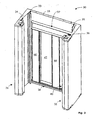
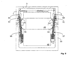
- Fig. 4 shows a top view of the hoistway, which may be peripherally terminated by another C-shaped structure or module 39 where an elevator car 40 is housed with doors 41, 42, 43, 44 forming a door system with sliding door leaves.
- the module 39 is designed statically non-supporting.
- a support 45 with rollers 93, 94, 95, 96 for guiding the elevator car is fixed at the top and bottom.
- four optionally preassembled shaft doors 46, 47, 48, 49 are shown, which can be mounted in the guides 37, 38.
- the balance weight guides 33 to 36 laterally, ie left and / or right to the at least approximately parallel or preferably an inner corner angle ⁇ > 90 ° forming sides 16, 17 (Fig. 1) of the C-shaped track element 30 and be arranged within the shaft wall projection.
- the module 39 may have a supporting function in the building, but without bearing the hoistway and its elements.
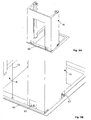
- FIGS. 5A and 5B Shown in FIGS. 5A and 5B is a roadway element 70 resting on a prefabricated well pit 60.
- This pit pit 60 is poured into the building floor panel of the building and is therefore later practically invisible from outside the elevator shaft.
- the tray 60 serves as a formwork during the casting of the building floor panel.
- a possible embodiment of a well pit 60 is shown in FIGS. 5A, 5B and 7 and represents a base module introduced by a builder as a pit.
- the tub 60 has a bottom 64.
- the term well may also be used to subsume a trough with a bottom having an opening or even a bottomless frame.
- the building floor slab is produced on a ground floor (e.g., the excavation floor), whereby the tub 60 can be poured.
- a first prefabricated delivered to the site for example, C-shaped roadway element 70 can be introduced, after which further roadway elements 20 (Fig. 2) are stacked and, with the building growing, mounted.
- This work can be carried out at least in part by a master builder.
- the stacked and supported on the building floor panel roadway elements form an elevator support structure, which can carry a top module (see, for example, Figures 8A and 8B) and stairwell pedestals.
- the roadway elements are preferably dimensioned from the statics forth so that they are able to absorb the vertical forces in the elevator shaft. In particular, these vertical rams are the own weight of the elevator shaft and the forces that occur during operation of the elevator.
- an installation example for the installation of a pit pit 60 is given.
- a pit a provided with a thin, horizontal mortar bed, taking into account the exact altitude.
- the pit tray 60 is inserted and pushed on this mortar bed in the correct position.
- the pit pit 60 can be filled with water so that it does not shift when pouring the building floor plate.
- Concrete is then poured into the excavation around the well pit to create the building floor slab.
- the first roadway element 70 is placed, as indicated schematically in Figures 6 and 7 by arrows.
- a thin layer of mortar can be applied.
- the roadway element 70 is positioned by means of a centering & positioning pin 71.
- the exact location in the horizontal plane is adjusted by rotation about a vertical axis 72.
- the roadway element is lowered into the mortar layer.
- the position of the roadway element can be adjusted.
- the mortar layer at least partially carries the weight of all roadway elements.
- the next following track element is preferably aligned after casting the first concrete deck (1st floor slab) with two centering & positioning bolts with respect to the underlying track element.
- the tray 60 has, as discussed, at least one integrated centering & positioning pin 71.
- the tray has screw holes 73 into which fixing screws 74 can be screwed to secure the track member 70 to the tray 60.
- the tub 60 an all-round Abdichtflansch 63 to seal from groundwater.
- the trough 60 may also be provided with tabs 75 which anchor the trough in the building floor panel. However, it does not have to be supportive of the elevator structure; the forces are preferably passed directly through the mortar layer in the building floor plate.
- Trained as a tray 60 base module has a low weight and a small volume for transport and installation and brings a drastic reduction in construction time and construction costs, in particular, no special hoist for larger loads is required.
- a basic module simultaneously fulfills building and elevator functions.
- the shaft pit had to be cast in concrete at the location of the lift shaft to be built by step by step, the corresponding shuttering made of wood were constructed. This process was very labor intensive and expensive. These steps are eliminated when using a trough 60 according to the invention.
- the trough 60 preferably consists of a CF composite.
- the tub 60 has a weight of less than 100kg.
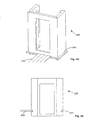
- the uppermost element of the elevator shaft which is also called top module 80, has at least one drive 81 and a plurality of rollers according to FIGS. 8A and 8B, for example the rollers 91, 92, 97, 98 for the cabin-side runners 82 and / or for the rollers counterweight strand 83 of the support and drive cables.
- the top module 80 to which the elevator car 40 and at least one counterweight (not shown here) hang indirectly (see FIG. 8B), may be a kind of cover 86 which extends from a flat roof 89 (building ceiling). is introduced ago.
- a drive 81 and pulleys 91, 92, 97, 98 are attached, and it has seals 87 against the building and at least one vent slot 88.
- the top module 80 preferably rests on an upper roadway element 100.
- the top module 80 is preferably a prefabricated concrete element.
- This top module 80 with integrated elevator and construction functions which is positioned and supported on the uppermost lane and door front module 100, may be factory pre-assembled with suspension and deflection rollers (eg, rollers 91, 92, 97, 98) with a factory pre-assembled one Drive unit 81 and / or be provided with integrated building interfaces or building interfaces for sealing and insulating the top building ceiling 89.
- the top module 80 can be used as an interior formwork for casting the building ceiling 89.
- top module 80 mounted on the shaft head and serving as a ceiling connection is cost-effective in terms of transport and assembly, affords great safety during elevator installation, can be used as packaging for the elevator components, for example the rollers and the drive, and also leads to minor on-site Costs of shaft head construction.
- the top module 80 may be configured such that it can be used as a weather protection during an installation phase.
- one roller 91 or 92 each is arranged for the two ropes 83 (FIG. 8B) carrying the counterweights 84 and 85, respectively, in such a way that the projection of each hanging one Rope 83 at least approximately through the center of gravity of the corresponding counterweight 84 and 85 runs.
- the four rollers 93, 94, 95, 96 are preferably formed by the trapezoidally shaped cabin guides 11, 12 (FIG. 1), or 21, 22 (FIG. 2), or 31, 33 (FIG. 3) of the respective modular one Track element led.
- the preferably C-shaped roadway elements 10 (FIG. 1), 20 (FIG. 2), 70 (FIG. 6) and 100 (FIG. 8B) can also be used to carry stairwell platforms, even if the complementary module 39 (FIG. Fig. 4 or Fig. 9) is omitted, for example, to form a respect to design and carrying forces free rear shaft wall area as a design freedom for architects.
- the C-shaped roadway elements 10, 20, 70 and 100 can then be "built in” and "outside” on the facade of a building, or built into a facade niche or attachable.
- the modular C-shaped roadway elements 10, 20, 70 and 100 according to the invention can be designed for direct reception of functional elements (eg functional elements of the door mechanism). It does not necessarily require special metal frames or metal profiles.
- the roadway elements 10, 20, 70 and 100 may have so-called gypsum edges to allow easier plastering of the shaft outer walls. Their modular design eliminates the need to compensate for building tolerances.
- the modular roadway elements 10, 20, 70 and 100 may have special recesses or attachment means have for direct, frameless fastening of the door mechanism.
- the modular elevator shaft according to the invention proves to be particularly advantageous in that no additional door frame is required for supporting or supporting doors, or for cleaning and accurate closure or for fire protection requirements.
- the individual modules or elements have only a low weight and a small volume, which not only brings advantages in transport and installation with it, but even allows the construction of the elevator shaft by the contractor construction company in the absence of elevator experts at the site without doing To require a specific lifting and lifting gear, because construction and elevator functions are met with the same elements or modules, even the display and controls may be pre-assembled.
- the rollers 93, 94, 95 and 96 are guided by the trapezoidal roadways 11 and 12 (FIG. 1), for example.
- the trapezoidal roadways 11 and 12 (FIG. 1) are preferably cast from concrete. Since these lanes serve only to guide the cabin 40, they are unproblematic from a static point of view. It is possible to provide relatively thin walls 16 and 17 ( Figure 1), which, however, should not be used for fastening or as supporting structures. Also, one should try in the design of the entire elevator shaft and the individual roadway elements to avoid sound bridges to allow good sound insulation.
- the horizontal Road loads due to eccentric loading of the elevator car 40 can reach relatively high levels. These horizontal loads are - even with thin walls 16 and 17 ( Figure 1) - unproblematic because they are collected on each floor by the floors.
- the connections between the roadway elements and the floor slabs can be realized either as rigid concrete / concrete joints or in the form of elastic sound insulation.
- the counterweight guide for example in the form of the rails 33 and 35, could also be arranged at least partially on the door front wall 3.
- the carrier 45 of the cab 40 ( Figure 9) is guided directly over the four upper guide rollers 93 to 95 and, for example, via four further lower rollers of a lower carrier not visible in the figures, for example along the concrete tracks 21, 22 ( Figure 2) ,
- the trapezoidal design of the roadways 21, 22 results in four elongated guide planes 24, 25 and 26, 27 in Fig. 2, which extend vertically in the elevator shaft.
- the intermediate levels 28 and 29 are not used to guide the elevator car 40, but may optionally be used for other functions. Due to the selected trapezoidal design of the roadways 21, 22, the guidance of the car 40 is very stable and also usable, for example, to absorb vertical forces.
- the guide geometry is very accurate, as the bump points and track distance are shaped.
- FIG. 10 The ends of a roadway 21, 22 (FIGS. 11, 12) of a roadway element are preferably provided with a coupling element 101 according to FIG. 10 cast directly in the concrete.
- Figures 11 and 12 show coupling pieces 110 and 120 at the ends of two abutting roadway elements. These coupling pieces 110 and 120 comprise a centering pin 121 (FIG. 12) and a centering hole 111 (FIG. 11), whereby they are automatically aligned with one another during assembly of the elevator shaft.
- the coupling pieces 101 are provided in the example shown with bolted anchors 131, 132 and 133, 134 of FIG. 13 and 14 to keep them anchored in the concrete after pouring.
- the surfaces 112, 113, 114 and 122, 123, 124 have the same polygonal cross-sectional shape, such as the trapezoidal lanes 11 and 12 of FIG. 1 or 21 and 22 of FIG. 2.
- the coupling pieces 110 and 120 are made of metal and can thus also serve as edge protection.
- the treads 11, 12, 21, 22 should have no grooves, heels or other bumps to bumps or
- rollers 93, 94, 95, 96 To avoid vibrations that could otherwise be transmitted via the rollers 93, 94, 95, 96 to the car 40.
- the coupling pieces 101 (FIG. 10), 110, 120 (FIGS. 11, 12) are inserted into the casting mold prior to the casting of the roadway elements. This results in ideally even transitions from the concrete cast guide treads to the coupling pieces. Since superimposed coupling pieces of adjacent roadway elements are mutually precisely centered, perfectly aligned, heel-free roadways result in the assembled state.
- the coupling pieces 101 preferably each have at least one recess 104 and / or a (threaded) bore 105, 106, which serve for the mutual fixation of two mutually-facing roadway elements, for example with connecting straps.
- (threaded) holes 107, 108 may be present with which a rotation or displacement of the inserted when casting the roadway elements in the mold coupling pieces is prevented.
- the roadway elements 10, 20, 30, 70 and 100 are preferably provided with a continuous cavity 19 and the coupling pieces 101 with openings 109 in order to be able to pass through such cavities 19 and openings 109, for example, at least one cable.
- the roadway elements 10, 20, 30, 70 and 100 are preferably provided with roadways 11, 12 and 21, 22 or 31, 32, which have an at least approximately trapezoidal cross section, wherein the coupling pieces 101 may be formed plate-shaped with the same trapezoidal cross-section.
- the sloping trapezoid sides of the carriageways may also serve as guides for rollers 93, 94, 95, 96 located on a support 45 fixed to the elevator car 40.
- the rollers 93, 94, 95, 96 may also be otherwise connected to the elevator car 40.
- FIG. 15 shows a modular roadway element 140, which has a type of circumferential ledge 141 in the lower region.
- This ledge 141 may, for example, support a formwork 142 for the casting of a floor slab, as illustrated in FIG.
- Another variant is shown in the sectional view in FIG. 16.
- the roadway element 150 has a recess 151 which can serve as a means for receiving a formwork 152, as indicated on the left side of the figure. Under certain circumstances, the means 141 and 151 can also carry the floor slab directly.
- the elevator shaft may be formed with prefabricated modular roadway elements (e.g., the roadway elements 10, 20) having an at least approximately C-shaped cross-section.
- a preferably modular elevator shaft may comprise roadways 11, 12 or 21, 22 or 31, 32, which have an at least approximately trapezoidal cross-section, wherein the sloping trapezoidal sides of the roadways as guide for rollers 93, 94, 95, 96, which are located on at least one support 45, which is attached to the elevator car 40.
- a modular elevator shaft can be formed with at least two prefabricated modular roadway elements (eg from the roadway elements 10, 20), which include roadways 11, 12, 21, 22 for the elevator car 40, such that at least at the upper end a lower lane of a lane element, a coupling piece 120 (FIG. 12) is fixedly arranged, and that at least at the lower end of an upper lane of a next lane element another coupling piece 110 (FIG. 11) is fixed, wherein both coupling pieces 110, 120 are configured in order to form an aligned transition between these two lanes at least in a region provided for guiding the elevator car 40.
- a coupling piece 120 FIG. 12
- both coupling pieces 110, 120 are configured in order to form an aligned transition between these two lanes at least in a region provided for guiding the elevator car 40.
- the elevator shaft can at least partially rest on a concrete floor slab in which a trough 60 is inserted, which serves as shuttering during the casting of the building floor slab.
- the shaft head of a hoistway can be designed as a modular prefabricated top module 80 made of concrete.
- elevators have been illustrated in which steel cords running over rollers carry the cab 40 and the counterweight (s).
- hydraulic drives can readily be used.
- straps can be used instead of ropes.
- inventive embodiments of such a hoistway prove to be particularly cost-effective in the production in the factory and for transport and installation. They provide increased safety during the lift assembly and possibly allow the use of a top module as a "packaging" of the elevator components, such as units with rollers and drive.
Abstract
Description
Die vorliegende Erfindung betrifft einen Aufzugsschacht nach dem Oberbegriff des Patentanspruchs 1 und ein Verfahren zur Errichtung eines Aufzugsschachts nach dem Oberbegriff des Patentanspruchs 13.The present invention relates to an elevator shaft according to the preamble of
Aus der Gebrauchsmusterschrift
Die Schachttürmodule können, falls unterschiedliche Stockwerkhöhen bestehen, eine Standard-Schachttüreinheit und eine auftragsspezifische Anpassungseinheit umfassen, die mittels auf dem Führungsschienenrahmen angebrachter Zapfen in vertikaler Achse zusemmengesteckt werden, um die vorgegebene Höhe des Schachttürmoduls zu erreichen. Für Reparaturen und Wartungen sind die Einbauten des Antriebsmoduls über eine Klappe vom Vorraum aus zugänglich. Bei einer Variante des Antriebmoduls sind die Treibscheiben mit je einem eigenen Antriebsaggregat versehen. Die hohlen Säulen der Schachttüreheinheit können aus verschiedenen Materialien, wie Stahl, Aluminium, Beton, Kunstoff bestehen und unterschiedliche Formen aufweisen.The landing door modules may, if different storey heights exist, comprise a standard hoistway door unit and an order-specific matching unit, which are clamped in a vertical axis by means of pins mounted on the guide rail frame to reach the predetermined height of the hoistway door module. For repairs and maintenance, the built-in components of the drive module are accessible from the vestibule via a flap. In a variant of the drive module, the traction sheaves are each provided with its own drive unit. The hollow pillars of the hoistway door unit may be made of various materials such as steel, aluminum, concrete, plastic and have different shapes.
Aus der Patentschrift CH 525 833 ist ferner eine Betonstruktur bekannt, die als Aufzugsschacht mit zwei Führungswänden, sowie einer vorderen Wand und einer Rückwand dient. An den Seitenwänden sind Rippen mit mehreren Führungsflächen ausgeführt, die als Führung für die Aufzugskabine dienen. Diese Rippen sind mit den Wandungsteilen homogen und kontinuierlich verbunden. Parallel zu diesen Rippen sind ähnliche Führungsteile vorhanden, um dem in Drähten oder Seilen geführten Gegengewicht aus Sicherheitsgründen eine zusätzliche Führung zu bieten. Die Seitenwände sind jeweils auf zwei gegenüberliegenden Enden, oben und unten, mit Zentrierungen versehen.From the patent CH 525 833 a concrete structure is also known, which serves as an elevator shaft with two guide walls, as well as a front wall and a rear wall. On the side walls ribs are designed with multiple guide surfaces, which serve as a guide for the elevator car. These ribs are homogeneously and continuously connected to the wall parts. Parallel to these ribs, similar guide members are provided to provide extra security to the wire or roped counterweight for safety reasons. The side walls are each provided on two opposite ends, top and bottom, with centerings.
Weiterhin ist aus der
Es ist nun Aufgabe der vorliegenden Erfindung, einen verbesserten Aufzugsschacht ähnlicher Gattung zu schaffen.It is an object of the present invention to provide an improved hoistway of a similar type.
Diese Aufgabe wird in vorteilhafter Weise erfindungsgemäss durch einen Aufzugsschacht nach Patentanspruch 1 und einem Verfahren nach Anspruch 13 gelöst.This object is achieved according to the invention by an elevator shaft according to
Durch die Erfindung lässt sich der Aufwand baulicher Art für derartige Systeme signifikant reduzieren.The invention makes it possible to significantly reduce the expense of a structural type for such systems.
Andere vorteilhafte Ausführungen der Erfindung ergeben sich aus den weiteren abhängigen Ansprüchen.Other advantageous embodiments of the invention will become apparent from the other dependent claims.
Die Erfindung wird nachfolgend, beispielsweise an Hand von Zeichnungen, näher erläutert. Es zeigen:
- Fig. 1 und 2
- schematische, perspektivische Darstellungen von zwei Fahrbahnelementen nach einer ersten Ausführung der Erfindung, die aufeinander montiert werden,
- Fig. 3
- eine perspektivische Darstellung einer zweiten Ausführung eines solchen Fahrbahnelements, das auch Fahrbahn- und Türfrontmodul genannt wird,
- Fig. 4
- eine schematische Querschnittdarstellung eines derartigen Fahrbahnelements,
- Fig. 5A
- eine schematische perspektivische Darstellung eines Fahrbahnelements, das auf einer in eine Gebäudebodenplatte eingegossenen Wanne ruht,
- Fig. 5B
- eine vergrösserte Detailansicht der Fig. 5A,
- Fig. 6
- eine perspektivische Darstellung eines Fahrbahnelements, bevor es auf eine in der Gebäudebodenplatte eingegossene Wanne nach der Erfindung abgesenkt wird,
- Fig. 7
- einige Details einer solchen Wanne,
- Fig. 8A
- eine schematische Seitenansicht eines Ausschnitts eines erfindungsgemässen Topmoduls,
- Fig. 8B
- eine schematische Seitenansicht des erfindungsgemässen Topmoduls nach Fig. 8A,
- Fig. 9
- eine schematische Querschnittdarstellung eines derartigen Topmoduls,
- Fig. 10
- eine Querschnittdarstellung eines Kopplungsstücks für erfindungsgemässe Fahrbahnelemente,
- Fig. 11 und 12
- eine perspektivische Darstellung von zwei aufeinander platzierbaren Fahrbahnelementen mit je einem Kopplungsstück an deren Enden,
- Fig. 13 und 14
- Detailansichten der Kopplungselemente vor dem Eingiessen,
- Fig. 15
- eine perspektivische Darstellung eines weiteren Fahrbahnelements, das Mittel zum Stützen einer Schalung aufweist, und
- Fig. 16
- eine schematische Schnittdarstellung eines weiteren Fahrbahnelements, das Mittel zum Stützen einer Schalung aufweist.
- Fig. 1 and 2
- schematic, perspective representations of two roadway elements according to a first embodiment of the invention, which are mounted on each other,
- Fig. 3
- a perspective view of a second embodiment of such a roadway element, which is also called roadway and door front module,
- Fig. 4
- a schematic cross-sectional view of such a roadway element,
- Fig. 5A
- a schematic perspective view of a roadway element, which rests on a cast in a building floor plate pan,
- Fig. 5B
- an enlarged detail view of FIG. 5A,
- Fig. 6
- a perspective view of a roadway element, before it is lowered onto a tray cast in the building floor panel according to the invention,
- Fig. 7
- some details of such a tub,
- Fig. 8A
- 1 is a schematic side view of a section of a top module according to the invention,
- Fig. 8B
- 1 is a schematic side view of the top module according to the invention according to FIG. 8A,
- Fig. 9
- a schematic cross-sectional view of such a top module,
- Fig. 10
- a cross-sectional view of a coupling piece for inventive roadway elements,
- FIGS. 11 and 12
- a perspective view of two successive placeable roadway elements, each with a coupling piece at the ends,
- FIGS. 13 and 14
- Detailed views of the coupling elements before pouring,
- Fig. 15
- a perspective view of another roadway element having means for supporting a formwork, and
- Fig. 16
- a schematic sectional view of another roadway element having means for supporting a formwork.
Die modularen Fahrbahnelemente 10 und 20 nach Fig. 1 und 2 weisen grundsätzlich drei Wände 1, 2, 3 und einen zumindest angenähert C-förmigen Querschnitt bzw. Grundriss auf. Diese C-förmigen Fahrbahnelemente 10 und 20 sind vorzugsweise derart aufgebaut, dass sie vorfabrizierte Fahrbahn- und Türfront-Module bilden, und umfassen je zwei integrierte Kabinenführungen oder Fahrbahnen 11, 12 (Fig. 1) bzw. 21, 22 (Fig. 2) und je eine Türöffnung 13 bzw. 23. In der Ausführung nach Fig. 1 sind die Ecken bzw. Eckkanten 14, 15 rechtwinklig ausgebildet, sie können jedoch auch abgerundet sein oder andere architektonisch und technisch sinnvolle Formen aufweisen. Sie müssen auch nicht unbedingt symmetrisch sein, wie in den Figuren 1 und 2 dargestellt.The
Die Flächen 16, 17 der Innenseiten des C-förmigen Fahrbahnelements können parallel sein oder, wie in Fig. 1 dargestellt, auf der Schachtinnenseite einen inneren Eckwinkel α bilden, der beispielsweise grϕsser als 90 Grad ist, wobei die Wände 1, 2 mit zunehmendem Abstand von der Wand 3 dünner werden können. Vorzugsweise sind die modularen Fahrbahnelemente 10 und 20 vorfabrizierte Betonmodule (z.B. aus gegossenem Beton), wobei die Fahrbahnelemente 10 und 20 mit Kanälen 18 oder anderen Ausnehmungen für eine integrierte Verkabelung versehen sein können. Die Fahrbahnen 11, 12 (Fig. 1) bzw. 21, 22 (Fig. 2) können mit einem durchgehenden Hohlraum 19, beispielsweise für ein Kabel zum gegenseitigen Verspannen mehrerer aufeinander ruhender Fahrbahnelemente 10, 20, versehen sein. Durch das gegenseitige Verspannen kann die Stabilität eines aus mehreren modularen Fahrbahnelementen 10, 20 bestehenden Aufzugsschachtes verbessert werden.The
Beton integrierte Führungen 33, 34 und 35, 36 für Ausgleichgewichte und im Beton integrierte Führungen 37, 38 für Schachttüren. Vorzugsweise sind diese Führungen direkt im Beton ausgeformt, oder zum Beispiel als Metallführungen in das Beton eingegossen.Concrete integrated guides 33, 34 and 35, 36 for balancing weights and guides integrated into the concrete 37, 38 for shaft doors. Preferably, these guides are formed directly in the concrete, or cast as metal guides in the concrete, for example.
Fig. 4 zeigt eine Draufsicht des Aufzugsschachts, der durch eine weitere C-förmige Konstruktion oder ein Modul 39 peripher abgeschlossen sein kann, wo eine Aufzugkabine 40 mit Türen 41, 42, 43, 44 untergebracht ist, die ein Türsystem mit verschiebbaren Türblättern bilden. Vorzugsweise ist das Modul 39 statisch nicht-tragend ausgeführt. An der Aufzugkabine 40 ist oben und unten je ein Träger 45 mit Rollen 93, 94, 95, 96 für die Führung der Aufzugkabine befestigt. In Fig. 3 sind auch vier gegebenenfalls vormontierbare Schachttüren 46, 47, 48, 49 dargestellt, die in den Führungen 37, 38 gelagert sein können. Zum seitlichen Platzgewinn können die Ausgleichgewichtsführungen 33 bis 36, wie in den Figuren 3 und 4 dargestellt, seitlich, das heisst links und/oder rechts an den zumindest angenähert parallelen oder vorzugsweise einen inneren Eckwinkel α > 90° bildenden Seiten 16, 17 (Fig. 1) des C-förmigen Fahrbahnelements 30 und innerhalb der Schachtwandprojektion angeordnet sein.Fig. 4 shows a top view of the hoistway, which may be peripherally terminated by another C-shaped structure or
In einer weiteren Ausführungsform kann das Modul 39 im Gebäude eine tragende Funktion haben, ohne jedoch den Aufzugschacht und dessen Elemente zu tragen.In a further embodiment, the
In Fig. 5A und Fig. 5B ist ein Fahrbahnelement 70 gezeigt, das auf einer vorgefertigten Schachtgrubenwanne 60 ruht.Shown in FIGS. 5A and 5B is a
Diese Schachtgrubenwanne 60 ist in die Gebäudebodenplatte des Gebäudes eingegossen und ist daher später von ausserhalb des Aufzugschachtes praktisch unsichtbar. Die Wanne 60 dient als Schalung beim Giessen der Gebäudebodenplatte. Eine mögliche Ausführungsform einer Schachtgrubenwanne 60 ist in Fig. 5A, Fig. 5B und Fig. 7 gezeigt und stellt ein durch einen Baumeister als Schachtgrube eingebrachtes Basismodul dar. Vorzugsweise weist die Wanne 60 einen Boden 64 auf. Unter dem Begriff Wanne kann im Sinne der Erfindung gegebenenfalls auch eine Wanne mit einem eine Öffnung aufweisenden Boden oder sogar ein bodenloser Rahmen subsumiert werden. Die Gebäudebodenplatte wird auf einem Grundboden (z.B. dem Baugrubenboden) hergestellt, wobei die Wanne 60 eingegossen werden kann. Dann kann darauf ein erstes vorfabriziertes auf die Baustelle geliefertes, beispielsweise C-förmig ausgebildetes Fahrbahnelement 70 eingebracht werden, wobei danach weitere Fahrbahnelemente 20 (Fig. 2) aufeinander geschichtet und, mit dem Gebäude wachsend, montiert werden. Diese Arbeiten können zumindest zum Teil durch einen Baumeister ausgeführt werden. Die aufeinander gestapelten und auf die Gebäudebodenplatte abgestützten Fahrbahnelemente bilden eine Aufzugstragstruktur, die ein Topmodul (siehe zum Beispiel Figuren 8A und 8B) und Treppenhauspodeste tragen kann. Vorzugsweise sind die Fahrbahnelemente von der Statik her so dimensioniert, dass sie die vertikalen Kräfte in dem Aufzugsschacht aufzunehmen in der Lage sind. Bei diesen vertikalen Kratten handelt es sich insbesondere um das Eigengewicht des Aufzugsschachtes und um die im Betrieb des Aufzugs auftretende Kräfte.This
Im Folgenden wird ein Montagebeispiel für die Montage einer Schachtgrubenwanne 60 angegeben. In einer Baugrube wird ein dünnes, waagerechtes Mörtelbeet bereitgestellt, wobei die genaue Höhenlage berücksichtigt werden muss. Die Schachtgrubenwanne 60 wird eingebracht und auf diesem Mörtelbeet in die korrekte Lage geschoben. Dann kann die Schachtgrubenwanne 60 mit Wasser gefüllt werden, damit sie sich beim Giessen der Gebäudebodenplatte nicht verschiebt. Anschliessend wird um die Schachtgrubenwanne herum Beton in die Baugrube gegossen, um die Gebäudebodenplatte zu erzeugen. Nach dem Aushärten der Gebäudebodenplatte wird das erste Fahrbahnelement 70 aufgesetzt, wie in den Figuren 6 und 7 schematisch durch Pfeile angedeutet. An der Auflagestelle des ersten Fahrbahnelements 70 auf der Schachtgrubenwanne 60 kann eine dünne Mörtelschicht aufgebracht werden. Das Fahrbahnelement 70 wird mittels eines Zentrier- & Positionierbolzens 71 positioniert. Die genaue Lage in der horizontalen Ebene wird mittels Rotation um eine vertikale Achse 72 justiert. Mit den Stellschrauben 62 wird das Fahrbahnelement in die Mörtelschicht abgesenkt. Durch Ein- oder Ausdrehen der Stellschrauben 62 kann die Lage des Fahrbahnelementes eingestellt werden. Es ist zu beachten, das die Mörtelschicht zumindest teilweise das Gewicht aller Fahrbahnelemente trägt. Das nächstfolgende Fahrbahnelement wird vorzugsweise nach dem Giessen der ersten Betondecke (1. Geschossdecke), mit zwei Zentrier- & Positionierbolzen in Bezug auf das darunter liegende Fahrbahnelement ausgerichtet.In the following, an installation example for the installation of a
Die Wanne 60 hat, wie besprochen, mindestens einen integrierten Zentrier- & Positionierbolzen 71. Zusätzlich weist die Wanne Schraubenlöcher 73 auf, in welche Fixierschrauben 74 eingeschraubt werden können, um das Fahrbahnelement 70 an der Wanne 60 zu befestigen. Vorzugsweise hat die Wanne 60 einen rundum laufenden Abdichtflansch 63, um von Grundwasser abzudichten. Die Wanne 60 kann auch mit Laschen 75 versehen sein, die die Wanne in der Gebäudebodenplatte verankern. Sie muss jedoch für die Aufzugsstruktur nicht tragend sein; die Kräfte werden vorzugsweise direkt über die Mörtelschicht in die Gebäudebodenplatte geleitet.The
Das als Wanne 60 ausgebildete Basismodul weist ein geringes Gewicht und ein kleines Volumen für Transport und Montage auf und bringt eine drastische Reduktion der Baudauer und der Baukosten mit sich, wobei insbesondere kein spezielles Hebezeug für grössere Lasten erforderlich ist. Zudem erfüllt ein solches Basismodul gleichzeitig Bau- und Aufzugsfunktionen. Bei herkömmlichen Aufzugsanlagen musste die Schachtgrubenwanne am Ort des zu errichtenden Aufzugsschachtes aus Beton gegossen werden, indem Schritt für Schritt die entsprechenden Verschalungen aus Holz aufgebaut wurden. Dieser Vorgang war sehr arbeitsintensiv und teuer. Diese Schritte entfallen bei Verwendung einer erfindungsgemässen Wanne 60. Vorzugsweise besteht die Wanne 60 aus einem CF-Composite. Die Wanne 60 hat beispielsweise ein Gewicht von weniger als 100kg.Trained as a
Das oberste Element des Aufzugschachts, das auch Topmodul 80 genannt wird, weist nach den Figuren 8A und 8B mindestens einen Antrieb 81 sowie mehrere Rollen auf, zum Beispiel die Rollen 91, 92, 97, 98 für die kabinenseitigen Trums 82 und/oder für die gegengewichtsseitigen Trums 83 der Trag- und Antriebsseile. Das Topmodul 80, an dem indirekt die Aufzugkabine 40 und mindestens ein - hier nicht dargestelltes - Gegengewicht hängen (siehe Fig. 8B), kann eine Art Deckel 86 sein, der von einem Flachdach 89 (Gebäudedecke) her eingebracht wird. An diesem Topmodul 80 sind ein Antrieb 81 sowie Umlenkrollen 91, 92, 97, 98 befestigt, und es weist Abdichtungen 87 gegenüber dem Gebäude und mindestens einen Lüftungsschlitz 88 auf. Wie der Fig. 8B zu entnehmen ist, sitzt das Topmodul 80 vorzugsweise auf einem oberen Fahrbahnelement 100 auf. Vorzugsweise handelt es sich bei dem Topmodul 80 um ein aus Beton vorgefertigtes Element.The uppermost element of the elevator shaft, which is also called
Dieses Topmodul 80 mit integrierten Aufzugs- und Baufunktionen, das auf das oberste Fahrbahn- und Türfrontmodul 100 positioniert und abgestützt wird, kann mit werksseitig vormontierten Aufhängungs- und Umlenkrollen (zum Beispiel die Rollen 91, 92, 97, 98), mit einer werksseitig vormontierten Antriebseinheit 81 und/oder mit integrierten Bauschnittstellen bzw. Gebäudeschnittstellen zum Dichten und Isolieren der obersten Gebäudedecke 89 versehen sein. Das Topmodul 80 kann als Innenverschalung für das Giessen der Gebäudedecke 89 verwendet werden.This
Ein solches am Schachtkopf montiertes und als Deckenanschluss dienendes Topmodul 80 ist kostengünstig, was den Transport und die Montage anbelangt, gewährt eine grosse Arbeitssicherheit während der Aufzugmontage, kann als Verpackung der Aufzugskomponenten, beispielsweise der Rollen und des Antriebs genutzt werden und führt zudem bauseits zu geringen Kosten beim Schachtkopfbau. Ausserdem kann das Topmodul 80 derart ausgestaltet sein, dass es als Wetterschutz während einer Einbauphase verwendbar ist.Such a
Nach Fig. 9 ist je eine Rolle 91 bzw. 92 für die zwei die Gegengewichte 84 bzw. 85 tragenden Seile 83 (Fig. 8B), derart angeordnet, dass die Projektion jedes hängenden Seiles 83 zumindest angenähert durch den Schwerpunkt des entsprechenden Gegengewichts 84 bzw. 85 verläuft. Es ist ein Träger 45 vorhanden, an dem vier Rollen 93, 94, 95, 96 drehbar angeordnet sind, die sich solidarisch mit der Aufzugkabine 40 bewegen. Die vier Rollen 93, 94, 95, 96 werden vorzugsweise durch die trapezförmig ausgebildete Kabinenführungen 11, 12 (Fig. 1), bzw. 21, 22 (Fig. 2), bzw. 31, 33 (Fig. 3) des jeweiligen modularen Fahrbahnelements geführt.According to FIG. 9, one
Die vorzugsweise C-förmig ausgebildeten Fahrbahnelemente 10 (Fig. 1), 20 (Fig. 2), 70 (Fig. 6) und 100 (Fig. 8B) können auch zum Tragen von Treppenhauspodeste genutzt werden, selbst wenn das komplementäre Modul 39 (Fig. 4 oder Fig. 9) entfällt, um beispielsweise einen bezüglich Design und Tragkräften freien hinteren Schachtwandbereich als Gestaltungsfreiraum für Architekten zu bilden. Die C-förmigen Fahrbahnelemente 10, 20, 70 und 100 können dann "innen" und "aussen" an die Fassade eines Gebäudes, oder in eine Fassadennische ein- oder anbaubar ausgebildet sein.The preferably C-shaped roadway elements 10 (FIG. 1), 20 (FIG. 2), 70 (FIG. 6) and 100 (FIG. 8B) can also be used to carry stairwell platforms, even if the complementary module 39 (FIG. Fig. 4 or Fig. 9) is omitted, for example, to form a respect to design and carrying forces free rear shaft wall area as a design freedom for architects. The C-shaped
Die modularen C-förmigen Fahrbahnelemente 10, 20, 70 und 100 gemäss Erfindung können zur direkten Aufnahme von Funktionselementen (z.B. Funktionselemente der Türmechanik) ausgeführt werden. Es bedarf dazu nicht unbedingt spezieller Metallrahmen oder Metallprofile. Die Fahrbahnelemente 10, 20, 70 und 100 können sogenannte Gipskanten aufweisen, um ein einfacheres Vergipsen der Schachtaussenwände zu ermöglichen. Durch ihre modulare Gestaltung entfällt ein Ausgleich von Bautoleranzen. Die modularen Fahrbahnelemente 10, 20, 70 und 100 können spezielle Ausnehmungen oder Befestigungsmittel zum direkten, rahmenlosen Befestigen der Türmechanik aufweisen.The modular C-shaped
Der erfindungsgemässe modular aufgebaute Aufzugsschacht erweist sich als besonders vorteilhaft dadurch, dass zum Tragen bzw. zum Abstützen von Türen, oder zum saubern und genauen Abschliessen oder für Brandschutzanforderungen kein zusätzlicher Türrahmen erforderlich ist. Die einzelnen Module oder Elemente weisen nur ein geringes Gewicht und ein kleines Volumen auf, was nicht nur Vorteile bei Transport und Montage mit sich bringt, sondern überhaupt die Errichtung des Aufzugsschachts durch die beauftragte Baufirma auch in Abwesenheit von Aufzugsexperten an der Baustelle ermöglicht, ohne dabei ein bezüglich Last und Hub spezielles Hebezeug benötigen zu müssen, weil Bau- und Aufzugsfunktionen mit denselben Elementen oder Modulen erfüllt werden, wobei sogar bereits die Anzeige- und Bedienungselemente vormontiert sein können.The modular elevator shaft according to the invention proves to be particularly advantageous in that no additional door frame is required for supporting or supporting doors, or for cleaning and accurate closure or for fire protection requirements. The individual modules or elements have only a low weight and a small volume, which not only brings advantages in transport and installation with it, but even allows the construction of the elevator shaft by the contractor construction company in the absence of elevator experts at the site without doing To require a specific lifting and lifting gear, because construction and elevator functions are met with the same elements or modules, even the display and controls may be pre-assembled.
Wie aus den Figuren 4 und 9 ersichtlich, werden beispielsweise die Rollen 93, 94, 95 und 96 durch die beispielsweise trapezförmig ausgebildeten Fahrbahnen 11 bzw. 12 (Fig. 1) geführt. Vorzugsweise sind die trapezförmig ausgebildeten Fahrbahnen 11 bzw. 12 (Fig. 1) aus Beton gegossen. Da diese Fahrbahnen lediglich zur Führung der Kabine 40 dienen, sind sie aus statischen Gesichtpunkten unproblematisch. Es ist möglich, relativ dünne Wände 16 und 17 (Fig. 1) vorzusehen, die aber dann nicht zum Befestigen oder als tragende Strukturen verwendet werden sollten. Auch sollte man bei der Konzeption des gesamten Aufzugschachtes und der einzelnen Fahrbahnelemente versuchen, Schallbrücken zu vermeiden, um eine gute Schallisolierung zu ermöglichen. Die horizontalen Fahrbahnbelastungen infolge von exzentrischer Beladung der Aufzugkabine 40 können relativ hohe Werte erreichen. Diese horizontalen Belastungen sind - auch bei dünnen Wänden 16 und 17 (Fig. 1) - unproblematisch, weil sie auf jedem Stockwerk durch die Geschossdecken aufgefangen werden. Die Verbindungen zwischen den Fahrbahnelementen und den Geschossdecken können entweder als starre Beton/Beton-Verbindungen oder in Form elastischer Schalldämmelemente realisiert werden.As can be seen in FIGS. 4 and 9, for example, the
Die Gegengewichtführung, zum Beispiel in Form der Schienen 33 und 35, könnte auch wenigstens zum Teil an der Türfrontwand 3 angeordnet sein.The counterweight guide, for example in the form of the
Der Träger 45 der Kabine 40 (Fig. 9) wird direkt über die vier oberen Führungsrollen 93 bis 95 und zum Beispiel über weitere vier in den Figuren nicht sichtbare untere Rollen eines unteren Trägers beispielsweise entlang den Betonfahrbahnen 21, 22 (Fig. 2) geführt.The
Durch die trapezförmige Gestaltung der Fahrbahnen 21, 22 ergeben sich vier längliche Führungsebenen 24, 25 bzw. 26, 27 in Fig. 2, die sich vertikal im Aufzugsschacht erstrekken. Die Zwischenebenen 28 bzw. 29 dienen nicht zum Führen der Aufzugkabine 40, sondern können gegebenenfalls für andere Funktionen benutzt werden. Durch die gewählte trapezförmige Bauform der Fahrbahnen 21, 22 ist die Führung der Kabine 40 sehr stabil und auch nutzbar, um zum Beispiel vertikale Kräfte aufzunehmen. Die Führungsgeometrie ist sehr genau, da Stoss-Stellen und Spurdistanz formgebunden sind.The trapezoidal design of the
Die Enden einer Fahrbahn 21, 22 (Fig. 11, 12) eines Fahrbahnelements sind vorzugsweise mit je einem direkt im Beton eingegossen Kopplungsstück 101 nach Fig. 10 versehen. Die Figuren 11 und 12 zeigen Kopplungsstücke 110 bzw. 120 an den Enden von zwei aneinander stossenden Fahrbahnelementen. Diese Kopplungsstücke 110 und 120 umfassen einen Zentrierbolzen 121 (Fig. 12) und eine Zentrierbohrung 111 (Fig. 11), wodurch sie bei der Montage des Aufzugschachtes selbsttätig gegeneinander ausgerichtet werden. Die Kopplungsstücke 101 sind in dem gezeigten Beispiel mit verschraubten Verankerungen 131, 132 und 133, 134 nach Fig. 13 und 14 versehen, um sie nach dem Eingiessen im Beton verankert zu halten. Die Flächen 112, 113, 114 bzw. 122, 123, 124 haben die gleiche polygonale Querschnittsform, wie beispielsweise die trapezförmigen Fahrbahnen 11 und 12 nach Fig. 1 oder 21 und 22 nach Fig. 2.The ends of a
Zum Herstellen der modularen Fahrbahnelemente 10, 20, 30 mit integrierten Fahrbahnen 21, 22 wird vorzugsweise eine Gussform verwendet. Idealerweise bestehen die Kopplungsstükke 110 bzw. 120 aus Metall und können somit auch als Kantenschutz dienen.For producing the
Die gegebenenfalls auch asymmetrisch im Querschnitt trapezförmig angeordneten Wände 24, 25 bzw. 26, 27 (Fig. 2), die den schräg stehenden Trapez-Seiten 102 und 103 in Fig. 10 entsprechen, schliessen beispielsweise einen Winkel von min. 60° und max. 120° ein, vorzugsweise jedoch einen Winkel von ca. 80° bis ca. 100°. Für den Winkel β in Fig. 10 gilt dementsprechend 60°> β > 30° oder vorzugsweise 50°> β > 40°. Die Laufflächen 11, 12, 21, 22 sollten keine Rillen, Absätze oder andere Unebenheiten aufweisen, um Stösse bzw.The optionally also asymmetrically in cross section trapezoidally arranged
Schwingungen zu vermeiden, die sich ansonsten über die Rollen 93, 94, 95, 96 auf die Kabine 40 übertragen könnten.To avoid vibrations that could otherwise be transmitted via the
Die Kopplungsstücke 101 (Fig. 10), 110, 120 (Fig. 11, 12) werden vor dem Giessen der Fahrbahnelemente in die Giessform eingelegt. Dadurch ergeben sich ideal ebene Übergänge von den aus Beton gegossenen Führungslaufflächen zu den Kopplungsstücken. Da aufeinander liegende Kopplungsstücke benachbarter Fahrbahnelemente gegenseitig präzise zentriert sind, resultieren im montierten Zustand perfekt fluchtende, absatzfreie Fahrbahnen.The coupling pieces 101 (FIG. 10), 110, 120 (FIGS. 11, 12) are inserted into the casting mold prior to the casting of the roadway elements. This results in ideally even transitions from the concrete cast guide treads to the coupling pieces. Since superimposed coupling pieces of adjacent roadway elements are mutually precisely centered, perfectly aligned, heel-free roadways result in the assembled state.
Die Kopplungsstücke 101 weisen vorzugsweise je mindestens eine Aussparung 104 und/oder eine (Gewinde-)Bohrung 105, 106 auf, die zur gegenseitigen Fixierung von zwei aufeinander stehenden Fahrbahnelementen, beispielsweise mit Verbindungslaschen, dienen. Ausserdem können darin (Gewinde-)Bohrungen 107, 108 vorhanden sein, mit welchen eine Verdrehung oder Verschiebung der beim Giessen der Fahrbahnelemente in die Giessform eingelegten Kopplungsstücke verhindert wird.
Die Fahrbahnelemente 10, 20, 30, 70 und 100 sind vorzugsweise mit einem durchgehenden Hohlraum 19 und die Kopplungsstücke 101 mit Öffnungen 109 versehen, um durch solche Hohlräume 19 und Öffnungen 109 zum Beispiel mindestens ein Kabel durchziehen zu können.The
The
Die Fahrbahnelemente 10, 20, 30, 70 und 100 sind vorzugsweise mit Fahrbahnen 11, 12 bzw. 21, 22 oder 31, 32 versehen, die einen zumindest angenähert trapezförmigen Querschnitt aufweisen, wobei die Kopplungsstücke 101 plattenförmig mit demselben trapezförmigen Querschnitt ausgebildet sein können. Die schräg stehenden Trapez-Seiten der Fahrbahnen können auch als Führung für Rollen 93, 94, 95, 96 dienen, die sich an einem Träger 45 befinden, der an der Aufzugskabine 40 befestigt ist. Die Rollen 93, 94, 95, 96 können aber auch anderweitig mit der Aufzugkabine 40 verbunden sein.The
Zwei weitere Ausführungsformen der Erfindung sind im Zusammenhang mit den Figuren 15 und 16 beschrieben. In Figur 15 ist ein modulares Fahrbahnelement 140 gezeigt, das im unteren Bereich eine Art umlaufenden Sims 141 aufweist. Dieser Sims 141 kann zum Beispiel eine Schalung 142 für das Giessen einer Geschossdecke abstützen, wie in Figur 15 ansatzweise dargestellt. Eine andere Variante ist in der Schnittdarstellung in Figur 16 gezeigt. Das Fahrbahnelement 150 weist eine Vertiefung 151 auf, die als Mittel zur Aufnahme einer Schalung 152 dienen kann, wie auf der linken Seite der Figur angedeutet. Die Mittel 141 und 151 können unter Umständen auch die Geschossdecke direkt tragen.Two further embodiments of the invention are described in connection with FIGS. 15 and 16. FIG. 15 shows a
Demzufolge kann nach einer ersten Ausführung der Erfindung der Aufzugsschacht mit vorfabrizierten modularen Fahrbahnelementen (z.B. aus den Fahrbahnelementen 10, 20) ausgebildet sein, die einen zumindest angenähert C-förmigen Querschnitt aufweisen.Accordingly, according to a first embodiment of the invention, the elevator shaft may be formed with prefabricated modular roadway elements (e.g., the
Nach einer zweiten Ausführung der Erfindung kann ein vorzugsweise modular aufgebauter Aufzugsschacht Fahrbahnen 11, 12 bzw. 21, 22 oder 31, 32 umfassen, die einen zumindest angenähert trapezförmigen Querschnitt aufweisen, wobei die schräg stehenden Trapez-Seiten der Fahrbahnen als Führung für Rollen 93, 94, 95, 96 dienen, die sich an mindestens einem Träger 45 befinden, der an der Aufzugskabine 40 befestigt ist.According to a second embodiment of the invention, a preferably modular elevator shaft may comprise
Nach einer dritten Ausführung kann ein modular aufgebauter Aufzugsschacht mit wenigstens zwei vorfabrizierten modularen Fahrbahnelementen (z.B. aus den Fahrbahnelementen 10, 20) ausgebildet sein, die Fahrbahnen 11, 12, 21, 22 für die Aufzugskabine 40 umfassen, derart, dass mindestens an dem oberen Ende einer unteren Fahrbahn eines Fahrbahnelements ein Kopplungsstück 120 (Fig. 12) fest angeordnet ist, und dass mindestens an dem unteren Ende einer oberen Fahrbahn eines nächsten Fahrbahnelements ein weiteres Kopplungsstück 110 (Fig. 11) fixiert ist, wobei beide Kopplungsstücke 110, 120 ausgestaltet sind, um wenigstens in einem für die Führung der Aufzugskabine 40 vorgesehenen Bereich einen fluchtenden Übergang zwischen diesen zwei Fahrbahnen zu bilden.According to a third embodiment, a modular elevator shaft can be formed with at least two prefabricated modular roadway elements (eg from the
Nach einer vierten Ausführung kann der Aufzugsschacht zumindest teilweise auf einer Gebäudebodenplatte aus Beton ruhen, in die eine Wanne 60 eingelassen ist, die als Schalung beim Giessen der Gebäudebodenplatte dient.According to a fourth embodiment, the elevator shaft can at least partially rest on a concrete floor slab in which a
Nach einer fünften Ausführung der Erfindung kann der Schachtkopf eines Aufzugsschachts als modulares vorfabriziertes Topmodul 80 aus Beton ausgebildet sein.According to a fifth embodiment of the invention, the shaft head of a hoistway can be designed as a modular prefabricated
Bei all diesen Ausführungen wurden Beispiele von Aufzügen dargestellt, bei denen über Rollen laufende Stahlseile die Kabine 40 und das(die) Gegengewicht(e) tragen. Bei diesen Ausführungsformen können jedoch ohne weiteres auch hydraulische Antriebe zum Einsatz gebracht werden. Statt Seilen können zum Beispiel auch Riemen eingesetzt werden.In all of these embodiments, examples of elevators have been illustrated in which steel cords running over rollers carry the
Die erfindungsgemässen Ausführungen eines solchen Aufzugsschachts erweisen sich als besonders kostengünstig bei der Herstellung im Werk sowie für Transport und Montage. Sie gewähren eine erhöhte Arbeitssicherheit während der Liftmontage und ermöglichen gegebenenfalls eine Benutzung eines Topmoduls als "Verpackung" der Aufzugskomponenten, beispielsweise der Einheiten mit Rollen und Antrieb.The inventive embodiments of such a hoistway prove to be particularly cost-effective in the production in the factory and for transport and installation. They provide increased safety during the lift assembly and possibly allow the use of a top module as a "packaging" of the elevator components, such as units with rollers and drive.
Claims (13)
- Lift shaft of modular construction comprising at least one prefabricated modular travel path element (10; 20; 30; 70; 100), which is formed by the two side walls (1, 2) and a third wall (3) arranged therebetween so that the travel path element (10; 20; 30; 70; 100) has an at least approximately C-shaped cross-section, and the two side walls (1, 2) each have an integrated travel path (11, 12; 21, 22) for guidance of the lift cage (40), characterised in that the travel path element (10; 20; 30; 70; 100) is of integral construction and that the third wall (3) is provided with a door opening (13; 23).
- Lift shaft according to claim 1, characterised in that the modular travel path element (10; 20; 30) is prefabricated integrally as a concrete structure and has cage guides (31, 32) integrated in the concrete structure and/or guides (33, 34; 35, 36), which are integrated in the concrete structure, for compensating weights and/or guides (37, 38), which are in the region of the door opening (13; 23) and integrated in the concrete structure, for shaft doors.
- Lift shaft according to claim 2, characterised in that not only the integrated cage guide (31, 32), but also the guides (33, 34; 35, 36) for the compensating weights are located at inner surfaces (16, 17) of the two side walls (1, 2) of the modular travel path element (10; 20; 30).
- Lift shaft according to one of claims 2 to 3, characterised in that the inner surfaces (16, 17) of the side walls (1, 2) of the modular travel path element (10; 20; 30) form at least in the region in which the guides (33, 34; 35, 36) for the compensating weights of the lift cage (40) are disposed form an inner corner angle (α) which is greater than 90 degrees and thus reduce the thickness of the side walls (1, 2) with increasing spacing from the third wall (3).
- Lift shaft according to one of claims 1 to 4, characterised in that the modular travel path element (10; 20; 30) is provided with channels (18), preferably for an integrated cabling, extending parallel to the cage guides.
- Lift shaft according to one of claims 1 to 5, characterised in that the lift shaft comprises several modular travel path elements (10; 20; 30) layered one on the other, wherein the modular travel path elements (10; 20; 30) are provided with a continuous cavity (19), preferably for a cable for prestressed connection of the modular travel path elements (10; 20; 30).
- Lift shaft according to one of claims 1 to 6, characterised in that the modular travel path element (10; 20; 30) is provided with travel paths (11, 12; 21, 22) which have an at least approximately trapezium-shaped cross-section and that the travel paths (11, 12; 21, 22) have obliquely disposed trapezium sides (24, 25, 26, 27) which serve as guide for rollers (93, 94, 95, 96) connected with the lift cage (40).
- Lift shaft according to one of claims 1 to 7, characterised in that the modular travel path element (10; 20; 30; 70; 100) is statically dimensioned in such a manner that it serves as a load-bearing structure in order to accept the vertical forces of the lift shaft, particularly the intrinsic weight of the lift shaft, and forces arising in operation of the lift.
- Lift shaft according to one of claims 1 to 8, characterised in that the modular travel path element (10; 20; 30; 70; 100) is dimensioned in such a manner that it can support a stairwell landing and/or a top module (80).
- Lift shaft according to one of claims 1 to 9, characterised in that a module (39) is mounted relative to the middle third wall (3) so as to close the lift shaft, wherein the module (39) is preferably constructed as a non-load-bearing element of the lift shaft.
- Lift shaft according to one of claims 1 to 10, characterised in that the modular travel path element (10; 20; 30) is equipped at the factory with integrated shaft doors (46, 47, 48, 49).
- Lift shaft according to one of claims 1 to 11, characterised in that at least one of the modular travel path elements (140; 150) comprises means (141; 151) suitable for supporting formwork for casting of a ceiling.
- Method of erecting a lift shaft according to one of claims 1 to 11, characterised in that a first prefabricated modular travel path element (10) is introduced onto a building floor plate, which is produced at the site of a building to be erected, the prefabricated modular travel path element (10) is aligned horizontally and vertically and thereafter at least one further modular travel path element (20) is positioned on the first prefabricated modular travel path element (10), wherein the lift shaft is assembled so as to grow with the building.
Priority Applications (1)
| Application Number | Priority Date | Filing Date | Title |
|---|---|---|---|
| EP02027351A EP1321417B1 (en) | 2001-12-21 | 2002-12-07 | Elevator shaft and method for erecting the elevator shaft |
Applications Claiming Priority (3)
| Application Number | Priority Date | Filing Date | Title |
|---|---|---|---|
| EP01811255 | 2001-12-21 | ||
| EP01811255 | 2001-12-21 | ||
| EP02027351A EP1321417B1 (en) | 2001-12-21 | 2002-12-07 | Elevator shaft and method for erecting the elevator shaft |
Publications (2)
| Publication Number | Publication Date |
|---|---|
| EP1321417A1 EP1321417A1 (en) | 2003-06-25 |
| EP1321417B1 true EP1321417B1 (en) | 2007-07-11 |
Family
ID=38289100
Family Applications (1)
| Application Number | Title | Priority Date | Filing Date |
|---|---|---|---|
| EP02027351A Expired - Lifetime EP1321417B1 (en) | 2001-12-21 | 2002-12-07 | Elevator shaft and method for erecting the elevator shaft |
Country Status (5)
| Country | Link |
|---|---|
| EP (1) | EP1321417B1 (en) |
| AT (1) | ATE366707T1 (en) |
| DE (1) | DE50210450D1 (en) |
| ES (1) | ES2290236T3 (en) |
| PT (1) | PT1321417E (en) |
Cited By (1)
| Publication number | Priority date | Publication date | Assignee | Title |
|---|---|---|---|---|
| CN109537849A (en) * | 2018-11-16 | 2019-03-29 | 立达博仕电梯(苏州)有限公司 | A kind of installation elevator shaft support frame |
Families Citing this family (6)
| Publication number | Priority date | Publication date | Assignee | Title |
|---|---|---|---|---|
| GB2473026A (en) * | 2009-08-26 | 2011-03-02 | Waycon Precast Ltd | Lift shaft assembly comprising pre-fabricated concrete sections |
| US8800725B2 (en) * | 2011-01-05 | 2014-08-12 | Dominick J. Alois | Elevator liner apparatus and utilization method thereof |
| CN114592708A (en) * | 2021-04-29 | 2022-06-07 | 深圳市凌盛电子有限公司 | Shielding-free anti-falling outer wall construction assembly in small high-rise building elevator reconstruction process |
| EP4083344A1 (en) * | 2021-04-30 | 2022-11-02 | Manfred Greschbach | Shaft element for an elevator facility and method for producing a shaft |
| CN115095106B (en) * | 2022-05-31 | 2024-01-30 | 上海宝冶集团有限公司 | Elevator shaft structure and construction method thereof |
| CN114922385A (en) * | 2022-07-18 | 2022-08-19 | 山东天齐置业集团股份有限公司 | Column type elevator guide rail fixing structure and construction method |
Family Cites Families (6)
| Publication number | Priority date | Publication date | Assignee | Title |
|---|---|---|---|---|
| CH525833A (en) * | 1969-11-11 | 1972-07-31 | Hladnik Damjan | Elevator shaft |
| DE2210631A1 (en) * | 1972-03-06 | 1973-09-20 | Haushahn Fa C | ELEVATOR FOR BUILDINGS |
| GB1459537A (en) * | 1974-11-21 | 1976-12-22 | Maquinaria Y Utiles Para La Co | Elevator |
| DE2755267A1 (en) * | 1977-12-12 | 1979-06-13 | Dieter Brodthage | Prefabricated lift shaft units - consist of assembled together slabs, lift structure components, guide rail members and shaft closure door |
| EP1086038A1 (en) * | 1998-06-10 | 2001-03-28 | Zünd AG | Elevator guiding device |
| DE20105144U1 (en) * | 2001-03-24 | 2001-07-12 | Mueller Wolfgang T | Self-supporting cable elevator with cabin and counterweight guide in the shaft door front |
-
2002
- 2002-12-07 EP EP02027351A patent/EP1321417B1/en not_active Expired - Lifetime
- 2002-12-07 ES ES02027351T patent/ES2290236T3/en not_active Expired - Lifetime
- 2002-12-07 AT AT02027351T patent/ATE366707T1/en not_active IP Right Cessation
- 2002-12-07 DE DE50210450T patent/DE50210450D1/en not_active Expired - Lifetime
- 2002-12-07 PT PT02027351T patent/PT1321417E/en unknown
Non-Patent Citations (1)
| Title |
|---|
| None * |
Cited By (2)
| Publication number | Priority date | Publication date | Assignee | Title |
|---|---|---|---|---|
| CN109537849A (en) * | 2018-11-16 | 2019-03-29 | 立达博仕电梯(苏州)有限公司 | A kind of installation elevator shaft support frame |
| CN109537849B (en) * | 2018-11-16 | 2020-10-20 | 立达博仕电梯(苏州)有限公司 | Install elevator well support frame additional |
Also Published As
| Publication number | Publication date |
|---|---|
| DE50210450D1 (en) | 2007-08-23 |
| PT1321417E (en) | 2007-09-12 |
| ATE366707T1 (en) | 2007-08-15 |
| ES2290236T3 (en) | 2008-02-16 |
| EP1321417A1 (en) | 2003-06-25 |
Similar Documents
| Publication | Publication Date | Title |
|---|---|---|
| EP2356056B1 (en) | Shaft frame for a lift system | |
| EP3899167B1 (en) | Construction site device with climbing formwork and elevator system | |
| EP3712355B1 (en) | Method for retrofitting a building with an elevator and set of components for carrying out the method | |
| EP1108828B1 (en) | Lift shaft | |
| EP3315448A2 (en) | Lift system | |
| EP1321417B1 (en) | Elevator shaft and method for erecting the elevator shaft | |
| EP1321418B1 (en) | Lift shaft | |
| DE3714053C2 (en) | Elevator for passenger transportation | |
| DE4316203A1 (en) | Railway station platform construction kit - comprises cross-beams fixed to concrete foundation and platform plates with integral beams fixed to cross-beams | |
| EP0350525B1 (en) | Method for producing building-walls and a shuttering system | |
| EP1736605B1 (en) | Balcony frame, balcony and manufacturing process for a prefabricated balcony | |
| EP1321419A1 (en) | Drive module for a modular lift shaft | |
| EP1321420A1 (en) | Shaft module for a lift | |
| EP1321421A1 (en) | Base frame which forms a base module for an elevator shaft | |
| EP1894876A1 (en) | Lift facility with cabin and counterweight and method for arranging a lift facility | |
| EP0606557B1 (en) | Railing to be fixed on side walls | |
| DE19814639A1 (en) | Lift installation for attachment to existing building of slab construction | |
| DE19954649C2 (en) | Method and device for retrofitting a prefabricated elevator shaft frame to a building | |
| DE10231775A1 (en) | Procedure for installing a passenger elevator | |
| DE1531102C3 (en) | Well equipment for an elevator | |
| EP1245759A1 (en) | Transportable workshop | |
| EP1707674A2 (en) | Railway platform with roof | |
| CH698874B1 (en) | Cable guide for a lift drive. | |
| DE102021117834A1 (en) | Elevating platform and method of installing or removing a dwelling unit in a main support structure of a building | |
| DE10212268A1 (en) | Modular-style lift with no machine chamber has integrated front with two columns extending from bottom to top of lift shaft either side of door opening and guiding at least one counter weight |
Legal Events
| Date | Code | Title | Description |
|---|---|---|---|
| PUAI | Public reference made under article 153(3) epc to a published international application that has entered the european phase |
Free format text: ORIGINAL CODE: 0009012 |
|
| AK | Designated contracting states |
Designated state(s): AT BE BG CH CY CZ DE DK EE ES FI FR GB GR IE IT LI LU MC NL PT SE SI SK TR |
|
| AX | Request for extension of the european patent |
Extension state: AL LT LV MK RO |
|
| 17P | Request for examination filed |
Effective date: 20031203 |
|
| AKX | Designation fees paid |
Designated state(s): AT BE BG CH CY CZ DE DK EE ES FI FR GB GR IE IT LI LU MC NL PT SE SI SK TR |
|
| 17Q | First examination report despatched |
Effective date: 20040906 |
|
| GRAP | Despatch of communication of intention to grant a patent |
Free format text: ORIGINAL CODE: EPIDOSNIGR1 |
|
| GRAS | Grant fee paid |
Free format text: ORIGINAL CODE: EPIDOSNIGR3 |
|
| GRAA | (expected) grant |
Free format text: ORIGINAL CODE: 0009210 |
|
| AK | Designated contracting states |
Kind code of ref document: B1 Designated state(s): AT BE BG CH CY CZ DE DK EE ES FI FR GB GR IE IT LI LU MC NL PT SE SI SK TR |
|
| REG | Reference to a national code |
Ref country code: GB Ref legal event code: FG4D Free format text: NOT ENGLISH |
|
| RIN1 | Information on inventor provided before grant (corrected) |
Inventor name: KOCHER, JOHANNES, MASCH. ING. HTL |
|
| REG | Reference to a national code |
Ref country code: CH Ref legal event code: EP |
|
| REF | Corresponds to: |
Ref document number: 50210450 Country of ref document: DE Date of ref document: 20070823 Kind code of ref document: P |
|
| REG | Reference to a national code |
Ref country code: IE Ref legal event code: FG4D Free format text: LANGUAGE OF EP DOCUMENT: GERMAN |
|
| GBT | Gb: translation of ep patent filed (gb section 77(6)(a)/1977) |
Effective date: 20070822 |
|
| REG | Reference to a national code |
Ref country code: PT Ref legal event code: SC4A Free format text: AVAILABILITY OF NATIONAL TRANSLATION Effective date: 20070830 |
|
| ET | Fr: translation filed | ||
| PG25 | Lapsed in a contracting state [announced via postgrant information from national office to epo] |
Ref country code: NL Free format text: LAPSE BECAUSE OF FAILURE TO SUBMIT A TRANSLATION OF THE DESCRIPTION OR TO PAY THE FEE WITHIN THE PRESCRIBED TIME-LIMIT Effective date: 20070711 Ref country code: BG Free format text: LAPSE BECAUSE OF FAILURE TO SUBMIT A TRANSLATION OF THE DESCRIPTION OR TO PAY THE FEE WITHIN THE PRESCRIBED TIME-LIMIT Effective date: 20071011 |
|
| NLV1 | Nl: lapsed or annulled due to failure to fulfill the requirements of art. 29p and 29m of the patents act | ||
| REG | Reference to a national code |
Ref country code: ES Ref legal event code: FG2A Ref document number: 2290236 Country of ref document: ES Kind code of ref document: T3 |
|
| REG | Reference to a national code |
Ref country code: IE Ref legal event code: FD4D |
|
| PG25 | Lapsed in a contracting state [announced via postgrant information from national office to epo] |
Ref country code: GR Free format text: LAPSE BECAUSE OF FAILURE TO SUBMIT A TRANSLATION OF THE DESCRIPTION OR TO PAY THE FEE WITHIN THE PRESCRIBED TIME-LIMIT Effective date: 20071012 Ref country code: DK Free format text: LAPSE BECAUSE OF FAILURE TO SUBMIT A TRANSLATION OF THE DESCRIPTION OR TO PAY THE FEE WITHIN THE PRESCRIBED TIME-LIMIT Effective date: 20070711 |
|
| PLBE | No opposition filed within time limit |
Free format text: ORIGINAL CODE: 0009261 |
|
| STAA | Information on the status of an ep patent application or granted ep patent |
Free format text: STATUS: NO OPPOSITION FILED WITHIN TIME LIMIT |
|
| PG25 | Lapsed in a contracting state [announced via postgrant information from national office to epo] |
Ref country code: IE Free format text: LAPSE BECAUSE OF FAILURE TO SUBMIT A TRANSLATION OF THE DESCRIPTION OR TO PAY THE FEE WITHIN THE PRESCRIBED TIME-LIMIT Effective date: 20070711 Ref country code: SK Free format text: LAPSE BECAUSE OF FAILURE TO SUBMIT A TRANSLATION OF THE DESCRIPTION OR TO PAY THE FEE WITHIN THE PRESCRIBED TIME-LIMIT Effective date: 20070711 Ref country code: CZ Free format text: LAPSE BECAUSE OF FAILURE TO SUBMIT A TRANSLATION OF THE DESCRIPTION OR TO PAY THE FEE WITHIN THE PRESCRIBED TIME-LIMIT Effective date: 20070711 |
|
| 26N | No opposition filed |
Effective date: 20080414 |
|
| BERE | Be: lapsed |
Owner name: INVENTIO A.G. Effective date: 20071231 |
|
| PG25 | Lapsed in a contracting state [announced via postgrant information from national office to epo] |
Ref country code: SE Free format text: LAPSE BECAUSE OF FAILURE TO SUBMIT A TRANSLATION OF THE DESCRIPTION OR TO PAY THE FEE WITHIN THE PRESCRIBED TIME-LIMIT Effective date: 20071011 |
|
| PG25 | Lapsed in a contracting state [announced via postgrant information from national office to epo] |
Ref country code: MC Free format text: LAPSE BECAUSE OF NON-PAYMENT OF DUE FEES Effective date: 20071231 |
|
| PG25 | Lapsed in a contracting state [announced via postgrant information from national office to epo] |
Ref country code: BE Free format text: LAPSE BECAUSE OF NON-PAYMENT OF DUE FEES Effective date: 20071231 |
|
| PG25 | Lapsed in a contracting state [announced via postgrant information from national office to epo] |
Ref country code: EE Free format text: LAPSE BECAUSE OF FAILURE TO SUBMIT A TRANSLATION OF THE DESCRIPTION OR TO PAY THE FEE WITHIN THE PRESCRIBED TIME-LIMIT Effective date: 20070711 |
|
| PG25 | Lapsed in a contracting state [announced via postgrant information from national office to epo] |
Ref country code: AT Free format text: LAPSE BECAUSE OF NON-PAYMENT OF DUE FEES Effective date: 20071207 |
|
| PG25 | Lapsed in a contracting state [announced via postgrant information from national office to epo] |
Ref country code: SI Free format text: LAPSE BECAUSE OF FAILURE TO SUBMIT A TRANSLATION OF THE DESCRIPTION OR TO PAY THE FEE WITHIN THE PRESCRIBED TIME-LIMIT Effective date: 20070711 |
|
| PGFP | Annual fee paid to national office [announced via postgrant information from national office to epo] |
Ref country code: CH Payment date: 20090317 Year of fee payment: 7 |
|
| PG25 | Lapsed in a contracting state [announced via postgrant information from national office to epo] |
Ref country code: CY Free format text: LAPSE BECAUSE OF FAILURE TO SUBMIT A TRANSLATION OF THE DESCRIPTION OR TO PAY THE FEE WITHIN THE PRESCRIBED TIME-LIMIT Effective date: 20070711 |
|
| PG25 | Lapsed in a contracting state [announced via postgrant information from national office to epo] |
Ref country code: LU Free format text: LAPSE BECAUSE OF NON-PAYMENT OF DUE FEES Effective date: 20071207 |
|
| PGFP | Annual fee paid to national office [announced via postgrant information from national office to epo] |
Ref country code: PT Payment date: 20091123 Year of fee payment: 8 |
|
| REG | Reference to a national code |
Ref country code: CH Ref legal event code: PL |
|
| PG25 | Lapsed in a contracting state [announced via postgrant information from national office to epo] |
Ref country code: LI Free format text: LAPSE BECAUSE OF NON-PAYMENT OF DUE FEES Effective date: 20091231 Ref country code: CH Free format text: LAPSE BECAUSE OF NON-PAYMENT OF DUE FEES Effective date: 20091231 |
|
| PGFP | Annual fee paid to national office [announced via postgrant information from national office to epo] |
Ref country code: TR Payment date: 20101122 Year of fee payment: 9 |
|
| REG | Reference to a national code |
Ref country code: PT Ref legal event code: MM4A Free format text: LAPSE DUE TO NON-PAYMENT OF FEES Effective date: 20110607 |
|
| PG25 | Lapsed in a contracting state [announced via postgrant information from national office to epo] |
Ref country code: PT Free format text: LAPSE BECAUSE OF NON-PAYMENT OF DUE FEES Effective date: 20110607 |
|
| PGFP | Annual fee paid to national office [announced via postgrant information from national office to epo] |
Ref country code: FI Payment date: 20111214 Year of fee payment: 10 Ref country code: ES Payment date: 20111227 Year of fee payment: 10 |
|
| PGFP | Annual fee paid to national office [announced via postgrant information from national office to epo] |
Ref country code: IT Payment date: 20111228 Year of fee payment: 10 |
|
| PG25 | Lapsed in a contracting state [announced via postgrant information from national office to epo] |
Ref country code: FI Free format text: LAPSE BECAUSE OF NON-PAYMENT OF DUE FEES Effective date: 20121207 |
|
| PG25 | Lapsed in a contracting state [announced via postgrant information from national office to epo] |
Ref country code: IT Free format text: LAPSE BECAUSE OF NON-PAYMENT OF DUE FEES Effective date: 20121207 |
|
| PG25 | Lapsed in a contracting state [announced via postgrant information from national office to epo] |
Ref country code: TR Free format text: LAPSE BECAUSE OF NON-PAYMENT OF DUE FEES Effective date: 20121207 |
|
| REG | Reference to a national code |
Ref country code: ES Ref legal event code: FD2A Effective date: 20140527 |
|
| PG25 | Lapsed in a contracting state [announced via postgrant information from national office to epo] |
Ref country code: ES Free format text: LAPSE BECAUSE OF NON-PAYMENT OF DUE FEES Effective date: 20121208 |
|
| REG | Reference to a national code |
Ref country code: FR Ref legal event code: PLFP Year of fee payment: 14 |
|
| REG | Reference to a national code |
Ref country code: FR Ref legal event code: PLFP Year of fee payment: 15 |
|
| REG | Reference to a national code |
Ref country code: FR Ref legal event code: PLFP Year of fee payment: 16 |
|
| PGFP | Annual fee paid to national office [announced via postgrant information from national office to epo] |
Ref country code: GB Payment date: 20211221 Year of fee payment: 20 Ref country code: FR Payment date: 20211227 Year of fee payment: 20 |
|
| PGFP | Annual fee paid to national office [announced via postgrant information from national office to epo] |
Ref country code: DE Payment date: 20211228 Year of fee payment: 20 |
|
| REG | Reference to a national code |
Ref country code: DE Ref legal event code: R071 Ref document number: 50210450 Country of ref document: DE |
|
| REG | Reference to a national code |
Ref country code: GB Ref legal event code: PE20 Expiry date: 20221206 |
|
| PG25 | Lapsed in a contracting state [announced via postgrant information from national office to epo] |
Ref country code: GB Free format text: LAPSE BECAUSE OF EXPIRATION OF PROTECTION Effective date: 20221206 |