EP1320465B1 - Method of manufacturing a run flat tire support and reinforcement - Google Patents
Method of manufacturing a run flat tire support and reinforcement Download PDFInfo
- Publication number
- EP1320465B1 EP1320465B1 EP01971398A EP01971398A EP1320465B1 EP 1320465 B1 EP1320465 B1 EP 1320465B1 EP 01971398 A EP01971398 A EP 01971398A EP 01971398 A EP01971398 A EP 01971398A EP 1320465 B1 EP1320465 B1 EP 1320465B1
- Authority
- EP
- European Patent Office
- Prior art keywords
- reinforcement
- rft
- filaments
- support
- mandrel
- Prior art date
- Legal status (The legal status is an assumption and is not a legal conclusion. Google has not performed a legal analysis and makes no representation as to the accuracy of the status listed.)
- Expired - Lifetime
Links
Images


Classifications
-
- B—PERFORMING OPERATIONS; TRANSPORTING
- B60—VEHICLES IN GENERAL
- B60C—VEHICLE TYRES; TYRE INFLATION; TYRE CHANGING; CONNECTING VALVES TO INFLATABLE ELASTIC BODIES IN GENERAL; DEVICES OR ARRANGEMENTS RELATED TO TYRES
- B60C15/00—Tyre beads, e.g. ply turn-up or overlap
- B60C15/02—Seating or securing beads on rims
- B60C15/0236—Asymmetric bead seats, e.g. different bead diameter or inclination angle
-
- B—PERFORMING OPERATIONS; TRANSPORTING
- B29—WORKING OF PLASTICS; WORKING OF SUBSTANCES IN A PLASTIC STATE IN GENERAL
- B29C—SHAPING OR JOINING OF PLASTICS; SHAPING OF MATERIAL IN A PLASTIC STATE, NOT OTHERWISE PROVIDED FOR; AFTER-TREATMENT OF THE SHAPED PRODUCTS, e.g. REPAIRING
- B29C39/00—Shaping by casting, i.e. introducing the moulding material into a mould or between confining surfaces without significant moulding pressure; Apparatus therefor
- B29C39/02—Shaping by casting, i.e. introducing the moulding material into a mould or between confining surfaces without significant moulding pressure; Apparatus therefor for making articles of definite length, i.e. discrete articles
- B29C39/028—Shaping by casting, i.e. introducing the moulding material into a mould or between confining surfaces without significant moulding pressure; Apparatus therefor for making articles of definite length, i.e. discrete articles having an axis of symmetry
-
- B—PERFORMING OPERATIONS; TRANSPORTING
- B29—WORKING OF PLASTICS; WORKING OF SUBSTANCES IN A PLASTIC STATE IN GENERAL
- B29C—SHAPING OR JOINING OF PLASTICS; SHAPING OF MATERIAL IN A PLASTIC STATE, NOT OTHERWISE PROVIDED FOR; AFTER-TREATMENT OF THE SHAPED PRODUCTS, e.g. REPAIRING
- B29C39/00—Shaping by casting, i.e. introducing the moulding material into a mould or between confining surfaces without significant moulding pressure; Apparatus therefor
- B29C39/02—Shaping by casting, i.e. introducing the moulding material into a mould or between confining surfaces without significant moulding pressure; Apparatus therefor for making articles of definite length, i.e. discrete articles
- B29C39/10—Shaping by casting, i.e. introducing the moulding material into a mould or between confining surfaces without significant moulding pressure; Apparatus therefor for making articles of definite length, i.e. discrete articles incorporating preformed parts or layers, e.g. casting around inserts or for coating articles
-
- B—PERFORMING OPERATIONS; TRANSPORTING
- B29—WORKING OF PLASTICS; WORKING OF SUBSTANCES IN A PLASTIC STATE IN GENERAL
- B29C—SHAPING OR JOINING OF PLASTICS; SHAPING OF MATERIAL IN A PLASTIC STATE, NOT OTHERWISE PROVIDED FOR; AFTER-TREATMENT OF THE SHAPED PRODUCTS, e.g. REPAIRING
- B29C41/00—Shaping by coating a mould, core or other substrate, i.e. by depositing material and stripping-off the shaped article; Apparatus therefor
- B29C41/02—Shaping by coating a mould, core or other substrate, i.e. by depositing material and stripping-off the shaped article; Apparatus therefor for making articles of definite length, i.e. discrete articles
- B29C41/04—Rotational or centrifugal casting, i.e. coating the inside of a mould by rotating the mould
- B29C41/042—Rotational or centrifugal casting, i.e. coating the inside of a mould by rotating the mould by rotating a mould around its axis of symmetry
- B29C41/045—Rotational or centrifugal casting, i.e. coating the inside of a mould by rotating the mould by rotating a mould around its axis of symmetry the axis being placed vertically, e.g. spin casting
-
- B—PERFORMING OPERATIONS; TRANSPORTING
- B29—WORKING OF PLASTICS; WORKING OF SUBSTANCES IN A PLASTIC STATE IN GENERAL
- B29C—SHAPING OR JOINING OF PLASTICS; SHAPING OF MATERIAL IN A PLASTIC STATE, NOT OTHERWISE PROVIDED FOR; AFTER-TREATMENT OF THE SHAPED PRODUCTS, e.g. REPAIRING
- B29C45/00—Injection moulding, i.e. forcing the required volume of moulding material through a nozzle into a closed mould; Apparatus therefor
- B29C45/0005—Injection moulding, i.e. forcing the required volume of moulding material through a nozzle into a closed mould; Apparatus therefor using fibre reinforcements
-
- B—PERFORMING OPERATIONS; TRANSPORTING
- B29—WORKING OF PLASTICS; WORKING OF SUBSTANCES IN A PLASTIC STATE IN GENERAL
- B29C—SHAPING OR JOINING OF PLASTICS; SHAPING OF MATERIAL IN A PLASTIC STATE, NOT OTHERWISE PROVIDED FOR; AFTER-TREATMENT OF THE SHAPED PRODUCTS, e.g. REPAIRING
- B29C48/00—Extrusion moulding, i.e. expressing the moulding material through a die or nozzle which imparts the desired form; Apparatus therefor
- B29C48/15—Extrusion moulding, i.e. expressing the moulding material through a die or nozzle which imparts the desired form; Apparatus therefor incorporating preformed parts or layers, e.g. extrusion moulding around inserts
- B29C48/151—Coating hollow articles
- B29C48/152—Coating hollow articles the inner surfaces thereof
- B29C48/153—Coating both inner and outer surfaces
-
- B—PERFORMING OPERATIONS; TRANSPORTING
- B29—WORKING OF PLASTICS; WORKING OF SUBSTANCES IN A PLASTIC STATE IN GENERAL
- B29C—SHAPING OR JOINING OF PLASTICS; SHAPING OF MATERIAL IN A PLASTIC STATE, NOT OTHERWISE PROVIDED FOR; AFTER-TREATMENT OF THE SHAPED PRODUCTS, e.g. REPAIRING
- B29C53/00—Shaping by bending, folding, twisting, straightening or flattening; Apparatus therefor
- B29C53/56—Winding and joining, e.g. winding spirally
- B29C53/58—Winding and joining, e.g. winding spirally helically
- B29C53/60—Winding and joining, e.g. winding spirally helically using internal forming surfaces, e.g. mandrels
-
- B—PERFORMING OPERATIONS; TRANSPORTING
- B60—VEHICLES IN GENERAL
- B60C—VEHICLE TYRES; TYRE INFLATION; TYRE CHANGING; CONNECTING VALVES TO INFLATABLE ELASTIC BODIES IN GENERAL; DEVICES OR ARRANGEMENTS RELATED TO TYRES
- B60C17/00—Tyres characterised by means enabling restricted operation in damaged or deflated condition; Accessories therefor
- B60C17/04—Tyres characterised by means enabling restricted operation in damaged or deflated condition; Accessories therefor utilising additional non-inflatable supports which become load-supporting in emergency
- B60C17/06—Tyres characterised by means enabling restricted operation in damaged or deflated condition; Accessories therefor utilising additional non-inflatable supports which become load-supporting in emergency resilient
- B60C17/061—Tyres characterised by means enabling restricted operation in damaged or deflated condition; Accessories therefor utilising additional non-inflatable supports which become load-supporting in emergency resilient comprising lateral openings
-
- B—PERFORMING OPERATIONS; TRANSPORTING
- B29—WORKING OF PLASTICS; WORKING OF SUBSTANCES IN A PLASTIC STATE IN GENERAL
- B29C—SHAPING OR JOINING OF PLASTICS; SHAPING OF MATERIAL IN A PLASTIC STATE, NOT OTHERWISE PROVIDED FOR; AFTER-TREATMENT OF THE SHAPED PRODUCTS, e.g. REPAIRING
- B29C2793/00—Shaping techniques involving a cutting or machining operation
- B29C2793/009—Shaping techniques involving a cutting or machining operation after shaping
-
- B—PERFORMING OPERATIONS; TRANSPORTING
- B29—WORKING OF PLASTICS; WORKING OF SUBSTANCES IN A PLASTIC STATE IN GENERAL
- B29C—SHAPING OR JOINING OF PLASTICS; SHAPING OF MATERIAL IN A PLASTIC STATE, NOT OTHERWISE PROVIDED FOR; AFTER-TREATMENT OF THE SHAPED PRODUCTS, e.g. REPAIRING
- B29C31/00—Handling, e.g. feeding of the material to be shaped, storage of plastics material before moulding; Automation, i.e. automated handling lines in plastics processing plants, e.g. using manipulators or robots
- B29C31/04—Feeding of the material to be moulded, e.g. into a mould cavity
-
- B—PERFORMING OPERATIONS; TRANSPORTING
- B29—WORKING OF PLASTICS; WORKING OF SUBSTANCES IN A PLASTIC STATE IN GENERAL
- B29C—SHAPING OR JOINING OF PLASTICS; SHAPING OF MATERIAL IN A PLASTIC STATE, NOT OTHERWISE PROVIDED FOR; AFTER-TREATMENT OF THE SHAPED PRODUCTS, e.g. REPAIRING
- B29C35/00—Heating, cooling or curing, e.g. crosslinking or vulcanising; Apparatus therefor
- B29C35/02—Heating or curing, e.g. crosslinking or vulcanizing during moulding, e.g. in a mould
-
- B—PERFORMING OPERATIONS; TRANSPORTING
- B29—WORKING OF PLASTICS; WORKING OF SUBSTANCES IN A PLASTIC STATE IN GENERAL
- B29C—SHAPING OR JOINING OF PLASTICS; SHAPING OF MATERIAL IN A PLASTIC STATE, NOT OTHERWISE PROVIDED FOR; AFTER-TREATMENT OF THE SHAPED PRODUCTS, e.g. REPAIRING
- B29C48/00—Extrusion moulding, i.e. expressing the moulding material through a die or nozzle which imparts the desired form; Apparatus therefor
- B29C48/03—Extrusion moulding, i.e. expressing the moulding material through a die or nozzle which imparts the desired form; Apparatus therefor characterised by the shape of the extruded material at extrusion
- B29C48/05—Filamentary, e.g. strands
-
- B—PERFORMING OPERATIONS; TRANSPORTING
- B29—WORKING OF PLASTICS; WORKING OF SUBSTANCES IN A PLASTIC STATE IN GENERAL
- B29C—SHAPING OR JOINING OF PLASTICS; SHAPING OF MATERIAL IN A PLASTIC STATE, NOT OTHERWISE PROVIDED FOR; AFTER-TREATMENT OF THE SHAPED PRODUCTS, e.g. REPAIRING
- B29C48/00—Extrusion moulding, i.e. expressing the moulding material through a die or nozzle which imparts the desired form; Apparatus therefor
- B29C48/03—Extrusion moulding, i.e. expressing the moulding material through a die or nozzle which imparts the desired form; Apparatus therefor characterised by the shape of the extruded material at extrusion
- B29C48/06—Rod-shaped
-
- B—PERFORMING OPERATIONS; TRANSPORTING
- B29—WORKING OF PLASTICS; WORKING OF SUBSTANCES IN A PLASTIC STATE IN GENERAL
- B29C—SHAPING OR JOINING OF PLASTICS; SHAPING OF MATERIAL IN A PLASTIC STATE, NOT OTHERWISE PROVIDED FOR; AFTER-TREATMENT OF THE SHAPED PRODUCTS, e.g. REPAIRING
- B29C48/00—Extrusion moulding, i.e. expressing the moulding material through a die or nozzle which imparts the desired form; Apparatus therefor
- B29C48/03—Extrusion moulding, i.e. expressing the moulding material through a die or nozzle which imparts the desired form; Apparatus therefor characterised by the shape of the extruded material at extrusion
- B29C48/07—Flat, e.g. panels
- B29C48/08—Flat, e.g. panels flexible, e.g. films
-
- B—PERFORMING OPERATIONS; TRANSPORTING
- B29—WORKING OF PLASTICS; WORKING OF SUBSTANCES IN A PLASTIC STATE IN GENERAL
- B29C—SHAPING OR JOINING OF PLASTICS; SHAPING OF MATERIAL IN A PLASTIC STATE, NOT OTHERWISE PROVIDED FOR; AFTER-TREATMENT OF THE SHAPED PRODUCTS, e.g. REPAIRING
- B29C48/00—Extrusion moulding, i.e. expressing the moulding material through a die or nozzle which imparts the desired form; Apparatus therefor
- B29C48/03—Extrusion moulding, i.e. expressing the moulding material through a die or nozzle which imparts the desired form; Apparatus therefor characterised by the shape of the extruded material at extrusion
- B29C48/12—Articles with an irregular circumference when viewed in cross-section, e.g. window profiles
-
- B—PERFORMING OPERATIONS; TRANSPORTING
- B29—WORKING OF PLASTICS; WORKING OF SUBSTANCES IN A PLASTIC STATE IN GENERAL
- B29C—SHAPING OR JOINING OF PLASTICS; SHAPING OF MATERIAL IN A PLASTIC STATE, NOT OTHERWISE PROVIDED FOR; AFTER-TREATMENT OF THE SHAPED PRODUCTS, e.g. REPAIRING
- B29C48/00—Extrusion moulding, i.e. expressing the moulding material through a die or nozzle which imparts the desired form; Apparatus therefor
- B29C48/15—Extrusion moulding, i.e. expressing the moulding material through a die or nozzle which imparts the desired form; Apparatus therefor incorporating preformed parts or layers, e.g. extrusion moulding around inserts
- B29C48/154—Coating solid articles, i.e. non-hollow articles
-
- B—PERFORMING OPERATIONS; TRANSPORTING
- B29—WORKING OF PLASTICS; WORKING OF SUBSTANCES IN A PLASTIC STATE IN GENERAL
- B29C—SHAPING OR JOINING OF PLASTICS; SHAPING OF MATERIAL IN A PLASTIC STATE, NOT OTHERWISE PROVIDED FOR; AFTER-TREATMENT OF THE SHAPED PRODUCTS, e.g. REPAIRING
- B29C48/00—Extrusion moulding, i.e. expressing the moulding material through a die or nozzle which imparts the desired form; Apparatus therefor
- B29C48/25—Component parts, details or accessories; Auxiliary operations
- B29C48/30—Extrusion nozzles or dies
- B29C48/32—Extrusion nozzles or dies with annular openings, e.g. for forming tubular articles
- B29C48/335—Multiple annular extrusion nozzles in coaxial arrangement, e.g. for making multi-layered tubular articles
-
- B—PERFORMING OPERATIONS; TRANSPORTING
- B29—WORKING OF PLASTICS; WORKING OF SUBSTANCES IN A PLASTIC STATE IN GENERAL
- B29C—SHAPING OR JOINING OF PLASTICS; SHAPING OF MATERIAL IN A PLASTIC STATE, NOT OTHERWISE PROVIDED FOR; AFTER-TREATMENT OF THE SHAPED PRODUCTS, e.g. REPAIRING
- B29C53/00—Shaping by bending, folding, twisting, straightening or flattening; Apparatus therefor
- B29C53/56—Winding and joining, e.g. winding spirally
- B29C53/58—Winding and joining, e.g. winding spirally helically
- B29C53/60—Winding and joining, e.g. winding spirally helically using internal forming surfaces, e.g. mandrels
- B29C53/62—Winding and joining, e.g. winding spirally helically using internal forming surfaces, e.g. mandrels rotatable about the winding axis
-
- B—PERFORMING OPERATIONS; TRANSPORTING
- B29—WORKING OF PLASTICS; WORKING OF SUBSTANCES IN A PLASTIC STATE IN GENERAL
- B29C—SHAPING OR JOINING OF PLASTICS; SHAPING OF MATERIAL IN A PLASTIC STATE, NOT OTHERWISE PROVIDED FOR; AFTER-TREATMENT OF THE SHAPED PRODUCTS, e.g. REPAIRING
- B29C53/00—Shaping by bending, folding, twisting, straightening or flattening; Apparatus therefor
- B29C53/80—Component parts, details or accessories; Auxiliary operations
- B29C53/8008—Component parts, details or accessories; Auxiliary operations specially adapted for winding and joining
- B29C53/805—Applying axial reinforcements
- B29C53/8058—Applying axial reinforcements continuously
-
- B—PERFORMING OPERATIONS; TRANSPORTING
- B29—WORKING OF PLASTICS; WORKING OF SUBSTANCES IN A PLASTIC STATE IN GENERAL
- B29C—SHAPING OR JOINING OF PLASTICS; SHAPING OF MATERIAL IN A PLASTIC STATE, NOT OTHERWISE PROVIDED FOR; AFTER-TREATMENT OF THE SHAPED PRODUCTS, e.g. REPAIRING
- B29C53/00—Shaping by bending, folding, twisting, straightening or flattening; Apparatus therefor
- B29C53/80—Component parts, details or accessories; Auxiliary operations
- B29C53/8008—Component parts, details or accessories; Auxiliary operations specially adapted for winding and joining
- B29C53/8066—Impregnating
- B29C53/8075—Impregnating on the forming surfaces
-
- B—PERFORMING OPERATIONS; TRANSPORTING
- B29—WORKING OF PLASTICS; WORKING OF SUBSTANCES IN A PLASTIC STATE IN GENERAL
- B29C—SHAPING OR JOINING OF PLASTICS; SHAPING OF MATERIAL IN A PLASTIC STATE, NOT OTHERWISE PROVIDED FOR; AFTER-TREATMENT OF THE SHAPED PRODUCTS, e.g. REPAIRING
- B29C67/00—Shaping techniques not covered by groups B29C39/00 - B29C65/00, B29C70/00 or B29C73/00
- B29C67/24—Shaping techniques not covered by groups B29C39/00 - B29C65/00, B29C70/00 or B29C73/00 characterised by the choice of material
- B29C67/246—Moulding high reactive monomers or prepolymers, e.g. by reaction injection moulding [RIM], liquid injection moulding [LIM]
-
- B—PERFORMING OPERATIONS; TRANSPORTING
- B29—WORKING OF PLASTICS; WORKING OF SUBSTANCES IN A PLASTIC STATE IN GENERAL
- B29K—INDEXING SCHEME ASSOCIATED WITH SUBCLASSES B29B, B29C OR B29D, RELATING TO MOULDING MATERIALS OR TO MATERIALS FOR MOULDS, REINFORCEMENTS, FILLERS OR PREFORMED PARTS, e.g. INSERTS
- B29K2025/00—Use of polymers of vinyl-aromatic compounds or derivatives thereof as moulding material
-
- B—PERFORMING OPERATIONS; TRANSPORTING
- B29—WORKING OF PLASTICS; WORKING OF SUBSTANCES IN A PLASTIC STATE IN GENERAL
- B29K—INDEXING SCHEME ASSOCIATED WITH SUBCLASSES B29B, B29C OR B29D, RELATING TO MOULDING MATERIALS OR TO MATERIALS FOR MOULDS, REINFORCEMENTS, FILLERS OR PREFORMED PARTS, e.g. INSERTS
- B29K2063/00—Use of EP, i.e. epoxy resins or derivatives thereof, as moulding material
-
- B—PERFORMING OPERATIONS; TRANSPORTING
- B29—WORKING OF PLASTICS; WORKING OF SUBSTANCES IN A PLASTIC STATE IN GENERAL
- B29K—INDEXING SCHEME ASSOCIATED WITH SUBCLASSES B29B, B29C OR B29D, RELATING TO MOULDING MATERIALS OR TO MATERIALS FOR MOULDS, REINFORCEMENTS, FILLERS OR PREFORMED PARTS, e.g. INSERTS
- B29K2075/00—Use of PU, i.e. polyureas or polyurethanes or derivatives thereof, as moulding material
-
- B—PERFORMING OPERATIONS; TRANSPORTING
- B29—WORKING OF PLASTICS; WORKING OF SUBSTANCES IN A PLASTIC STATE IN GENERAL
- B29K—INDEXING SCHEME ASSOCIATED WITH SUBCLASSES B29B, B29C OR B29D, RELATING TO MOULDING MATERIALS OR TO MATERIALS FOR MOULDS, REINFORCEMENTS, FILLERS OR PREFORMED PARTS, e.g. INSERTS
- B29K2105/00—Condition, form or state of moulded material or of the material to be shaped
- B29K2105/0005—Condition, form or state of moulded material or of the material to be shaped containing compounding ingredients
- B29K2105/0032—Pigments, colouring agents or opacifiyng agents
-
- B—PERFORMING OPERATIONS; TRANSPORTING
- B29—WORKING OF PLASTICS; WORKING OF SUBSTANCES IN A PLASTIC STATE IN GENERAL
- B29K—INDEXING SCHEME ASSOCIATED WITH SUBCLASSES B29B, B29C OR B29D, RELATING TO MOULDING MATERIALS OR TO MATERIALS FOR MOULDS, REINFORCEMENTS, FILLERS OR PREFORMED PARTS, e.g. INSERTS
- B29K2105/00—Condition, form or state of moulded material or of the material to be shaped
- B29K2105/04—Condition, form or state of moulded material or of the material to be shaped cellular or porous
-
- B—PERFORMING OPERATIONS; TRANSPORTING
- B29—WORKING OF PLASTICS; WORKING OF SUBSTANCES IN A PLASTIC STATE IN GENERAL
- B29K—INDEXING SCHEME ASSOCIATED WITH SUBCLASSES B29B, B29C OR B29D, RELATING TO MOULDING MATERIALS OR TO MATERIALS FOR MOULDS, REINFORCEMENTS, FILLERS OR PREFORMED PARTS, e.g. INSERTS
- B29K2105/00—Condition, form or state of moulded material or of the material to be shaped
- B29K2105/06—Condition, form or state of moulded material or of the material to be shaped containing reinforcements, fillers or inserts
- B29K2105/08—Condition, form or state of moulded material or of the material to be shaped containing reinforcements, fillers or inserts of continuous length, e.g. cords, rovings, mats, fabrics, strands or yarns
-
- B—PERFORMING OPERATIONS; TRANSPORTING
- B29—WORKING OF PLASTICS; WORKING OF SUBSTANCES IN A PLASTIC STATE IN GENERAL
- B29K—INDEXING SCHEME ASSOCIATED WITH SUBCLASSES B29B, B29C OR B29D, RELATING TO MOULDING MATERIALS OR TO MATERIALS FOR MOULDS, REINFORCEMENTS, FILLERS OR PREFORMED PARTS, e.g. INSERTS
- B29K2267/00—Use of polyesters or derivatives thereof as reinforcement
-
- B—PERFORMING OPERATIONS; TRANSPORTING
- B29—WORKING OF PLASTICS; WORKING OF SUBSTANCES IN A PLASTIC STATE IN GENERAL
- B29K—INDEXING SCHEME ASSOCIATED WITH SUBCLASSES B29B, B29C OR B29D, RELATING TO MOULDING MATERIALS OR TO MATERIALS FOR MOULDS, REINFORCEMENTS, FILLERS OR PREFORMED PARTS, e.g. INSERTS
- B29K2309/00—Use of inorganic materials not provided for in groups B29K2303/00 - B29K2307/00, as reinforcement
- B29K2309/08—Glass
-
- B—PERFORMING OPERATIONS; TRANSPORTING
- B29—WORKING OF PLASTICS; WORKING OF SUBSTANCES IN A PLASTIC STATE IN GENERAL
- B29K—INDEXING SCHEME ASSOCIATED WITH SUBCLASSES B29B, B29C OR B29D, RELATING TO MOULDING MATERIALS OR TO MATERIALS FOR MOULDS, REINFORCEMENTS, FILLERS OR PREFORMED PARTS, e.g. INSERTS
- B29K2995/00—Properties of moulding materials, reinforcements, fillers, preformed parts or moulds
- B29K2995/0018—Properties of moulding materials, reinforcements, fillers, preformed parts or moulds having particular optical properties, e.g. fluorescent or phosphorescent
- B29K2995/002—Coloured
-
- B—PERFORMING OPERATIONS; TRANSPORTING
- B29—WORKING OF PLASTICS; WORKING OF SUBSTANCES IN A PLASTIC STATE IN GENERAL
- B29L—INDEXING SCHEME ASSOCIATED WITH SUBCLASS B29C, RELATING TO PARTICULAR ARTICLES
- B29L2009/00—Layered products
-
- B—PERFORMING OPERATIONS; TRANSPORTING
- B29—WORKING OF PLASTICS; WORKING OF SUBSTANCES IN A PLASTIC STATE IN GENERAL
- B29L—INDEXING SCHEME ASSOCIATED WITH SUBCLASS B29C, RELATING TO PARTICULAR ARTICLES
- B29L2030/00—Pneumatic or solid tyres or parts thereof
-
- B—PERFORMING OPERATIONS; TRANSPORTING
- B60—VEHICLES IN GENERAL
- B60C—VEHICLE TYRES; TYRE INFLATION; TYRE CHANGING; CONNECTING VALVES TO INFLATABLE ELASTIC BODIES IN GENERAL; DEVICES OR ARRANGEMENTS RELATED TO TYRES
- B60C17/00—Tyres characterised by means enabling restricted operation in damaged or deflated condition; Accessories therefor
- B60C17/04—Tyres characterised by means enabling restricted operation in damaged or deflated condition; Accessories therefor utilising additional non-inflatable supports which become load-supporting in emergency
- B60C17/06—Tyres characterised by means enabling restricted operation in damaged or deflated condition; Accessories therefor utilising additional non-inflatable supports which become load-supporting in emergency resilient
- B60C2017/063—Tyres characterised by means enabling restricted operation in damaged or deflated condition; Accessories therefor utilising additional non-inflatable supports which become load-supporting in emergency resilient comprising circumferentially extending reinforcements
-
- B—PERFORMING OPERATIONS; TRANSPORTING
- B60—VEHICLES IN GENERAL
- B60C—VEHICLE TYRES; TYRE INFLATION; TYRE CHANGING; CONNECTING VALVES TO INFLATABLE ELASTIC BODIES IN GENERAL; DEVICES OR ARRANGEMENTS RELATED TO TYRES
- B60C17/00—Tyres characterised by means enabling restricted operation in damaged or deflated condition; Accessories therefor
- B60C17/04—Tyres characterised by means enabling restricted operation in damaged or deflated condition; Accessories therefor utilising additional non-inflatable supports which become load-supporting in emergency
- B60C17/06—Tyres characterised by means enabling restricted operation in damaged or deflated condition; Accessories therefor utilising additional non-inflatable supports which become load-supporting in emergency resilient
- B60C2017/068—Tyres characterised by means enabling restricted operation in damaged or deflated condition; Accessories therefor utilising additional non-inflatable supports which become load-supporting in emergency resilient comprising springs, e.g. helical springs
-
- Y—GENERAL TAGGING OF NEW TECHNOLOGICAL DEVELOPMENTS; GENERAL TAGGING OF CROSS-SECTIONAL TECHNOLOGIES SPANNING OVER SEVERAL SECTIONS OF THE IPC; TECHNICAL SUBJECTS COVERED BY FORMER USPC CROSS-REFERENCE ART COLLECTIONS [XRACs] AND DIGESTS
- Y10—TECHNICAL SUBJECTS COVERED BY FORMER USPC
- Y10T—TECHNICAL SUBJECTS COVERED BY FORMER US CLASSIFICATION
- Y10T152/00—Resilient tires and wheels
- Y10T152/10—Tires, resilient
- Y10T152/10036—Cushion and pneumatic combined
- Y10T152/10054—Enclosed cushion
-
- Y—GENERAL TAGGING OF NEW TECHNOLOGICAL DEVELOPMENTS; GENERAL TAGGING OF CROSS-SECTIONAL TECHNOLOGIES SPANNING OVER SEVERAL SECTIONS OF THE IPC; TECHNICAL SUBJECTS COVERED BY FORMER USPC CROSS-REFERENCE ART COLLECTIONS [XRACs] AND DIGESTS
- Y10—TECHNICAL SUBJECTS COVERED BY FORMER USPC
- Y10T—TECHNICAL SUBJECTS COVERED BY FORMER US CLASSIFICATION
- Y10T152/00—Resilient tires and wheels
- Y10T152/10—Tires, resilient
- Y10T152/10495—Pneumatic tire or inner tube
- Y10T152/10738—Pneumatic tire or inner tube with means to protect tire from rim
-
- Y—GENERAL TAGGING OF NEW TECHNOLOGICAL DEVELOPMENTS; GENERAL TAGGING OF CROSS-SECTIONAL TECHNOLOGIES SPANNING OVER SEVERAL SECTIONS OF THE IPC; TECHNICAL SUBJECTS COVERED BY FORMER USPC CROSS-REFERENCE ART COLLECTIONS [XRACs] AND DIGESTS
- Y10—TECHNICAL SUBJECTS COVERED BY FORMER USPC
- Y10T—TECHNICAL SUBJECTS COVERED BY FORMER US CLASSIFICATION
- Y10T428/00—Stock material or miscellaneous articles
- Y10T428/24—Structurally defined web or sheet [e.g., overall dimension, etc.]
- Y10T428/24058—Structurally defined web or sheet [e.g., overall dimension, etc.] including grain, strips, or filamentary elements in respective layers or components in angular relation
- Y10T428/24074—Strand or strand-portions
- Y10T428/24091—Strand or strand-portions with additional layer[s]
Definitions
- the field of invention relates to pneumatic tires.
- the invention particularly relates to run flat tire supports for pneumatic tires.
- an RFT wheel assembly includes a rim, a tire mounted on the rim, and a support sandwiched between an inner surface of the tire and an outer peripheral surface of a rim.
- the support allows the tire to deflect a limited amount so that the tire does not separate from the rim along each edge of the tire.
- a synthetic material such as a polymer, is typically used for the support.
- a challenge in manufacturing the support is to provide adequate structural integrity to have sufficient strength, so that outwardly directed centrifugal forces do not substantially deform the RFT support during rotational use. Further, the support needs to be able to support the weight of the vehicle on the tire, when the tire contacts the support as the tire rolls. The structural integrity is balanced with structural flexibility, in that the support is typically deformed slightly to insert the support into the tire prior to mounting the tire to the rim.
- a mold for the support can include a narrow channel of about three millimeters (mm) in width that is formed about an inner or outer periphery of the mold.
- the polymer support can be reinforced to help maintain its structural integrity during adverse conditions by providing a reinforcement in the molding process. The reinforcement is placed in the channel prior to molding and the polymer typically flows therethrough to encapsulate the reinforcement into the molded RFT support.
- a mesh of reinforcement material typically known as a woven "scrim” cloth
- the number of layers is at least partially determined by an amount of reinforcement resistance to deflection desired, as an indication of strength, with more layers providing more strength when other parameters are constant.
- the scrim cloth reinforcement in multiple layers, is then "stuffed” into the mold channel and the polymer flowed into the mold.
- Material especially fibrous material
- multiple layers of scrim cloth or other reinforcement material can add difficulties in inserting the multiple layers into the mold, if the layers are decoupled from each other or become delaminated during use.
- the present invention provides a method of making unitary run flat tire (RFT) support reinforcement that is formed from a filament material into a relatively rigid shape.
- the unitary RFT support reinforcement can be formed from multiple layers that are coupled together, such as with an adhesive, to form one effective layer.
- the one effective layer can include layers of filaments wound into a reinforcement.
- the reinforcement is insertable into a mold for an RFT support and can maintain the needed structural rigidity for such insertion.
- the RFT reinforcement can have a rigidity sufficient to deform about 20% or less when dropped from about two meters high to a hard surface when an axis of the RFT reinforcement is substantially perpendicular to gravity.
- the invention provides a method of manufacturing RFT support that is molded and includes the RFT reinforcement.
- the RFT support may be used to produce a wheel assembly including a tire, a rim, and an RFT support between the rim and the tire, where the support includes the RFT reinforcement.
- the RFT support can have a colored indicator formed or subsequently applied thereto to indicate one or more attributes of the support.
- the method of manufacturing an RFT support comprises placing at least one RFT reinforcement into a portion of an RFT support mold, the reinforcement being formed from one or more filaments and being unitary and having a rigidity sufficient to deform about 20% or less when dropped from about two meters high to a hard surface when an axis of the RFT reinforcement is substantially perpendicular to gravity; injecting a moldable elastomer or elastomer-forming material into the mold; flowing the moldable material through at least a portion of the reinforcement; and allowing the moldable material to at least partially solidify to form the RFT support.
- a method of manufacturing an RFT reinforcement comprising forming one or more filaments around a mandrel; coupling at least one portion of the one or more filaments to another portion of the filaments to form a tubular member; and optionally cutting the tubular member into cylindrical sections; thereby forming at least one unitary RFT reinforcement having one effective layer.
- the present invention generally includes a run flat tire (RFT) reinforcement, an RFT support including the RFT reinforcement, and a wheel assembly including the RFT support, tire, and rim. Further, the invention includes methods of manufacturing the RFT support and reinforcement.
- RFT run flat tire
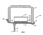
- FIG. 1 is a schematic partial cross sectional view of a wheel assembly.
- a wheel assembly 10 includes a rim 12, a tire 14 mounted on the rim, and an RFT support 16 mounted between an inner peripheral surface of the tire and an outer peripheral surface of the rim.
- the rim 12 can include a center support 24 which allows attachment of the wheel assembly 10 to a vehicle (not shown).
- the center support 24 can generally can be a web, spokes, or other attachment element, and can include a separate multi-piece element, as is known in the commercial trucking industry for wheel assemblies.
- the rim 12 also includes a first rim flange 26 and a second rim flange 28.
- the outer diameter of the RFT support 16 is generally the same or greater than the inner diameter of the tire 14 at the beads 30 and 32.
- the RFT support 16 is generally compressed circumferentially in at least one direction to an elliptical shape so that the RFT support can be inserted within the tire 14 generally prior to insertion of the RFT support onto the rim 12.
- the support 16 should be relatively rigid to support a load of the tire in an underinflated condition, but is also sufficiently flexible to allow changing the shape for installation.
- the materials for the RFT support are discussed in reference to Figure 2.
- the RFT support 16 includes an outer hoop 18, and inner hoop 20, and a center web 19 disposed therebetween. Further, the RFT support 16 includes at least one RFT reinforcement 22 molded therein. The RFT support can have a colored indicator on one or more of the RFT support surfaces as described more fully in reference to Figures 11-12.
- FIG 2 is a perspective schematic view of an RFT support 16, shown in Figure 1.
- the RFT support 16 includes in one embodiment an outer hoop 18 generally having a tire support surface 15 for the tire 14 that is shown in Figure 1, an inner hoop 20 generally having a rim support surface 21 for the rim 12 that is also shown in Figure 1, and a center web 19 disposed therebetween.
- At least one RFT reinforcement 22 is molded into the RFT support.
- the RFT reinforcement is molded into the inner hoop 20, although the reinforcement could be molded in other areas of the support, including the outer hoop 18 and the center web 19.
- multiple RFT reinforcements can be molded at more than one position in the RFT support.
- multiple RFT reinforcements could be molded at either different diametrical spacings or different lateral spacings, such as side-by-side, in the RFT support.
- the RFT reinforcement is formed into a unitary member, in that, the reinforcement is a substantially continuous member, such as a cylinder, having one effective layer prior to inserting the reinforcement in a mold for molding.
- the RFT reinforcement is formed from a plurality of elements or layers, then generally the elements or layers are coupled together through mechanical attachment, chemical attachment, such as with coatings that would include binders, adhesives, and other substances that cause adherence between at least two elements or layers, or other methods that would join such portions together to form one effective layer.
- the reinforcement does not need coupling around the entire periphery to be considered having "one effective layer" for the purposes of this invention.
- the reinforcement is coupled together sufficiently, so that it can be held together without substantial delamination, as described herein.
- the reinforcement can be coupled around at least the majority of its periphery.
- the coupling of the multiple layers together should be sufficient to remain intact during customary handling procedures of a manufacturing process, so that the layers do not delaminate. Delamination can cause delays in a manufacturing process during insertion of the reinforced member into the RFT support mold.
- the loft of the material used in the RFT reinforcement can be reduced in some embodiments, especially when a coating is used to reduce the thickness of the material and/or to retain fibers to adjacent fibers.
- the thinner material can assist in placement in a mold.
- the reinforcement 22 assists in resisting crack propagation in the RFT support and otherwise contributes to the structural integrity of the support 16, particularly when the support 16 is mounted on the rim 12, shown in Figure 1, and placed in use.
- the center web 19 can include openings 40 to achieve weight reduction and material savings.
- the openings 40 can be any geometric shape and generally are round, elliptical, square, triangular, rectangular, parallelogram, rhombus, or diamond shaped.
- the center web 19 can be made of a flexible material to allow flexing of the support for installation in the wheel assembly 10, described in reference to Figure 1.
- the support 16 can be formed through molding and one embodiment is formed through reaction injection molding (RIM), a technique known to those with ordinary skill in the art.
- RIM can also include, without limitation, variations such as structural reaction injection molding (SRIM) and reinforced reaction injection molding (RRIM).
- Other methods can include resin transfer molding (RTM), thermoplastic injection molding, blow molding, rotational molding, foam molding, bead foam molding, compression molding, profile extrusion, and spin casting. These various techniques are known in the industry for producing molded parts.
- the material for the RFT support can be any moldable material.
- Suitable materials for use in preparing these RFT supports include, for example, the classes of thermoplastic elastomers commercially available according to the "Handbook of Thermoplastic Elastomers," 2nd Edition, edited by B.M. Walker and Charles P. Rader, Van Nostrand Reinhold, New York, 1988. These are: styrenic block copolymers; rubber-polyolefin blends; elastomeric alloys; thermoplastic polyurethanes; thermoplastic copolyesters; and thermoplastic polyamides. Under the category of elastomeric alloys, there are thermoplastic vulcanizates (TPVs) and melt processable rubbers (MPRs).
- TPVs thermoplastic vulcanizates
- MPRs melt processable rubbers
- Other useful materials can include polyvinyl chloride; polyethylene copolymers (including ethylene/styrene copolymers via constrained geometry catalysis); hydrogenated styrene block copolymers; polylactic acid polymers; and ethylene/carbon monoxide copolymers.
- thermosetting or vulcanizable elastomers commercially available according to "Rubber Technology," 3rd Edition, edited by M. Morton, Kluwer Academic Publishers, Boston, 1999 which can be used to prepare the RFT supports.
- These elastomers include natural rubber (cis-1,4-polyisoprene); styrene-butadiene rubbers; polybutadiene rubbers; polyisoprene rubbers; ethylenepropylene rubbers, polychloroprene polymers; chlorinated polyethylene; chlorosulfonated polyethylene; silicone rubbers; flurocarbon elastomers; polyurethane elastomers; polysulfide elastomers; hydrogenated nitrile rubbers; propylene oxide polymers (vulcanizable copolymers of PO and allyl glycidyl ether); epichlorohydrin polymers; and ethylene acrylic elastomers (ethylene/ methyl acrylate/ carboxy
- polycoprolactam/polyether copolymers such as NYRIM®.
- Curing can be accomplished through self-cure, catalytically induced cure, thermal cure, photo sensitive cure, free radically initiated cure, actinic cure, such as X-ray cure, electron beam cure, microwave cure, and other cures known to those of ordinary skill in the art.
- exemplary polyurethanes suitable for the RFT support can include at least one polyol, at least one chain extender, and at least one isocyanate.
- Such polyurethanes include those materials cited and prepared in accordance the disclosure in PCT application WO 01/42000, by The Dow Chemical Company of Midland, Michigan, USA, the assignee of the present invention.
- PCT publication WO 01/42000 describes polyurethane-polymer compositions that are useful for making a lightweight tire support.
- Example 1 of this PCT publication describes one composition that can be particularly useful, although other materials can be used.
- a polyurethane-polymer composition was prepared by admixing a polyol-side stream and an isocyanate-side stream using reaction injection molding.
- the polyol-side stream included a polyol formulation.
- the polyol formulation included a polyol in an amount of 54.81 weight percent, a chain extender in an amount of 44.84 weight percent, a surfactant in an amount of 0.25 weight percent, and a catalyst in an amount of 0.1 weight percent.
- the polyol was an ethylene-oxide capped 5,000 molecular-weight triol having a maximum unsaturation of 0.035 milliequivalents per gram of the total composition (available from The Dow Chemical Company, Freeport, Texas).
- the chain extender was diethyl toluene diamine (a mixture of 3,5-diethyl-2,4- and 2,6'-toluene diamines) (available from The Dow Chemical Company, Freeport, Texas).
- the surfactant was a silicone surfactant (L-1000; available from OSI Specialties/Witco Corp., Chicago, Illinois).
- the catalyst included a 50:50 combination of triethylene diamine (Dabco 3LV) (available from Air Products and Chemicals, Inc., Allentown, Pennsylvania) and dibutyl tin dilaurate (Fomrez UL28) (available from Witco Chemical Co., Chicago, Illinois.)
- the isocyanate-side stream included a prepolymer formulation.
- the prepolymer formulation included a first isocyanate in an amount of 31.83 weight percent, a polyol in an amount of 63.17 weight percent, and a second isocyanate in an amount of 5.0 weight percent.
- the first isocyanate was 98 percent pure p,p'-MDI (Isonate 125M) (available from The Dow Chemical Company, Freeport, Texas).
- the polyol was an ethylene-oxide capped (15 percent) 6,000 molecular-weight triol with a maximum unsaturation of 0.02 milliequivalent per gram of total composition (available from Asahi).
- the second isocyanate was 50 percent p,p'-MDI and 50 percent o,p-MDI (Isonate 50 OP) (available from The Dow Chemical Company, Freeport, Texas).
- the isocyanate-side stream and the polyol-side stream were combined in a weight-ratio blend of 2:15:1 (isocyanate to polyol) using standard reaction-injection-molding processing conditions.
- the formulation in this example can vary for the purposes of the present invention. For example, testing conditions, tolerances in formulation of raw materials, and variances with processing can alter the composition within acceptable ranges. Further, the formulation can be modified to alter properties of the tire support, such as but not limited to, altering the ratio of chain extender and polyol, eliminating a second isocyanate, and using polyols that are not ethylene-oxide capped. Still further, the ranges given in the PCT publication WO 01/42000 can also produce other suitable formulations.
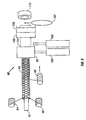
- FIG 3 is a schematic side view of another embodiment of the RFT support.
- the RFT support 16 in the embodiment shown in Figure 3 includes a set of components that can be molded in separate operations.
- the RFT support 16 includes an outer hoop 18, a center web 19, and an inner hoop 20, which in at least one embodiment includes an RFT reinforcement 22.
- the hoops and/or web can be formed from one or more thermoplastic foams, such as elastomer bead foams.
- the hoops and/or web can be unfoamed.
- the inner hoop 20 can be formed of a dynamic thermoplastic foam.
- the density can be controlled to provide a relatively rigid inner hoop.
- the RFT reinforcement 22 can be formed of a fibrous or other suitable material and, in at least one embodiment, is coupled to the inner hoop by being affixed or molded therein.
- the center web 19 can be formed of a lower density dynamic thermoplastic foam.
- the center web 19 can optionally contain load bearing optimized openings (not shown) for weight reduction.
- the outer hoop 18 can be a higher density dynamic thermoplastic foam.
- the combination can provide sufficient strength to the inner surfaces, such as the inner hoop 20, and still be sufficient to allow the shape to change as needed for installation of the RFT support into the tire 14 and onto the rim 12, as shown in Figure 1.
- the hoops and/or web can be molded using a conventional molding, such as foam or bead foam molding techniques known to those with ordinary skill in the art.
- a portion of the inner hoop 20 can be formed and an RFT reinforcement 22 placed around the portion to form the inner hoop.
- the inner hoop 20 can optionally be prepared using a profile extrusion system.
- the inner hoop 20 could be reinforced by the RFT reinforcement 22 molded therein.
- the center web 19 can be molded around the inner hoop 20 and the RFT reinforcement 22.
- the outer hoop 18 can be molded around the center web 19.
- the RFT reinforcement 22 can be disposed in other positions in the RFT support 16.
- the RFT reinforcement can be disposed or otherwise formed in or adjacent to the outer hoop 18 or the center web 19.
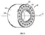
- FIG 4 is a schematic view of an exemplary rigid, unitary RFT reinforcement.
- the RFT reinforcement 22 generally includes at least one transverse member 42.
- a second transverse member 42a intercepts the transverse member 42.
- the reinforcement 22 can include at least one substantially circumferential member 44.
- the transverse members 42, 42a can be wound symmetrically, that is, at similar angles with respect to a center axis 23. Transverse angles ⁇ 1 , ⁇ 2 can be used to describe the angle of the transverse members 42, 42a, respectively, relative to the center axis 23.
- the transverse angles can be more than about 0 degrees to less than about 90 degrees, and advantageously about 70 degrees to about 80 degrees, such as about 78 degrees.
- One exemplary spacing 43 between adjacent transverse members can be about 20 mm to about 30 mm, such as about 24 mm.
- the transverse members can be a variety of widths and in at least one embodiment can be between about 2 mm to about 5 mm, such as about 3 mm.
- the circumferential members 44 can be a width generally of about 2 mm to about 10 mm, such as between about 5 mm to about 8 mm.
- the circumferential members can be equally or non-equally spaced across a width of the RFT reinforcement of about 70 mm to about 120 mm, such as about 90 mm.
- a circumferential angle ⁇ can be used to describe the angle of the circumferential member(s) and generally is a large angle, that is, almost perpendicular to the axis 23, although any angle between about 0 degrees and about 90 degrees can be used.
- the angle ⁇ can be between about 80 degrees to about 90 degrees.
- transverse members and circumferential members can be formed for different filaments or from a common filament, as described below regarding Figure 6.
- the RFT reinforcement of the present invention advantageously has a higher rigidity than found in prior efforts.
- the higher rigidity allows the reinforcement to be manually or automatically handled and to be placed relatively quickly in position in an RFT support mold.
- the speed and efficiency improves the productivity of an RFT support which should, in turn, allow for the economic production of the mass quantities of supports required for the transportation market.
- a prior art RFT reinforcement comprising multiple layers of a scrim cloth took about 45 seconds to place in an RFT support mold in one comparative test.
- some tests using at least one embodiment of the RFT reinforcement disclosed herein took about 10-15 seconds or less to place in the mold, that is, less than one-third of the time using the prior art.
- the tests showed that it was possible to reduce the time to about 2-5 seconds or less and generally about 3 seconds or less, that is, about an order of magnitude difference in time from the prior art.
- the RFT reinforcement can also contain openings 46 formed therethrough.
- the openings allow liquid reactants to penetrate the reinforcement during the molding process of the RFT support, so that the reinforcement becomes an integral part of the RFT support when the liquid reactants solidify.
- the reinforcement is substantially encapsulated by the polymer.
- the RFT reinforcement can be made from a variety of moldable and metallic materials.
- the transverse members and/or circumferential members can be made of fiberglass, carbon/graphite fibers, aramid fibers, polyester fibers, metal fibers and other materials.
- the types of fibers can be combined into composites to include combinations of glass, carbon/graphite, aramid, polyester, metal and other materials.
- the material can include metallic cloth materials, such as wire mesh, or solid rings.
- the fibers can additionally include a binder, sizing, dressing, or other coating to facilitate processing, binding or heat sealing of the fibers.
- the individual fibers can be formed into filaments or tape.
- the fibers can be cut into discrete layers to produce cut fibers and can be included in a moldable material.
- the term "filament” is used broadly and includes ribbons, fibers, tapes, yarn, tow, roving, and other individual, or groups of, materials to be wound about the mandrel.
- the term "mandrel” includes a member around which the filaments or other material are wound or formed. The mandrel can be reused for subsequent winding or forming, or can be integrated into the RFT reinforcement and/or RFT support in the processing of the same, for example, by cutting the member as a portion of the RFT support or RFT reinforcement.
- a collapsible mandrel can be used to advantage to facilitate the removal of the RFT reinforcement.
- the reinforcement can include thin strands of wire woven into the material. Further, the reinforcement can be made from sheets, and in some embodiments laminated sheets.
- the RFT reinforcement can also be made of reinforced thermoplastic containing fibers.
- the fiber composition of the thermoplastic can range from about 20% to about 99%, although other percentages are possible.
- the RFT reinforcement comprises a weight per square meter of about 50 grams to about 1000 grams per square meter.
- the reinforcement be sufficiently rigid to allow relatively quick and easy insertion into the mold and still be sufficiently flexible to allow compression of the RFT support for installation of the RFT support into the wheel assembly, shown in Figure 1. Further, the reinforcement can be sufficiently rigid to help provide structural resistance to the otherwise outward expansion of the molded support during rotation and the accompanying outward centrifugal forces, such that the support substantially maintains its structural integrity during its intended use. For purposes herein, such stiffness will be referred to as "hoop stiffness,” that is, the ability to resist an outward expansion due to rotating radial forces.
- the fibers can have a coating applied through spraying, dipping, encapsulating, extruding, impregnating, combining with films, or other methods known to those in the art that are available before or after the fibers are formed into an appropriate shape for the RFT reinforcement to produce a self-supporting structure that is capable of not collapsing when the structure is without external supports.
- the reinforcement material could be dipped in a coagulation dip coating prior to forming around a mandrel and a relatively rigid polymer could be applied to act as an aqueous dispersant to provide suitable the self-supporting structure.
- the reinforcement preferably advantageously has a balanced weight distribution around the reinforcement periphery to assist the centrifugal balance of the final RFT support during driving conditions.
- the RFT reinforcement can be made in individual units or can be made as a tubular member and one or more reinforcement units cut from the tubular member.
- the RFT reinforcement can be filament wound about a mandrel.
- the RFT reinforcement can be made from prepared cloth or sheets that are rolled into a desired shape and the ends or other portions of the material coupled to each other.
- the term "coupled,” “coupling,” and like terms as used herein includes adhering, bonding, binding, curing, fastening, attaching, and other forms of securing one piece to another piece.
- FIG. 5A is a schematic prospective view of another embodiment of the RFT reinforcement 22, which does not correspond to the present invention.
- the RFT reinforcement 22 includes a relatively solid member that can be perforated with openings 46.
- opening and like terms are used broadly and include any aperture formed in the support and/or reinforcement, such as holes, slots, and other apertures.
- perforate and like terms are used broadly and include any method for forming openings in a material, such as molding, drilling, stamping, punching, melting, and other aperture forming methods.
- Openings 46 allow the molding material to flow therethrough.
- the openings allow the molding material to flow through and around the reinforcement 22, so that the reinforcement 22 is at least partially encapsulated, and preferably substantially encapsulated, by the molding material. It is to be understood that the openings are optional and other embodiments may not have substantial openings.
- the RFT reinforcement can be made from a relatively thin tube of material and processed by punching, drilling, cutting or otherwise forming openings 46.
- the material can be metal, composites, fiber reinforced composites, plastics, or other material that can be shaped into an essentially circular form.
- the terms "circular” and “cylindrical” are used broadly and include any shape forming a loop without hard corners, such as circles, ellipses and irregularly shaped geometric figures.
- Figure 5B is a partial schematic cross-sectional view of an opening 46 formed in the RFT reinforcement shown in Figure 5A.
- a surface 48 of the RFT reinforcement 22 has been perforated.
- the surface 48 can be perforated, so that a tab 50 is disposed adjacent surface 48 to form the opening 46.
- the tab 50 can be useful in increasing a coupling force to subsequent molded material of the inner hoop 20 that surrounds the reinforcement, shown in Figures 1 and 2.
- the tab can also be useful is locating the reinforcement in a mold.
- the tab can extend in any direction, including toward the center of the reinforcement.
- the opening 46 can be formed without producing a tab 50.
- One property indicating suitable rigidity of the RFT reinforcement 22 is by measuring the deformation in a drop test.
- a test regimen for the reinforcements was to form a cylindrical reinforcement and determine the average diameter of the reinforcement from side to side when the reinforcement was lying horizontally in a state of rest.
- the reinforcement was rotated vertically, that is, the axis 23 that is shown in Figure 4, was substantially perpendicular to gravity and elevated, so that a lower portion of reinforcement was at a height of about two meters above an uncushioned concrete floor.
- Other hard surfaces could also be used, such as wood, metal, or relatively rigid polymer surfaces.
- the reinforcement was dropped to test the amount of deformation occurring after the drop when the reinforcement was again lying horizontally in a state of rest.
- the resulting shape was elliptical rather than circular.
- the dimensions of the resulting ellipse were measured after recovery when the reinforcement was again horizontal in a state of rest.
- the resulting dimension from side to side of the reinforcement after the drop generally decreased in a direction of the drop or increased in a corresponding amount in a direction perpendicular to the drop.
- a difference between either the decreased amount in one direction or the increased amount in the other direction compared to the original average diameter was used to calculate an average deformation percentage.
- the reinforcement was then reshaped into a circle prior to the next test. The test was repeated several times. Additionally, any delamination was noted as would cause the RFT reinforcement to be difficult to insert into a mold.
- the deflection percentage was about 20% or less, then the reinforcement generally had a rigidity that allowed the reinforcement to be inserted relatively easily into the support mold. Naturally, the deflection percentage could be more and still be usable. An advantageous percentage was about 10% or less, a more advantageous percentage was about 5% or less, and an even more advantageous percentage was about 1% or less.
- the reinforcement can be produced by several methods, some of which are described below. Generally, the reinforcement can be produced individually, or can be produced as from tubular members and individual reinforcements cut therefrom. As used herein, "cut” includes any type of severing of one piece from another. For example and without limitation, the cut could be performed by a cutter, such as a saw with one or more abrasive wheels.
- Figures 6-10 show at least five variations of forming the reinforcements. Some of the variations include, for example, filament winding around a mandrel, wrapping a material around a mandrel, molding a reinforcement in a die, supplying longitudinal members in the winding of a reinforcement, and tangentially molding a reinforcement. Naturally, other methods are possible and the examples herein are non-limiting.
- FIG 6 is a schematic view of one system for producing a filament wound RFT reinforcement 22 shown in Figures 1-4 by a filament winding method and system.
- the system 60 includes a support mandrel 62, one or more reinforcement supplies 64, 66, and 68, such as drums or reels, a heater or other curing element(s) 76, and can include a cutter 80.
- the support mandrel 62 provides a surface about which filaments from the reinforcement supplies can be wound.
- one or more reinforcement supplies 64, 66 can be used to wind the filaments around the mandrel in a transverse direction at an angle to the center axis of the mandrel.
- the angle depends upon the speed of the rotating mandrel coupled with the speed at which the reinforcement supplies and/or material move along the axis of the mandrel.
- the angle would generally be between about 0 degrees and about 90 degrees and generally is between about 45 degrees and about 90 degrees.
- an angle between intersecting filaments can be varied.
- the transverse members 42, 42a shown in Figure 4 can intersect at angles from greater than about 0 degrees to less than about 180 degrees.
- a reinforcement supply 68 can provide a substantially circumferential band of filaments.
- the band of filaments forms the one or more circumferential members 44, shown in Figure 4.
- the circumferential member(s) 44 can be formed by winding the filaments at a large winding angle, i.e. , almost perpendicular angle to the mandrel axis, to form a substantially continuous winding of filaments and spacings from multiple revolutions of the filaments around the mandrel, although any angle between about 0 degrees to about 90 degrees can be used.
- the circumferential member(s) 44 can be a continuous band that progressively is wound along the mandrel in at least one embodiment.
- the circumferential member can be formed from one or more wraps, such as two, three, or more wraps to increase a hoop strength of the circumferential member.
- the filaments can be wound in discrete sections and cut to form a circumferential member and then the reinforcement supply 68 incrementally positioned to wind another circumferential member along the mandrel.
- the filaments can be wound in multiple layers and/or widths to form a variety of thicknesses and widths of circumferential members and coupled to create the one effective layer described herein.
- the filaments can be wound at different rates of traverse, so that some filaments are wound closer together than other filaments. An example is described in reference to Figure 6a.
- the RFT reinforcement can be formed as an assembly of transverse and circumferential members.
- the geometry of the wound filaments on the mandrel can leave openings for moldable material to pass therethrough in molding the RFT support.
- various lengths of the RFT reinforcement can be made on the mandrel, including single RFT reinforcements or multiple widths of RFT reinforcements that can be cut into individual RFT reinforcements through processing.
- one reinforcement supply can be used to produce the transverse members by traversing the mandrel in one direction while winding and then traversing in another direction to produce another transverse member at a different angle. Further, the same reinforcement supply can be used to wind the transverse member or members and the circumferential members, for example by changing the traverse or rotation speeds for the transverse members compared to the circumferential members.
- one or more of the reinforcement supplies can pass through an applicator.
- an applicator 70 is coupled to the reinforcement supply 64
- an applicator 72 is coupled to the reinforcement supply 66
- applicator 74 is coupled to the reinforcement supply 68.
- the filaments pass through the applicators and become coated with material, such as a thermoplastic or a thermoset polymer, and then are wound onto the mandrel.
- the coating material can include, for example and without limitation, an epoxy resin, including a vinyl epoxy ester resin, monomer, monomer mixture, polyurethane, styrene, polyester resin, phenolic resin, polymer, or other thermoset resins, thermoplastic resins, or combinations thereof.
- the applicators 70, 72 and 74 can include bath, spray, powder coating, extruders, and other forms of applying a material to a filament or cloth.
- An exemplary line of polymer resins is a line of thermoset vinyl epoxy ester resins known as Derakane® resins that are manufactured by The Dow Chemical Company, such as Derakane® 411, 510N, Momentum, and other resins suitable for coating a material and causing adherence to adjacent materials.
- the coating materials are then allowed to cure to form a tubular member 78 through active methods, such as induced activation, or passive methods, such as allowing the cure in ambient conditions.
- active methods such as induced activation, or passive methods, such as allowing the cure in ambient conditions.
- a thermoplastic may need to be crosslinked by passing the mandrel through the curing element 76, such as a heater or a source of actinic radiation.
- the curing element 76 such as a heater or a source of actinic radiation.
- Other catalytic reactions can occur without the necessity of heat or actinic radiation.
- some resins can be cured with ultraviolet radiation, X-rays, and other activation methods of a curable polymer.
- the tubular member 78 can be any length desired.
- the tubular member can be formed a sufficient length to produce multiple sections and then cut into individual reinforcements.
- the tubular member can be formed to a sufficient length necessary for an individual reinforcement. Either alternative can use any of the methods described herein.
- the tubular member 78 can be brought to a cutting station of the system 60 which includes a cutter 80.
- the cutter 80 severs one or more portions of the tubular member 78 to form a unitary, relatively rigid reinforcement 82.
- the tubular member can be cut on the mandrel or can be self-supporting and removed from the mandrel prior to cutting.
- the reinforcement 82 can then be used in forming the RFT support 16 shown in Figures 1-3.
- a variation in the method described relative to Figure 6 includes providing a thermoplastic film or other polymeric material on the mandrel 62 prior to winding the filaments from the reinforcement supply 64, 66, and 68.
- the filaments are wound onto the mandrel 62 without necessitating passing the filaments through the applicators 70, 72 and 74.
- the coating is applied to the filaments from the polymeric material on the mandrel.
- the wound and coated filaments can be cured as described above.
- the polymeric material can be provided after the filament material is wound on the mandrel by a number of methods, including applying a polymeric film over the filament material, spraying, dipping, or otherwise coating the material.
- pre-impregnated materials can be partially cured and then subjected to final curing after assembly.
- the resin can be cured by reaction, actinic curing, such as ultraviolet or X-ray curing, heat, or other curing methods.
- the applicators can use a pultrusion method to apply a coating to the material.
- a pultrusion method is essentially a continuous molding process. Reinforcing fibers, such as glass fibers, or other materials are pulled through an applicator such as a resin bath or thermoplastic extruder to apply a coating to the material. The material can then be used to form the RFT reinforcement.
- one or more of the applicators 70, 72 and 74 could include the structure that pulls the material through the coating process.
- the process could be used to form a sheet of coated fibers.
- the resulting sheet could be wound around a mandrel, sealed upon itself to produce a tubular member, and optionally perforated.
- One or more RFT reinforcements can be cut from the tubular member.
- Figure 6a is a detailed schematic of one embodiment of transverse members 42, 42a and circumferential members 44, 44a, 44b and associated winding.
- a reinforcement supply 68 can be moved along the mandrel length to supply the reinforcement to the mandrel 62.
- the spacing and number of the circumferential members can depend on the total length of the final RFT reinforcement, structural characteristics, including the width of the reinforcement, costs, and other factors and, thus, can vary from time to time and from product to product.
- transverse members 42, 42a and circumferential members 44, 44a, 44b could be formed from the same material during a winding process, but formed at different winding traverses and/or speeds, so that the spacing is changed to produce the various members.
- one or more circumferential members 44a, 44b can be disposed adjacent the final edges of the RFT reinforcement after cutting the RFT reinforcement to length. Such edges can assist in placement, safety, and/or further processing.
- the circumferential members 44a, 44b can be formed at predetermined intervals, where a cutter 80 can cut the layer of bonded traverse and circumferential members into at least one RFT reinforcement 82, as also shown in Figure 6.
- the members 44a, 44b can be formed with a relatively small gap or even no gap therebetween compared to gaps between adjacent circumferential members 44.
- the circumferential members on the edge of the reinforcement can offer improved edge smoothness.
- One or more of the reinforcement supplies can wind the circumferential members 44a, 44b of reinforcement material on the mandrel in conjunction with winding the members 42, 42a by using the same material and changing the spacing between the various members.
- the members 44a, 44b can be formed as separate members from members 42, 42a.
- the circumferential members 44a, 44b can be formed from a single circumferential member with or without a small gap between the majority of the windings. If the members are formed together, then the combined width of the members can be incrementally wider than a circumferential member 44, such as twice the width.
- the cutter 80 can cut the combined circumferential member to produce an RFT reinforcement that has a circumferential member adjacent the cut edge(s) that can correspond in width to the circumferential member 44.
- the above embodiments are merely exemplary and the width, quantity, and placement of the circumferential members 44a, 44b can vary relative to the circumferential member 44.
- Figure 7 is a schematic view of another embodiment of a system for producing an RFT reinforcement by wrapping reinforcement material around a mandrel.
- a reinforcement supply 64 provides reinforcement material, such as one or more filaments, cloths, or other material, to a mandrel 62. The reinforcement material is wrapped one or more times about the mandrel and can be cut by cutter 88.
- a polymer supply 90 provides a polymeric material in a form of, for example, a thermoplastic film, a molten web, an adhesive tape, or other suitable media for application to reinforcement material. The polymeric material can be wound around the mandrel with the reinforcement filament from the reinforcement supply 64. The polymeric material can be cut by cutter 92 to an appropriate length.
- the reinforcement filament and polymer can be pressed together by a roller 94 placed against the mandrel 62.
- the materials form a tubular member 78 which can be cured and if necessary cut to an appropriate length to form a RFT reinforcement, as described in Figure 6.
- the order of the materials can be reversed, so that the filament is wrapped after the polymer.
- the materials that are wrapped on the mandrel can be wrapped directly or indirectly on the mandrel herein.
- the polymer supply 90 can provide a fluid, such as in a spray, and apply the fluid to the mandrel and/or reinforcement.
- a prefabricated scrim material having apertures formed therein can be used for the RFT reinforcement material.
- the material can be wrapped more than once around the mandrel and, thus, the apertures on the scrim material might not align with the underlying apertures of the previous layer.
- the misalignment can cause unintended restricted flow of material through the reinforcement, so that the structural integrity of the molded RFT support can be affected. Therefore, a mandrel can be used with indexed "teeth" to align fibers, woven material, or other material being wound or otherwise placed on the mandrel.
- sufficiently large apertures can be used, so that the apertures will not become unduly restricted through the various layers.
- the material can be treated with a pressure sensitive adhesive around a mandrel, causing the material to be coupled to itself.
- at least one complete wrapping of material is used to allow some surface area by which the material can adhere to itself to form a tubular member and ultimately the RFT reinforcement.
- FIG 8 is a schematic view of another embodiment of the system for molding an RFT reinforcement.
- the system 60 includes a support mandrel 62 and one or more reinforcement supplies 64, 66.
- the reinforcement supply provides reinforcement material, such as filaments or cloth, to wind around the mandrel 62 to produce a wound portion 96.
- the wound portion 96 is supplied to a profile extrusion die 98 having an inner and/or outer die.
- An extruder 100 for example, a thermoplastic extruder, is coupled to the profile extrusion die 98 for providing molding material as a coating thereto.
- a blowing agent supply 102 can also be coupled to the profile extrusion die 98.
- the profile extrusion die provides the moldable material to the wound portion 96 in a controlled shape and produces a tubular member 104.
- the tubular member 104 can be conveyed through a cooler 106 that can also include support for the molded RFT reinforcement in the cooling process. If desired, the tubular member 104 can pass through a perforator 108 to provide perforations for the tubular member 104, so that moldable material used to manufacture the RFT support 16 shown in Figure 1 can flow therethrough.
- the tubular member 104 can progress to a cutting station having a cutter 110 to cut a portion of the tubular member into one or more RFT reinforcements 112. The cut piece can be further shaped via compression or thermal shaping if necessary.
- the order of the profile extrusion die, cutter, cooler, and perforator can be varied to produce the RFT reinforcement.
- a variation of the above method can include forming a combination of extruded or prefabricated thermal plastic films with reinforcing fabric in a relatively flat orientation.
- the film and fabric can be wound by being rolled into a tube using shaping equipment (not shown).
- Figure 9 is a schematic view of another embodiment of the system 60 for producing a reinforcement 82 having longitudinal members.
- the system is similar to the system described in Figure 6.
- the system includes a mandrel 62 about which is formed a matrix of wound filaments.
- One or more reinforcement supplies 64, 66 provide one or more transverse members of filament material around the mandrel 62.
- one or more reinforcement supplies 130, 132, 134, and 136 provide one or more longitudinal members. Although various numbers of reinforcement supplies are shown, the number can vary from one to any number as appropriate in this and any other embodiment disclosed herein.
- the mandrel 62 can include a film, a molten web, or adhesive tape to maintain the location of the filaments prior to curing.
- the mandrel does not rotate relative to the reinforcement supplies 130, 132, 134 and 136 while the longitudinal members are placed.
- one or more of the reinforcement supplies can rotate about the mandrel.
- both the mandrel and the reinforcement supply or supplies can both rotate.
- the reinforcement supplies 64 and 66 provide filament material to the mandrel as the mandrel and/or the reinforcement supplies 64, 66 are rotated relative to the mandrel.
- the longitudinal members can include a fusible polymer to hold transverse members in position.
- an applicator 138 is provided to spray, flow, or otherwise apply a material to the wound portion 140.
- the wound portion is allowed to cure.
- the wound portion 140 can be placed in a curing element 76 to melt, fuse, or crosslink the thermoplastic.
- the resulting tubular member 142 can be removed from the mandrel and cut into the discrete sections to form the RFT reinforcement 82.
- Figure 10 is a schematic view of another embodiment of a system for producing an RFT reinforcement using a tangential molding process.
- the tangential molding process can use a thermoplastic or other polymeric material that is injected into a mold.
- One or more portions of the mold can rotate so that the injected material is forced around the mold's perimeter. The rotation causes the polymer to flow around the mold to align entrained filaments along a circumference of the mold.
- the molded part can be allowed to cool and solidify and the RFT reinforcement removed from the mold with the filaments in appropriate alignment. Openings in the molded part can be formed to allow molding material for the RFT support to flow therethrough in the subsequent support molding process.
- a mold 116 can include one or more sides 118, a bottom 120, and a top 124.
- a support 122 can support one or more portions of the mold 116.
- a shaft 126 can be inserted through the top 124.
- One or more seals such as seals 115, 117, 119, and 121, can be disposed at various interfaces between the shaft 126, top 124, sides 118, and bottom 120.
- the seal(s) can include a bearing.
- One or more motors 123, 125 can be used to rotate and/or translate portions of the mold. The motors can be coupled to a controller 127 for control thereof.
- An injection point 129 coupled to one or more portions of the mold 116 can be used to introduce the molding material into the mold.
- the molding material is introduced into the mold and the shaft can be rotated.
- the fluid properties of the molding material in conjunction with the rotating shaft cause the molding material to accumulate adjacent the sides 118. Filaments entrained in the molding material can also become aligned around the circumference of the sides 118.
- the molded part is allowed to solidify and removed from the mold. For example, the bottom 120 can be separated from the top 124 and the molded part removed from the mold.
- the shaft 126 can be stationary and one or more other portions of the mold 116, such as the sides 118, can rotate around the shaft. Further, the shaft and the one or more other portions of the mold can rotate together or in opposite directions.
- the shaft 126 can be inserted through the bottom 120, the sides can be coupled to the top 124, the ports can be in one or more alternative positions such as 129a, 129b, 129c or combinations thereof.
- Multiple injection points can be used.
- the angles of the injection points can also vary. For example, one or more injection points can be angled along the side of the mold to assist in prealigning the material, as it is introduced into the mold.
- Injection is used broadly and includes herein any known method of introducing a molding material into a mold.
- Other equipment such as heaters, coolers, and electrical controls could vary the production of the reinforcements.
- the schematic is used to illustrate a tangential molding method and is not limiting of the underlying method of a tangential molding method, as many variations are possible.
- a similar result can include using a tangentially directed port(s) with or without the mold or shaft rotating.
- a thermoplastic can be injected into the mold in a direction that forces the polymer to flow around a reinforcement hoop to circumferentially align entrained filaments.
- the filaments can flow around the circumference of the mold.
- the molded part can then allowed to solidify and the RFT reinforcement removed from the mold with the fibers in position.
- tangential molding is meant to include such variations.
- the RFT supports can vary by manufacturer, size, style, and other attributes. Shipping, installation, repair, and other post-manufacturing uses can benefit from some visual indicator of one or more of the attributes of the RFT support to avoid confusion with other RFT supports.
- the present invention provides a heretofore unknown and unused colored indicator(s) to indicate one or more attributes of the RFT support.
- Figure 11 is an exemplary RFT support 16 having an axis 17, an outer periphery 141, an inner periphery 143, side walls 144, and a preselected colored indicator 139.
- the colored indicator can be applied to the RFT support on one or more surfaces of the support.
- the colored indicator can be incorporated into materials used to form the RFT support.
- the colored indicator can be formed into the RFT support during a molding process of the RFT support. The colored indicator could be mixed with the RFT support components to produce a colored RFT support.
- the RFT support is a polyurethane
- it can be formed, for example and without limitation, by a reaction injection molding (RIM) process.
- RIM reaction injection molding
- This process is well established in the art and consists of filling a closed mold with highly reactive liquid starting components within a very short time, generally by using a high output, high pressure dosing apparatus after the components have been mixed.
- the reaction injection molding process consists of the use of at least two liquid streams (A) and (B) which are impingement mixed under moisture free conditions.
- Stream A contains the organic polyisocyanate, typically a liquid polyisocyanate.
- Stream B contains the isocyanate-reactive component which typically is a polyol and/or an amine polyether, and usually a chain extender containing amino and/or hydroxyl groups.
- the mixture is then allowed to cure within the mold to render the finished product.
- the colorant can be added to either the "A” component or the "B” component. Alternatively, the colorant could be added to both the "A” component and the "B” component.
- the coloring can be visually apparent on one or more surfaces of the RFT support. Further, the coloring could be substantially uniform across one or more surfaces of the RFT support, especially if the coloring is substantially uniformly mixed with the components.
- the coloring indicator can be a stable or inert material, such as a dye, or can be a reactive ingredient that can be activated chemically, electrically, photochemically, thermally, or by any other method of causing an ingredient to react. Further, the reactive ingredient can react with components used in the molding process of the RFT support to produce one or more colors.
- Figures 12a-12f are exemplary RFT supports having variations of colored indicators.
- the colored indicator can be formed, applied thereto, or otherwise coupled with the RFT support in addition to or in lieu of the colored indicator being incorporated into the RFT support as described above.
- the colored indicator can be coupled to one or more surfaces of the RFT support.
- the RFT support can be substantially covered with the colored indicator. A substantial coverage can also form a barrier for gaseous or liquid fluids or other substances affecting the RFT support.
- the colored indicator can include a single representation or a plurality of representations of markings, symbols, or other visually apparent indicia to indicate the one or more attributes of the RFT support.
- the colored indicator can be a uniform color that is coupled to one or more surfaces of the RFT support.
- the colored indicator can include variations in colors.
- a single indicator can be used with different colors indicating different attributes, such as manufacturer, size, or other attributes. More complicated schemes can be used with, for example, multiple colored indicators having multiple colors that can be used to indicate one or more attributes.
- the colored indicator can also indicate attributes of use, condition, wear, and other operation-related attributes.
- a colored indicator can be applied to the RFT support and then change colors when one or more operation attributes occur, such as an operating condition(s) or an event(s), that would cause a response from the colored indicator.
- a colored indicator can change colors when a mounted tire deflates and rolls against the RFT support during use. The wear could cause increased heat, friction, or other phenomena and cause the colored indicator to temporarily or permanently signal a change.
- colored indicators can be used to indicate operating wear, unusually high stress, and other operating conditions.
- a colored indicator can be used to indicate one or more degrees of operating conditions, such as and without limitation, a time based or stress based intermittent use, average use, and intensive use. Such indications can be based, for example, on the amount of heat or other operating conditions produced during one or more uses.
- multiple colored indicators can be used that react to varying degrees of attributes to indicate a range of conditions.
- multiple colored indicators can be used to indicate multiple operation-related attributes. Examples of commercially available signaling paints that can be used for this invention include Temp-Alarm by Tempil, Inc. of South Plainfield, New Jersey, USA and Thermo-Paint by Samkwang Corp. of Buchon-City, Kyonggi-Do, Korea.
- the colored indicators 150 a-f can be formed, affixed, placed, or otherwise coupled to the RFT support on one or more surfaces of the support.
- the colored indicators can be coupled to the outer periphery 141, to the inner periphery 143, to side walls 144, or a combination thereof.
- the style, number, shape, position and angle with respect to the axis 17 and other datums, depth, width, and/or placement of the colored indicator on the RFT support can vary and the examples shown are not intended to be limiting but merely representative of some of the possible variations. Other variations can and would exist. The variations can include the above list and other variations, such as dashes, stripes, geometric patterns, and so forth.
- the colored indicators can be applied after the molding of the RFT support in any conventional method.
- the colored indicator can be applied by gravure processes, rolling, spinning, flowing, brushing, electrostatic deposition, dipping, spraying, immersing, powder coating, or other coating/painting methods.
- the colored indicator can be cured on or with the RFT support.
- the colored indicator can also be applied in the RFT support mold prior to molding, during molding, or after molding.
- a pre-fabricated RFT reinforcement was inserted into the inner radius of an RFT support mold prior to closing the mold.
- the RFT reinforcement can be held in position in the mold by pins or other locating devices.
- the locating devices can be coupled to the mold or to the RFT reinforcement.
- the locating devices can be an integral part of the RFT reinforcement, as when tabs or other elements extend from the RFT reinforcement.
- RFT support was reaction injected molded (RIM) into this mold, using a polyurethane-forming, two component, reaction injection molding formulation based on methylene diphenyl isocyanate (MDI), polyether polyols, diamine chain extender, a catalyst and a surfactant.
- MDI methylene diphenyl isocyanate
- the polyol formulation and the isocyanate prepolymer were metered into an impingement mixhead using a metering machine.
- the reacting liquid passed from the mixhead into a centered, bottom, axially-oriented sprue.
- the liquid was then directed from the sprue into multiple spoke runners in this example.
- the spoke runners fed a circumferential runner, located on a lower inner diameter relative to the RFT support being molded.
- the circumferential runner allowed the reacting polymer to flow over a film gate into a lower portion of the RFT support being molded.
- the RFT support mold cavity was oriented substantially horizontally, that is, with the axis approximately parallel to gravity during the mold fill.
- the top of the mold included release vents for the expulsion of air.
- the reacting polymer filled the mold from bottom to top.
- the mold was held at a temperature of about 70°C during introduction of the reacting polyurethane.
- the mixhead was closed upon filling the mold, and the polymer was allowed to cure for 45 seconds.
- the mold clamp was opened and the RFT support removed.
- the mold was used to form RFT supports using RFT reinforcements described below in the comparison runs and the examples of the invention.
- a reinforcement was prepared by wrapping a 9 centimeter-wide strip of "AF-45" fiberglass/stainless steel scrim cloth around a 48 cm diameter cylindrical mandrel.
- the AF-45 material is available from d'A. Chomarat & Cie in France.
- the fiberglass/stainless steel content of the cloth was about 94%.
- the AF-45 fiberglass cloth forms a generally square mesh pattern having approximately 8 mm by 8 mm openings. To form the openings in the mesh, the AF-45 cloth is made from several longitudinal 1.5 mm wide fiber bundles that are about 0.3 mm thick with an entwined stainless steel wire. The stainless steel in the cloth helps add support to the shape. Lateral fiber bundles of about the same dimensions cross the longitudinal bundles.
- the AF-45 cloth generally has a weight of about 176 grams per square meter.
- the reinforcement was prepared using five layers wrapped around the mandrel to provide a desired amount of hoop stiffness, described herein. Each layer had previously been heated to thermally bond together to form the AF-45 cloth of crossing filaments, but there was no substantial bonding between layers. Using the test described above, the first drop resulted in a 15% average deformation, the second drop resulted in a 30% average deformation, and the third drop resulted in a 23% average deformation for a combined average deformation of about 23%. Further, after the third drop, two of the layers from the reinforcement delaminated.
- Another reinforcement was prepared in the same manner and was inserted into an RFT support mold.
- the reinforcement took about 45 seconds of manual effort to insert, at least in part because it easily loses its shape and can delaminate.
- Another reinforcement was prepared using AF-45 scrim cloth. Approximately five layers of AF-45 cloth was wrapped around a mandrel having an approximate diameter of 50 cm. The outward side of the first 15 cm of the cloth was lightly sprayed with 3M Super 77 Spray Adhesive. Similarly, the inward side of the ending 15 cm was lightly sprayed with the same adhesive. The belt was dried for about 15 minutes at ambient conditions after removal from the mandrel. Drop tests were conducted on the reinforcement belt at the two meter altitude. The belt was measured in width and thickness at approximately four quadrants around the diameter. After each drop, the belt was examined and measured with the results reported below in Table 1.
- the belt In the original configuration, the belt was very flexible and had an initial height of about 3 5/8 inches, as measured when the belt is laying flat and the center axis 23, shown in Figure 4, is relatively vertical.
- the belt had an initial thickness of about 1.1 mm to about 2.1 mm.
- the belt retained the approximate height, but the first layer was partly delaminated in at least one section with the thickness of that section being about 13 mm.
- the delamination caused an outer layer to become detached from the other layers so that in a resting state, the thickness of the layers was about 13 mm without recompressing the layers back together.
- Drop #3 resulted in a height change such that the normal height of 3 5/8 inches in at least one portion of the belt to about 5 inches. Further, the thickness increased to about 50 mm.
- the height had increased to about 9 inches and substantially all of the layers had delaminated, except for one section with the adhesive.
- the thickness varied from 2.3 mm to about 180 mm.
- R-5 fiberglass scrim cloth available from d'A. Chomarat & Cie in France, around the 48 cm diameter cylindrical mandrel.
- the R-5 fiberglass cloth forms a generally rectangular mesh pattern having approximately 7 mm by 6 mm to 10 mm by 6 mm openings.
- the R-5 cloth is made from several 1.8 mm wide longitudinal fiber bundles that are about 0.7 mm thick and crossing fiber bundles of about 2.8 mm wide and 0.4 mm thick.
- the fiberglass content of the cloth is about 66%.
- the R-5 scrim cloth generally has a weight of 388 grams per square meter, over twice the weight of the reinforcement described in Comparison Run 1 of the tests.
- the scrim cloth was wrapped twice around the mandrel to obtain a relatively equivalent hoop stiffness as the five layers of AF-45 cloth in Comparative Example 1. Only the ending 15 cm was sprayed with a light coating of 3M Super 77 Spray Adhesive to apply a pressure sensitive adhesive. The coated scrim section was then used to bond the end into place over the previous layer. The same drop test was performed. The first and second drop test had an average deformation of 9%. On being dropped the third time, the reinforcement delaminated along the inner layer.
- a unitary, rigid RFT reinforcement was prepared using a filament winding system.
- the filament wound RFT reinforcement was constructed similar to the construction shown in Figure 4 having transverse members and circumferential members. Generally, the filaments were wound around about a 50 cm diameter mandrel, a binder coating applied to the filaments and cured to form a tubular member having one effective layer, and the tubular member cut into one or more RFT reinforcements.
- the filament wound RFT reinforcement was made from 450 yield, that is, about 450 yards per pound, fiberglass and a binder, such as an epoxy Derakane® resin was applied.
- the binder and fiberglass yield can vary.
- the RFT reinforcement tubular member was made on a filament winding machine that utilizes a computer program to wind the fiberglass filament around a steel mandrel.
- the mandrel has an outer diameter of 491 mm so that the inside diameter of the resulting RFT reinforcement has a corresponding diameter.
- the program initiated winding a helical (transverse members) wind(s) around the mandrel and then winding hoops (circumferential members) over the helical and around the same mandrel with spacing between the hoops.
- the helical portion of the program typically resulting in transverse members having either 1 inch or 2 inch spacing between adjacent transverse members with an angle typically of 72 to 78 degrees, although it could be adjusted to any angle.
- the fiberglass strand was laid on the mandrel at a linear speed of 150 to 180 feet per minute (fpm) while winding both the helical winds and the hoop winds around the mandrel.
- the mandrel rotated at a speed of about 25 to about 45 revolutions per minute (rpms).
- the transverse members or helical members were wound with the filament applied at a traverse speed along the longitudinal axis of the mandrel at about 2-10 fpm with a mandrel rotational speed of about 30-35 rpms.
- the circumferential members or hoops could be wound at a traverse speed along the longitudinal axis of the mandrel at about 0.05-1.0 fpm with the mandrel having a rotational speed of about 30-35 rpms.
- the resulting pattern yielded elongated trapezoidal or hexagonal spacings between the members of about 25-60 mm lengthwise and about 4-8 mm crosswise, with an average of about 30 mm by about 6 mm.
- the reinforcement was made with 8 hoops, and each hoop had about 9 strands of 450 yield fiberglass per hoop, although other numbers, sizes, and spacings of hoops could have been chosen. In this example, the spacing between the hoops was about 1/8 inch to about 3/8 inch.
- the tubular member When formed, the tubular member was about five feet long and was cured and removed from the mandrel. The tubular member was cut squarely in sections to yield an RFT reinforcement having a height of about 110 mm when laying flat on a table top.
- the tubular member was made during this winding program using one strand of fiberglass for the winding of hoops and helical winds. The computer program had the strand go back and forth to complete the winding on the mandrel. Multiple strands of fiberglass can also be used during the winding portion of this program.
- An RFT reinforcement was prepared from fiberglass filament by passing the filament through an epoxy resin bath and then winding the filament onto a 48 cm diameter mandrel using a computer-controlled filament winding machine. The mandrel was placed in an oven at about 70°C for one hour to cure to form one effective layer. The resulting filament wound tube was removed from the mandrel and cut into about 8 cm long sections using a band saw. The fiberglass content of the resulting RFT reinforcement was about 62% and about 35% binder applied to the fiberglass filament. The RFT reinforcement had a weight of about 550 grams per square meter. In at least one embodiment, the manufactured RFT reinforcement has a mass of about 160 grams to about 200 grams with about 180 grams being an average. The values of density, mass, and other parameters are exemplary and non-limiting and can vary as appropriate given different applications and different design parameters.
- the drop test for all three drops was an average of less than 10% deformation and generally about 6%.
- the structure did not delaminate after repeated handling.
- the reinforcement was inserted into an RFT support mold in about 5 seconds by hand due to its preshaped, substantially rigid structure.
Landscapes
- Engineering & Computer Science (AREA)
- Mechanical Engineering (AREA)
- Manufacturing & Machinery (AREA)
- Moulding By Coating Moulds (AREA)
- Tires In General (AREA)
- Tyre Moulding (AREA)
- Injection Moulding Of Plastics Or The Like (AREA)
- Moulds For Moulding Plastics Or The Like (AREA)
- Reinforced Plastic Materials (AREA)
- Processes Of Treating Macromolecular Substances (AREA)
- Compositions Of Macromolecular Compounds (AREA)
- Transition And Organic Metals Composition Catalysts For Addition Polymerization (AREA)
- Artificial Filaments (AREA)
- Road Signs Or Road Markings (AREA)
Priority Applications (1)
| Application Number | Priority Date | Filing Date | Title |
|---|---|---|---|
| EP04012965A EP1457359A3 (en) | 2000-09-11 | 2001-09-06 | A run flat tire support |
Applications Claiming Priority (7)
| Application Number | Priority Date | Filing Date | Title |
|---|---|---|---|
| US23165800P | 2000-09-11 | 2000-09-11 | |
| US231658P | 2000-09-11 | ||
| US28995801P | 2001-05-10 | 2001-05-10 | |
| US289958P | 2001-05-10 | ||
| US30088701P | 2001-06-25 | 2001-06-25 | |
| US300887P | 2001-06-25 | ||
| PCT/US2001/042052 WO2002022381A1 (en) | 2000-09-11 | 2001-09-06 | Run flat tire support |
Related Child Applications (1)
| Application Number | Title | Priority Date | Filing Date |
|---|---|---|---|
| EP04012965.2 Division-Into | 2004-06-02 |
Publications (2)
| Publication Number | Publication Date |
|---|---|
| EP1320465A1 EP1320465A1 (en) | 2003-06-25 |
| EP1320465B1 true EP1320465B1 (en) | 2004-09-01 |
Family
ID=27398214
Family Applications (5)
| Application Number | Title | Priority Date | Filing Date |
|---|---|---|---|
| EP04012964A Withdrawn EP1512556A1 (en) | 2000-09-11 | 2001-09-06 | Run flat tire support |
| EP01971398A Expired - Lifetime EP1320465B1 (en) | 2000-09-11 | 2001-09-06 | Method of manufacturing a run flat tire support and reinforcement |
| EP01966598A Expired - Lifetime EP1318923B1 (en) | 2000-09-11 | 2001-09-06 | A run flat tire support and colorant therefor |
| EP04012965A Withdrawn EP1457359A3 (en) | 2000-09-11 | 2001-09-06 | A run flat tire support |
| EP01966594A Expired - Lifetime EP1318922B1 (en) | 2000-09-11 | 2001-09-06 | Method of manufacturing a run flat tire support |
Family Applications Before (1)
| Application Number | Title | Priority Date | Filing Date |
|---|---|---|---|
| EP04012964A Withdrawn EP1512556A1 (en) | 2000-09-11 | 2001-09-06 | Run flat tire support |
Family Applications After (3)
| Application Number | Title | Priority Date | Filing Date |
|---|---|---|---|
| EP01966598A Expired - Lifetime EP1318923B1 (en) | 2000-09-11 | 2001-09-06 | A run flat tire support and colorant therefor |
| EP04012965A Withdrawn EP1457359A3 (en) | 2000-09-11 | 2001-09-06 | A run flat tire support |
| EP01966594A Expired - Lifetime EP1318922B1 (en) | 2000-09-11 | 2001-09-06 | Method of manufacturing a run flat tire support |
Country Status (12)
| Country | Link |
|---|---|
| US (5) | US6779572B2 (ko) |
| EP (5) | EP1512556A1 (ko) |
| JP (3) | JP2004508997A (ko) |
| KR (3) | KR100835873B1 (ko) |
| CN (3) | CN1260076C (ko) |
| AT (3) | ATE315487T1 (ko) |
| AU (4) | AU2001291290B2 (ko) |
| BR (3) | BR0114123A (ko) |
| CA (3) | CA2421975A1 (ko) |
| DE (3) | DE60105303T2 (ko) |
| MX (3) | MXPA03002102A (ko) |
| WO (3) | WO2002022380A1 (ko) |
Families Citing this family (37)
| Publication number | Priority date | Publication date | Assignee | Title |
|---|---|---|---|---|
| DE60112838T2 (de) * | 2000-05-19 | 2006-06-01 | Société de Technologie Michelin | Verfahren und Vorrichtung zur Vernetzen/Expandieren eines Rohlings für eine Sicherheitsauflage für Luftreifen und durch dieses Verfahren erhaltene Auflage |
| KR100835873B1 (ko) * | 2000-09-11 | 2008-06-09 | 다우 글로벌 테크놀로지스 인크. | 무공압 주행 타이어 지지부 및 그를 위한 착색제 |
| FR2814118B1 (fr) * | 2000-09-21 | 2003-01-24 | Michelin Soc Tech | Appui de soutien de bande de roulement |
| WO2003051982A1 (en) * | 2001-12-13 | 2003-06-26 | Exxonmobil Chemical Patents Inc. | Thermoplastic vulcaninates for run-flat tires |
| US6880596B2 (en) * | 2002-04-26 | 2005-04-19 | The Goodyear Tire & Rubber Company | Tire assembly including tire support ring |
| US20050072504A1 (en) * | 2003-03-31 | 2005-04-07 | White John Richard | Tire support ring reinforcement |
| CN1802269A (zh) | 2003-06-20 | 2006-07-12 | 米其林技术公司 | 包括轮辋和泄气支撑的组件 |
| FR2861334B1 (fr) * | 2003-10-24 | 2006-01-06 | Michelin Soc Tech | Appui de securite a endurance amelioree |
| DE10360486B4 (de) * | 2003-12-22 | 2011-05-19 | Airbus Operations Gmbh | Vorrichtung zur Verringerung der Impactenergie von Reifen- und Felgenbruchstücken |
| WO2005102742A1 (ja) * | 2004-04-27 | 2005-11-03 | Toyo Tire & Rubber Co., Ltd. | ランフラットタイヤ支持体、及びその製造方法、並びに該ランフラットタイヤ支持体を装着固定したランフラットタイヤ |
| US7451792B2 (en) * | 2004-11-23 | 2008-11-18 | The Goodyear Tire & Rubber Company | Tire support ring |
| US7670448B2 (en) * | 2005-09-12 | 2010-03-02 | The Goodyear Tire & Rubber Company | Vehicle wheel made with precured and foamed elastomeric material and method |
| US7678216B2 (en) * | 2005-09-12 | 2010-03-16 | The Goodyear Tire & Rubber Company | Tire filled with core and curable elastomeric material and method |
| US7387143B2 (en) * | 2005-09-12 | 2008-06-17 | The Goodyear Tire & Rubber Company | Tire filled with recycled and curable elastomeric material and method |
| GB0521830D0 (en) * | 2005-10-26 | 2005-12-07 | Boc Group Plc | Plasma reactor |
| WO2008115223A1 (en) * | 2007-03-22 | 2008-09-25 | Khaled Khatib | Run flat tire system and device |
| EP2063512A1 (en) * | 2007-11-21 | 2009-05-27 | Abb Research Ltd. | A method of producing an electric power device, and an electric power device |
| US20090142503A1 (en) * | 2007-11-30 | 2009-06-04 | Hotaling Elizabeth L | Lubricating a run-flat tire system |
| US9005420B2 (en) * | 2007-12-20 | 2015-04-14 | Integran Technologies Inc. | Variable property electrodepositing of metallic structures |
| FR2932414B1 (fr) * | 2008-06-13 | 2010-08-20 | Hutchinson | Dispositif de roulage a plat pour vehicule automobile, ensemble monte l'incorporant et son procede de fabrication et d'assemblage. |
| US8176958B2 (en) * | 2009-06-16 | 2012-05-15 | Toyota Motor Engineering & Manufacturing North America, Inc. | Magneto-rheological elastomer wheel assemblies with dynamic tire pressure control |
| US8210547B2 (en) * | 2009-06-16 | 2012-07-03 | Toyota Motor Engineering & Manufacturing North America, Inc. | Active magneto-rheological spring assemblies and vehicle suspension systems incorporating the same |
| FR3022172B1 (fr) * | 2014-06-11 | 2016-05-27 | Jtekt Europe Sas | Procede de fabrication d’une roue dentee a jante coulee cannelee |
| CN104097160A (zh) * | 2014-07-01 | 2014-10-15 | 苏州市尚科产品检测中心 | 一种跌落试验机夹持装置 |
| DE102015117434B3 (de) | 2015-10-13 | 2017-02-02 | Oke Group Gmbh | Inlineverfahren zur Herstellung eines Federleistenprofils für einen Lattenrost |
| US11465376B2 (en) | 2016-11-17 | 2022-10-11 | Bridgestone Americas Tire Operations, Llc | Pneumatic tires with applied air barrier layers |
| JP6310608B1 (ja) * | 2017-06-30 | 2018-04-11 | 古河電気工業株式会社 | 電線用外装体及び外装体付きワイヤーハーネス |
| US11383552B2 (en) * | 2019-03-08 | 2022-07-12 | Rettrobands, Llc | Flat tire safety insert |
| US11577463B2 (en) | 2019-03-15 | 2023-02-14 | Hewlett-Packard Development Company, L.P. | Patterns on objects in additive manufacturing |
| US11938681B2 (en) | 2019-03-15 | 2024-03-26 | Hewlett-Packard Development Company, L.P. | Coloured object generation |
| TWI707759B (zh) * | 2019-03-28 | 2020-10-21 | 吉昌橡膠工業有限公司 | 鐵心包膠輥輪之淋膜成型方法與裝置 |
| WO2020222794A1 (en) | 2019-04-30 | 2020-11-05 | Hewlett-Packard Development Company, L.P. | Colored object generation |
| AT522338B1 (de) * | 2019-09-10 | 2020-10-15 | Friedrich Landertshamer | Maschennetz |
| CN110861335B (zh) * | 2019-11-27 | 2021-10-01 | 永一橡胶有限公司 | 实心轮胎的生产方法 |
| WO2023127234A1 (ja) * | 2021-12-27 | 2023-07-06 | 株式会社ブリヂストン | リペアパッチ、プレキュアトレッド及びタイヤ |
| CN114396510B (zh) * | 2022-01-19 | 2024-02-20 | 重庆泓一科技有限公司 | 连续纤维编织内增强pvc-c复合管道及其制备方法 |
| CN115946383B (zh) * | 2023-03-14 | 2023-06-02 | 广饶县计量测试检定所(广饶县产品质量检验所、广饶县橡胶轮胎产品与材料质量检验中心) | 保证胎胚均匀伸张的工艺 |
Family Cites Families (110)
| Publication number | Priority date | Publication date | Assignee | Title |
|---|---|---|---|---|
| US412574A (en) * | 1889-10-08 | Arthur f | ||
| US363551A (en) * | 1887-05-24 | Car-coupling | ||
| US326344A (en) * | 1885-09-15 | Vessel for transporting liquid cargoes in bulk | ||
| DE110839C (ko) | ||||
| US3461012A (en) | 1961-11-13 | 1969-08-12 | Turner Brothers Asbest | Manufacture of thermoplastic sheet |
| BE636536A (ko) * | 1962-08-23 | |||
| NL133678C (ko) * | 1965-10-22 | |||
| DE1593959C3 (de) | 1966-05-25 | 1974-09-19 | E.I. Du Pont De Nemours And Co., Wilmington, Del. (V.St.A.) | Verfahren zur Herstellung eines Amin-Härtungsmittels |
| GB1359462A (en) * | 1970-06-20 | 1974-07-10 | Dunlop Holdings Ltd | Method of treating a deflated tyre and wheel assembly to permit the assembly to be run deflated |
| US3740284A (en) * | 1971-05-24 | 1973-06-19 | J Dillon | Method for making tubing |
| US3897386A (en) | 1972-06-08 | 1975-07-29 | Firestone Tire & Rubber Co | Tire treads |
| US3935329A (en) | 1973-05-09 | 1976-01-27 | Sheller-Globe Corporation | Method of manufacturing new paintable rubber products |
| US3964328A (en) * | 1973-09-07 | 1976-06-22 | The Gates Rubber Company | Elastomer-free fabric surface for power transmission belt tooth facing |
| US3925319A (en) | 1973-09-19 | 1975-12-09 | Uniroyal Inc | Light-stable thermoplastic polyurethanes |
| DE2355308A1 (de) * | 1973-11-06 | 1975-05-15 | Phoenix Gummiwerke Ag | Einlage fuer im giess- oder spritzguss hergestellten reifen |
| US3932360A (en) | 1974-03-14 | 1976-01-13 | Polaroid Corporation | Polyurethane elastomers prepared from diamine curing agents |
| US3915937A (en) * | 1974-05-10 | 1975-10-28 | Uniroyal Inc | Poly(oxypropylene) glycol based polyurethane elastomers suitable for automotive body parts |
| US3979547A (en) * | 1975-03-20 | 1976-09-07 | The Firestone Tire & Rubber Company | Paint for use on rubbers |
| US3976114A (en) * | 1975-05-22 | 1976-08-24 | Patecell Theodore C | Sectional run-flat tire insert with coupling means, permitting automatic installation |
| DE2553839C3 (de) | 1975-05-22 | 1978-11-23 | Bayer Ag, 5090 Leverkusen | Beschlichtete Glasfasern |
| US4374535A (en) * | 1975-09-30 | 1983-02-22 | The Goodyear Tire & Rubber Company | Wheel well filler |
| US4081429A (en) | 1976-02-13 | 1978-03-28 | Arnco | Heat-stabilized polyurethane elastomer |
| US4163466A (en) * | 1976-06-14 | 1979-08-07 | The Goodyear Tire & Rubber Company | Tubeless tire, safety support and rim assembly |
| US4124574A (en) * | 1977-08-29 | 1978-11-07 | Olin Corporation | Poly (oxyalkylene) glycol based polyurethane with improved paint adhesion properties |
| US4157106A (en) * | 1977-11-16 | 1979-06-05 | General Motors Corporation | Run-flat tire having internal support means |
| JPS5832045B2 (ja) * | 1978-01-19 | 1983-07-11 | オ−ツタイヤ株式会社 | 車輪 |
| US4334565A (en) * | 1978-03-08 | 1982-06-15 | Uniroyal, Inc. | Tire insert |
| US4157107A (en) * | 1978-04-03 | 1979-06-05 | General Motors Corporation | Run-flat tire having integral internal support means |
| US4248286A (en) * | 1978-06-30 | 1981-02-03 | The Goodyear Tire & Rubber Company | Safety support assembly for pneumatic tires |
| DE2851187C2 (de) * | 1978-11-27 | 1983-10-20 | Vorwerk & Sohn Gmbh & Co Kg, 5600 Wuppertal | Notlaufring für Fahrzeug - Luftreifen |
| IT1126856B (it) | 1979-01-29 | 1986-05-21 | Grace W R & Co | Perfezionamento negli pneumatici con capacita' operativa anche sgonfiati |
| US4281700A (en) * | 1979-04-26 | 1981-08-04 | W. R. Grace & Co. | Run-flat vehicle tire |
| US4295513A (en) * | 1980-04-11 | 1981-10-20 | The Goodyear Tire & Rubber Company | Tire and method of reinforcement |
| US4287930A (en) * | 1980-04-11 | 1981-09-08 | The Goodyear Tire & Rubber Company | Tire and method of reinforcement |
| AU528127B2 (en) * | 1980-11-20 | 1983-04-14 | Hohyu Rubber Co. Ltd. | Rubber composition |
| US4408694A (en) * | 1981-05-28 | 1983-10-11 | Owens-Illinois, Inc. | Reinforced plastic home canning ring |
| US4486561A (en) * | 1981-08-21 | 1984-12-04 | Ethyl Corporation | Injection-moldable thermoplastic polyester composition |
| FR2516868A1 (fr) | 1981-11-20 | 1983-05-27 | Michelin & Cie | Support interne pour s'opposer a l'aplatissement d'un pneumatique |
| US4486370A (en) | 1982-03-15 | 1984-12-04 | Air Products And Chemicals, Inc. | Paint adhesion for rim parts |
| US4944748A (en) | 1986-10-12 | 1990-07-31 | Bramm Gunter W | Magnetically suspended and rotated rotor |
| US4573509A (en) * | 1983-06-24 | 1986-03-04 | The Goodyear Tire & Rubber Company | Run flat device |
| US4501629A (en) | 1983-06-29 | 1985-02-26 | Caterpillar Tractor Co. | Method and apparatus for extruding reinforced hose |
| US4487869A (en) | 1983-09-23 | 1984-12-11 | Inmont Corporation | Super jet black coatings |
| US4517249A (en) | 1983-09-23 | 1985-05-14 | Inmont Corporation | Super jet black coatings |
| US4642320A (en) * | 1983-11-02 | 1987-02-10 | The Dow Chemical Company | Reaction injection molded polyureas employing high molecular weight amine-terminated polyethers |
| US4871413A (en) | 1985-02-21 | 1989-10-03 | Ashinori Industry Co., Ltd. | Apparatus for manufacturing tubular lining material |
| US4734144A (en) * | 1985-04-25 | 1988-03-29 | Grumman Aerospace Corporation | Banded-tire building method |
| US4631298A (en) | 1985-12-16 | 1986-12-23 | Ethyl Corporation | Mixed diamine chain extender |
| US4692382A (en) | 1986-07-21 | 1987-09-08 | Ppg Industries, Inc. | Elastomeric coating compositions |
| US4943334A (en) * | 1986-09-15 | 1990-07-24 | Compositech Ltd. | Method for making reinforced plastic laminates for use in the production of circuit boards |
| US5017634A (en) | 1986-09-26 | 1991-05-21 | Moline Paint Manufacturing Co. | Lacquer coatings for polyurethane-molded articles |
| JPH0753857B2 (ja) | 1987-04-29 | 1995-06-07 | 豊田合成株式会社 | インサ−ト反応射出成形品 |
| JPH01126318A (ja) | 1987-11-11 | 1989-05-18 | Nippon Polyurethan Kogyo Kk | 熱硬化性ポリウレタンエラストマー用組成物 |
| US5247018A (en) | 1988-04-08 | 1993-09-21 | Mitsui Petrochemical Industries, Ltd. | Thermoplastic resin of elastomer composition having excellent paint adhesion and laminate comprising layer of said thermoplastic elastomer and polyurethane layer |
| US5363894A (en) | 1988-09-15 | 1994-11-15 | Compagnie Generale Des Etablissements Michelin-Michelin & Cie | Safety support to be incorporated inside a tire |
| FR2639880B1 (fr) * | 1988-12-01 | 1991-06-21 | Hutchinson | Garniture annulaire pour pneumatique, en particulier de cycle ou de motocycle, et pneumatique comprenant cette garniture |
| US5162382A (en) * | 1989-08-25 | 1992-11-10 | The Dow Chemical Company | Polyurethanes containing multipurpose additives |
| US5156687A (en) | 1989-08-28 | 1992-10-20 | Nippon Paint Co., Ltd. | Method for painting pretreatment of plastic formings and cleaner for painting pretreatment |
| KR950009757B1 (ko) | 1991-05-14 | 1995-08-28 | 미쓰이도오아쓰 가가쿠 가부시키가이샤 | 탄성 중합체와 그 제조방법 |
| US5130404A (en) * | 1991-06-04 | 1992-07-14 | Azon Usa Inc. | Castable thermosetting polyurethane polymer having improved heat stability |
| CA2053414A1 (en) | 1991-10-11 | 1993-04-12 | James A. Bears | Land surfer toy |
| CA2084180A1 (en) | 1991-12-11 | 1993-06-12 | Paul P. Hung | Expression of specific immunogens using viral antigens |
| US5300164A (en) * | 1992-02-07 | 1994-04-05 | Bridgestone Corporation | Pneumatic tire having a decorative applique and a method for applying a decorative applique to a tire |
| JPH05279524A (ja) | 1992-03-31 | 1993-10-26 | Sumitomo Chem Co Ltd | 耐光性表皮材用エラストマー組成物および該組成物からなる工業部品用耐光性表皮材 |
| CN2127679Y (zh) * | 1992-04-22 | 1993-03-03 | 陈士轩 | 母子安全防爆轮胎 |
| US5290625A (en) * | 1992-05-22 | 1994-03-01 | Davidson Textron Inc. | System for making bright aluminum parts |
| US5556677A (en) * | 1994-01-07 | 1996-09-17 | Composite Development Corporation | Composite shaft structure and manufacture |
| JPH06106556A (ja) | 1992-09-22 | 1994-04-19 | Inoac Corp | 着色ウレタンエラストマー成形品の製造方法 |
| TW242644B (ko) | 1992-10-30 | 1995-03-11 | Ppg Industries Inc | |
| FR2699121B1 (fr) * | 1992-12-11 | 1995-03-17 | Michelin & Cie | Ensemble formé d'un pneumatique, d'une jante et d'un anneau de soutien. |
| DE69320827T2 (de) * | 1992-11-20 | 1999-01-21 | The Dow Chemical Co., Midland, Mich. | Verbesserte hochtemperaturstabilitätaufweisende polyharnstoffpolymere sowie verfahren zu deren herstellung |
| US5320869A (en) | 1992-12-04 | 1994-06-14 | Davidson Textron Inc. | Method for producing high gloss bright colored plastic articles |
| DE4303922A1 (de) * | 1993-02-10 | 1994-08-11 | Bayerische Motoren Werke Ag | Notlaufring für ein Fahrzeugrad |
| US5435363A (en) * | 1993-02-19 | 1995-07-25 | Pender; David R. | Run-flat pneumatic tires including plural separate inserts |
| FR2707923A1 (fr) | 1993-07-19 | 1995-01-27 | Michelin & Cie | Dispositif de soutien d'une bande de roulement de pneumatique. |
| US5361817A (en) * | 1993-09-15 | 1994-11-08 | Chen Long Hsiung | Heat-dissipating means of nest tire structure for a run-flat tire |
| FR2713557B1 (fr) * | 1993-12-08 | 1996-03-01 | Michelin & Cie | Jante, anneau de soutien et ensemble comprenant lesdits éléments. |
| FR2719258B1 (fr) * | 1994-04-27 | 1996-07-19 | Hutchinson | Dispositif de roulage à plat pour véhicule automobile. |
| WO1995030532A1 (en) * | 1994-05-04 | 1995-11-16 | Composite Development Corporation | Structure and method of manufacture of high strength, high stiffness, curved composite member |
| DE4427894C2 (de) | 1994-08-08 | 1997-04-24 | Continental Ag | Luftreifen für Fahrräder |
| FR2729105A1 (fr) * | 1995-01-05 | 1996-07-12 | Hutchinson | Dispositif de roulage a plat pour vehicule automobile et son procede de fabrication |
| JP3556004B2 (ja) * | 1995-03-14 | 2004-08-18 | 横浜ゴム株式会社 | 空気入りタイヤ支持中子 |
| CA2209466A1 (en) * | 1995-05-23 | 1998-05-29 | The Goodyear Tire & Rubber Company | Tires with dyed indicia |
| US5932309A (en) * | 1995-09-28 | 1999-08-03 | Alliedsignal Inc. | Colored articles and compositions and methods for their fabrication |
| EP0769527A1 (en) | 1995-10-17 | 1997-04-23 | Basf Corporation | Thermoplastic polyurethane compositions exhibiting improved UV and heat resistance |
| JP2665901B2 (ja) | 1995-10-27 | 1997-10-22 | 難波プレス工業株式会社 | ウレタンエラストマを使った立体成形体及びその製造方法 |
| FR2746347A1 (fr) * | 1996-03-19 | 1997-09-26 | Michelin & Cie | Appui de securite en materiau elastomerique souple pour pneumatique |
| US5800643A (en) * | 1996-04-26 | 1998-09-01 | Inner Tire Corporation | Pneumatic inner tire |
| US5787050A (en) * | 1996-08-13 | 1998-07-28 | Petro-Canada | Well test imaging |
| FR2754216B1 (fr) | 1996-10-08 | 1998-12-24 | Michelin & Cie | Dispositif de soutien de bande de roulement |
| JPH10120137A (ja) | 1996-10-21 | 1998-05-12 | Mitsuboshi Belting Ltd | 搬送用ベルトおよび同ベルトの製造方法 |
| JPH10184807A (ja) | 1996-12-26 | 1998-07-14 | Unitta Co Ltd | はす歯ベルト |
| US5879484A (en) * | 1997-01-13 | 1999-03-09 | Bridgestone/Firestone, Inc. | Run flat banded pneumatic tire |
| US5868190A (en) * | 1997-06-10 | 1999-02-09 | Michelin Recherche Et Technique, S.A. | Run-flat tire with an improved bead to rim interface |
| DE19728601C2 (de) * | 1997-07-04 | 2003-10-30 | Bayerische Motoren Werke Ag | Fahrzeugrad mit einem Luftreifen und einem Notlaufring |
| JPH1159144A (ja) * | 1997-08-20 | 1999-03-02 | Sumitomo Rubber Ind Ltd | 二輪車用のタイヤとリムの組立体 |
| ES2177077T3 (es) * | 1997-10-30 | 2002-12-01 | Hutchinson | Dispositivo de rodadura lisa para vehiculo o automovil y su procedimiento de montaje. |
| JPH11129403A (ja) * | 1997-10-31 | 1999-05-18 | Mitsubishi Heavy Ind Ltd | 繊維強化樹脂製品とその製造方法 |
| US6079789A (en) * | 1998-05-01 | 2000-06-27 | Cunningham; Charles L. | Safety device and method for reducing the likelihood of tire and rim mis-match |
| JP4155346B2 (ja) * | 1998-07-14 | 2008-09-24 | 横浜ゴム株式会社 | 空気入りタイヤ及びタイヤ−ホイール組立体 |
| US6607683B1 (en) | 1998-09-04 | 2003-08-19 | Bruce E. Harrington | Methods and apparatus for producing manufactured articles having natural characteristics |
| US6387311B1 (en) * | 1998-11-12 | 2002-05-14 | Michelin Recherche Et Technique S.A. | Manufacture of a support |
| EP1000774B9 (fr) * | 1998-11-12 | 2004-10-27 | Société de Technologie Michelin | Appui de sécurité en matériau élastomérique injectable pour pneumatique |
| US6463972B1 (en) * | 1998-11-12 | 2002-10-15 | Michelin Recherche Et Technique S.A. | Injectable safety support of elastomeric material for tires |
| JP3054138B1 (ja) | 1999-03-03 | 2000-06-19 | 株式会社ヒラタ | 中間転写用シームレスベルト |
| EP1240005B1 (en) * | 1999-12-13 | 2007-01-03 | Dow Global Technologies Inc. | Lightweight tire support and composition and method for making a tire support |
| US6321808B1 (en) * | 2000-03-29 | 2001-11-27 | Bridgestone/Firestone Research, Inc. | Expandable band for run flat tire and method of making |
| US6764634B2 (en) * | 2000-08-03 | 2004-07-20 | Michelin Recherche Et Technique S.A. | Method for molding a support |
| KR100835873B1 (ko) * | 2000-09-11 | 2008-06-09 | 다우 글로벌 테크놀로지스 인크. | 무공압 주행 타이어 지지부 및 그를 위한 착색제 |
| US6561244B2 (en) * | 2001-02-01 | 2003-05-13 | The Goodyear Tire & Rubber Company | Tire having tread with colored groove configuration |
-
2001
- 2001-09-06 KR KR1020037003561A patent/KR100835873B1/ko not_active IP Right Cessation
- 2001-09-06 AT AT01966598T patent/ATE315487T1/de not_active IP Right Cessation
- 2001-09-06 AU AU2001291290A patent/AU2001291290B2/en not_active Ceased
- 2001-09-06 MX MXPA03002102A patent/MXPA03002102A/es active IP Right Grant
- 2001-09-06 MX MXPA03002104A patent/MXPA03002104A/es active IP Right Grant
- 2001-09-06 BR BR0114123-6A patent/BR0114123A/pt active Search and Examination
- 2001-09-06 WO PCT/US2001/027592 patent/WO2002022380A1/en active IP Right Grant
- 2001-09-06 BR BRPI0114124-4A patent/BR0114124B1/pt not_active IP Right Cessation
- 2001-09-06 CA CA002421975A patent/CA2421975A1/en not_active Abandoned
- 2001-09-06 CN CNB018154891A patent/CN1260076C/zh not_active Expired - Fee Related
- 2001-09-06 CN CNB01815493XA patent/CN1295087C/zh not_active Expired - Fee Related
- 2001-09-06 DE DE60105303T patent/DE60105303T2/de not_active Expired - Lifetime
- 2001-09-06 EP EP04012964A patent/EP1512556A1/en not_active Withdrawn
- 2001-09-06 EP EP01971398A patent/EP1320465B1/en not_active Expired - Lifetime
- 2001-09-06 WO PCT/US2001/027587 patent/WO2002022379A1/en active IP Right Grant
- 2001-09-06 EP EP01966598A patent/EP1318923B1/en not_active Expired - Lifetime
- 2001-09-06 DE DE60116643T patent/DE60116643T2/de not_active Expired - Lifetime
- 2001-09-06 WO PCT/US2001/042052 patent/WO2002022381A1/en active IP Right Grant
- 2001-09-06 AU AU2001287095A patent/AU2001287095A1/en not_active Abandoned
- 2001-09-06 KR KR1020037003559A patent/KR100836519B1/ko active IP Right Grant
- 2001-09-06 AU AU2001287099A patent/AU2001287099A1/en not_active Abandoned
- 2001-09-06 CN CNB018154948A patent/CN1261312C/zh not_active Expired - Fee Related
- 2001-09-06 AT AT01966594T patent/ATE281318T1/de not_active IP Right Cessation
- 2001-09-06 AT AT01971398T patent/ATE275047T1/de not_active IP Right Cessation
- 2001-09-06 KR KR1020037003560A patent/KR100836520B1/ko active IP Right Grant
- 2001-09-06 US US09/948,025 patent/US6779572B2/en not_active Expired - Lifetime
- 2001-09-06 CA CA002421971A patent/CA2421971A1/en not_active Abandoned
- 2001-09-06 JP JP2002526607A patent/JP2004508997A/ja active Pending
- 2001-09-06 JP JP2002526606A patent/JP2004508977A/ja active Pending
- 2001-09-06 BR BR0114126-0A patent/BR0114126A/pt not_active Application Discontinuation
- 2001-09-06 MX MXPA03002103A patent/MXPA03002103A/es active IP Right Grant
- 2001-09-06 EP EP04012965A patent/EP1457359A3/en not_active Withdrawn
- 2001-09-06 US US09/947,997 patent/US6989065B2/en not_active Expired - Lifetime
- 2001-09-06 US US09/948,066 patent/US20020157752A1/en not_active Abandoned
- 2001-09-06 JP JP2002526608A patent/JP2004508998A/ja active Pending
- 2001-09-06 AU AU9129001A patent/AU9129001A/xx active Pending
- 2001-09-06 EP EP01966594A patent/EP1318922B1/en not_active Expired - Lifetime
- 2001-09-06 CA CA002422085A patent/CA2422085A1/en not_active Abandoned
- 2001-09-06 DE DE60106960T patent/DE60106960T2/de not_active Expired - Lifetime
-
2004
- 2004-07-13 US US10/889,759 patent/US20040256043A1/en not_active Abandoned
-
2005
- 2005-10-10 US US11/247,721 patent/US20060027294A1/en not_active Abandoned
Also Published As
Similar Documents
| Publication | Publication Date | Title |
|---|---|---|
| EP1320465B1 (en) | Method of manufacturing a run flat tire support and reinforcement | |
| AU2001291290A1 (en) | Run flat tire support | |
| EP2440399B1 (en) | A method of manufacturing a wheel-tyre assembly and product obtained thereby | |
| AU2006201958A1 (en) | A run flat tire support and filament formed reinforcement member therefor | |
| US7618568B2 (en) | Manufacturing method for a reinforced liquid elastomer tire | |
| CN1951712A (zh) | 漏气保用轮胎支架以及其着色剂 | |
| KR20010013937A (ko) | 고무 복합재용 무이음 보강재 및 이를 이용한 제품 |
Legal Events
| Date | Code | Title | Description |
|---|---|---|---|
| PUAI | Public reference made under article 153(3) epc to a published international application that has entered the european phase |
Free format text: ORIGINAL CODE: 0009012 |
|
| 17P | Request for examination filed |
Effective date: 20030411 |
|
| AK | Designated contracting states |
Designated state(s): AT BE CH CY DE DK ES FI FR GB GR IE IT LI LU MC NL PT SE TR |
|
| AX | Request for extension of the european patent |
Extension state: AL LT LV MK RO SI |
|
| RAP1 | Party data changed (applicant data changed or rights of an application transferred) |
Owner name: DOW GLOBAL TECHNOLOGIES INC. |
|
| RIN1 | Information on inventor provided before grant (corrected) |
Inventor name: ZAWISZA, JEFFREY, D. Inventor name: CORNELL, MARTY, C. Inventor name: PRIESTER, RALPH, D., JR. Inventor name: CHRISTENSON, CHRIS, P. Inventor name: BENNETT, KIMBERLY, F. Inventor name: JIMENEZ, PATRICIO, JR. Inventor name: DANIELSEN, PEDER, E. Inventor name: WILKOMM, WAYNE, R. Inventor name: TABOR, RICK, L. |
|
| GRAP | Despatch of communication of intention to grant a patent |
Free format text: ORIGINAL CODE: EPIDOSNIGR1 |
|
| GRAA | (expected) grant |
Free format text: ORIGINAL CODE: 0009210 |
|
| GRAS | Grant fee paid |
Free format text: ORIGINAL CODE: EPIDOSNIGR3 |
|
| AK | Designated contracting states |
Kind code of ref document: B1 Designated state(s): AT BE CH CY DE DK ES FI FR GB GR IE IT LI LU MC NL PT SE TR |
|
| PG25 | Lapsed in a contracting state [announced via postgrant information from national office to epo] |
Ref country code: NL Free format text: LAPSE BECAUSE OF FAILURE TO SUBMIT A TRANSLATION OF THE DESCRIPTION OR TO PAY THE FEE WITHIN THE PRESCRIBED TIME-LIMIT Effective date: 20040901 Ref country code: CY Free format text: LAPSE BECAUSE OF FAILURE TO SUBMIT A TRANSLATION OF THE DESCRIPTION OR TO PAY THE FEE WITHIN THE PRESCRIBED TIME-LIMIT Effective date: 20040901 Ref country code: AT Free format text: LAPSE BECAUSE OF FAILURE TO SUBMIT A TRANSLATION OF THE DESCRIPTION OR TO PAY THE FEE WITHIN THE PRESCRIBED TIME-LIMIT Effective date: 20040901 Ref country code: CH Free format text: LAPSE BECAUSE OF FAILURE TO SUBMIT A TRANSLATION OF THE DESCRIPTION OR TO PAY THE FEE WITHIN THE PRESCRIBED TIME-LIMIT Effective date: 20040901 Ref country code: BE Free format text: LAPSE BECAUSE OF FAILURE TO SUBMIT A TRANSLATION OF THE DESCRIPTION OR TO PAY THE FEE WITHIN THE PRESCRIBED TIME-LIMIT Effective date: 20040901 Ref country code: TR Free format text: LAPSE BECAUSE OF FAILURE TO SUBMIT A TRANSLATION OF THE DESCRIPTION OR TO PAY THE FEE WITHIN THE PRESCRIBED TIME-LIMIT Effective date: 20040901 Ref country code: LI Free format text: LAPSE BECAUSE OF FAILURE TO SUBMIT A TRANSLATION OF THE DESCRIPTION OR TO PAY THE FEE WITHIN THE PRESCRIBED TIME-LIMIT Effective date: 20040901 Ref country code: FI Free format text: LAPSE BECAUSE OF FAILURE TO SUBMIT A TRANSLATION OF THE DESCRIPTION OR TO PAY THE FEE WITHIN THE PRESCRIBED TIME-LIMIT Effective date: 20040901 |
|
| REG | Reference to a national code |
Ref country code: GB Ref legal event code: FG4D |
|
| RTI1 | Title (correction) |
Free format text: METHOD OF MANUFACTURING A RUN FLAT TIRE SUPPORT AND REINFORCEMENT |
|
| PG25 | Lapsed in a contracting state [announced via postgrant information from national office to epo] |
Ref country code: IE Free format text: LAPSE BECAUSE OF NON-PAYMENT OF DUE FEES Effective date: 20040906 Ref country code: LU Free format text: LAPSE BECAUSE OF NON-PAYMENT OF DUE FEES Effective date: 20040906 |
|
| REG | Reference to a national code |
Ref country code: CH Ref legal event code: EP |
|
| PG25 | Lapsed in a contracting state [announced via postgrant information from national office to epo] |
Ref country code: MC Free format text: LAPSE BECAUSE OF NON-PAYMENT OF DUE FEES Effective date: 20040930 |
|
| REG | Reference to a national code |
Ref country code: IE Ref legal event code: FG4D |
|
| REF | Corresponds to: |
Ref document number: 60105303 Country of ref document: DE Date of ref document: 20041007 Kind code of ref document: P |
|
| PG25 | Lapsed in a contracting state [announced via postgrant information from national office to epo] |
Ref country code: GR Free format text: LAPSE BECAUSE OF FAILURE TO SUBMIT A TRANSLATION OF THE DESCRIPTION OR TO PAY THE FEE WITHIN THE PRESCRIBED TIME-LIMIT Effective date: 20041201 Ref country code: SE Free format text: LAPSE BECAUSE OF FAILURE TO SUBMIT A TRANSLATION OF THE DESCRIPTION OR TO PAY THE FEE WITHIN THE PRESCRIBED TIME-LIMIT Effective date: 20041201 Ref country code: DK Free format text: LAPSE BECAUSE OF FAILURE TO SUBMIT A TRANSLATION OF THE DESCRIPTION OR TO PAY THE FEE WITHIN THE PRESCRIBED TIME-LIMIT Effective date: 20041201 |
|
| PG25 | Lapsed in a contracting state [announced via postgrant information from national office to epo] |
Ref country code: ES Free format text: LAPSE BECAUSE OF FAILURE TO SUBMIT A TRANSLATION OF THE DESCRIPTION OR TO PAY THE FEE WITHIN THE PRESCRIBED TIME-LIMIT Effective date: 20041212 |
|
| LTIE | Lt: invalidation of european patent or patent extension |
Effective date: 20040901 |
|
| NLV1 | Nl: lapsed or annulled due to failure to fulfill the requirements of art. 29p and 29m of the patents act | ||
| REG | Reference to a national code |
Ref country code: CH Ref legal event code: PL |
|
| ET | Fr: translation filed | ||
| REG | Reference to a national code |
Ref country code: IE Ref legal event code: MM4A |
|
| PLBE | No opposition filed within time limit |
Free format text: ORIGINAL CODE: 0009261 |
|
| STAA | Information on the status of an ep patent application or granted ep patent |
Free format text: STATUS: NO OPPOSITION FILED WITHIN TIME LIMIT |
|
| 26N | No opposition filed |
Effective date: 20050602 |
|
| PG25 | Lapsed in a contracting state [announced via postgrant information from national office to epo] |
Ref country code: PT Free format text: LAPSE BECAUSE OF NON-PAYMENT OF DUE FEES Effective date: 20050201 |
|
| REG | Reference to a national code |
Ref country code: FR Ref legal event code: PLFP Year of fee payment: 16 |
|
| REG | Reference to a national code |
Ref country code: FR Ref legal event code: PLFP Year of fee payment: 17 |
|
| PGFP | Annual fee paid to national office [announced via postgrant information from national office to epo] |
Ref country code: GB Payment date: 20170906 Year of fee payment: 17 Ref country code: IT Payment date: 20170925 Year of fee payment: 17 Ref country code: DE Payment date: 20170830 Year of fee payment: 17 Ref country code: FR Payment date: 20170810 Year of fee payment: 17 |
|
| REG | Reference to a national code |
Ref country code: DE Ref legal event code: R119 Ref document number: 60105303 Country of ref document: DE |
|
| GBPC | Gb: european patent ceased through non-payment of renewal fee |
Effective date: 20180906 |
|
| PG25 | Lapsed in a contracting state [announced via postgrant information from national office to epo] |
Ref country code: IT Free format text: LAPSE BECAUSE OF NON-PAYMENT OF DUE FEES Effective date: 20180906 Ref country code: DE Free format text: LAPSE BECAUSE OF NON-PAYMENT OF DUE FEES Effective date: 20190402 |
|
| PG25 | Lapsed in a contracting state [announced via postgrant information from national office to epo] |
Ref country code: FR Free format text: LAPSE BECAUSE OF NON-PAYMENT OF DUE FEES Effective date: 20180930 |
|
| PG25 | Lapsed in a contracting state [announced via postgrant information from national office to epo] |
Ref country code: GB Free format text: LAPSE BECAUSE OF NON-PAYMENT OF DUE FEES Effective date: 20180906 |